Alvarion Technologies EXTR-50 BreezeMAX Extreme 5.8 Base Station User Manual BMAX Extreme System Manual
Alvarion Technologies Ltd. BreezeMAX Extreme 5.8 Base Station BMAX Extreme System Manual
Contents
User manual 2

Chapter 4 - Operation and Administration BTS Menu
BreezeMAX Extreme 110 System Manual
4.5.5.5.3 Show Activation and Status Parameters
Select this option to view details on the last requested upload/download
operations.
4.5.5.6 License Files Control
The License Files Control submenu enables downloading a license file to the BTS.
It also enables viewing the status of the last download operation.
The License Files Control menu includes the following menu options:
Download License File To Unit
Show Download Status
4.5.5.6.1 Download License File To Unit
The Download License File option enables initiating a process of downloading a
license file from an external TFTP server. The license file must be one that was
prepared for the specific target unit including unique identifiers of the unit such
as MAC address and Serial Number.
To initiate a new download operation, configure the following parameters and
reset the unit:
TFTP Server IP Address: The IP address of the TFTP Server from which the
file should be loaded.
File Path and Name: The path to and file name of the file to be downloaded. A
string comprising 1 to 80 characters.
To view the results of the download process, use the Show Download Status
option (see below). To fully activate the new configuration, reset the unit after
successful completion of the download operation.
4.5.5.6.2 Show Download Status
Select this option to view the status of the last requested download process.
NOTE
To avoid loss of connectivity behind a router, the Management Connectivity parameters are not
changed when loading a Full backup file to the BTS. The values of these parameters configured in
the target BTS before the loading process, are maintained.

Chapter 4 - Operation and Administration BTS Menu
BreezeMAX Extreme 111 System Manual
4.5.5.7 Monitor Inactivity Timeout
The Monitor Inactivity Timeout (min) parameter determines the amount of inactive
time following which the unit automatically exits the Monitor program.
The time out duration can range from 0 to 60 minutes. 0 means no inactivity
timeout.
The default value is 10 minutes.
4.5.6 Fault Management
The Fault Management menu includes the following options:
Trap Configuration
Show Active Alarm Log Table
Event Log Selection Criteria
Show Event Log Table By Selection Criteria
Show All Event Log Table
4.5.6.1 Trap Configuration
The Trap Configuration menu enables viewing current parameters of all traps and
updating the parameters of a selected trap. It also enables viewing traps with
modified parameters (different from the default) and restoring the configuration of
all modified traps to their default values.
The available options are:
Show
Distribution Enabled
Alarm Severity
Suppression Interval
4.5.6.1.1 Show
Select this option to view a list of all traps and their parameters. For each trap,
the following details are displayed:

Chapter 4 - Operation and Administration BTS Menu
BreezeMAX Extreme 112 System Manual
Trap ID
Name
Distribution Enabled (the default for all traps is Enabled)
Suppression Interval (in seconds. The default is 0, which means no
suppression).
Default Severity*
Current Severity*
* The Severity parameter is applicable only for Alarm traps. It is not applicable to
other trap categories (System Event, Configuration Change Event).
4.5.6.1.2 Distribution Enabled
The Distribution Enabled submenu includes the following options:
Show Distribution Disabled Traps: Displays all traps with Distribution
Enabled parameter set to Disable (the default for all traps is Enable).
Update: Enables modifying the Distribution Enabled parameter of a selected
trap.
Restore Distribution Enabled Defaults: Enables restoring the Distribution
Enabled parameter of all traps to the default value (Enable).
4.5.6.1.3 Alarm Severity
The Alarm Severity option is applicable only for Alarm traps.
The Alarm Severity submenu includes the following options:
Show Modified Traps (Severity Changed): Displays the current and default
Severity for all Alarm traps with modified Severity (different from the default).
Update: Enables modifying the Severity parameter of a selected Alarm trap.
The available options are Indeterminate, Critical, Major, Minor, Warning.
Restore Severity Defaults: Enables restoring the default Severity parameter
of all traps to the default value.

Chapter 4 - Operation and Administration BTS Menu
BreezeMAX Extreme 113 System Manual
4.5.6.1.4 Suppression Interval
The Suppression Interval submenu includes the following options:
Show Modified Traps (Suppression Interval Changed): Displays all traps
with a modified Suppression Interval (the default for all traps is 0).
Update: Enables modifying the Suppression Interval parameter of a selected
trap. The available range is from 0 to 86,400 (seconds). The default is 0, which
means no suppression.
Restore Suppression Interval Defaults: Enables restoring the Suppression
Interval parameter of all traps to the default value (0, meaning no
suppression).
4.5.6.2 Show Active Alarm Log Table
Select to view the currently active alarms. For each active alarm, the following
details are displayed:
Seq#: The sequential identification number of the event (trap).
Time: The Date and Time at which the alarm was generated.
MO Type & MO Instance: The Type and Instance (ID number) of the applicable
Managed Object. The possible MO Types are BTS, ASN GW, AAA, Sector, BS,
Radio Channel, GPS, Antenna, MS and MS Service.
Event Type: The type of event (first level of event description).
Probable Cause: The probable cause of the event (second level of event
description).
Specific Problem: The specific problem that caused the event (third level of
event description).
Alarm Severity: The defined severity of the Alarm.
Object Severity: The combined events severity for the Managed Object at the
time the alarm was generated.
For more details on alarms, refer to the Traps and Alarms document.

Chapter 4 - Operation and Administration BTS Menu
BreezeMAX Extreme 114 System Manual
4.5.6.3 Event Log Selection Criteria
This submenu enables Select to view/update the filtering criteria for the Show
Event Log Table By Selection Criteria display (see “Show Event Log Table By
Selection Criteria” on page 115). For more details on events refer to the Traps and
Alarms document. The configurable filtering criteria are:
Minimum Severity
Last Days
Managed Object Type
Specific Event Category
4.5.6.3.1 Minimum Severity
The Minimum Severity parameter enables defining the minimum severity filter.
Traps whose severity is below the defined severity will not be displayed.
The available options are All, Cleared, Indeterminate, Critical, Major, Minor,
Warning.
The default is All, which means that all the traps in the log will be displayed,
including traps indicating that a problem has been resolved (cleared).
4.5.6.3.2 Last Days
The Days parameter enables defining the period for which traps will be displayed.
The available options are from 1 to 31 days. Only traps that occurred within the
last N days, where N is the value selected for this parameter, will be displayed.
The default is 3 day.
4.5.6.3.3 Managed Object Type
The Managed Object Type parameter enable limiting the display to traps
associated with a specific Managed Object type.
The available options are All, BTS, ASN GW, Sector, BS, Radio Channel, GPS,
Antenna, MS and MS Service.
The default is All.
4.5.6.3.4 Specific Event Category
The Specific Event Category parameter enables limiting the display to traps of a
certain category.

Chapter 4 - Operation and Administration BTS Menu
BreezeMAX Extreme 115 System Manual
The available options are All, Alarm, State Status Change, Configuration Change
Event, System Event.
The default is All.
4.5.6.4 Show Event Log Table By Selection Criteria
Select this option to display details of all events that meet the defined filtering
criteria (see “Event Log Selection Criteria” on page 114). For each event, the
following details are displayed:
Seq#: The sequential identification number of the event (trap).
Time: The Time and Date at which the event was generated.
ID & Name
MO Type & Instance: The Type and Instance (ID number) of the applicable
Managed Object.
Event Category
Event Type: The type of event (first level of event description).
Probable Cause: The probable cause of the event (second level of event
description, applicable only for Alarm events).
Specific Problem: The specific problem that caused the event (third level of
event description, applicable only for Alarm events).
Event/Alarm Severity: The defined severity of the Event.
Object Severity: The combined events severity for the Managed Object at the
time at which the event was generated.
Group OID Name: Applicable only for Configuration Change event. Indication
of the changed parameter or the group of parameters where a change
occurred.
4.5.6.5 Show All Event Log Table
Select this option to display all events logged in the device without any filtering.
The displayed details are the same as for “Show Event Log Table By Selection
Criteria” on page 115.

Chapter 4 - Operation and Administration BTS Menu
BreezeMAX Extreme 116 System Manual
4.5.7 Performance Counters
The Performance Counters menu enables viewing and resetting the Traffic
counters of the Data Ethernet interface and of the Data Path. The displayed
information and counters include:
4.5.7.1 Ethernet
General Interface Details
MTU: The size of the largest packet which can be sent/received on the
interface, specified in octets.
Speed and Duplex After Negotiation: The speed of the interface in bits per
second.
BTS MAC Address: The MAC address of the interface.
BTS IP Address: The Management IP address of the BTS.
Operational Status: The current operational state of the interface
(Up/Down/Testing). The Testing state indicates that no operational packets
can be passed.
Ethernet Interface Counters:
Received Bytes: The number of octets in valid MAC frames received on this
interface, including the MAC header and FCS.
Received Unicast Packets: The number of packets received on this interface,
which were not addressed to a multicast or broadcast address.
Received Multicast Packets: The number of packets received on this interface,
which were addressed to a multicast address.
Received Broadcast Packets: The number of packets received on this interface,
which were addressed to the broadcast address.
Received And Discarded Packets: The number of received packets which were
chosen to be discarded without being delivered to a higher layer protocol, even
though no errors had been detected. One possible reason for discarding such a
packet could be to free up buffer space.

Chapter 4 - Operation and Administration BTS Menu
BreezeMAX Extreme 117 System Manual
Transmitted Bytes: The number of octets transmitted in MAC frames on this
interface, including the MAC header and FCS.
Transmitted Unicast Packets: The number of packets transmitted on this
interface, which were not addressed to a multicast or broadcast address.
Transmitted Multicast Packets: The number of packets transmitted on this
interface, which were addressed to a multicast address.
Transmitted Broadcast Packets: The number of packets transmitted on this
interface, which were addressed to the broadcast address.
Packets Discarded On Tx: The number of outbound packets which were
chosen to be discarded without being transmitted even though no errors had
been detected. One possible reason for discarding such a packet could be to
free up buffer space.
Report Flag (ifPromiscuousMode): This object has a value of false(2) if this
interface only accepts packets/frames that are addressed to this station. This
object has a value of true(1) when the station accepts all packets/frames
transmitted on the media. The value does not affect the reception of broadcast
and multicast packets/frames by the interface.
4.5.7.2 Data Path
The Data Path counters provides information on data path (customer services)
traffic. The data path counters are:
Received Bytes: The number of received data path octets.
Received Unicast Packets: The number of received data path unicast packets.
Received Multicast Packets: The number of received data path multicast
packets.
Received Broadcast Packets: The number of received data path broadcast
packets.
Received And Discarded Packets: The number of received data path packets
which were chosen to be discarded even though no errors had been detected to
prevent their being deliverable to a higher-layer protocol. One possible reason
for discarding such a packet could be to free up buffer space.

Chapter 4 - Operation and Administration BTS Menu
BreezeMAX Extreme 118 System Manual
Total Received Packets: The total number of received data path packets.
Packet Dropped from Input Queue: The number of packets that were dropped
from the queue of packets forwarded by the Ethernet interface.
Transmitted Bytes: The number of transmitted data path octets.
Transmitted Unicast Packets: The number of transmitted data path unicast
packets.
Transmitted Multicast Packets: The number of transmitted data path
multicast packets.
Transmitted Broadcast Packets: The number of transmitted data path
broadcast packets.
Packets Discarded On Tx: The number of outbound data path packets which
were chosen to be discarded even though no errors had been detected to
prevent their being transmitted. One possible reason for discarding such a
packet could be to free up buffer space.

Chapter 4 - Operation and Administration ASN-GW Menu
BreezeMAX Extreme 119 System Manual
4.6 ASN-GW Menu
The ASN-GW menu includes the following options:
AAA
Services Menu
MAC Access Lists
4.6.1 AAA
4.6.1.1 Working with RADIUS Servers
Managing a large number of users creates the need for significant administrative
support together with careful attention to security, authorization and accounting.
The use of RADIUS (Remote Authentication Dial In User Service) enables
operators to efficiently manage users, supporting AAA functionality:
Authentication (in the form of username & password and security certificates
provided by the user, all checked by the server with an EAP method against a
local flat file database or an external SQL database).
Authorization of requested network services (configuration information
detailing the type of service to use).
Accounting of the granted services usage (for billing, statistical or network
monitoring purposes).
The RADIUS protocol exchanges information between a Network Access Server
(NAS), which needs to authenticate its users, and a shared Authentication server.
A Network Access Server acts as an interface between the users and the RADIUS
server, relaying authentication messages between the two and provisioning the
users with pre-defined services according to the authorization level determined by
the RADIUS server.
The BreezeMAX Extreme has a built-in NAS, referred to as 'ASN'. Based on the
RADIUS and NAS configuration, the BTS has 3 working modes:
Embedded Distributed ASN-GW Centralized Authentication - internal NAS is
used for service provisioning and AAA needs to be handled by a RADIUS
server.

Chapter 4 - Operation and Administration ASN-GW Menu
BreezeMAX Extreme 120 System Manual
Embedded Distributed ASN GW Local Authentication - internal NAS is used
for service provisioning and no AAA is required.
External ASN GW - a 3rd party NAS must handle the service provisioning and
also decide if AAA is required.
In order for the RADIUS server to accept requests from its ASN client, a shared
secret is required to be configured on both parties.
For each new network entry, the ASN initiates the creation of an encrypted
EAP-TTLS (EAP-Tunneled Transport Layer Security) tunnel between the user and
the RADIUS server, then continues relaying messages between the two parties
until the tunnel is complete. The purpose of this tunnel is for the user to send its
credentials (username & password) to the RADIUS server, transparent for the
ASN, using a second authentication protocol, MSCHAPv2 (Microsoft
Challenge-Handshake Authentication Protocol version 2).
The RADIUS server then checks the user's credentials against its database and
decides whether or not the user should be accepted and provisioned with services
by the ASN.
Keep-alive and retry mechanisms are implemented on the ASN to overcome
connectivity problems and loss of packets.
When working in internal ASN authentication mode, the settings and flow of the
authentication and service provisioning process are:
1The user (i.e. MS) needs to have an authentication type (i.e EAP-TTLS) and a
username/password configured in the Registration menu.
2The ASN requires the setting of the AAA client (server IP, shared secret and
keep-alive settings) and the service definition: Multiple Service Flows and
Service Profiles with all their sub-components.
3The configuration of the RADIUS server is the most complex and requires the
following:
»Clients database, containing the IPs and shared secrets of all the ASNs
that connect to it;
»Users database, containing the users' credentials (username & password),
the corresponding services to be provisioned (the names of the Service

Chapter 4 - Operation and Administration ASN-GW Menu
BreezeMAX Extreme 121 System Manual
Profiles and Multiple Service Flows as defined in the ASN), and other
optional attributes that need to be sent to the users (e.g session-timeout).
»General settings configuring the use of EAP-TTLS tunneling and
MSCHAPv2 encryption.
4During initial network entry, the MS first executes initial ranging with the BS,
then exchanges capabilities with the ASN, after which it is asked for identity
by the latter. The EAP process starts at this point. Access-Request &
Access-Challenge messages are exchanged and relayed between the RADIUS
server, ASN and MS, until the tunnel is complete and the user credentials are
securely sent over to the authenticator.
5Depending on the match of the MS's credentials with the RADIUS server's
database, the latter may send back an Access-Accept or an Access-Reject
message to the ASN (to be relayed to the MS).
6In case of successful authentication, the Access-Accept packet contains the
service parameters that the ASN must provision the MS with.
7The ASN checks for the received service parameters and, if defined, starts the
DataPath Registration (MS provisioning).
A RADIUS server can be used for authentication purposes only, for accounting
purposes only, or for both authentication and accounting purposes. In the current
release one server of each type can be defined.
The AAA menu includes the following options:
Show Summary
Configuration
4.6.1.2 Show Summary
Select the Show Summary option to view the configuration and status details for
the general AAA Client parameters and for each of the defined Authentication
and/or Accounting Servers. For more details on these parameters refer to the
relevant sections in the AAA Configuration menu below.
4.6.1.3 Configuration
The AAA Configuration menu includes the following options:
AAA Client

Chapter 4 - Operation and Administration ASN-GW Menu
BreezeMAX Extreme 122 System Manual
Authentication Server
Accounting
4.6.1.3.1 AAA Client
The AAA Client menu enables viewing and updating general parameters that
affect the communication with all RADIUS servers. These parameters include:
Retry Interval (sec)
Maximum Number of Retries
Keep Alive Timeout (sec)
4.6.1.3.1.1 Retry Interval (sec)
The Retry Interval parameter defines the time in seconds to wait before
retransmitting a RADIUS message if no response is received.
The range is 1-30 (seconds).
The default value is 5 (seconds).
4.6.1.3.1.2 Maximum Number of Retries
The Maximum Number of Retries parameter defines the maximum number of
retransmission attempts, before a decision is taken to revert to another server if
configured (not applicable for current release where only one server of each type
can be defined), or give up.
The range is 1-10 (retries).
The default value is 3 (retries).
4.6.1.3.1.3 Keep Alive Timeout (sec)
The NPU maintains a keep alive mechanism with all defined servers. The Keep
Alive Timeout defines the time in seconds between keep alive messages.
The range is 60-86400 (seconds).
The default value is 60 (seconds).
NOTE
The BTS sends keep-alive messages to the RADIUS server in the form of Access-Requests with its
own unconfigurable username: "KeepAliveUserNameAndPassword".
Even if this username is not defined in the RADIUS users database, the server will still reply with an
Access-Reject message, thus notifying the ASN that the AAA status is 'up'.

Chapter 4 - Operation and Administration ASN-GW Menu
BreezeMAX Extreme 123 System Manual
4.6.1.3.2 Authentication Server
The Authentication Server menu enables viewing the status and parameters of a
defined Authentication server, adding a new server (in the current release one
server can be defined), updating the parameters of a selected server, or deleting a
server from the database.
The Authentication menu includes the following options:
Show Summary
Select
Add
4.6.1.3.2.1 Show Summary
Select this option to view the current configuration parameters and status details
of a defined Authentication server. The following details are displayed:
Server Address
Server Alias
UDP Port Number
Operation Status: Up or Down (according to the keep alive mechanism)
4.6.1.3.2.2 Select
This option enables selecting an existing Authentication Server for viewing its
status and parameters, updating its parameters, deleting it from the database or
viewing its Statistics counters. The selection is based on the server's IP address.
The available options for a selected server are:
Show: Displays current status and parameters. For information on displayed
details refer to Section 4.6.1.3.2.1).
Update: to update the parameters of the server. For details on the configurable
parameters refer to Section 4.6.1.3.2.3. The Server Address of an existing
server cannot be modified.
Delete: To delete the server from the database.

Chapter 4 - Operation and Administration ASN-GW Menu
BreezeMAX Extreme 124 System Manual
Performance Counters: To display or reset the Performance Counters for this
server. The Performance Counters display traffic information according to the
standard RFC 2618 “RADIUS Authentication Client MIB”, as follows:
»Round Trip Time: The time interval (in hundredths of a second) between
the most recent Access-Reply/Access-Challenge and the Access-Request
that matched it from this server.
»Access Requests: The number of RADIUS Access-Request packets sent to
this server. This does not include retransmissions.
»Access Retransmissions: The number of RADIUS Access-Request packets
retransmitted to this server.
»Access Accepts: The number of RADIUS Access-Accept packets (valid or
invalid) received from this server.
»Access Rejects: The number of RADIUS Access-Reject packets (valid or
invalid) received from this server.
»Access Challenges: The number of RADIUS Access-Challenge packets
(valid or invalid) received from this server.
»Malformed Access Responses*: The number of malformed RADIUS
Access-Response (Access-Accept, Access-Challenge or Access-Reject)
packets received from this server. Malformed packets include packets with
an invalid length. Bad authenticators or Signature attributes or unknown
types are not included.
»Bad Authenticators: The number of RADIUS Access-Response packets
containing invalid authenticators or Signature attributes received from this
server.
»Pending Requests: The number of RADIUS Access-Request packets
destined for this server that have not yet timed out or received a response.
This counter is incremented when an Access-Request is sent and
decremented due to receipt of an Access-Accept, Access-Reject or
Access-Challenge, a timeout or retransmission.
»Timeouts: The number of authentication timeouts to this server. After a
timeout the client may retry to the same server, send to a different server
(not applicable in the current release), or give up. A retry to the same server

Chapter 4 - Operation and Administration ASN-GW Menu
BreezeMAX Extreme 125 System Manual
is counted as a retransmit as well as a timeout. A send to a different server
is counted as a Request as well as a timeout.
»Unknown Types: The number of RADIUS packets of unknown type which
were received from this server on the authentication port.
»Packets Dropped: The number of RADIUS packets which were received
from this server on the authentication port and dropped for any reason.
* Malformed Access Responses counter is not supported in the current release.
4.6.1.3.2.3 Add
Select this option to define a new Authentication server. In the current release one
Authentication server can be defined. You will be prompted to configure the
following parameters:
4.6.1.3.2.3.1 Server Address
The IP address of the Authentication server.
The default is null (IP address must be defined).
The IP Address of an existing server cannot be modified (to change it you must
first delete the server).
4.6.1.3.2.3.2 Server Alias
An reference name for the server.
A string of 1 to 32 printable characters.
The default is null (an alias must be defined).
4.6.1.3.2.3.3 Shared Secret
Shared Secret is the key used for encrypting the User name and Password
transmitted to the RADIUS server(s).
For security and control reasons, the Shared Secret option is available only for
users with Administration access rights, using the Administrator Password to
access the program. For the same security reasons, the Shared Secret is displayed
as a series of asterisks, and when defining it for the first time or updating it, the
user is prompted to re-enter the new Shared Secret for confirmation.
Valid Shared Secret: 1 to 16 printable characters, case sensitive.
The default Shared Secret is null (Shared Secret must be defined).

Chapter 4 - Operation and Administration ASN-GW Menu
BreezeMAX Extreme 126 System Manual
4.6.1.3.2.3.4 UDP Port Number
Specifies the UDP port number used by the RADIUS server for authentication
transactions.
Valid values: 1 to 65535.
The default value is 1812 (RFC 2865 requirement).
The UDP Port Number of an existing server cannot be modified (to change it you
must first delete the server).
4.6.1.3.3 Accounting
The Accounting menu enables viewing the status and parameters of a defined
Accounting server, adding a new server (in the current release one server can be
defined), updating the parameters of an existing server, or deleting a server from
the database.
The Accounting menu includes the following options:
Show Summary
Select
Add
4.6.1.3.3.1 Show Summary
Select this option to view the current status and parameters of a defined
Accounting server. The following details are displayed:
Server Address
Server Alias
UDP Port Number
Operation Status: Up or Down (according to the keep alive mechanism)
4.6.1.3.3.2 Select
This option enables selecting an existing Accounting Server for viewing its status
and parameters, updating its parameters, deleting it from the database or viewing
its Statistics counters. The selection is based on the server's IP address.
The available options for a selected server are:

Chapter 4 - Operation and Administration ASN-GW Menu
BreezeMAX Extreme 127 System Manual
Show: Displays current status and parameters. For information on displayed
details refer to Section 4.6.1.3.3.1).
Update: to update the parameters of the server. For details on the configurable
parameters refer to Section 4.6.1.3.3.3. The Server IP Address of an existing
server cannot be modified)
Delete: To delete the server from the database.
Performance Counters: To display or reset the Performance Counters for this
server. The Performance Counters display traffic information according to the
standard RFC 2620 “RADIUS Accounting Client MIB”, as follows:
»Round Trip Time: The time interval (in hundredths of a second) between
the most recent Accounting-Response and the Accounting-Request that
matched it from this server.
»Requests: The number of RADIUS Accounting-Request packets sent to this
server. This does not include retransmissions.
»Retransmissions: The number of RADIUS Accounting-Request packets
retransmitted to this server. Retransmissions include retries where the
Identifier and Acct-Delay have been updated, as well as those in which
they remain the same.
»Responses: The number of RADIUS packets received on the accounting
port from this server.
»Malformed Responses*: The number of malformed RADIUS
Accounting-Response packets received from this server. Malformed
packets include packets with an invalid length. Bad authenticators or
unknown types are not included.
»Bad Authenticators: The number of RADIUS Accounting-Response
packets containing invalid authenticators received from this server.
»Pending Requests: The number of RADIUS Accounting-Request packets
sent to this server that have not yet timed out or received a response. This
counter is incremented when an Accounting-Request is sent and
decremented due to receipt of an Accounting-Response, a timeout or
retransmission.
»Timeouts: The number of accounting timeouts to this server. After a
timeout the client may retry the same server, send to a different server (not

Chapter 4 - Operation and Administration ASN-GW Menu
BreezeMAX Extreme 128 System Manual
applicable in the current release), or give up. A retry to the same server is
counted as a retransmit as well as a timeout. A send to a different server is
counted as an Accounting- Request as well as a timeout.
»Unknown Types: The number of RADIUS packets of unknown type which
were received from this server on the accounting port.
»Packets Dropped: The number of RADIUS packets which were received
from this server on the accounting port and dropped for any reason.
* Malformed Responses counter is not supported in the current release.
4.6.1.3.3.3 Add
Select this option to define a new Accounting server. In the current release one
Accounting server can be defined. You will be prompted to configure the following
parameters:
4.6.1.3.3.3.1 Server IP Address
The IP address of the Accounting server.
The default is null (IP address must be defined).
4.6.1.3.3.3.2 Server Alias
An optional reference name for the server.
A string of 1 to 32 printable characters.
The default is null (an empty string).
4.6.1.3.3.3.3 Shared Secret
Shared Secret is the key used for encrypting the User name and Password
transmitted to the RADIUS server(s).
For security and control reasons, the Shared Secret option is available only for
users with Administration access rights, using the Administrator Password to
access the program. The Shared Secret cannot be changed using SNMP. For the
same security reasons, the Shared Secret is displayed as a series of asterisks, and
when defining it for the first time or updating it, the user is prompted to re-enter
the new Shared Secret for confirmation.
Valid Shared Secret: 1 to 16 printable characters, case sensitive.
The default Shared Secret is null (Shared Secret must be defined).
4.6.1.3.3.3.4 UDP Port Number
Specifies the UDP port number used by the RADIUS server for accounting
transactions.

Chapter 4 - Operation and Administration ASN-GW Menu
BreezeMAX Extreme 129 System Manual
Valid values: 1 to 65535.
The default value is 1813 (RFC 2866 requirement).
The UDP Port Number of an existing server cannot be modified (to change it you
must first delete the server).
4.6.2 Services Menu
4.6.2.1 Introduction
Services are logical entities residing on the ASN to ensure end to end connectivity
based on QoS, forwarding rules and classifiers. Services should be defined from
bottom up, using the following order:
1Forwarding Rule: Defines the behavior in the wireless broadcast domain.
2Service Interface: Defines the parameters that affect connectivity between the
BTS and the backbone.
3Service Group: Defines the connectivity and functionality of operating with
external elements (DHCP Server, AAA Server).
4Multiple Service Flow: Defines the flow classification and prioritization over the
wireless link.
5Service Profile: Defines the QoS part of a generic service contract between an
operator and a subscriber.
6MS Service (applicable only for local authentication): Defines the provisioning
of a Service (a pair of one Service Profile and one Multiple Service Flow) to a
specific MS.
The system is supplied with a set of default service components to support typical
Management, IP CS Data and Ethernet CS Data services (see “MSs Default
Services” on page 152).
4.6.2.2 Common Operations in Services Menus
The menu options available in the Services menu enable viewing, editing, deleting
and adding applicable entities, such as Service Profiles, QoS Profiles, etc.
Some or all of the following options are available in the Services menus:
Show Summary: Select this option to see the current details of all entities in
the applicable menu.

Chapter 4 - Operation and Administration ASN-GW Menu
BreezeMAX Extreme 130 System Manual
Select From List: Select this option to view all defined entities in the
applicable menu sorted by the entity ID. The entity ID is an identifier attached
automatically to each new entity. You can select a specific entity by its ID. This
will open the Selected Entity menu with the Show, Update and Delete options
described below.
Select By...(or Select From a specific list): This option enables selecting an
entity by a specific identifier such as Name or ID. Select this option and enter
the appropriate parameter's value to access the menu for a selected entity.
This will typically enable you to choose from the following options:
»Show: Select this option to view the details of the selected entity.
»Update: Select this option to edit the details of the selected entity.
»Delete: Select this option to remove the selected entity from the database.
Add: Select this option to add a new entity to the database.
The Services menu includes the following options:
MSs Services
Service Profiles
Multiple Service Flows
Service Groups
Service Interfaces
Forwarding Rules
MSs Default Services
4.6.2.3 MSs Services
The MSs Services menu enables managing the provisioning of Services to MSs.
MSs Services can be created or updated only in Embedded Distributed ASN-GW
Local Authentication working mode.

Chapter 4 - Operation and Administration ASN-GW Menu
BreezeMAX Extreme 131 System Manual
The MS services table connects between a single Service Profile and a single
Multiple Service Flow. Up to 3 such pairs can (services) can be created per MS
(MAC address).
The number of QoS Profiles assigned to the selected Service Profile must be
identical to the number of Service Rules assigned to the selected Multiple Service
Flow.
The MS Service parameters are:
MS MAC Address
Service Number
Admin Status
Multiple Service Flow Name
Service Profile Name
The menu for a selected MS Service enables also viewing the Service Counters for
the selected MS Service.
4.6.2.3.1 MS MAC Address
The MAC Address of the MS to which the Service is provisioned.
4.6.2.3.2 Service Number
The Number of the Service. Each MS can be provisioned with up to 3 Services,
with Numbers from 1 to 3.
4.6.2.3.3 Admin Status
The Admin Status of the Service: Enable or Disable. A disabled Service will not be
available to the end-user, but its properties are maintained in the database
allowing quick renewal of the Service.
4.6.2.3.4 Multiple Service Flow Name
The name of the Multiple Service Flow associated with the Service. Must be a
name of a previously defined Multiple Service Flow that exists in the database.
IMPORTANT
The MAC Address must be one that exists in the database. Refer to ““MS Menu”
on page 218 for details on manually adding MSs to the database.

Chapter 4 - Operation and Administration ASN-GW Menu
BreezeMAX Extreme 132 System Manual
4.6.2.3.5 Service Profile Name
The name of the Service Profile associated with the Service. Must be a name of a
previously defined Service Profile that exists in the database.
A Management Service Profile must be associated with each MS. Up to two
additional Service Profiles can be associated with each MS (all combinations are
allowed, including two Service Profiles of the same type).
4.6.2.3.6 MS Service Counters
The Service Counters for a selected MS Service include the following counters for
each existing Service Rule:
Service Rule Number
UL Total Received Bytes
UL Total Received Packets
UL Total Lost Packets
DL Total Transmitted Bytes
DL Total Transmitted Packets
DL Total Lost Packets
4.6.2.4 Service Profiles
The Service Profiles menu enables managing Service Profiles, including the QoS
Profile(s) associated with each Service Profile. The menu for a selected Service
Profile (after the basic parameters are defined) enables access to the QoS Profiles
submenu. At least one QoS Profile must be assigned to each Service Profile, up to
a maximum of four QoS Profiles per Service Profile. For details refer to QoS
Profiles (Section 4.6.2.5) below.
The Service Profile basic parameters are:
Service Profile ID
Service Profile Name
Service Profile Type

Chapter 4 - Operation and Administration ASN-GW Menu
BreezeMAX Extreme 133 System Manual
HARQ Repetitions (Read-only)
4.6.2.4.1 Service Profile ID
This is an auto-sequential number from 1 to a maximum of 64, generated
automatically during creation of a new Service Profile.
4.6.2.4.2 Service Profile Name
The Name of the Service Profile. A unique string of 1 to 32 characters.
4.6.2.4.3 Service Profile Type
The type of a service using the Service Profile. The options available in the current
release are:
Management
Data
PPPoE
VoIP
Reliable Video (decreases dropped packets rate)
Optimized Video (wireless link optimization with content awareness)
4.6.2.4.4 HARQ Repetitions
HARQ (Hybrid-ARQ) is an ARQ (Automatic Repeat reQuest) mechanism that is
implemented at the physical layer together with FEC, providing improved link
performance over traditional ARQ at the cost of increased implementation
complexity. HARQ uses a combination of FEC and ARQ, where blocks of data,
along with a CRC code, are encoded using a FEC coder before transmission;
retransmission is requested if the decoder is unable to correctly decode the
received block. When a retransmitted coded block is received, it is combined with
the previously detected coded block and fed to the input of the FEC decoder.
Combining the two or more received versions of the code block improves the
chances of correctly decoding.
The WiMAX standard supports this by combining an N-channel stop and wait
ARQ along with a variety of supported FEC codes. Doing multiple parallel
channels of HARQ at a time can improve the throughput, since when one HARQ
process is waiting for an acknowledgment, another process can use the channel to
send some more data. WiMAX supports signaling mechanisms to allow
asynchronous operation of HARQ and supports a dedicated acknowledgment

Chapter 4 - Operation and Administration ASN-GW Menu
BreezeMAX Extreme 134 System Manual
channel in the uplink for ACK/NACK signaling. Asynchronous operations allow
variable delay between retransmissions, which provides greater flexibility for the
scheduler.
In the current release HARQ is not configurable: It is enabled by default with 4
repetitions for Management, Data, PPPoE, Reliable Video, and Optimized Video
Service Profiles, and with 1 repetition for VoIP Service Profiles.
4.6.2.5 QoS Profiles
The QoS Profile submenu option for a selected Service Profile enables managing
the QoS Profiles assigned to the Service Profile. At least one QoS Profile must be
assigned to each Service Profile, up to a maximum of four QoS Profiles per Service
Profile.
Each QoS Profile includes the following components:
QoS Profile ID
Uplink QoS Type
Uplink CP
Uplink QoS Parameter(s) - according to Uplink QoS Type
Downlink QoS Type
Downlink CP
Downlink QoS Parameter(s)- according to Downlink QoS Type
4.6.2.5.1 QoS Profile ID
This is an auto-sequential number from 1 to a maximum of 4, generated
automatically during creation of a new QoS Profile for the specific Service Profile.
4.6.2.5.2 Uplink/Downlink QoS Type
The type of QoS mechanism in the uplink/downlink when the QoS Profile is used.
In the current release the available options are BE (Best Effort), NRT (Non Real
Time), and ERT (Extended Real Time).
BE (Best Effort) service is designed to support data streams, such as Web
browsing, that do not require a minimum service-level guarantee.
NRT (Non Real Time) is designed to support delay-tolerant data streams, such as
FTP, that require variable-size data grants at a minimum guaranteed rate.

Chapter 4 - Operation and Administration ASN-GW Menu
BreezeMAX Extreme 135 System Manual
ERT (Extended Real Time) is designed to support real-time applications, such as
VoIP with silence suppression, that have variable data rates but require
guaranteed data rate and delay.
4.6.2.5.3 Uplink/Downlink CP
The Committed Priority in the uplink/downlink.
For BE QoS CP is not configurable and is set to 0.
For NRT QoS the supported range is from 1 to 2.
For ERT QoS the supported range is from 3 to 7.
The CP parameter affects the Committed Time (CT) as follows:
Maximum Latency is equal to CT.
Unsolicited Grant Interval (UGI) for ERT QoS is CT/2. Note that UGI functionality
of periodic allocations is applicable only for the uplink traffic.
Unsolicited Polling Interval (UPI) for NRT QoS is CT/2. Note that UPI functionality
of periodic polling is applicable only for uplink traffic.
4.6.2.5.4 Uplink/Downlink QoS Parameters (CIR/MIR)
The availability of specific QoS parameters depend on the selected QoS Type as
follows:
Table 4-5: Committed Time
CP (Committed Priority) CT (Committed Time)
0 1000ms
1 2000ms
260ms
3 120ms
480ms
560ms
640ms
720ms
Table 4-6: QoS Parameters
QoS Type QoS Parameters
BE MIR
Chapter 4 - Operation and Administration ASN-GW Menu
BreezeMAX Extreme 136 System Manual
CIR is the minimum information transfer rate that the system is committed to
transfer under normal conditions (minimum reserved traffic rate).
MIR is the maximum information rate that the system will allow for the
connection (maximum sustained traffic rate).
The CIR/MIR rate is averaged over a minimum increment of time, which is defined
by the CT parameter.
The range of CIR/MIR for all Downlink flows and for Uplink BE and NRT flows is
from 32 (the default) to 54,000 Kbps.
For Uplink ERT flows where we have the advantage of periodic allocations, the
UGI (equal to CT/2) and the range for MIR are as follows:
The uplink CIR of eRT will be set internally to the value configured for MIR
In the Downlink of ERT flows UGI has no meaning and the configuration range for
CIR and MIR is 32-54000 Kbps. However, ERT QoS offers the advantages of
higher priority and lower latency values than BE or NRT QoS.
MIR cannot be lower than CIR for the same direction.
4.6.2.6 Multiple Service Flows
The Multiple Service Flows menu enables managing Multiple Service Flows,
including the Service Rule(s) associated with each Multiple Service Flow. The
menu for a selected Multiple Service Flow (after the basic parameters are defined)
enables access to the Service Rules submenu. At least one Service Rule must be
assigned to each Multiple Service Flow, up to a maximum of four Service Rules
NRT CIR, MIR
ERT CIR, MIR
Table 4-7: MIR values for Uplink ERT QoS
CP MIR (Kbps) UGI (ms)
3 32-272 60
4 32-409 40
5 32-545 30
6 32-818 20
7 32-1637 10
Table 4-6: QoS Parameters
QoS Type QoS Parameters

Chapter 4 - Operation and Administration ASN-GW Menu
BreezeMAX Extreme 137 System Manual
per Multiple Service Flow. For details refer to Service Rules (Section 4.6.2.7)
below.
The Multiple Service Flow basic parameters are:
Multiple Service Flow ID
Multiple Service Flow Name
Service Group Name
4.6.2.6.1 Multiple Service Flow ID
This is an auto-sequential number from 1 to a maximum of 1030, generated
automatically during creation of a new Multiple Service Flow.
4.6.2.6.2 Multiple Service Flow Name
The Name of the Multiple Service Flow. A unique string of 1 to 32 characters.
4.6.2.6.3 Service Group Name
The name of the Service Group associated with the Multiple Service Flow. Must be
a name of a previously defined Service Group that exists in the database.
4.6.2.6.4 Service Operation Mode
The Service Operation Mode parameter defines whether NAT routing is used by
the MS or behind the MS (Router mode) or not (Bridge mode).
In Bridge mode, the ASN-GW learns the IP address assigned to the MS, and
associate with this IP address the VLAN ID defined in the Service Interface
specified in the Service Rule that matches the connection used for DHCP.
In Router mode, the ASN-GW checks all the Router mode Multiple Service Flows
assigned to the same MS that use the same Service Group as the relevant
connection, and associate with the IP address all VLAN IDs defined in relevant
Service Interfaces. Router mode is applicable only for IP CS services.
4.6.2.7 Service Rules
The Service Rules menu enables managing Service Rules, including the
Classifier(s) associated with each Service Rule. The menu for a selected Service
Rule (after the basic parameters are defined) enables access to the Classifiers
submenu.
For Service Rules of a Multiple Service Flow assigned to a PPPoE Service, only one
of the following options should be used:
ANo classifier is defined, or

Chapter 4 - Operation and Administration ASN-GW Menu
BreezeMAX Extreme 138 System Manual
BDefine VLAN ID or VLAN Priority classifiers (to support separation of different
services such as VoIP and Data over PPPoE).
For all other Service Rules, at least one Classifier must be assigned to each
Service Rule, up to a maximum of five Classifiers per Service Rule. For details
refer to Classifiers (Section 4.6.2.8) below.
When either defining a new Service Rule and its components or updating an
existing one, note that a Multiple Service Flow can include a maximum of one
Service Rule with a Classifier of type Any.
The Service Rule basic parameters are:
Service Rule ID
Service Interface Name
4.6.2.7.1 Service Rule ID
This is an auto-sequential number from 1 to a maximum of 4, generated
automatically during creation of a new Service Rule for a specific Multiple Service
Flow.
4.6.2.7.2 Service Interface Name
The Name of the Service Interface associated with the Service Rule. Must be one of
the previously defined Service Interfaces that exists in the database. An Ethernet
CS Service Interface can be associated only to a Multiple Service Flow with a
Bridge Service Operation Mode.
4.6.2.8 Classifiers
The Classifiers submenu option for a selected Service Rule enables managing the
Classifier(s) assigned to the Service Rule. For Service Rules of a Multiple Service
Flow assigned to a PPPoE Service, only one of the following options should be
used:
ANo classifier is defined, or
BDefine VLAN ID or VLAN Priority classifiers (to support separation of different
services such as VoIP and Data over PPPoE).
For all other Service Rules, at least one Classifier must be assigned to each
Service Rule, up to a maximum of five Classifiers per Service Rule.
Note the following rules when either defining a new Classifier or updating an
existing one:

Chapter 4 - Operation and Administration ASN-GW Menu
BreezeMAX Extreme 139 System Manual
A maximum of one Classifier of type Any for a certain direction can be
associated with each MS. This means:
»A Service Rule can include a maximum of one Classifier of type Any for a
certain direction.
»A Multiple Service Flow can include a maximum of one Service Rule with a
Classifier of type Any for a certain direction.
»An MS can have a maximum of one Service associated with a Multiple
Service Flow with a Service Rule with a Classifier of type Any for a certain
direction.
Overlapping of range values is not allowed. This is applicable for:
»The Service Rule level: The range values defined for any Classifier of a
certain Type for a certain direction assigned to a Service Rule should not
overlap with the range values of other Classifiers of the same Type for the
same direction assigned to the same Service Rule.
»The Multiple Service Flow level: The range values defined for any Classifier
of a certain Type for a certain direction assigned to a Service Rule of a
certain Multiple Service Flow, should not overlap with the range values of
any Classifiers of the same Type for the same direction assigned to other
Service Rules assigned to the same Multiple Service Flow.
»The MS level: The range values defined for any Classifier of a certain Type
for a certain direction assigned to a Service Rule of any Multiple Service
Flow assigned to any Service for a certain MS, should not overlap with the
range values of any Classifiers of the same Type for the same direction
assigned to any of the Service Rules assigned to other Multiple Service
Flows that are assigned to other Services for the same MS.
Each Classifier includes the following components:
Table 4-8: Classifier Parameters
Uplink/Downlink
Classifier Type Uplink/Downlink
Classifier Parameter 1 Uplink/Downlink
Classifier Parameter 2
Any - -
DSCP Lowest DSCP Value Highest DSCP Value
VLAN ID VLAN ID Value N/A
Chapter 4 - Operation and Administration ASN-GW Menu
BreezeMAX Extreme 140 System Manual
4.6.2.8.1 Uplink/Downlink Classifier Type
This parameter defines the type of classifier to be used in the applicable direction.
Different classifier types may be defined for the uplink and downlink directions.
The available options are Any, DSCP, VLAN ID and VLAN Priority. If the CS Type
of the Service Interface assigned to the Service Rule is IP CS, then only Any and
DSCP types are supported.
For a Classifier Type Any there are no other parameters.
4.6.2.8.2 Uplink/Downlink Classifier Parameter 1 and 2
Each Classifier of type DSCP or VLAN Priority can define a range of value to be
used for classification. These parameters defines the lowest and highest values in
the range. The applicable range values are:
The value configured for Parameter 2 for a certain direction cannot be lower than
the value configured for Parameter 1 for the same direction.
Note that the value configured for any of these parameters cannot be within the
ranges defined for other Classifiers of the same Type and Direction assigned to
either the same Service Rule, or to other Service Rules assigned to the same
Multiple Service Flow, or to any of the Service Rules assigned to other Multiple
Service Flows that are assigned to other Services for the same MS.
For each VLAN ID Classifier, a single value in the range 1-4094 can be configured
for Parameter 1 (Parameter 2 is not applicable for VLAN ID Classifier). The value
configured for a VLAN ID classifier must differ from the values defined for other
Classifiers of the same Type and Direction assigned to either the same Service
Rule, or to other Service Rules assigned to the same Multiple Service Flow, or to
any of the Service Rules assigned to other Multiple Service Flows that are
assigned to other Services for the same MS.
VLAN Priority Lowest VLAN Priority Value Highest VLAN Priority Value
Table 4-9: Uplink/Downlink Classifier Parameters Range Values
Uplink/Downlink Classifier
Type Uplink/Downlink Classifier Parameter
1 and 2
DSCP 0-63
VLAN Priority 0-7
Table 4-8: Classifier Parameters
Uplink/Downlink
Classifier Type Uplink/Downlink
Classifier Parameter 1 Uplink/Downlink
Classifier Parameter 2

Chapter 4 - Operation and Administration ASN-GW Menu
BreezeMAX Extreme 141 System Manual
4.6.2.9 Service Groups
A Service Group defines the DHCP mode to be used for acquiring IP address
configuration for the MS provisioned with the relevant Service and, if applicable,
for other devices behind the MS. It also defines additional parameters that affect
the communication between the ASN-GW and an external DHCP server, if
applicable. The Service Group’s parameters includes also the Attributes to be
used for communication with a RADIUS Accounting server.
Up to 10 different Service Groups can be defined.
In addition to managing Service Groups, the Service Groups Menu enables also
viewing the Lease Times (see “Show DHCP Lease Times” on page 147)
Each Service Group includes the following parameters:
4.6.2.9.1 Service Group ID
This is an auto-sequential number from 1 to a maximum of 10, generated
automatically during creation of a new Service Group.
4.6.2.9.2 Service Group Name
The Name of the Service Group. A unique string of 1 to 32 characters.
4.6.2.9.3 DHCP Type
The DHCP operation mode supported by the unit:
NOTE
All MSs using IP-CS service flows will be de-registered so that clients will be forced to renew their IP
bindings in the following cases:
1. DHCP Type is changed and the old type is other than None (if it is none, the BS just forwards
DHCP traffic without taking any action).
2. DHCP Type hasn’t changed, but it is configured as Server and at least one of the following
networking values has changed:
Pool IP address
Pool Subnet Mask
DHCP IP Address
A DNS IP Address
Lease Time
CPE Management Server
Default Gateway

Chapter 4 - Operation and Administration ASN-GW Menu
BreezeMAX Extreme 142 System Manual
None: DHCP is not used. This mode is applicable for Ethernet CS service
interfaces. The ASN-GW learns the IP parameters by “listening” to DHCP
processes.
Transparent: Typically used with IP CS service interfaces. The MS
communicates directly with a DHCP server without involving the ASN-GW.
Forward With Option 82: This is practically the same as Transparent mode
(see above), with the exception that the ASN-GW inserts Option 82 (Relay
Agent Information) to DHCP messages forwarded to the backbone and removes
them from received messages before forwarding them to the MS. Any DHCP
discovery/request message coming from the user that includes option 82 will
be dropped.
Relay With Option 82: The ASN-GW serves as a relay for DHCP messages
between the MS and a known DHCP server. The implementation complies with
RFC-2131 and RFC-3046. Any DHCP discovery/request message coming from
the user that includes option 82 will be dropped.
Server: The ASN-GW acts as a DHCP server.
4.6.2.9.4 Nomadic Mode
The Nomadic Mode parameter ia applicable for all DHCP operation modes. It
defines whether nomadic operation of the MS should be supported by the
provisioning and accounting mechanism. When disabled, the provisioned services
should be supported only when the MS is served by a specific BTS. When enabled,
provisioned services should not be restricted to a specific BTS.
The default is Disable.
4.6.2.9.5 Attribute 31
The Attribute 31 parameter is applicable for all DHCP operation modes, defining
information that should be used by the embedded RADIUS client.
Attribute 31 specifies the Calling Station ID information to be included in RADIUS
Access-Request and Accounting-Request messages. This feature enables service
providers to provide more information about the call originator to the RADIUS
server(s). The information provided by this feature can also be used for additional
security checks.
In RADIUS Access-Request messages Attribute 31 is set by default to CPE MAC
Address. The configurable Attribute 31 parameter is applicable only for RADIUS
accounting messages.

Chapter 4 - Operation and Administration ASN-GW Menu
BreezeMAX Extreme 143 System Manual
The available options for DHCP None, Transparent, and Server modes are None,
CPE MAC Address and CPE Fully Qualified Domain Name.
For DHCP Relay/Forward with Option 82 modes the available options are None,
CPE MAC Address and the option selected for the Option 82 Sub Type 2
parameter (see “Option 82 Sub Type 2” on page 146). This means that the CPE
Fully Qualified Domain Name option is available only if this is the selected option
for Option 82 Sub Type 2).
The default option is CPE MAC Address.
4.6.2.9.6 Attribute 32
The Attribute 32 parameter is applicable for all DHCP operation modes, defining
information that should be used by the embedded RADIUS client.
Attribute 32 specifies the NAS Identifier information to be included in RADIUS
Access-Request and Accounting-Request messages. This feature enables service
providers to provide more information about the device serving the call originator
to the RADIUS server(s). The information provided by this feature can also be used
for additional security checks.
In RADIUS Access-Request messages Attribute 32 is set by default to BS ID if
Nomadic Mode is set to Disable. Attribute 32 is not used if Nomadic Mode is
enabled. The configurable Attribute 32 parameter is applicable only for RADIUS
accounting messages.
The available options for DHCP None, Transparent, and Server modes are None,
BTS MAC Address, GIADDR, Service Interface VLAN, Management IP Address, BS
ID, BTS Name, Free Text. If the Free Text option is selected, a unique string of 1 to
32 characters should be specified.
For DHCP Relay/Forward with Option 82 modes the available options are None,
BS ID and the option selected for the Option 82 Sub Type 1 parameter (see
“Option 82 Sub Type 1” on page 146).
The default option is None.
4.6.2.9.7 Attribute 32 Free Text
Applicable only if the selected option for Attribute 32 is Free Text. A string of 1 to
32 characters to be used as a unique NAS ID in relevant RADIUS accounting
messages.
The default is an empty string (must be configured to a valid value if Free Text is
the selected option for Attribute 32).

Chapter 4 - Operation and Administration ASN-GW Menu
BreezeMAX Extreme 144 System Manual
4.6.2.9.8 Interface IP Address
Applicable for Transparent and Forward with Option 82 DHCP Modes. This is the
local IP address for the Service Group. Will be the source IP to ARP requests for
gateway MAC address.
The default is the Management Interface IP Address. In this case all other relevant
parameters (Interface Subnet Mask, Default Gateway, VLAN ID) must be the
default values (Management Interface parameters).
4.6.2.9.9 Interface Subnet Mask
Applicable for Transparent and Forward with Option 82 DHCP Modes. This is the
subnet used with the Interface IP Address.
The default is the Management Interface Subnet Mask.
4.6.2.9.10 Default Gateway
The Default Gateway parameter is applicable for all DHCP operation modes,
excluding None. It defines the IP address of the gateway to be used by the service.
This feature, enabling separation between traffic of different services, is applicable
only for IP CS services.
The default address is 0.0.0.0. In this case, the Management Default Gateway is
used.
If the Management Default Gateway is used, the local IP address on the interface
(GI IP Address - for Relay, or Interface IP Address - for Transparent and Forward)
must be the Management IP, and the VLAN ID must be the same as the
Management VLAN ID.
4.6.2.9.11 VLAN ID
The VLAN ID parameter is applicable for all DHCP operation modes, excluding
None. It defines the VLAN ID to be used for communication with the Service
Group Gateway.
The range is from 0 to 4094 or 4096 for No VLAN.
The default value is 0. In this case, the Management VLAN ID is used. Otherwise,
it must be a valid VLAN ID configured on a Service Interface.
If the Management VLAN ID is used, the local IP address on the interface (GI IP
Address - for Relay, or Interface IP Address - for Transparent and Forward) must
be the Management IP, and the Default Gateway must be the same as the
Management Default Gateway.

Chapter 4 - Operation and Administration ASN-GW Menu
BreezeMAX Extreme 145 System Manual
4.6.2.9.12 VLAN Priority
The VLAN Priority parameter is applicable for all DHCP operation modes,
excluding None. It defines the VLAN Priority to be used with the VLAN ID. Not
applicable if VLAN ID is set to none (4096)
The range is from 0 to 7.
If the VLAN ID is set to 0 (the default, meaning that Management VLAN ID is
used), the VLAN Priority is not configurable and it will be set to the value of the
Management VLAN Priority.
4.6.2.9.13 DHCP Server Specific Parameters
The following parameters are applicable only for Service Groups with DHCP Type
Server:
4.6.2.9.13.1 DHCP Pool IP Address
The network IP address in the IP addresses pool. Addresses in the pool cannot
include an address that is already in use for another Service Group (Server IP or
GI IP Address). The IP address to be allocated for a new client will be the first free
address from the subnet. IP address will be released if the lease time (see below)
has expired without receiving a renew request from the client.
4.6.2.9.13.2 DHCP Pool Subnet Mask
The subnet mask that together with the DHCP Pool IP Address define the range of
addresses in the IP pool. The pool must not be in use by another Service Group.
4.6.2.9.13.3 DHCP IP Address
The local IP address of the server interface. Can be any IP address from the DHCP
Pool.
4.6.2.9.13.4 DNS 1 IP Address
The first DNS IP address to be provided by the DHCP server (optional).
The default is 0.0.0.0 (none). In this case DNS information will not be included in
the DHCP packet. Cannot be the same as Default Gateway or DHCP IP Address.
4.6.2.9.13.5 DNS 2 IP Address
The second DNS IP address to be provided by the DHCP server (optional, may
equal DNS 1 IP Address). The default is 0.0.0.0 (none). Cannot be the same as
Default Gateway or DHCP IP Address.
4.6.2.9.13.6 DHCP Lease Time
The lease time for IP allocation by the server. If a renew request is not received
within the specified lease time the IP address will be released and returned to the
pool.

Chapter 4 - Operation and Administration ASN-GW Menu
BreezeMAX Extreme 146 System Manual
The range is from 0 to 4294967295 seconds. 0 means infinite (no lease time).
The default is 65535.
4.6.2.9.13.7 DHCP Management Server
This is the Option 43 vendor specific parameter specifying the URL of the DHCP
Management Server. The format should be http://<IP address>/<name>.
The DHCP Server will answer with option 43 only if the request comes with option
60. Otherwise it will answer without option 43.
The total length of the string is up to 100 printable characters.
4.6.2.9.14 Option 82 Parameters
Option 82 parameters are applicable for Forward with Option 82 and Relay with
Option 82 DHCP operation modes:
4.6.2.9.14.1 Option 82 Sub Type 1
The Option 82 Sub Type 1 parameter is applicable for Forward/Relay with Option
82 operation modes, defining the Agent Circuit ID information that should be
inserted in Suboption 1 of Option 82 Agent Information field of DHCP messages.
The available options are None, BTS MAC Address, GIADDR, Service Interface
VLAN, Management IP Address, BS ID, BTS Name, Free Text. If the Free Text
option is selected, a unique string of 1 to 32 characters should be specified.
In Relay with Option 82 mode, at least one Sub Type (either 1 or 2) must be other
than None (a combination where both Sub Type 1 and Sub Type 2 are None is not
allowed).
The default option is None.
4.6.2.9.14.2 Option 82 Sub Type 1 Free Text
Applicable only for Forward/Relay with Option 82 operation modes, if the selected
option for Option 82 Sub Type 1 is Free Text. A string of 1 to 32 characters to be
used as a unique identifier of the relay/forwarding agent (BTS).
The default is an empty string (must be configured to a different value if Free Text
is the selected option for Option 82 Sub Type 1).
4.6.2.9.14.3 Option 82 Sub Type 2
The Option 82 Sub Type 2 parameter is applicable for Forward/Relay with Option
82 operation modes, defining the Agent Remote ID information that should be
inserted in Suboption 2 of Option 82 Agent Information field of DHCP messages.
NOTE
If the management service IP is not renewed, the MS will be de-registered.

Chapter 4 - Operation and Administration ASN-GW Menu
BreezeMAX Extreme 147 System Manual
The available options are None, CPE MAC Address and CPE Fully Qualified
Domain Name.
In Relay with Option 82 mode, at least one Sub Type (either 1 or 2) must be other
than None (a combination where both Sub Type 1 and Sub Type 2 are None is not
allowed).
The default option is CPE MAC Address.
4.6.2.9.15 DHCP Relay with Option 82 Specific Parameters
The following parameters, specifying the parameters to be used for
communicating with a DHCP server, are applicable only for Service Groups with
DHCP Type Relay with Option 82:
4.6.2.9.15.1 DHCP IP Address
The DHCP IP address is the intended DHCP server to be used. The IP must not be
included in other IP ranges used by other Service Groups, in IP Pools or other IP
ranges used by the ASN.
4.6.2.9.15.2 GI IP Address
DHCP gateway (relay agent) IP address included in DHCP messages. This is the IP
address used for communication with the external DHCP server. Must be in the
same subnet as the Default Gateway. Must not be in use by another Service
Group (as GIADDR for DHCP Relay or server IP for DHCP Server Service Group).
The default is the Management Interface IP Address. In this case all other relevant
parameters (Interface Subnet Mask, Default Gateway, VLAN ID) must be the
default values (Management Interface parameters).
4.6.2.9.15.3 Subnet Mask
The subnet mask used with the GI IP Address. The default used with the default
GI IP Address is the Management Interface Subnet Mask.
4.6.2.9.16 Show DHCP Lease Times
Select this option to view per DHCP Server Service Group all the binding details
for each client: IP Address, Client MAC Address, Expiration Time, MS KEY ID,
Serving BS ID, and Connection Type.
4.6.2.10 Service Interfaces
The Service Interface menu enables managing the parameters of the interface
used by the ASN on the network side for a service using a specific Service
Interface. Up to 1024 different Service Interfaces can be defined.
Each Service Interface includes the following parameters:

Chapter 4 - Operation and Administration ASN-GW Menu
BreezeMAX Extreme 148 System Manual
4.6.2.10.1 Service Interface ID
This is an auto-sequential number from 1 to a maximum of 1024, generated
automatically during creation of a new Service Interface.
4.6.2.10.2 Service Interface Name
The Name of the Service Interface. A unique string of 1 to 32 characters.
4.6.2.10.3 Forwarding Rule Name
The Name of the Forwarding Rule used by the Service Interface. Must be one of
the previously defined Forwarding Rules that exists in the database.
4.6.2.10.4 CS Type
The Convergence Sublayer Type: Ethernet CS or IP CS.
The default is IP CS.
4.6.2.10.5 VLAN Interface
The VLAN Interface parameter defines how VLAN tags in packets forwarded on the
interface are handled:
The VLAN Interface parameter is applicable only in IP CS. In Ethernet CS it is
always set to Enable.
If VLAN Interface is set to Disable: Untagged packets are forwarded without any
change. In the downlink, the VLAN tag of packets received with a VLAN tag is
removed before forwarding to the wireless link.
If VLAN Interface is set to Enable: In the downlink, packets received with a VLAN
tag that does not match the defined VLAN ID (see Section 4.6.2.10.7) are
discarded. For IP CS Service Interface, in the uplink a VLAN tag is added, using
the values defined by the VLAN ID and VLAN Priority parameters. If the VLAN ID
is set to None (untagged), this is practically the same as setting the VLAN Interface
to Disable.
4.6.2.10.6 VLAN Transparency
Applicable only in Ethernet CS (with VLAN Interface enabled). In IP CS it is always
set to Disable.
If set to Enable: Uplink and downlink packets whose VLAN IDs are included in the
VLAN List (see below) will be forwarded transparently without any changes in the
value of the VLAN ID. All other packets will be discarded. The VLAN Priority of
NOTE
Only one Service Interface without VLAN is allowed. A Service Interface without VLAN is either one
with VLAN Interface set to Disable or one with Service Interface set to Enable and VLAN ID set to
None.

Chapter 4 - Operation and Administration ASN-GW Menu
BreezeMAX Extreme 149 System Manual
uplink packets may be changed, depending on the configured VLAN Priority
Marking parameter.
If set to Disable: In the uplink packets will be forwarded with a VLAN tag with the
values defined by the VLAN ID and VLAN Priority parameters (replacing original
VLAN tag or added to untagged packets). If the VLAN ID is set to None (untagged),
all uplink packets will be forwarded untagged. In the downlink a reverse process
will take place according to the what was learned in the uplink.
4.6.2.10.7 VLAN ID
In IP CS the VLAN ID parameter is applicable only if VLAN Interface is set to
Enable. In Ethernet CS applicable only if VLAN Transparency is set to Disable.
This is the VLAN ID to be inserted in packets forwarded to the network (uplink).
The available range is 1-4094 or 4096 for untagged. To set the value to 4096
(none) you can also click Enter with an empty (null) string.
4.6.2.10.8 VLAN Priority Marking
Applicable only in Ethernet CS when VLAN Transparency is set to Enable. If VLAN
Priority Marking is set to Disable, the VLAN Priority of forwarded packets will not
change. If set to Enable, the VLAN Priority of all forwarded tagged packets will be
replaced by the value configured for the VLAN Priority parameter.
4.6.2.10.9 VLAN Priority
In IP CS the VLAN Priority parameter is applicable only if VLAN ID is other than
None (untagged). The VLAN Priority to be inserted in packets forwarded to the
network (uplink).
In Ethernet CS, if VLAN Transparency is set to Disable and VLAN ID is other than
None, this is the VLAN Priority to be used in the uplink. If VLAN Transparency is
set to Enable and VLAN Priority Marking is set to Enable, the VLAN Priority of all
forwarded tagged packets will be replaced by this value.
The available range is from 0 to 7.
4.6.2.10.10 VLAN List
Applicable only in Ethernet CS when VLAN Transparency is set to Enable. A list of
up to 16 VLAN IDs (including None for untagged). Only packets with a VLAN ID
included in the list will be forwarded. An empty list means that all VLAN IDs
(including None) are included in the list. Only one Service Interface will “All” VLAN
List can be defined.
4.6.2.10.11 Inner DSCP Marking
The Inner DSCP Marking parameter defines whether to replace in the uplink the
original DSCP value in IP packets with a new value specified by the Inner DSCP
parameter.

Chapter 4 - Operation and Administration ASN-GW Menu
BreezeMAX Extreme 150 System Manual
The options are Disable (no change in DSCP values) or Enable.
4.6.2.10.12 Inner DSCP
The Inner DSCP parameter is applicable only if Inner DSCP Marking is set to
Enable. It specifies the DSCP value that will replace in IP packets the original
value in the uplink.
The range is from 0 to 63.
4.6.2.11 Forwarding Rules
The Forwarding Rule includes the features that affect the wireless broadcast
domain.
The Forwarding Rule menu enables viewing all Forwarding Rules in the database,
defining new Forwarding Rules, editing details of existing Forwarding Rules and
removing Forwarding Rules from the database.
Up to 10 different Forwarding Rules can be defined.
Each Forwarding Rule includes the following parameters:
4.6.2.11.1 Forwarding Rule ID
This is an auto-sequential number from 1 to a maximum of 10, generated
automatically during creation of a new Forwarding Rule.
4.6.2.11.2 Forwarding Rule Name
The Name of the Forwarding Rule. A unique string of 1 to 32 characters.
4.6.2.11.3 Relay Mode
The Relay Mode parameter determines whether the unit performs relaying of
messages in the wireless link. When the Relay Mode parameter is enabled,
packets originating from devices on the wireless link are transmitted by the unit
back to the wireless link to other relevant device(s) that use the same Forwarding
Rule. Only packets with unknown destination will be sent to the backbone. If
disabled, these packets are sent only to the backbone and are not sent back to the
wireless link.
NOTE
Any VLAN ID (including None for untagged) can be defined only in a single Service Interface: This
includes the values configured for the VLAN ID parameter and values in VLAN Lists. The
Management Interface VLAN ID (see Section 4.5.4.3.4) cannot be configured.
Chapter 4 - Operation and Administration ASN-GW Menu
BreezeMAX Extreme 151 System Manual
4.6.2.11.4 Unknown Address Forwarding Mode
The Unknown Address Forwarding Mode parameter determines the mode of
controlling the flow of information from the backbone to the wireless media. Select
from the following options:
1 - Forward: Enables the transmission of all packets, except unicast packets sent
to addresses that the unit recognizes as being on its wired backbone side.
2 - Discard: The unit will transmit unicast packets only to those addresses that it
knows to exist on the wireless link side.
4.6.2.11.5 QoS Type
The QoS Type parameter determines the QoS type to be used for multicast and
broadcast messages and for unknown connections. In the current release the
available options are BE (Best Effort) and NRT (Non Real Time).
The availability/range of the following parameters depend on the selected QoS
Type:
4.6.2.11.6 CP
The Committed Priority.
For BE QoS CP is not configurable and is set to 0.
For NRT QoS the supported range is from 1 to 2.
The CP parameter affects the Committed Time (CT) as follows:
Maximum Latency is equal to CT.
4.6.2.11.7 QoS Parameters (CIR/MIR)
The availability of specific QoS parameters depend on the selected QoS Type as
follows:
Table 4-10: Committed Time
CP (Committed Priority) CT (Committed Time)
0 1000ms
1 2000ms
260ms
Table 4-11: QoS Parameters
QoS Type QoS Parameters
BE MIR
Chapter 4 - Operation and Administration ASN-GW Menu
BreezeMAX Extreme 152 System Manual
CIR is the minimum information transfer rate that the system is committed to
transfer under normal conditions (minimum reserved traffic rate).
MIR is the maximum information rate that the system will allow (maximum
sustained traffic rate).
The CIR/MIR rate is averaged over a minimum increment of time, which is defined
by the CT parameter.
The range is from 32 (the default) to 54,000 Kbps.
MIR cannot be lower than CIR.
4.6.2.12 MSs Default Services
The BTS is supplied with a set of default service components supporting typical
Management and Ethernet CS Data services. The default service components
cannot be deleted. However, they may be updated.
The default service components are:
NRT CIR, MIR
Table 4-12: Default Forwarding Rules
Forwarding Rule Name [[FrwRuleEth]]
Relay Mode Enable
Unknown Address Forwarding Mode Forward
QoS Type BE
CP 0
MIR (kbps) 512
Table 4-13: Default Service Interfaces
Service Interface Name [[SrvIfcEth]]
Forwarding Rule Name [[FrwRuleEth]]
CS Type Ethernet CS
Inner DSCP Marking Disable
VLAN Interfaces Enable
VLAN Transparency Disable
Table 4-11: QoS Parameters
QoS Type QoS Parameters

Chapter 4 - Operation and Administration ASN-GW Menu
BreezeMAX Extreme 153 System Manual
VLAN ID 1234
VLAN Priority Marking Enable
VLAN Priority 0
Table 4-14: Default Service Group
Service Group Name [[srvGroup]]
DHCP Type Transparent
Nomadic Mode Disable
AAA Attribute 31 None
AAA Attribute 32 None
Interface IP Address Management Interface IP
Interface Subnet Mask Management Interface Subnet Mask
Default Gateway Management Interface Gateway
VLAN ID Management VLAN
Table 4-15: Default Multiple Service Flows
Multiple Service Flow Name [[msfMng]] [[msfEth]]
Service Group Name [[srvGroup]] [[srvGroup]]
Service Operation Mode Bridge Router
Service Rule ID 1 1
Service Interface Name [[SrvIfcIp]] [[SrvIfcEth]]
Classifier ID 1 1
Uplink Classifier Type DSCP DSCP
Uplink Classifier Parameter 1 6 0
Uplink Classifier Parameter 2 6 0
Downlink Classifier Type DSCP DSCP
Downlink Classifier Parameter 1 6 0
Downlink Classifier Parameter 2 6 0
Table 4-16: Default Service Profiles
Service Profile Name [[SrvProfMng]] [[SrvProfEth]]
Service Profile Type Management Data
Table 4-13: Default Service Interfaces

Chapter 4 - Operation and Administration ASN-GW Menu
BreezeMAX Extreme 154 System Manual
The MSs Default Services menu enables management of services based on the
default service components. It includes the following options:
4.6.2.12.1 Show Summary
Select this option to display a summary of all MS Services based on the default
service components. For each such service the following details will be displayed:
MS MAC Address
Service ID
Admin Status
Multiple Service Flow Name
Service Profile Name
4.6.2.12.2 Create Default Service Components
BY default, all default service components are “deleted”: This means they are not
available for configuration (although they exist in the memory of the unit) and are
not displayed in the relevant Show options. Select this option to make the default
service components available for configuration.
4.6.2.12.3 Delete Default Service Components
If the default service components were “created” (made available), select this
option to disable them. They will not be completely deleted. However they will not
be available for configuration and will not be displayed in the relevant Show
options. In addition, all “default” services based on default service components
will be deleted.
QoS Profile ID 1 1
UpLink Type NRT BE
UpLink CP 1 0
UpLink CIR (kbps) 256
UpLink MIR (kbps) 512 2048
DownLink Type NRT BE
DownLink CP 1 0
DownLink CIR (kbps) 256
DownLink MIR (kbps) 512 2048
Table 4-16: Default Service Profiles

Chapter 4 - Operation and Administration ASN-GW Menu
BreezeMAX Extreme 155 System Manual
4.6.2.12.4 Add
Select this option to add a “default” service based on default service components.
You will be prompted to configure the following parameters:
4.6.2.12.4.1 MS MAC Address
The MAC Address of the MS to which the Service is provisioned.
4.6.2.12.4.2 Service Number
The Number of the Service. Each MS can be provisioned with up to 3 Services,
with Numbers from 1 to 3.
4.6.2.12.4.3 Admin Status
The Admin Status of the Service: Enable or Disable. A disabled Service will not be
available to the end-user, but its properties are maintained in the database
allowing quick renewal of the Service.
4.6.2.12.4.4 Data CS Type
The CS Type of the data service to be added: Ethernet CS Data or IP CS Data. The
relevant default Service Profile and Multiple Service Flow for Ethernet CS or IP CS
will be automatically associated to the service. In addition, once the first data
default service is configured for an MS, the default Management Service for the
MS will also be created, using the relevant default components.
4.6.3 MAC Access Lists
The Allow/Deny feature enables allowing/denying services to specific end user
devices based on their MAC addresses. It also enables managing the bridge
database table. These two features are applicable only for Ethernet CS flows.
The Allow/Deny feature is based on the following components:
Allowed/Denied Addresses List: A list of up to 256 MAC addresses, with an
Allow or Deny rule attached to each entry.
Allowed/Denied Ranges List: A list of up to 10 MAC address ranges, with an
Allow or Deny rule attached to each entry.
Default Access Rule, defining the Allow/Deny rule for source addresses not
included in any of the lists.
IMPORTANT
The MAC Address must be one that exists in the database. Refer to ““MS Menu”
on page 218 for details on manually adding MSs to the database.

Chapter 4 - Operation and Administration ASN-GW Menu
BreezeMAX Extreme 156 System Manual
A packet arriving from an MS over the R1 interface will be handled as follows:
If the source address is included in the Addresses List with a Deny rule, it will
be discarded. If the source address is included in the Addresses List with an
Allow rule, it will be forwarded for further processing.
If the source address is included in the Ranges List with a Deny rule, it will be
discarded, unless it is included in the Addresses List with an Allow rule. If the
source address is included in the Ranges List with an Allow rule, it will be
forwarded, unless it is included in the Addresses List with a Deny rule.
If the source address is not included in the list, it will be discarded or
forwarded according to the Default Access rule.
The MAC Access Lists menu comprises the following options:
Show
Configure
Default Access
Maximum MAC addresses learned
4.6.3.1 Show
Select this option to view the current content of the lists, the option configured for
the Default Access parameter and the value configured for the Maximum MAC
addresses learned parameter.
4.6.3.2 Configure
Select this option to managed the lists of MAC addresses and the Default Access
parameter. It includes the following options:
Allowed/Denied Addresses List
Allowed/Denied Ranges List
4.6.3.2.1 Allowed/Denied Addresses List
The options available for the Allowed/Denied Addresses list are:
Show list

Chapter 4 - Operation and Administration ASN-GW Menu
BreezeMAX Extreme 157 System Manual
Add to list
Remove from list
Empty List
4.6.3.2.1.1 Show list
Select this option to view the current content of the list.
4.6.3.2.1.2 Add to list
Select this option to add a MAC address to the list. The format should be
xx-xx-xx-xx-xx-xx. Only valid unicast addresses should be used. You will be
prompted to define the Allow/Deny rule (Allow or Deny).
4.6.3.2.1.3 Remove from list
Select this option to remove a MAC address from the list. The format should be
xx-xx-xx-xx-xx-xx.
4.6.3.2.1.4 Empty List
Select this option to delete the entire content of the list.
4.6.3.2.2 Allowed/Denied Ranges List
The options available for the Allowed/Denied Ranges list are:
Show list
Select from List by ID
Empty List
Add to list
4.6.3.2.2.1 Show list
Select this option to view the current content of the list.
4.6.3.2.2.2 Select from List by ID
Select this option to select one of the existing ranges. You may than select either
the Update or Delete option to update the range’s parameters or delete it from the
list.
4.6.3.2.2.3 Empty List
Select this option to delete the entire content of the list.

Chapter 4 - Operation and Administration ASN-GW Menu
BreezeMAX Extreme 158 System Manual
4.6.3.2.2.4 Add to list
Select this option to add a MAC addresses range to the list. Each entry comprises
a Prefix (base) address in the format xx-xx-xx-xx-xx-xx, a Prefix Mask in the same
format (in binary format a mask must be comprised of a series of 1’s followed by a
series of 0’s), an Allow/Deny rule, and Priority (a unique number in the range
from 1 to 255 defining the order of searching for a match).
4.6.3.3 Default Access
Select this option to configure the Default Access rule, defining how to handle
packets with a source address that is not included in any of the lists.
The options are All and Deny. The default is Allow.
4.6.3.4 Maximum MAC addresses learned
Select this option to manage the bridge database in the device. When the
Maximum MAC addresses learned parameter is set to 0 (the default), the ASN-GW
learns the source MAC address of all packets arriving on the R1 interface. The
aging timeout for entries in the bridge table is 10 minutes. If the table is full (1024
different entries), a newly learned MAC address will replace the oldest entry in the
database. A packet arriving from the network side with a destination MAC address
that is not included in the bridge database will be discarded, unless the Unknown
Known Address Mode parameter of the Forwarding Rule being used is set to
Forward. A MAC address that according to the lists should be denied will not be
learned.
If the Maximum MAC addresses learned is set to a value other than 0, the
maximum number of entries in the bridge database is limited to the configured
value. In this case when the table is full additional MAC addresses cannot be
learned until a MAC address is removed from the table by the aging mechanism. A
packet arriving on the R1 interface with a source MAC address that is not
included in the bridge database will be discarded.
The range is from 0 to 1024. The default is 0 (no limit up to the maximum of
1024).

Chapter 4 - Operation and Administration Sector Menu
BreezeMAX Extreme 159 System Manual
4.7 Sector Menu
According to the capabilities supported by the hardware and the unit’s model, the
unit supports one or two sectors. The Sector menu enables viewing the current
and configured parameters of each sector supported by the unit and modifying
these parameters.
The Sector menu includes the following options:
Show Summary: Select this option to view all relevant parameters of the
supported Sector(s).
Select: Use this option to select the viewing and configuration mode for a
specific Sector.
4.7.1 Show Summary
Select this option to view all relevant parameters of the supported Sector(s). For
each of the supported Sectors the following details are displayed:
BTS Operation Mode (for more details see “Operation Mode” on page 94)
Sector ID
Sector General Parameters (for more details see Section 4.7.2.2 below)
Sector Name
Sector Location
Sector Heading (degrees)
Current Bandwidth (MHz)
Configured Bandwidth (MHz)
Current Frequency (MHz)
Configured Frequency (MHz)
Current TX Power (dBm)

Chapter 4 - Operation and Administration Sector Menu
BreezeMAX Extreme 160 System Manual
Configured TX Power (dBm)
Sector Antenna's Associations
According to the Operation Mode, the Sector can be associated with either one or
two Antennas. The details displayed for each Antenna associated with the Sector
are:
Antenna ID
Antenna Gain (dBi)
Beam Width (degrees)
Antenna Polarization
Antenna Type
Sector BS's & Radio Channel's Association
The number of associated BSs/Radio Channels depend on the Operation Mode.
The details displayed for each Radio Channel associated with the Sector are:
BS Index
Radio Channel ID
BS ID
BS Name
Country Code Parameters:
Country Code ID
Country Code
Supported Frequency Range (according to the details in the Frequency File for
the selected Country Code, for each of the relevant sub-bands):
Downlink Start Frequency (MHz)

Chapter 4 - Operation and Administration Sector Menu
BreezeMAX Extreme 161 System Manual
Downlink Stop Frequency (MHz)
Min. Tx Power (dBm)
Max. Tx Power (dBm)
Bandwidths
Step (KHz)
DFS General Parameters (if applicable)
DFS Support
DFS Type
Channel Availability Check Time (sec)
Channel Non Occupancy Period (min)
Startup Test Valid Period (hours)
Radar Detection Threshold (dBm)
The DFS Parameters are applicable only for units operating in the 5 GHz bands
using a Country Code where DFS is required. For details on these parameters
refer to “DFS/DCS (5 GHz units only)” on page 170.
DCS General Parameters (Applicable only for 5 GHz units)
Current DCS Support
Configured DCS Support
The following parameters will be displayed only if Configured DCS Support is set
to Enable:
Current NI Channel Measurement Interval (sec)
Configured NI Channel Measurement Interval (sec)
Current SNR Averaging Factor (%)

Chapter 4 - Operation and Administration Sector Menu
BreezeMAX Extreme 162 System Manual
Configured SNR Averaging Factor (%)
Current SNR Degradation Percentage (%)
Configured SNR Degradation Percentage (%)
Current Channel Tracking Interval (sec)
Configured Channel Tracking Interval (sec)
Current Channel Reference Interval (sec)
Configured Channel Reference Interval (sec)
Current Number of Channels to Scan (applicable only if Random Channel
Selection is enabled)
Configured Number of Channels to Scan (applicable only if Random Channel
Selection is enabled)
Current Number of Channels for Selection
Configured Number of Channels for Selection
Current Minimum Number of Registered MSs before Starting Tracking
Configured Minimum Number of Registered MSs before Starting Tracking
Usable Frequencies (if applicable)
A list of frequencies for the DCS and/or DFS algorithm. Applicable only for units
operating in the 5 GHz bands if DFS and/or DCS is supported by the Country
Code used and Random Channel Selection (see “Random Channel Selection” on
page 102) is disabled. For details refer to “Usable Frequencies” on page 180.
Spectrum Analyzer Parameters
Spectrum Analyzer Support
Spectrum Analyzer Start Frequency (MHz)
Spectrum Analyzer Stop Frequency (MHz)

Chapter 4 - Operation and Administration Sector Menu
BreezeMAX Extreme 163 System Manual
Spectrum Analyzer Scanning Time (sec)
Spectrum Analyzer Step (MHz)
4.7.2 Select
Use this option to select the viewing and configuration mode for a specific Sector.
The following options are available for the selected Sector:
4.7.2.1 Show
Select this option to view the relevant parameters. The displayed information is
the same as described in Show Summary (Section 4.7.1) above.
4.7.2.2 Configuration
The Configuration menu includes the following options:
General Parameters
DFS/DCS (5 GHz units only) (if applicable)
Spectrum Analyzer
4.7.2.2.1 General Parameters
The General Parameters menu enables configuration of the following parameters:
4.7.2.2.1.1 Sector Name
An optional descriptive parameter. A string of up to 32 printable characters.
The default is null.
4.7.2.2.1.2 Sector Location
An optional descriptive parameter. A string of up to 64 printable characters.
The default is null (an empty string).
4.7.2.2.1.3 Sector Heading (degrees)
A descriptive parameter indicating the sector’s heading in degrees. A number from
0 to 359.
The default is 0.
4.7.2.2.1.4 Bandwidth
The bandwidth of the sector in MHz.

Chapter 4 - Operation and Administration Sector Menu
BreezeMAX Extreme 164 System Manual
For Dual Sector Dual BS no Diversity Operation Mode the supported options are 5
MHz, 7 MHz (3.x GHz units only), and 10 MHz.
For 1SIS units using Single Sector Single BS no Diversity operation mode and
1DIV units using Single Sector Single BS with Diversity operation modes the
supported options are 5 MHz, 7 MHz (3.x GHz units only), and 10 MHz.
For 1SIS units using Single Sector Dual BS no Diversity operation mode and 1DIV
units using Single Sector Dual BS with Diversity operation modes (applicable only
if a license for 20 MHz is installed), the supported options are 14 MHz (3.x GHz
units only), and 20 MHz. This is achieved by using two adjacent radio channels,
where each channel has a bandwidth of 10 MHz (for a Sector Bandwidth of 20
MHz) or (in 3.x GHz units only) 7 MHz (for a Sector Bandwidth of 14 MHz).
The default Bandwidth is 10 MHz.
4.7.2.2.1.5 Frequency
The central frequency of the sector in MHz. The available range and default
depend on the frequency band supported by the hardware, the selected Country
Code, and the selected bandwidth.
As a general rule, the configurable frequencies are from the Minimum Frequency
+ 1/2 Sector Bandwidth up to a maximum of the Maximum Frequency - 1/2
Sector Bandwidth. However, for certain bands in 4.9 GHz, 5.4 GHz and 5.4 GHz
FCC units different rules apply, as shown in tables 4-19, 4-20 and 4-21 below.
The frequency resolution for 3.x GHz units is 0.125 MHz.
In 4.9 GHz, 5.4 GHz and 5.4 GHz FCC units, the frequency resolution is 2.5 MHz
for a Sector Bandwidth of 5 MHz, 5 MHz for a Sector Bandwidth of 10 MHz or 20
MHz.
In the current release the available frequency ranges (Minimum Frequency to
Maximum Frequency) are:
Table 4-17: Frequency Configuration, 3.65 GHz Units
Country Code Frequency Range
Canada 3650-3675 MHz
FCC 3650-3675 MHz
Table 4-18: Frequency Configuration, 3.6 GHz Units
Country Code Frequency Range
Universal 3600-3800 MHz

Chapter 4 - Operation and Administration Sector Menu
BreezeMAX Extreme 165 System Manual
ETSI 3600-3800 MHz
Australia 3600-3800 MHz
Table 4-19: Frequency Configuration, 4.9 GHz Units
Country Code Frequency
Range (MHz) Sector Bandwidth
(MHz) Supported
Frequencies (MHz)
Universal 4900-5350 5 4902.5-5347.5
10 4905-5345
20 4910-5340
Canada 4940-4990 5 4942.5-4987.5
10 4947.5-4982.5
20 Not Supported
FCC 4940-4990 5 4942.5-4987.5
10 4947.5-4982.5
20 Not Supported
ETSI 5150-5250
5250-5350
5 5155-5345
10 5160-5340
20 5165-5335
5.1 GHz FAA 5090-5150 5 5092.5-5147.5
10 5095-5145
20 5100-5140
Table 4-20: Frequency Configuration, 5.4 GHz Units
Country Code Frequency
Range (MHz) Sector Bandwidth
(MHz) Supported
Frequencies (MHz)
Universal 5470-5950* 5 5472.5-5947.5
(excluding 5725)
10 5475-5945
(excluding 5725)
20 5480-5940
(excluding 5725)
Table 4-18: Frequency Configuration, 3.6 GHz Units
Country Code Frequency Range

Chapter 4 - Operation and Administration Sector Menu
BreezeMAX Extreme 166 System Manual
Canada 5470-5600 5 5475-5595
10 5480-5590
20 Not Supported
5650-5725 5 5655-5720
10 5660-5715
20 Not Supported
5725-5850 5 5727.5-5847.5
10 5730-5845
20 Not Supported
Australia 5470-5600 5 5475-5595
10 5480-5590
20 5490-5580
5650-5725 5 5655-5720
10 5660-5715
20 5670-5705
5725-5850 5 5727.5-5847.5
10 5730-5845
20 5735-5840
ETSI 5470-5600
5600-5650
5650-5725
5 5480-5720
10 5480-5715
20 5485-5710
5725-5875 5 5727.5-5872.5
10 5730-5870
20 5735-5865
Table 4-20: Frequency Configuration, 5.4 GHz Units
Country Code Frequency
Range (MHz) Sector Bandwidth
(MHz) Supported
Frequencies (MHz)
Chapter 4 - Operation and Administration Sector Menu
BreezeMAX Extreme 167 System Manual
FCC 5470-5600 5 5475-5595
10 5480-5590
20 Not Supported
5650-5725 5 5655-5720
10 5660-5715
20 Not Supported
5725-5850 5 5727.5-5847.5
10 5730-5845
20 5735-5840
UK 5725-5795 5 5727.5-5792.5
10 5730-5790
20 5735-5785
5815-5850 5 5817.5-5847.5
10 5820-5845
20 5825-5840
India 5825-5875 5 5827.5-5872.5
10 5830-5870
20 5835-5865
Table 4-21: Frequency Configuration, 5.4 GHz FCC Units
Country Code Frequency
Range (MHz) Sector Bandwidth
(MHz) Supported
Frequencies (MHz)
FCC 5470-5600 MHz 5 5475-5595
10 5480-5590
20 Not Supported
5650-5725 MHz 5 5655-5720
10 5660-5715
20 Not Supported
5725-5850 MHz 5 5727.5-5847.5
10 5730-5845
20 5735-5840
Table 4-20: Frequency Configuration, 5.4 GHz Units
Country Code Frequency
Range (MHz) Sector Bandwidth
(MHz) Supported
Frequencies (MHz)
Chapter 4 - Operation and Administration Sector Menu
BreezeMAX Extreme 168 System Manual
* The frequency 5725 MHz is illegal and cannot be used.
The default frequency is always the minimum allowed frequency in the supported
range for a bandwidth of 10 MHz.
4.7.2.2.1.6 Tx Power
The sector’s Tx Power in dBm.
In 3.65 GHz units the actually available range (using 1 dB resolution) is from 17
to 30 dBm. The default is 30 dBm.
In 3.6 GHz units the actually available range (using 1 dB resolution) is from 20 to
30 dBm. The default is 30 dBm.
The system administrator/installer is responsible for verifying compliance of the
power emitted from the antenna(s) with local regulations and license conditions, if
applicable.
In 4.9 GHz, 5.4 GHz and 5.4 GHz FCC units the HW supports a Tx Power range of
0 to 21 dBm. However, in units using certain Country Codes the actually available
Tx Power range depends also on the maximum allowed EIRP and Power Spectral
Density according to relevant regulations and on the configured Bandwidth and
Antenna Gain:
CAUTION
For units installed in the United States using FCC Country Code in the 5470-5600 and 5650-5725
MHz bands, the following guidelines must be followed:
The operating frequency of either a master or a client device installed within 22 miles (35
kilometers) of a Terminal Doppler Weather Radar (TDWR) location shall be separated by at least 30
MHz (center-to-center) from the TDWR operating frequency. For TDWRs location information refer
to FCC KDB 443999 or to http://www.spectrumbridge.com/udia/search.aspx).
The installers and the operators have to register the devices in the Wireless Internet Service
Providers Association (WISPA) UNII Device Interference Advisor (UDIA) sponsored database and
registry, with the appropriate information regarding the location and operation of the device as well
as the installer information; the registration form can be found at
http://www.spectrumbridge.com/udia/home.aspx.
CAUTION
If due to either restrictions imposed by local regulations or any other reason you cannot use the
entire frequency band supported by the selected Country Code, you should disable the Random
Channel Selection option (see Section 4.5.4.5.9.1) and use the Usable Frequency option to
define the frequencies manually (see Section 4.7.2.2.2.3).
For example, when using the 5.4 GHz FCC Country Code, you may use either frequencies in the
5470-5600 MHz and 5650-5725 MHz bands (with FCC), or frequencies in the 5725-5850 MHz
band.

Chapter 4 - Operation and Administration Sector Menu
BreezeMAX Extreme 169 System Manual
Table 4-22: Maximum Allowed EIRP, 4.9 GHz Units
Country
Code Frequency
Range (MHz) Maximum EIRP (dBm)
5 MHz BW 10 MHz BW 20 MHz BW
Universal 4900-5350 No Limit No Limit No Limit
Canada 4940-4990 53 56 Not Supported
FCC 4940-4990 53 56 Not Supported
ETSI 5150-5250 17 20 23
5250-5350 17 20 23
5.1 GHz FAA 5090-5150 No Limit No Limit No Limit
Table 4-23: Maximum Allowed EIRP, 5.4 GHz Units
Country
Code Frequency
Range (MHz) Maximum EIRP (dBm)
5 MHz BW 10 MHz BW 20 MHz BW
Universal 5470-5950* No Limit No Limit No Limit
Canada 5470-5600 24 27 Not Supported
5650-5725 24 27 Not Supported
5725-5850 36 36 Not Supported
Australia 5470-5600 24 27 30
5650-5725 24 27 30
5725-5850 36 36 36
ETSI 5470-5600 24 27 30
5600-5650 24 27 30
5650-5725 24 27 30
5725-5875 30 33 36
FCC 5470-5600 24 27 Not Supported
5650-5725 24 27 Not Supported
5725-5850 36 36 36
UK 5725-5795 30 33 36
5815-5850 30 33 36
India 5825-5875 36 36 36
Chapter 4 - Operation and Administration Sector Menu
BreezeMAX Extreme 170 System Manual
In 4.9 GHz, 5.4 GHz and 5.4 GHz FCC units, the actual maximum Tx Power is the
lowest of the following values:
The maximum supported by the HW (21 dBm)
Maximum Allowed EIRP (according to the Configured Bandwidth) - the
Configured Antenna Gain.
The default is the highest value that can actually be supported for the relevant
Country Code (using the Gain of the installed Integral Antenna or the default
value of 14 dBi for an External Antenna).
4.7.2.2.2 DFS/DCS (5 GHz units only)
The DFS/DCS menu includes the following options:
DFS (if applicable)
DCS
Usable Frequencies (if applicable)
4.7.2.2.2.1 DFS
The DFS parameters submenu is applicable only for units operating in the 5 GHz
bands using a sector frequency for which DFS is required according to the
Country Code being used. For Country Codes where DFS is required the DFS
parameters are not configurable and are set to the values dictated by the relevant
regulations. DFS is optionally available also for units using a Universal Country
Code, allowing the user to configure relevant parameters.
Table 4-24: Maximum Allowed EIRP, 5.4 GHz FCC Units
Country
Code Frequency
Range (MHz) Maximum EIRP (dBm)
5 MHz BW 10 MHz BW 20 MHz BW
FCC 5470-5600 24 27 Not Supported
5650-5725 24 27 Not Supported
5725-5850 36 36 36
NOTE
For 4.9 GHz units using the FCC Country Code in the 4.940-4.990 GHz sub-band: For compliance
with relevant FCC regulations the maximum Tx Power is 19 dBm (for all bandwidths/configurations).

Chapter 4 - Operation and Administration Sector Menu
BreezeMAX Extreme 171 System Manual
In certain regions there are radar systems operating in the 5 GHz band.
Applicable regulations dictates that wireless access systems operating in these
bands shall not interfere with the operation of the radar systems. This means that
the wireless access system must be able to automatically detect the presence of
radar signals and avoid transmissions on frequencies used by radar systems in its
vicinity.
The Dynamic Frequency Selection (DFS) mechanism is based on monitoring of the
frequency being used and automatic switching to a radar-free frequency upon
detection of radar activity on the current frequency. The test for radar activity is
performed according to the applicable standards (ETSI or FCC), according to the
selected DFS Type.
Before initiating transmission on a new frequency that is not defined as Available
(at start-up after power up or reset none of the frequencies are defined as
Available) the unit performs a Channel Availability Check to ensure that there is
no radar operating on this frequency. During normal operation, the unit
continues monitoring the operating frequency (In-Service Monitoring) to ensure
that there is no radar operating on the frequency. After deciding that a frequency
is Available, it is considered as an Available frequency for a period defined by the
Startup Test Valid Period parameter.
Upon detection of radar activity on the operating frequency, the unit will
automatically stop transmissions on this frequency that will be marked as
Unavailable (Radar Detected) channel. The unit may continue transmissions on
this frequency for a very limited period, allowing it to complete some
transmissions of data and send control and management signals to support the
transition of the served devices to a new channel. The frequency on which radar
was detected will be considered as Unavailable for a period defined by the
configurable Channel Non Occupancy Period parameter. If the Random Channel
Selection parameter (see “Random Channel Selection” on page 102) is set to
Disable, the unit will switch randomly to another frequency in the Usable
Frequencies List that is not considered as Unavailable. If the Random Channel
Selection parameter is set to Enable, the unit will switch randomly to another
frequency in the relevant frequency band that is not considered as Unavailable. If
the selected frequency is not marked as Available, the unit will check for radar
activity before initiating transmissions on the new frequency.
If DCS is enabled, it will be activated upon startup or detection of radar activity.
The new channel selected by the DCS mechanism will be tested for presence of
radar activity before initiating transmissions on the new frequency.
In configurations with two sectors, when the DFS Frequencies Management Level
(see “DFS Frequencies Management Level” on page 103) is set to BTS Level, the

Chapter 4 - Operation and Administration Sector Menu
BreezeMAX Extreme 172 System Manual
Frequencies Status Table of each sector uses also the status information of
relevant frequencies in the frequencies table of the other sector. In these
configurations the DFS mechanism will avoid selection of the channel used by the
other sector.
The parameters that affect the DFS mechanism are defined by the relevant
standards and cannot be configured.
The DFS Menu includes the following options:
Show
Update General Parameters (available only if Country Code is Universal)
Show Frequencies Status Table
4.7.2.2.2.1.1 Show
The displayed information depend on the Country Code being used.
4.7.2.2.2.1.1.1 If Country Code is other than Universal:
Select this option to display the following:
DFS Support
DFS Type: According to the DFS type defined in the Country Code (see
“DFS/DCS” on page 102).
Channel Availability Check Time (sec): The minimum time to check a
frequency for the presence of radar activity.
Channel Non Occupancy Period (min): If radar was detected on a certain
frequency, this frequency will be considered as Unavailable for a period
defined by the Channel Non Occupancy Period parameter. During this period
this frequency will not be used by the DFS mechanism.
Startup Test Valid Period (hours): After deciding that a frequency is Available
(no radar was detected by the Channel Availability Check algorithm), it is
considered as an Available frequency for a period defined by the Startup Test
Valid Period parameter. During this period the unit may start transmitting on
this frequency without performing a Channel Availability Check.
Radar Detection Threshold (dBm): The Radar Detection Threshold is the
minimum level of received radar signal that must be detected by the algorithm

Chapter 4 - Operation and Administration Sector Menu
BreezeMAX Extreme 173 System Manual
assuming an Rx Antenna gain of 0 dBi. The higher the EIRP, the higher should
be the Radar Detection Threshold. The threshold depends on the EIRP (Tx
Power + Antenna Gain) of the Sector:
Associated Sector Parameters:
»Bandwidth (MHz): The current Bandwidth of the Sector.
»Tx Power (dBm): The current Tx Power of the Sector.
Associated Antenna Parameters:
»Antenna Gain (dBi): The value configured for the Antenna associated with
the relevant Sector.
4.7.2.2.2.1.1.2 If Country Code is Universal:
Current DFS Support
Configured DFS Support
The following are applicable only if Configured DFS Support is set to Enable:
Current DFS Type I
Configured DFS Type
DFS Type is configured at the BTS level (see “DFS Type” on page 103).
Current Channel Availability Check Time (sec)
Configured Channel Availability Check Time (sec)
Current Channel Non Occupancy Period (min)
Configured Channel Non Occupancy Period (min)
Current Startup Test Valid Period (hours)
Configured Startup Test Valid Period (hours)
Current Radar Detection Threshold (dBm)

Chapter 4 - Operation and Administration Sector Menu
BreezeMAX Extreme 174 System Manual
Current Radar Detection Threshold (dBm)
Associated Sector Parameters:
»Bandwidth (MHz): The current Bandwidth of the Sector.
»Tx Power (dBm): The current Tx Power of the Sector.
Associated Antenna Parameters:
»Antenna Gain (dBi): The value configured for the Antenna associated with
the relevant Sector.
4.7.2.2.2.1.2 Update General Parameters
The DFS-Update General Parameters menu is available only in 5 GHz units using
a Universal Country Code.
The configurable DFS parameters and options are:
DFS Support
Channel Availability Check Time (sec)
Channel Non Occupancy Period (min)
Startup Test Valid Period (hours)
Radar Detection Threshold (dBm)
4.7.2.2.2.1.2.1 DFS Support
The DFS Support parameter defines whether the DFS mechanism is enabled or
disabled.
The default is Disable
4.7.2.2.2.1.2.2 Channel Availability Check Time (sec)
The Channel Availability Check Time is the minimum time to check a frequency
for the presence of radar activity.
The range is from 0 to 600 seconds.
The default is 60 seconds.

Chapter 4 - Operation and Administration Sector Menu
BreezeMAX Extreme 175 System Manual
4.7.2.2.2.1.2.3 Channel Non Occupancy Period (min)
If radar was detected on a certain frequency, this frequency will be considered as
Unavailable for a period defined by the Channel Non Occupancy Period
parameter. During this period this frequency will not be used by the DFS
mechanism.
The range is from 0 to 60 minutes.
The default is 30 minutes.
4.7.2.2.2.1.2.4 Startup Test Valid Period (hours)
After deciding that a frequency is Available (no radar was detected by the Channel
Availability Check algorithm), it is considered as an Available frequency for a
period defined by the Startup Test Valid Period parameter. During this period the
unit may start transmitting on this frequency without performing a Channel
Availability Check.
The range is from 0 to 48 hours.
The default is 6 hours.
4.7.2.2.2.1.2.5 Radar Detection Threshold (dBm)
The Radar Detection Threshold is the minimum level of received radar signal that
must be detected by the algorithm assuming an Rx Antenna gain of 0 dBi. The
higher the EIRP, the higher should be the Radar Detection Threshold.
The range is from -70 to -36 dBm.
The default depends on the EIRP (Tx Power + Antenna Gain) of the Sector:
4.7.2.2.2.1.3 Show Frequencies Status Table
The DFS Frequencies Status table provides status details for each of the relevant
frequencies (see “Usable Frequencies” on page 180). The details provided for each
entry are:
Frequency (MHz).
Table 4-25: Radar Detection Threshold Defaults
EIRP (dBm) Radar Detection Threshold (dBm)
>30 -67
23-30 -64
<23 -62

Chapter 4 - Operation and Administration Sector Menu
BreezeMAX Extreme 176 System Manual
Radar Detected Time: The last date and time at which the test results
indicated a presence of radar activity on this frequency, or N/A if the
frequency was not tested since last reset. The frequency is considered as
Unavailable for selection by the DFS mechanism if the elapsed time since the
Detected Time is not higher than Channel Non Occupancy Period.
Last Clear Channel Test: The last date and time at which the test results indicated
that there is no radar activity on this frequency, or N/A if the frequency was not
tested since last reset. The frequency is considered as Available for selection by
the DFS mechanism if the elapsed time since the Last Clear Channel Test is not
higher than Startup Test Valid Period.
4.7.2.2.2.2 DCS
The DCS (Dynamic Channel Selection) mechanism is designed to find the most
suitable channel for operation, i.e., the channel with the least interferences.
When the BS is turned on (startup) the DCS is triggered to select one of the best
channels at the current time. The selection is based on Noise and Interference (NI)
level measurements performed in all defined channels by the built-in spectrum
analyzer. DFS (if applicable) will be triggered after the channel selection (for
verification of the channel). A channel that is considered by the DFS mechanism
as Unavailable (see “DFS” on page 170) will not be selected by the DCS
mechanism.
If the Random Channel Selection parameter (see “Random Channel Selection” on
page 102) is set to Disable, the channels to be included in the DCS mechanism
will be those included in the Usable Frequencies List. If the Random Channel
Selection parameter is set to Enable, the unit will select randomly channels from
the relevant frequency band.
In configurations with two sectors, the DCS mechanism will avoid selection of the
channel used by the other sector.
During normal operation (on-going status), spectral efficiency detectors triggers
the DCS mechanism to seek for a new channel when channel conditions cause
performance degradation below a certain level.
Upon channel selection, the DCS is in charge of tracking the channel during
ongoing operation. During channel tracking, the DCS collects the uplink and
downlink RSSI and SNR of MSs served by the BS and calculates the average SNR
according to RSSI ranges. This enables the DCS to track the channel's conditions
according to the actual deployment and conditions, without any need for external
calibration/definitions. The DCS compares the on-going conditions with the
conditions at the initial selection point. If the conditions degraded below a certain
threshold, the channel selection procedure is triggered again.

Chapter 4 - Operation and Administration Sector Menu
BreezeMAX Extreme 177 System Manual
In Single sector Dual BS Operation Mode, the sector operates using two adjacent
channels. Therefore the selection is based on the statistics gathered from the two
adjacent channels. Also, once a degradation is detected on one of the channels,
instead of stopping the operation in both channels the DCS first verifies if the
other adjacent channel (on the other side of the “good” channel) has better
conditions then the “bad” channel. The verification is performed using the average
NI of the current channel, and the NI measurements of the new channel. If the
channel has better conditions then this channel is selected. This process ensures
that service to MSs served by the “good” channel is not interrupted. If not, then
the operation of both channels is stopped and the new channels selection
mechanism is triggered.
The DCS Menu includes the following options:
Show
Update DCS General Parameters
Show DCS Scanning Results
4.7.2.2.2.2.1 Show
Select this option to display the following:
Current DCS Support
Configured DCS Support
The following will be displayed only if Configured DCS Support is set to Enable:
Current NI Channel Measurement Interval (sec)
Configured NI Channel Measurement Interval (sec)
Current SNR Averaging Factor (%)
Configured SNR Averaging Factor (%)
Current SNR Degradation Percentage (%)
Configured SNR Degradation Percentage (%)
Current Channel Tracking Interval (sec)

Chapter 4 - Operation and Administration Sector Menu
BreezeMAX Extreme 178 System Manual
Configured Channel Tracking Interval (sec)
Current Channel Reference Interval (sec)
Configured Channel Reference Interval (sec)
Current Number of Channels to Scan
Configured Number of Channels to Scan
Current Number of Channels for Selection
Configured Number of Channels for Selection
Current Minimum Number of Registered MSs before Starting Tracking
Configured Minimum Number of Registered MSs before Starting Tracking
4.7.2.2.2.2.2 Update DCS General Parameters
The configurable DCS parameters and options are:
DCS Support
NI Channel Measurement Interval (sec)
SNR Averaging Factor (%)
SNR Degradation Percentage (%)
Channel Tracking Interval (sec)
Channel Reference Interval (sec)
Number of Channels to Scan
Number of Channels for Selection
Minimum Number of Registered MSs before Starting Tracking
4.7.2.2.2.2.2.1 DCS Support
The DCS Support parameter defines whether the DCS mechanism is enabled or
disabled.

Chapter 4 - Operation and Administration Sector Menu
BreezeMAX Extreme 179 System Manual
The default is Disable.
The following parameters are applicable only if the configured option for DCS
Support is set to Enable.
4.7.2.2.2.2.2.2 NI Channel Measurement Interval (sec)
The NI Channel Measurement Interval defines the time interval for measuring the
Noise and Interference level in a channel from the selected list.
The range is from 10 to 1800 seconds.
The default is 30 seconds.
4.7.2.2.2.2.2.3 SNR Averaging Factor (%)
The SNR Averaging Factor defines the weight of history (previous average SNR) in
calculating a new average SNR. The calculation is done for the uplink and
downlink of each MS served by the channel.
The range is from 0 to 100 (%)
The default is 20%.
4.7.2.2.2.2.2.4 SNR Degradation Percentage (%)
The SNR Degradation Percentage defines the threshold for reaching a decision by
the tracking mechanism that operating conditions of a selected channel have
degraded too much and a new channel should be selected. If the calculated
average SNR for either the uplink or downlink of any of the MSs served by the
channel drops by the defined threshold compared to the reference level calculated
at the time of the channel’s selection, the DCS mechanism will be triggered for
selection of a different channel.
The range is from 0 to 100 (%).
The default is 20 (%).
4.7.2.2.2.2.2.5 Channel Tracking Interval (sec)
The Channel Tracking Interval defines the time interval to collect information for
channel tracking.
The range is from 30 to 18000 (seconds).
The default is 60 (seconds).
4.7.2.2.2.2.2.6 Channel Reference Interval (sec)
The Channel Reference Interval defines the time interval to collect information
and set the channel's reference conditions.
The range is from 30 to 18000 (seconds).
The default is 60 (seconds).

Chapter 4 - Operation and Administration Sector Menu
BreezeMAX Extreme 180 System Manual
4.7.2.2.2.2.2.7 Number of Channels to Scan
The Number of Channels to Scan parameter is applicable only if Random Channel
Selection (see “Random Channel Selection” on page 102) is enabled. This
parameter defines the number of channels to be randomly selected for inclusion
in the list of channels to be scanned.
The range and default depend on the Country Code and Bandwidth.
4.7.2.2.2.2.2.8 Number of Channels for Selection
To reduce the probability that the same channel will be selected simultaneously
by two neighboring units (e.g. after a wide-area power outage when several
neighboring units may start-up simultaneously), the channel selection will be
made randomly from a list of the best channels in terms of NI. The Number of
Channels for Selection parameter define number of channels to be included in
this “best channels” list.
The range is from 1 to the number configured for the Number of Channels to Scan
(if Random Channel Selection is enabled) or to the number of channels in the
Usable Frequencies list (if Random Channel Selection is disabled).
The default is 1.
4.7.2.2.2.2.2.9 Minimum Number of Registered MSs before Starting Tracking
The Minimum Number of Registered MSs before Starting Tracking defines the
minimum number of CPEs need to be registered before the tracking mechanism is
initiated and the reference point is set.
The range is from 1 to 50.
The default is 1.
4.7.2.2.2.2.3 Show DCS Scanning Results
Select this option to view the measured NI level for each channel included in the
list of channels for scanning. There are two viewing options:
Show DCS Frequencies' NI Table Sorted by Frequency
Show DCS Frequencies' NI Table Sorted by NI
4.7.2.2.2.3 Usable Frequencies
The Usable Frequency option is applicable only if DCS and/or DFS are enabled
and Random Channel Selection (see “Random Channel Selection” on page 102) is
disabled. The Usable Frequencies list includes frequencies to be used for DCS or
DFS mechanism. The subset of usable frequencies list should be defined taking
into account the allowed frequencies according to applicable regulations and the
requirement for uniform spreading.
Chapter 4 - Operation and Administration Sector Menu
BreezeMAX Extreme 181 System Manual
The Usable Frequency menu includes the following options:
Show: To display the current list
Add Frequencies: To add one or several frequencies (in MHz) to the list, where
each entry is in the range from Minimum Frequency+1/2 Bandwidth up to a
maximum of Maximum Frequency-1/2 Bandwidth, using a resolution of 2.5
MHz for a 5 MHz Sector Bandwidth or 5 MHz for a Sector Bandwidth of 10 or
20 MHz. For more details refer to “Frequency” on page 164. Multiple entries
are separated by semi-colon (;).
Delete Frequencies: To delete one or several frequencies (in MHz) from the list.
Multiple entries are separated by semi-colon (;).
Delete Entire List: To clear the list.
4.7.2.2.3 Spectrum Analyzer
The Spectrum Analyzer option enables initiating a spectrum analysis test on
selected frequencies, terminating an active test and viewing the results of the last
test.
Using the parameters defined for the test, the unit scans the selected central
frequencies. The frequencies to be scanned are all frequencies between the
defined Start Frequency and Stop Frequency, using a resolution of 2.5 MHz for a 5
MHz Sector Bandwidth or 5 MHz for a Sector Bandwidth of 10 or 20 MHz. At each
frequency it measures the RSSI for each of the applicable sub-carrier frequencies,
and calculates the median RSSI (for all sub-carriers) and the highest RSSI.
The Spectrum Analyzer menu includes the following options:
Show
Update Spectrum Analyzer General Parameters
NOTE
For units using a Country Code where DFS is not required by the relevant ETSI/FCC regulations for
certain sub-bands, frequencies in these sub-bands that are included in the Usable Frequencies List
are always considered as Available.
NOTE
The Spectrum Analysis test is a service affecting operation: Services to all units served by the
sector are disconnected for the duration of the test.

Chapter 4 - Operation and Administration Sector Menu
BreezeMAX Extreme 182 System Manual
Show Spectrum Analyzer Results
4.7.2.2.3.1 Show
Select this option to display the current Spectrum Analyzer parameters
4.7.2.2.3.2 Update Spectrum Analyzer General Parameters
Select this option to define test parameters and initiate a new test. After properly
completing the definition of test parameters the test is initiated automatically. The
configurable test parameters are:
4.7.2.2.3.2.1 Spectrum Analyzer Support
Select the Enable option to start a new test. The default is Disable.
4.7.2.2.3.2.2 Start Frequency
The lowest frequency (in MHz) in the range of frequencies to be tested. Must be in
the range from Minimum Frequency+1/2 Bandwidth up to a maximum of
Maximum Frequency-1/2 Bandwidth, using a resolution of 2.5 MHz for a 5 MHz
Sector Bandwidth or 5 MHz for a Sector Bandwidth of 10 or 20 MHz. For more
details refer to “Frequency” on page 164.
The default is the lowest frequency that can be supported using these rules.
4.7.2.2.3.2.3 Stop Frequency
The highest frequency (in MHz) in the range of frequencies to be tested. Must meet
the same configuration rules as defined for Start Frequency. In addition, Stop
Frequency cannot be lower than Start Frequency.
The default is the highest frequency that can be supported using these rules.
4.7.2.2.3.2.4 Scanning Time
The test duration in seconds at each of the scanned frequencies.
The available range is from 1 to 3600 seconds, and the default is 60 seconds.
The test will start automatically after configuring the Scanning Time.
4.7.2.2.3.2.5 Step
The resolution of frequencies to be tested, in multiples of 5 MHz (5, 10, 15,...MHz).
4.7.2.2.3.3 Show Spectrum Analyzer Results
Select this option to view the last (if any) test results. There are two viewing
options:
Show results sorted by frequency
Show results sorted by median RSSI

Chapter 4 - Operation and Administration Sector Menu
BreezeMAX Extreme 183 System Manual
The displayed information for each of the scanned frequencies includes:
Frequency (MHz)
Median RSSI (dBm)
Max RSSI (dBm)
Last Scan Date and Time
Chapter 4 - Operation and Administration BS Menu
BreezeMAX Extreme 184 System Manual
4.8 BS Menu
The BS menu enables viewing the current and configured parameters of each BS
and modifying these parameters.
The BS menu includes the following options:
Show Summary: Select this option to view all relevant parameters of the
supported BSs.
Select: Use this option to select the viewing and configuration mode for a
specific BS.
4.8.1 Show Summary
Select this option to view all relevant parameters of the supported BSs. For each of
the supported BSs the following details are displayed:
BS Index
BS ID: A unique identifier of the BS. The BS ID comprises 48 bits displayed in
the format x.x.x.x.x.x (x=0-255).
The BS ID is calculated as follows:
For details on the parameters used for calculating the BS ID refer to:
Operator ID: See “Operator ID” on page 93
Service Zone ID: See “Service Zone ID” on page 93
Cell Number: See “Cell Number” on page 191
Table 4-26: BS ID Calculation
Operator ID Cell ID Sector ID
24 bits 16 bits 8 bits
0-255.0-255.0-255 0-255.0-255 0-3
0-16777215 Service Zone ID(11 bits):
0-2047
Cell Number (5 bits):
0-31
Segment
Number: 0-3

Chapter 4 - Operation and Administration BS Menu
BreezeMAX Extreme 185 System Manual
Segment Number: See “Segment Number” on page 191
BS Name (refer to “BS Name” on page 190)
BS Properties
ASIC HW Version
ASIC SW Version
MAC
Current Segment Number
Configured Segment Number
Current Cell Number
Configured Cell Number
Current Cell Radius (m)
Configured Cell Radius (m)
Current Map Repetition
Configured Map Repetition
Map Compression: Downlink/Uplink (not configurable). Indication that
compression of MAP messages is enabled in both downlink and uplink.
Preamble Index: a read only index of the preamble to use. The Preamble Index
is calculated by:
»For Segment Number 0-3: 3 x (Cell Number) + Segment Number.
»For Segment Number 4: 96 + Cell Number.
Tables 437 & 438 in the IEEE 802.16e standard provide the series to use for
each Preamble Index according to FFT size.
For details on MAC parameters refer to “MAC Parameters” on page 190

Chapter 4 - Operation and Administration BS Menu
BreezeMAX Extreme 186 System Manual
PHY
Current Diversity Mode
Configured Diversity Mode
Current UL Thermal Noise level
Configured UL Thermal Noise level
Current DL HARQ Channels
Configured DL HARQ Channels
Current UL HARQ Channels
Configured UL HARQ Channels
Current HARQ On Management
Configured HARQ On Management
Bandwidth (MHz): The BS Bandwidth depends on the configured Sector
Bandwidth and Operation Mode. For Single Sector Dual BS (with or without
Diversity) Operation Modes the Bandwidth of each BS equals half of the Sector
Bandwidth. For Single Sector Single BS (with or without Diversity) and Dual
Sector Dual BS no Diversity Operation Modes the Bandwidth of each BS
equals the Sector Bandwidth (see “Bandwidth” on page 163).
For details on PHY parameters refer to “PHY Parameters” on page 191
Multi Rate
Uplink Minimum Sub-Channels
Current Uplink Multi Rate Support
Configured Uplink Multi Rate Support
Current Uplink Basic Rate
Configured Uplink Basic Rate

Chapter 4 - Operation and Administration BS Menu
BreezeMAX Extreme 187 System Manual
Current Uplink Fade Margin
Configured Uplink Fade Margin
Current Downlink Multi Rate Support
Configured Downlink Multi Rate Support
Current DL Multi Rate Type
Configured DL Multi Rate Type
Current Downlink Basic Rate
Configured Downlink Basic Rate
Current Downlink Fade Margin
Configured Downlink Fade Margin
For details on Multi Rate parameters refer to “Multi Rate” on page 194
Channelization
Current DL Permutation Base
Configured DL Permutation Base
Current DL Permutation Base Value
Configured DL Permutation Base Value
Current UL Permutation Base
Configured UL Permutation Base
Current UL Permutation Base Value
Configured UL Permutation Base Value
Current Major Group
Configured Major Group

Chapter 4 - Operation and Administration BS Menu
BreezeMAX Extreme 188 System Manual
For details on Channelization parameters refer to “Channelization” on page 197
BS Connectivity (applicable only in External ASN-GW Working Mode)
Current IP Address
Configured IP Address
Current Subnet Mask
Configured Subnet Mask
Current Default Gateway
Configured Default Gateway
MTU Size (Bytes): In current release MTU Size is not configurable and is set to
1700 bytes.
For details on BS Connectivity parameters refer to “Connectivity” on page 199.
ASN-GW Connectivity (applicable only in External ASN-GW Working Mode)
Current IP Address
Configured IP Address
Current VLAN ID
Configured VLAN ID
Current VLAN Priority
Configured VLAN Priority
Current DSCP
Configured DSCP
ASN-GW Operational Status (Up/Down. Presented only if Keep Alive Support
is enabled).

Chapter 4 - Operation and Administration BS Menu
BreezeMAX Extreme 189 System Manual
For details on ASN-GW Connectivity parameters refer to “Connectivity” on
page 199.
DSCP QoS Marking (applicable only in External ASN-GW Working Mode)
ERT DSCP Marking Mode and DSCP Value
NRT DSCP Marking Mode and DSCP Value
BE DSCP Marking Mode and DSCP Value
For details on DSCP QoS Marking parameters refer to “DSCP QoS Marking” on
page 201.
VLAN Priority QoS Marking (applicable only in External ASN-GW Working Mode)
ERT VLAN Priority Marking Mode and VLAN Priority Value
NRT VLAN Priority Marking Mode and VLAN Priority Value
BE VLAN Priority Marking Mode and VLAN Priority Value
For details on VLAN Priority QoS Marking parameters refer to “VLAN Priority QoS
Marking” on page 202.
BS and ASN-GW Keep Alive (applicable only in External ASN-GW Working Mode)
Keep Alive Support
Keep Alive Timer (Seconds)
Keep Alive Interval (Seconds)
Maximum Number Of Keep Alive Failures
If Keep Alive Support is disabled, other Keep alive parameters will not be
presented. For details on BS and ASN-GW Keep Alive parameters refer to “BS and
ASN-GW Keep Alive” on page 204.
4.8.2 Select
Use this option to select the viewing and configuration mode for a specific BS. The
following options are available for the selected BS:

Chapter 4 - Operation and Administration BS Menu
BreezeMAX Extreme 190 System Manual
Show
Configuration
Wireless Counters
4.8.2.1 Show
Select this option to view the relevant parameters of the selected BS. The
displayed information is the same as described in Show Summary (Section 4.8.1)
above.
4.8.2.2 Configuration
Select this option to view (Show option) or modify (Update option) the following
parameters of the BS:
General Parameters
MAC Parameters
PHY Parameters
Multi Rate
Channelization
R6 Interface (applicable only in External ASN-GW Working Mode)
4.8.2.2.1 General Parameters
The General Parameters submenu enables viewing/updating the following
parameter:
4.8.2.2.1.1 BS Name
An optional descriptive parameter. A string of up to 32 printable characters.
The default is null (an empty string).
4.8.2.2.2 MAC Parameters
The MAC Parameters submenu enables viewing/updating the following
parameters:
Segment Number

Chapter 4 - Operation and Administration BS Menu
BreezeMAX Extreme 191 System Manual
Cell Number
Cell Radius (m)
Map Repetition
4.8.2.2.2.1 Segment Number
Each cell can include up to a maximum of 4 sectors. The Segment Number defines
the sector number in the cell.
The range is from 0 to 3.
The default Segment Number is 0.
4.8.2.2.2.2 Cell Number
The Cell Number is the unique identifier of the Cell in the Service Zone.
The maximum number of Cells per Service Zone is 32, with a maximum of 18
Cells with 4 sectors.
The range of the Cell Number parameter is from 0 to 31. For Cells with 4 sectors
the range is from 0 to 17.
The default Cell Number is 0.
4.8.2.2.2.3 Cell Radius (m)
The maximum cell radius in meters. This is the distance from the BTS of the
farthest MS that it can serve.
The range is from 8000 to 40000 meter.
In the current release only Cell Radius values of 8000 and 40000 are supported.
The Cell Radius parameters of both BSs must be set to the same value.
The default Cell Radius is 40000 (m).
4.8.2.2.2.4 Map Repetition
The number of repetitions to use for transmitting DL MAP, UL Map, UCD (Uplink
Channel Descriptor), DCD (Downlink Channel Descriptor), and DIUC (Downlink
Interval Usage Code) messages.
The available values are 1, 2, 4, 6.
The default value is 1.
4.8.2.2.3 PHY Parameters
The PHY Parameters submenu includes the following options:

Chapter 4 - Operation and Administration BS Menu
BreezeMAX Extreme 192 System Manual
Show: Select this option to view the relevant PHY parameters of the selected
BS. The displayed information is the same as described in the PHY section of
Show Summary (Section 4.8.1).
Update: Select this option to update the configured values of the following
parameters:
»Diversity
»UL Thermal Noise Level (dBm)
»DL HARQ Channels
»UL HARQ Channels
»HARQ On Management
4.8.2.2.3.1 Diversity
In the current release the supported diversity modes are:
SISO (Single Input Single Output): No Diversity mode. This is the only mode
that can be used by 1SIS and 2SIS units using No Diversity operation mode. It
cannot be used by units using diversity operation modes.
MIMO Matrix A
MIMO Matrix A&B
MIMO Matrix A for Coverage Gain: In configuration with multiple transmit/receive
antennas, a single data stream is transmitted in parallel over multiple paths. A
mathematical algorithm known as Space Time Codes (STC) is used to encode the
data streams to make them orthogonal to each other. This improves the signal to
noise ratio at the receiver side, resulting in increased range and better throughput
for subscribers that are difficult to reach (e.g. deep indoors).
MIMO Matrix B for Increased Capacity: This flavor of MIMO, also known as
Spatial Multiplexing MIMO (SM-MIMO), sends an independent data stream over
each antenna. Thus, in case signal conditions are good, the data rate is increased
and in excellent conditions may be doubled.
1DIV units that support diversity can be configured to operate in either MIMO
Matrix A or MIMO Matrix A&B modes. When operating in MIMO Matrix A&B mode
the system can use either MIMO Matrix A or MIMO Matrix B. The selection
Chapter 4 - Operation and Administration BS Menu
BreezeMAX Extreme 193 System Manual
between Matrix A and Matrix B is performed automatically for each MS according
to link conditions (PER) and supported MS capabilities.
The default for 1DIV units is MIMO Matrix A.
4.8.2.2.3.2 UL Thermal Noise Level (dBm)
This parameter defines the target noise level to be used for calculating uplink
CINR values that are necessary for various functions such as the power control
mechanism. The BS broadcasts the targeted UL Thermal Noise Level level that is
used by the MSs in open loop power control mode. Increasing the advertised NI
causes the MS to transmit more power to support the same modulation. The NI
value is typically set 6 dB higher than prevailing thermal noise.
The range is from -130 to -100 dBm.
The default is -125 dBm.
4.8.2.2.3.3 DL HARQ Channels
The number of HARQ channels to be used for the WiMAX management connection
in the downlink.
The range is from 8 to 16.
The default is 16.
In 3.x GHz units, to support operation with BreezeMAX 1000 series CPEs, the DL
HARQ Channels parameters should be set to 10. Otherwise, the value should not
be changed from the default.
4.8.2.2.3.4 UL HARQ Channels
The number of HARQ channels to be used for the WiMAX management connection
in the uplink.
The range is from 8 to 10.
In 3.x GHz units, to support operation with BreezeMAX 1000 CPEs, the UL HARQ
Channels parameter should be set to 8. Otherwise, it should not be changed from
the default.
The default is 10.
4.8.2.2.3.5 HARQ On Management
Indicates whether the WiMAX management connection should have HARQ.
CAUTION
A correct value of this parameter is critical for proper performance of the system. Do not change it
from the default value unless advised to modify it by Alvarion’s experts.

Chapter 4 - Operation and Administration BS Menu
BreezeMAX Extreme 194 System Manual
The default is Enable.
4.8.2.2.4 Multi Rate
The system employs a multirate algorithm to dynamically adapt the modulation
scheme and Forward Error Correction (FEC) coding to actual link conditions. The
algorithm is managed by the BS taking into account also information received
from the served MSs. Optimal values are calculated separately for the uplink and
downlink for each MS. MAP messages transmitted to the MSs include information
on the uplink rate that should be used by each MS for its next transmission.
The multirate algorithm optimizes the trade-off between capacity and error rate:
In most deployments, most of the links use high order modulation most of the
time, maximizing capacity. “Bad” links use lower order modulation, maximizing
availability. The algorithm provides independent adaptation per MS, and it is
performed independently for UL and DL, based on link quality information. The
algorithm provides dynamic adaptation - modulation can be changed on a per
burst basis.
The Multi Rate submenu enables viewing/updating the following parameters:
Uplink Multi Rate Support
Uplink Basic Rate
Uplink Fade Margin
Downlink Multi Rate Support
DL Multi Rate Type
Downlink Basic Rate
Downlink Fade Margin
4.8.2.2.4.1 Uplink Minimum Sub-Channels
The minimum number of sub-channels to be used by the uplink rate adaptation
mechanism. At each rate, the mechanism will move from the highest supported
number of sub-channels (35 for 10 MHz BS bandwidth, 17 for 5 MHz BS
bandwidth) down to the value of this parameter before reaching a decision to
switch to a lower rate. In the other direction, the mechanism will start at this
value and move up to the highest supported number of sub-channels before
reaching a decision to switch to a higher rate.

Chapter 4 - Operation and Administration BS Menu
BreezeMAX Extreme 195 System Manual
The range is from 1 to 17 for a 5 MHz BS bandwidth and from 1 to 35 for a 7MHz
or 10 MHz BS bandwidth.
The default is 4 sub-channels.
4.8.2.2.4.2 Uplink Multi Rate Support
Defines whether the multi rate algorithm will be used in the uplink. Under normal
operating conditions the Uplink Multi Rate Support should always be enabled.The
option to disable it is provided primarily for testing purposes.
The default is Enable.
4.8.2.2.4.3 Uplink Basic Rate
When Uplink Multi Rate Support is enabled, the Uplink Basic Rate defines the
lowest rate that can be used by the multi rate algorithm in the uplink. MSs that
cannot communicate with the BS at this rate will not be served. This can be used
to deny service to MSs with very poor link conditions, thus improving the overall
capacity.
When Uplink Multi Rate Support is disabled, this is the fixed rate at which the BS
will communicate with all MSs it can serve.
The available options are:
QPSK-CTC-1/2 REP4
QPSK-CTC-1/2 REP2
QPSK-CTC-1/2
QPSK-CTC-3/4
QAM16-CTC-1/2
QAM16-CTC-3/4
QAM64-CTC-2/3
QAM64-CTC-3/4
QAM64-CTC-5/6
The default rate is QPSK-CTC-1/2.

Chapter 4 - Operation and Administration BS Menu
BreezeMAX Extreme 196 System Manual
4.8.2.2.4.4 Uplink Fade Margin
The system uses hard-coded SNR thresholds for rate-adaptation decisions
according to the Diversity Mode. The Uplink Fade Margin is added to the uplink
thresholds, thus enabling to change the actual thresholds used by the uplink
multirate algorithm (“reducing” the sensitivity according to the radio planning).
The range is from 0 to 15 dB.
The default is 2 dB.
4.8.2.2.4.5 Downlink Multi Rate Support
Defines whether the multi rate algorithm will be used in the downlink. Under
normal operating conditions the Downlink Multi Rate Support should always be
enabled. The option to disable it is provided primarily for testing purposes.
The default is Enable.
4.8.2.2.4.6 DL Multi Rate Type
Applicable only when Downlink Multi Rate Support is enabled. The available
options are:
DLA 1: A PER-based algorithm with thresholds resulting in a relatively aggressive
mechanism.
DLA 2: A PER-based algorithm with thresholds resulting in a less aggressive
mechanism. Typically this algorithm decreases the number of retransmissions
and improves jitter and delay performance.
The default is DLA 1.
4.8.2.2.4.7 Downlink Basic Rate
When Downlink Multi Rate Support is enabled, the Downlink Basic Rate defines
the lowest rate that can be used by the multi rate algorithm in the downlink. MSs
that cannot communicate with the BS at this rate will not be served. This can be
used to deny service to MSs with very poor link conditions, thus improving the
overall capacity.
When Downlink Multi Rate Support is disabled, this is the fixed rate at which the
BS will communicate with all MSs it can serve.
The available options are:
QPSK-CTC-1/2 REP4
QPSK-CTC-1/2 REP2
QPSK-CTC-1/2

Chapter 4 - Operation and Administration BS Menu
BreezeMAX Extreme 197 System Manual
QPSK-CTC-3/4
QAM16-CTC-1/2
QAM16-CTC-3/4
QAM64-CTC-2/3
QAM64-CTC-3/4
QAM64-CTC-5/6
The default rate is QPSK-CTC-1/2.
4.8.2.2.4.8 Downlink Fade Margin
The system uses hard-coded SNR thresholds for rate-adaptation decisions
according to the Diversity Mode. The Downlink Fade Margin is added to the
downlink thresholds, thus enabling to change the actual thresholds used by the
downlink multirate algorithm (“reducing” the sensitivity according to the radio
planning).
The range is from 0 to 15 dB.
The default is 2 dB.
4.8.2.2.5 Channelization
The Channelization submenu enables viewing/updating the following parameters:
DL Permutation Base
DL Permutation Base Value
UL Permutation Base
UL Permutation Base Value
Major Group
4.8.2.2.5.1 DL Permutation Base
The method for configuring/calculating the permutation base used for downlink
sub-channelization.
The available options are Fix, Variable and Rotated.

Chapter 4 - Operation and Administration BS Menu
BreezeMAX Extreme 198 System Manual
Fix: The permutation base is defined by the DL Permutation Base Value
parameter (see below).
Variable: The formula is (4*Cell number + Segment number) modulo 32.
Rotated: The formula starts with (4*Cell number + Segment number) modulo
32 (the same as for Variable), incremented by 1 (modulo 32) each frame.
The default is Fix.
In the current release only the Fix option is supported.
4.8.2.2.5.2 DL Permutation Base Value
The value of the downlink permutation base for Fix DL Permutation Base.
The range is from 0 to 31.
The default is 0.
4.8.2.2.5.3 UL Permutation Base
The method for configuring/calculating the permutation base used for uplink
sub-channelization.
The available options are Fix, Variable and Rotated.
Fix: The permutation base is defined by the UL Permutation Base Value
parameter (see below).
Variable: The permutation base depends on the calculated Preamble Index as
follows:
Rotated: Starts with the same value as calculated for Variable, incremented by
1 (modulo 70) each frame.
The default is Fix.
Table 4-27: Variable UL Permutation Base Calculation
Calculated Preamble Index UL Permutation Base
0-69 = Preamble Index
70-95 = Preamble Index-70
96-111 = Preamble Index-42
112-113 = Preamble Index-112

Chapter 4 - Operation and Administration BS Menu
BreezeMAX Extreme 199 System Manual
In the current release only the Fix option is supported.
4.8.2.2.5.4 UL Permutation Base Value
The value of the uplink permutation base for Fix UL Permutation Base.
The range is from 0 to 69.
The default is 0.
4.8.2.2.5.5 Major Group
The subchannelization major groups to be used.
A number from 0 to 63 representing the bit map of major groups 0 to 5. A bit is set
if the applicable major group is selected. The supported combinations depend on
the bandwidth: For BS Bandwidth of 5MHz major group can be 0, 2, 4 or any
combination of 0 and 2 or 0 and 4 or 2 and 4. For BS Bandwidth of 7 or 10MHz
major groups can be 0,1 or 2,3 or 4,5 or 0,1 and 2,3 or 2,3 and 4,5 or 0,1 and 4,5
or 0,1,2,3,4,5.
The default for BS bandwidth of 7 or 10 MHz is 63 (all major groups selected). The
default for BS bandwidth of 5 MHz is 21 (major groups 0, 2 and 4 selected).
In the current release only the default value (63) is supported.
4.8.2.2.6 R6 Interface
The R6 Interface menu enables viewing/modifying the parameters of the R6
tunnel between the BS and an external ASN-GW. The R6 Interface menu is
applicable only in External ASN-GW Working Mode.
The R6 Parameters menu includes the following sub-menus:
Connectivity
DSCP QoS Marking
VLAN Priority QoS Marking
BS and ASN-GW Keep Alive
4.8.2.2.6.1 Connectivity
The BS Connectivity submenu enables viewing/configuring the following
parameters that affect communication over the R6 tunnel with an external
ASN-GW:
BS IP Address

Chapter 4 - Operation and Administration BS Menu
BreezeMAX Extreme 200 System Manual
BS Subnet Mask
BS Default Gateway
MTU Size
ASN-GW IP Address
ASN-GW Default VLAN ID
ASN-GW Default VLAN Priority
ASN-GW DSCP
4.8.2.2.6.1.1 BS IP Address
The Bearer Interface IP address used for communication with the external
ASN-GW.
4.8.2.2.6.1.2 BS Subnet Mask
The subnet mask of the Bearer Interface IP address.
4.8.2.2.6.1.3 BS Default Gateway
The default gateway IP address for the Bearer Interface. The BS Default Gateway
must be in the subnet of the BS IP Address.
4.8.2.2.6.1.4 MTU Size
The maximum MTU size in Bytes. In the current release this parameter is not
configurable and is set to 1700 bytes.
4.8.2.2.6.1.5 ASN-GW IP Address
The IP address of the external ASN-GW. The ASN-GW IP Address must be in the
subnet of the BS IP Address.
4.8.2.2.6.1.6 ASN-GW Default VLAN ID
The default VLAN ID to be used in communication with the external ASN-GW.
The range is from 1 to 4094 or 4096 for None (untagged).
The default is 4096 (None).
4.8.2.2.6.1.7 ASN-GW Default VLAN Priority
Applicable only if the ASN-GW VLAN ID is other than None (4096). The default
VLAN Priority to be used in communication with the external ASN-GW.
The range is from 0 to 7.

Chapter 4 - Operation and Administration BS Menu
BreezeMAX Extreme 201 System Manual
4.8.2.2.6.1.8 ASN-GW DSCP
The DSCP value to be used in communication with the external ASN-GW.
The range is from 0 to 63.
The default is 0.
4.8.2.2.6.2 DSCP QoS Marking
The DSCP QoS Marking submenu enables viewing/updating the following
parameters per QoS type:
4.8.2.2.6.2.1 ERT DSCP Marking Mode
The ERT DSCP Marking Mode define how to handle the outer DSCP marking of
the GRE tunnel for ERT traffic.
If set to Marking, a configurable DSCP value will be added at uplink direction and
removed at downlink direction together with the GRE tunnel.
If set to Transparent, the value of the inner DSCP will be used also as the outer
DSCP in the uplink direction. No specific action is required at downlink direction
assuming that the inner DSCP is assigned properly.
The following Value parameter is applicable only if ERT DSCP Marking Mode is set
to Marking.
The default is Transparent.
4.8.2.2.6.2.2 ERT DSCP Value
Applicable only if ERT DSCP Marking Mode is set to Marking. The DSCP value to
be applied in the uplink to packets in ERT connections.
A value in the range from 0 to 63.
The default is 0.
4.8.2.2.6.2.3 NRT DSCP Marking Mode
The NRT DSCP Marking Mode define how to handle the outer DSCP marking of
the GRE tunnel for NRT traffic.
If set to Marking, a configurable DSCP value will be added at uplink direction and
removed at downlink direction together with the GRE tunnel.
If set to Transparent, the value of the inner DSCP will be used also as the outer
DSCP in the uplink direction. No specific action is required at downlink direction
assuming that the inner DSCP is assigned properly.
The following Value parameter is applicable only if NRT DSCP Marking Mode is set
to Marking.

Chapter 4 - Operation and Administration BS Menu
BreezeMAX Extreme 202 System Manual
The default is Transparent.
4.8.2.2.6.2.4 NRT DSCP Value
Applicable only if NRT DSCP Marking Mode is set to Marking. The DSCP value to
be applied in the uplink to packets in NRT connections.
A value in the range from 0 to 63.
The default is 0.
4.8.2.2.6.2.5 BE DSCP Marking Mode
The BE DSCP Marking Mode define how to handle the outer DSCP marking of the
GRE tunnel for BE traffic.
If set to Marking, a configurable DSCP value will be added at uplink direction and
removed at downlink direction together with the GRE tunnel.
If set to Transparent, the value of the inner DSCP will be used also as the outer
DSCP in the uplink direction. No specific action is required at downlink direction
assuming that the inner DSCP is assigned properly.
The following Value parameter is applicable only if BE DSCP Marking Mode is set
to Marking.
The default is Transparent.
4.8.2.2.6.2.6 BE DSCP Value
Applicable only if BE DSCP Marking Mode is set to Marking. The DSCP value to be
applied in the uplink to packets in BE connections.
A value in the range from 0 to 63.
The default is 0.
4.8.2.2.6.3 VLAN Priority QoS Marking
The VLAN Priority QoS Marking submenu is not applicable if the ASN-GW Default
VLAN ID (see “ASN-GW Default VLAN ID” on page 200) is set to None (untagged).
The submenu enables viewing/updating the following parameters per QoS type:
4.8.2.2.6.3.1 ERT VLAN Priority Marking Mode
The ERT VLAN Priority Marking Mode define how to handle the outer VLAN
Priority marking of the GRE tunnel for ERT traffic.
If set to Marking, a configurable VLAN Priority value will be added at uplink
direction and removed at downlink direction together with the GRE tunnel.

Chapter 4 - Operation and Administration BS Menu
BreezeMAX Extreme 203 System Manual
If set to Transparent, the value of the inner VLAN Priority will be used also as the
outer VLAN parameter in the uplink direction. No specific action is required at
downlink direction assuming that the inner VLAN is assigned properly.
The following Value parameter is applicable only if ERT VLAN Priority Marking
Mode is set to Marking.
The default is Transparent.
4.8.2.2.6.3.2 ERT VLAN Priority Value
Applicable only if ERT VLAN Priority Marking Mode is set to Marking. Enables
configuration of the outer VLAN Priority to be applied in the uplink to packets in
ERT connections.
A value in the range 0 to 7. The default is 0.
4.8.2.2.6.3.3 NRT VLAN Priority Marking Mode
The NRT VLAN Priority Marking Mode define how to handle the outer VLAN
Priority marking of the GRE tunnel for NRT traffic.
If set to Marking, a configurable VLAN Priority value will be added at uplink
direction and removed at downlink direction together with the GRE tunnel.
If set to Transparent, the value of the inner VLAN Priority will be used also as the
outer VLAN parameter in the uplink direction. No specific action is required at
downlink direction assuming that the inner VLAN is assigned properly.
The following Value parameter is applicable only if NRT VLAN Priority Marking
Mode is set to Marking.
The default is Transparent.
4.8.2.2.6.3.4 NRT VLAN Priority Value
Applicable only if NRT VLAN Priority Marking Mode is set to Marking. Enables
configuration of the outer VLAN Priority to be applied in the uplink to packets in
NRT connections.
A value in the range 0 to 7. The default is 0.
4.8.2.2.6.3.5 BE VLAN Priority Marking Mode
The BE VLAN Priority Marking Mode define how to handle the outer VLAN Priority
marking of the GRE tunnel for BE traffic.
If set to Marking, a configurable VLAN Priority value will be added at uplink
direction and removed at downlink direction together with the GRE tunnel.

Chapter 4 - Operation and Administration BS Menu
BreezeMAX Extreme 204 System Manual
If set to Transparent, the value of the inner VLAN Priority will be used also as the
outer VLAN parameter in the uplink direction. No specific action is required at
downlink direction assuming that the inner VLAN is assigned properly.
The following Value parameter is applicable only if BE VLAN Priority Marking
Mode is set to Marking.
The default is Transparent.
4.8.2.2.6.3.6 BE VLAN Priority Value
Applicable only if VLAN Priority Marking Mode is set to Marking. Enables
configuration of the outer VLAN Priority to be applied in the uplink to packets in
BE connections.
A value in the range 0 to 7. The default is 0.
4.8.2.2.6.4 BS and ASN-GW Keep Alive
The BS and ASN-GW Keep Alive submenu enables viewing/updating the
parameters of the keep-alive mechanism between the BS and the external
ASN-GW:
4.8.2.2.6.4.1 Keep Alive Support
The Keep Alive Support parameter defines whether the keep alive mechanism is
disabled or enabled.
The default is Disable.
If Keep Alive Support is set to Disable the following parameters are not applicable
and are not presented.
4.8.2.2.6.4.2 Keep Alive Timer (Seconds)
The Keep Alive Timer parameter defines the time between PING transmissions to
the ASN-GW.
The range is from 60 to 180 seconds. The default is 60 seconds.
4.8.2.2.6.4.3 Keep Alive Interval (Seconds)
The Keep Alive Interval defines the time to wait for a keep-alive response from the
ASN-GW.
The range is from 1 to 30 seconds. The default is 5 seconds.
4.8.2.2.6.4.4 Maximum Number of Keep Alive Failures
The Maximum Number of Keep Alive Failures defines the maximum number of
keep-alive failures before reaching a decision that the ASN-GW is not reachable.
The range is from 1 to 10. The default is 3.

Chapter 4 - Operation and Administration BS Menu
BreezeMAX Extreme 205 System Manual
4.8.2.3 Wireless Counters
The Wireless Counters menu enables showing or resetting the following BS
Wireless counters:
UL Received Packets: The total number of packets received by the BS.
UL Received Bytes: The total number of bytes received by the BS.
UL Discarded Packets: The total number of packets received by the BS that
were discarded.
UL Received CRC Error Packets: The total number of packets with CRC error
received by the BS. The packet error rate is also displayed.
DL Transmitted Packets: The total number of packets transmitted by the BS.
DL Transmitted Bytes: The total number of bytes transmitted by the BS.
DL Discarded Packets: The total number of packets intended for transmission
by the BS that were discarded before transmission.

Chapter 4 - Operation and Administration Radio Channel Menu
BreezeMAX Extreme 206 System Manual
4.9 Radio Channel Menu
Each BS has two Radio Channels. In configurations using Operation Mode with
no Diversity, only one Radio Channel is used. In configurations using Operation
Mode with Diversity, two Radio Channels are used.
The Radio Channel menu includes the following options:
Show Summary: Select this option to view all relevant parameters of the
available Radio Channels.
Select: Use this option to select the viewing and configuration mode for a
specific Radio Channel.
4.9.1 Show Summary
Select this option to view all relevant parameters of the available Radio
Channel(s). For each of the Radio Channels the following details are displayed:
Radio Channel ID (1 and 2 for BS1, 3 and 4 for BS2. In configurations with no
Diversity Radio Channels 2 and 4 are not applicable).
General Parameters
Admin Status (for details see “Admin Status” on page 207)
Operational Status (Up/Down)
Frequency (MHz): Calculated based on the Operation Mode and Frequency
Settings for relevant Sector(s). For the Dual Sector Dual BS no Diversity and
Single Sector Single BS with or without Diversity Operation Modes the
Channel(s) Frequency equals the Sector’s Frequency. For Single Sector Dual
BS with or without Diversity Operation Modes the Frequency of BS1
Channel(s) is the Sector Frequency-1/2 Sector Bandwidth, and the Frequency
of BS2 Channel(s) is the Sector Frequency+1/2 Sector Bandwidth.
4.9.2 Select
Use this option to select the viewing and configuration mode for a specific Radio
Channel. The following options are available for the selected Radio Channel:

Chapter 4 - Operation and Administration Radio Channel Menu
BreezeMAX Extreme 207 System Manual
Show
Update
4.9.2.1 Show
Select this option to view the relevant parameters of the selected Radio Channel.
The displayed information is the same as described in Show Summary
(Section 4.9.1) above.
4.9.2.2 Update
Select this option to modify the Admin Status parameter of the Radio Channel:
4.9.2.2.0.1 Admin Status
The Admin Status parameter is used to control the administrative status of the
channel.
For proper operation the Admin Status of all applicable channels should be
enabled.
The default Admin status is Disable.

Chapter 4 - Operation and Administration Antenna Menu
BreezeMAX Extreme 208 System Manual
4.10 Antenna Menu
According to the capabilities supported by the hardware and (if applicable) the
selected Operation Mode, the unit can use one or two antennas. For Integral
Antennas the parameters are read only and cannot be modified. For External
Antennas the parameters are configurable.
The Antenna menu enables viewing the configured parameters of each Antenna
and modifying the parameters of External Antenna(s).
The Antenna menu includes the following options:
Show Summary: Select this option to view all relevant parameters of the
Antenna(s).
Select: Use this option to select the viewing and configuration mode for a
specific Antenna.
4.10.1 Show Summary
Select this option to view all relevant parameters of the configured Antenna(s). For
each of the available Antennas the following details are displayed:
Antenna ID
Current Antenna Gain (dBi)
Configured Antenna Gain (dBi)
Beam Width (degrees)
Antenna Polarization
Antenna Type: Integral or External according to the unit’s type.
Refer to Section 4.10.2.2 for details on these parameters.
NOTE
In configurations that supports a single Antenna only Antenna 1 is available.
Chapter 4 - Operation and Administration Antenna Menu
BreezeMAX Extreme 209 System Manual
4.10.2 Select
Use this option to select the viewing and configuration mode for a specific
Antenna. The following options are available for the selected Antenna:
4.10.2.1 Show
Select this option to view the relevant parameters of the selected Antenna. The
displayed information is the same as described in Show Summary (Section 4.10.1)
above.
4.10.2.2 Update
This option is applicable only for external Antennas. Select this option to
configure/modify the following parameters of the selected Antenna:
Antenna Gain (dBi)
Beam Width (degrees)
Antenna Polarization
4.10.2.2.1 Antenna Gain (dBi)
The gain of the antenna in dBi.
The range is from 0 to 40 dBi.
The defaults is 14 dBi.
4.10.2.2.2 Beam Width (degrees)
The antenna’s beamwidth in degrees.
Available values are 60, 90, 120 and 360 degrees.
NOTE
For a Dual Slant antenna only Antenna 1 should be configured. The read-only configuration of
Antenna 2 will be copied from the configuration of Antenna 1.
NOTE
For units using a Country Code with limitation on the maximum allowed EIRP, the configuration
range for Antenna Gain depends on the currently configured values for Tx Power and Bandwidth.
For more details refer to “Tx Power” on page 168.
For such units using two antennas per sector, the gain of both antennas must be set to the same
value.

Chapter 4 - Operation and Administration Antenna Menu
BreezeMAX Extreme 210 System Manual
The default is 0 (a different value must be configured).
4.10.2.2.3 Antenna Polarization
The polarization of the antenna.
Available options are Vertical, Horizontal, Dual Slant and Omni. The Omni option
is available only if the configured Beam Width is 360 degrees. No other option is
supported for a beamwidth of 360 degrees.

Chapter 4 - Operation and Administration GPS Menu
BreezeMAX Extreme 211 System Manual
4.11 GPS Menu
The GPS menu enables viewing the status and general GPS information and the
current and configured values of the GPS parameters. It also enables updating the
configurable GPS parameters.
The GPS menu includes the following options:
4.11.1 Show Summary
Select the Show Summary option to view the following details:
Chain parameters
Chain Number
Current GPS Type
Configured GPS Type
Hold Over Passed Timeout (min)
Stop TX after Hold over Timeout
Time Zone Offset From UTC (hours)
Daylight Saving
Start Date
Stop Date
Advance Hour Factor
For details refer to “Chain Parameters” on page 213. The Start Date, Stop Date
and Advance Hour Factor parameters are applicable only if Daylight Saving is set
to Enable.
Clock Parameters
Clock Mode
External 1 PPS Clock

Chapter 4 - Operation and Administration GPS Menu
BreezeMAX Extreme 212 System Manual
External 10 MHz Clock
For details refer to “Clock Parameters” on page 215.
GPS Info Parameters
The GPS Info Parameters include read-only information received from the GPS
receiver (when available).
Number Of Received Satellites: The number of satellites received by the GPS
receiver. For proper operation at least four satellites should be received.
Longitude: The longitude as calculated by the GPS receiver. The format is
<xxx.yyy A>, where xxx is the longitude in degrees, yyy is in minutes, and A is
either N (North) or S (South).
Latitude: The latitude as calculated by the GPS receiver. The format is
<xxx.yyy A>, where xxx is the longitude in degrees, yyy is in minutes, and B is
either E (East) or W (West).
Altitude (m): The altitude in meters as calculated by the GPS receiver.
Calculated Local Date and Time: The local date and time (using 24 hours
clock) as calculated using the data received from the GPS receiver and taking
into account the configured Time Zone Offset From UTC and Daylight Saving
parameters.
Navigation Processor SW Version: The number and date of the GPS Navigation
Processor SW Version.
Signal Processor SW Version: The number and date of the GPS Signal
Processor SW Version.
GPS HW Version: The GPS HW Version.
GPS Status
External 1PPS: The status of External 1PPS clock (OK or Failed).
External 10MHz: The status of External 10MHz clock (OK or Failed).

Chapter 4 - Operation and Administration GPS Menu
BreezeMAX Extreme 213 System Manual
4 Satellites And More: Applicable only for Trimble GPS, indicating whether 4
(the minimum required for initial synchronization) or more satellites are
received by the GPS receiver (OK or Failed).
2 Satellites And More: Applicable only for Trimble GPS, indicating whether 2
(the minimum number required for maintaining synchronization) or more
satellites are received by the GPS receiver (OK or Failed).
GPS 1PPS Communication: Applicable only for Trimble GPS, indicating the
status of communication with the GPS receiver (OK or Failed).
Hold Over: Indicating whether the device has entered into Hold Over state
(None or Started).
Hold Over T/O: Indicating whether Hold Over Timeout has passed (None or
Passed).
BS transmit: Indicating whether the BSs are transmitting or not
(OK/Stopped).
4.11.2 Configuration
The GPS Configuration menu enables managing the following:
4.11.2.1 Chain Parameters
Chaining of co-located BTSs is required to fully support intra-site
synchronization. When two or more BTSs are chained, all clocks are sent from the
Master BTS to the Slave BTSs. The Chain menu includes parameters that should
be shared by all BTSs belonging to the same chain.
The Chain menu includes the following:
4.11.2.1.1 Chain Number
The Chain Number is used as a unique identifier of a chain. All BTSs belonging to
the same chain should be configured with the same Chain Number. The Chain
Number can be used by a central management system to guarantee that certain
limitations are met: in each chain, one, and only one BTS should be defined as
Master.
The range is from 1 to 1500.
The default is 0, indicating that a Chain Number is not configured yet. A valid
Chain Number must be configured, and this number must be unique in the
managed network to properly support chaining.

Chapter 4 - Operation and Administration GPS Menu
BreezeMAX Extreme 214 System Manual
4.11.2.1.2 GPS Type
The GPS Type defines the GPS receiver.
The available options are None and Trimble.
The default is Trimble.
4.11.2.1.3 Stop Tx After Hold Over Timeout
For initial synchronization, a minimum of four satellites must be received properly
(meeting certain criteria). Upon losing the 1PPS clock from the GPS, or if the
received clock is not considered accurate enough because the number of received
satellites dropped below the minimum (two satellites), the local 1PPS clock will be
generated using the internal 10MHz clock. After a certain time (defined by the
Hold Over Passed Timeout parameter described below), it is assumed that due to
clock drifts there might be interferences among sectors belonging to the BTS and
sectors belonging to neighboring BTSs. If the Stop Tx After Hold Over Timeout
parameter is set to Enable, the BTS will stop transmitting after this timeout
(unless the number of properly received satellites has increased again to four or
more), to prevent interferences to the sectors belonging to other BTSs. If it is set to
Disable, transmissions will continue indefinitely, at the expense of potential
interferences to sectors belonging to other BTSs.
The default is Disable (Hold Over indefinitely).
4.11.2.1.4 Hold Over Passed Timeout (Min)
This parameter defines the Hold Over timeout, after which there might be
interferences to other sectors. When the Stop Tx After Hold Over Timeout is
enabled, transmissions will stop after this timeout. When the Stop Tx After Hold
Over Timeout is disabled, this timeout is used to generate a trap indicating that
there might be interferences to neighboring sectors.
The range is from 0 to 2880 (minutes).
The default is 30 (minutes).
4.11.2.1.5 Time Zone Offset From UTC
This is the offset of the local time from UTC (Coordinated Universal Time).
The range is from -12:00 up to +13:00 in 30 minutes resolution. The format must
be either -XX:YY or +XX:YY where YY is either 00 or 30.
The default is +00:00.
NOTE
If GPS Type is set to Trimble the unit will not start transmitting until initial synchronization (at least 4
properly received satellites) is achieved.

Chapter 4 - Operation and Administration GPS Menu
BreezeMAX Extreme 215 System Manual
4.11.2.1.6 Daylight Saving
The Daylight Saving parameter is used to enable or disable the daylight saving
feature using the following Start Date, End Date and Advance Hour Factor
parameters.
The default is Disable
4.11.2.1.7 Start Date
When Daylight Saving is enabled, this parameter defines the date for starting the
daylight saving feature. At the beginning of this date (midnight at the beginning of
this date), the clock will be advanced by the amount of hours specified by the
Daylight Saving Advance Factor (see below).
Use the format dd:mm to define the date and month at which to start activating
the Daylight Saving feature.
4.11.2.1.8 End Date
When Daylight Saving is enabled, this parameter defines the date for ending the
daylight saving feature (at “Daylight Saving Advance Factor” hours after midnight
at the end of this date).
Use the format dd:mm to define the date and month at which to end activating the
Daylight Saving feature.
4.11.2.1.9 Advance Hour Factor
This parameter enables configuring the amount of time by which the clock should
be advanced during the daylight saving period.
The range is from 0 to 4:45 (hours) in steps of 15 minutes.
4.11.2.2 Clock Parameters
The configurable Clock parameter is Clock Mode, The Show option for Clock
Parameters displays also the sources for the main clocks in the system according
to the Clock Mode.
The Clock Parameters are:
Clock Mode
External 1PPS Clock (read-only)
External 10MHz Clock (read-only)

Chapter 4 - Operation and Administration GPS Menu
BreezeMAX Extreme 216 System Manual
4.11.2.2.1 Clock Mode
The Clock Mode parameters defines the location of the unit in the chain. The
available options are:
Master
Slave#1 (the first Slave unit in the chain, connected to the Master unit)
Slave#2 (the second Slave unit in the chain, connected to Slave#1)
Slave#3 (the third Slave unit in the chain, connected to Slave#2)
Slave#4 (the fourth Slave unit in the chain, connected to Slave#3)
The default is Master.
Under normal conditions, the clocks are supplied by the Master unit to the Slave
units. If Slave#1 will detect that it does not receive clocks for a certain period of
time, it will assume that the Master unit has failed and will start using its internal
10 MHz clock, supplying the clocks also to the other slave units (if exist). Slave#2
will wait for a longer period of time before assuming that both the Master and
Slave#1 have failed, and so on.
The functionality and operation mode of the main clocks is:
4.11.2.2.2 External 1PPS Clock (read-only)
The 1PPS (Pulse Per Second) clock is used to determine the air-frame start time.
Assuming that all systems use the same air-frame size and DL/UL Ratio, then,
when the 1PPS clock is received from a GPS system, this mechanism ensures
inter-site and intra-site synchronization among all sectors, preventing cross
interference and saturation problems. When using the internal 1PPS clock
(derived from the 10MHz clock source), only intra-site synchronization among
sectors can be achieved.
For a Master unit the default External 1PPS Clock is Disable (use internal 1PPS
clock source derived from either the built-in GPS receiver or from the 10MHz
clock).
For Slave units the default External 1PPS Clock is Enable (derived from the
previous unit in the chain).

Chapter 4 - Operation and Administration GPS Menu
BreezeMAX Extreme 217 System Manual
4.11.2.2.3 External 10MHz Clock (read-only)
The 10MHz clock source is used for generation of all main clocking signals in the
system, including the internal 1PPS clock when GPS Type is set to None or when
the GPS receiver does not function properly.
For a Master unit the default External 10MHz Clock is Disable (use internal clock
source).
For Slave units the default External 10MHz Clock is Disable (derived from the
previous unit in the chain).

Chapter 4 - Operation and Administration MS Menu
BreezeMAX Extreme 218 System Manual
4.12 MS Menu
The MS menu enables viewing general details on MSs that exist in the database. It
also enables resetting (de-registering) a connected MS. In Embedded Distributed
ASN-GW Local Authentication working mode it also enables adding/deleting MSs
to/from the database.
The MS menu includes the following options:
Show Summary
Show Concise Summary
Show Summary by BS
Show Concise Summary by BS
Select By MAC
Add
4.12.1 Show Summary
Select this option to view summary information and main details for all connected
and pre-configured MSs.
For each MS, the following information is displayed:
MS MAC Address
MS IP Address: The MS Management IP address
BS ID: The BS to which the MS is connected (1 or 2), or 0 if the MS is not
connected to any BS.

Chapter 4 - Operation and Administration MS Menu
BreezeMAX Extreme 219 System Manual
Operational Status (the current state in the network entry process):
»Service Defined Not In Use
»Radio Up
»Authorized
»In Service
UL RSSI (dBm)
UL CINR (dB)
In addition, the following summary information is provided:
Total Number of MSs: The total number of SUs in the database (including
connected and pre-configured MSs)
Total Number of MSs Connected to BS1
Total Number of MSs Connected to BS2
4.12.2 Show Concise Summary
Select this option to view the summary information for all MSs:
Total Number of MSs: The total number of SUs in the database (including
connected and pre-configured MSs)
Total Number of MSs Connected to BS1
Total Number of MSs Connected to BS2
4.12.3 Show Summary by BS
Select this option to view the total number of MSs connected to a specific BS as
well as main details on these MSs, as described in Section 4.12.1. You will be
prompted to select the required BS ID.

Chapter 4 - Operation and Administration MS Menu
BreezeMAX Extreme 220 System Manual
4.12.4 Show Concise Summary by BS
Select this option to view the total number of MSs connected to a specific BS. You
will be prompted to select the required BS ID.
4.12.5 Select By MAC
Select this option to select a specific MS by its MAC address. The menu for the
selected MS includes the following options:
Show
Show Allocated IP Addresses
Counters
Continuous Display of CINR/RSSI
De-Register MS
Delete
4.12.5.1 Show
Select this option to view the general details of the selected MS:
MS IP Address:
BS ID
Operational Status
4.12.5.2 Show Allocated IP Addresses
Select this option to view the IP addresses allocated to the MS. For each allocated
IP address the Connectivity Type (Data, Voice, or Management) will be indicated.
4.12.5.3 Counters
The Counter menu includes the following options:
General Counters
Rate Counters

Chapter 4 - Operation and Administration MS Menu
BreezeMAX Extreme 221 System Manual
4.12.5.3.1 General Counters
Select this option to view or reset the general counters of the MS:
UL RSSI (dBm)
UL CINR (dB)
UL Rate
UL Total Transmitted Bytes
UL Total Transmitted Packets
UL Total Lost Packets
UL Total CRC Error Packets
UL Total Transmitted Bursts
UL HARQ ACK Bursts
UL HARQ NACK Bursts
UL HARQ Dropped Bursts
DL RSSI (dBm)
DL CINR (dB)
DL Rate
DL Total Transmitted Bytes
DL Total Transmitted Packets
DL Total Lost Packets
DL Total Transmitted Bursts
DL HARQ ACK Bursts
DL HARQ NACK Bursts

Chapter 4 - Operation and Administration MS Menu
BreezeMAX Extreme 222 System Manual
DL HARQ Dropped Bursts
4.12.5.3.2 Rate Counters
Select this option to view or reset the rate counters of the MS:
DL rate counters - SISO/MIMO A: Displaying for each of the possible rates the
total number of Acknowledged (ACK) and Not Acknowledged (NACK) bursts
transmitted using SISO or MIMO A.
DL rate counters - MIMO B: Displaying for each of the possible rates the total
number of Acknowledged (ACK) and Not Acknowledged (NACK) bursts
transmitted using SISO or MIMO B.
UL rate counters: Displaying for each of the possible rates the total number of
Acknowledged (ACK) and Not Acknowledged (NACK) bursts received.
4.12.5.4 Continuous Display of CINR/RSSI
Select this option for a continuously updated display of DL and UL CINR and
RSSI. Click the Esc key to stop the display.
4.12.5.5 De-Register MS
Select this option to force de-registration (link disconnection) of the MS by sending
a De-Registration message from the BTS to the MS. The MS will re-initiate
network entry.
4.12.5.6 Delete
Select this option to delete the selected MS from the database. Applicable only in
Embedded Distributed ASN-GW Local Authentication working mode.
4.12.6 Add
Select this option to Add an MS to the database. You will be prompted to enter the
MAC address. Applicable only in Embedded Distributed ASN-GW Local
Authentication working mode.

Chapter 4 - Operation and Administration Parameters Summary
BreezeMAX Extreme 223 System Manual
4.13 Parameters Summary
Table 4-28: BTS Parameters Summary
Parameter Range Default Run-Time
Updated
BTS - Configuration - General Parameter
BTS Number 1-999999 0 No
BTS Name Up to 32 printable characters Null Yes
BTS Location Up to 64 printable characters Null Yes
BTS Contact Up to 64 printable characters Null Yes
BTS - Configuration - Working Mode
BTS Working Mode Embedded Distributed ASN-GW
Authenticated
Embedded Distributed ASN-GW
Local Authentication
External ASN-GW (not supported in
current release)
Embedded
Distributed ASN-GW
Authenticated
No
BTS - Configuration - Connectivity
IP Address IP address 1.1.1.23 No
Subnet Mask subnet mask 255.255.255.0 No
Default Gateway IP address 0.0.0.0 (none) No
VLAN ID 1-4094 or 4096 for No VLAN 4096 No
VLAN Priority 0-7 No
BTS - Configuration - Authorized Managers
Authorized Manager IP
Address
IP address Yes
Authorized Manager Read
Community
Up to 32 printable characters, case
sensitive
public Yes
Authorized Manager Write
Community
Up to 32 printable characters, case
sensitive
private Yes
Traps Distribution Enabled Disable
Enable
Enable Yes
BTS - Configuration - Radio Parameters

Chapter 4 - Operation and Administration Parameters Summary
BreezeMAX Extreme 224 System Manual
Operator ID x.y.z, where x, y, z are in the range 0 to
255
0.0.0 (must be
changed)
No
Operator Name Up to 32 printable characters Null Yes
Service Zone ID 0-2047 0 (must be changed) No
Service Zone Name Up to 32 printable characters Null Yes
Operation Mode 1SIS units:
Single Sector Single BS no Diversity
Single Sector Dual BS no Diversity
(available only if 20 MHz license is
installed)
1DIV units:
Single Sector Single BS with Diversity
Single Sector Dual BS with Diversity
(available only if 20 MHz license is
installed)
2SIS units: Dual Sector Dual BS no
Diversity
According to supplied
hardware:
1SIS units: Single
Sector Single BS no
Diversity
1DIV units: Single
Sector Single BS with
Diversity
2SIS units: Dual
Sector Dual BS no
Diversity
No
DL/UL Ratio DL=75%: UL=25% (not applicable for
3.x GHz units with 7/14 MHz BW)
DL=70%: UL=30% (applicable only
for 3.x GHz units with 7/14 MHz BW)
DL=60%: UL=40%
DL=35%: UL=65%
DL = 60%: UL = 40% No
Country Code Available options depend on radio band
supported by the unit
3.6 GHz, 4.9 GHz
and 5.4 GHz units:
Universal
3.65 GHz units: FCC
No
TCP Enhancer Disable
Enable
Disable No
Random Channel Selection
(5 GHz units only)
Enable
Disable
Disable No
Table 4-28: BTS Parameters Summary
Parameter Range Default Run-Time
Updated

Chapter 4 - Operation and Administration Parameters Summary
BreezeMAX Extreme 225 System Manual
DFS Type (5 GHz units,
Universal Country Code)
ETSI
FCC
Normal ETSI
Normal FCC
Normal ETSI
Frequencies Management
Level (5 GHz units, Dual
Sector Operation Mode, if
DFS supported by Country
Code)
Sector Level
BTS Level
Sector Level No
BTS - Unit Control - Change Password
Administrator Password 1 to 16 printable characters, case
sensitive
admin Yes
Installer Password 1 to 16 printable characters, case
sensitive
installer Yes
Monitor Password 1 to 16 printable characters, case
sensitive
monitor Yes
BTS - Unit Control - SW Version Control - Load to Shadow
TFTP Server IP Address IP address Yes
File Name up to 80 printable characters Yes
BTS-Unit Control-Configuration File Control-Upload Configuration File-Activate Upload Operation
File Type Full Configuration
Services (SP & MSF) File (not
applicable in External ASN-GW
working mode)
Yes
TFTP Server IP Address IP address Yes
File Path and Name up to 80 printable characters Full Configuration:
backup.res
Services:
profiles_srvc.res
Yes
BTS-Unit Control-Configuration File Control-Download Configuration File-Activate Download Operation
Table 4-28: BTS Parameters Summary
Parameter Range Default Run-Time
Updated

Chapter 4 - Operation and Administration Parameters Summary
BreezeMAX Extreme 226 System Manual
File Type Full Configuration
Services (SP & MSF) File (not
applicable in External ASN-GW
working mode)
RFU Heads File
Country Codes File
Yes
TFTP Server IP Address IP address Yes
File Path and Name up to 80 printable characters Full Configuration:
backup.res
Services:
profiles_srvc.res
Yes
BTS-Unit Control-License Files Control-Download License File to Unit
TFTP Server IP Address IP address Yes
File Path and Name up to 80 printable characters Yes
BTS-Unit Control-Monitor Inactivity Timeout
Monitor Inactivity Timeout
(min)
0-60 minutes. 0 means no timeout. 10 minutes Yes
BTS-Fault Management-Trap Configuration-Distribution Enabled-Update
Trap ID Trap ID Yes
Trap Distribution Enabled Disable
Enable
Enable Yes
BTS-Fault Management-Trap Configuration-Alarm Severity-Update
Trap ID Alarm Trap ID Yes
Trap Severity Indeterminate
Critical
Major
Minor
Warning
Depends on trap Yes
BTS-Fault Management-Trap Configuration-Suppression Interval-Update
Trap ID Trap ID Yes
Table 4-28: BTS Parameters Summary
Parameter Range Default Run-Time
Updated

Chapter 4 - Operation and Administration Parameters Summary
BreezeMAX Extreme 227 System Manual
Trap Suppression Interval
(sec)
0-86400 seconds. 0 means no
suppression.
0Yes
BTS-Fault Management-Event Log Selection Criteria
Minimum Severity All
Clear
Indeterminate
Critical
Major
Minor
Warning
All Yes
Last Days 1-31 days 3 Yes
Managed Object Type All
BTS
ASN GW
Sector
BS
Radio Channel
GPS
Antenna
MS
All Yes
Specific Event Category All
Alarm
State Change
Configuration Change
System Event
All Yes
ASN-GW - AAA - Configuration - AAA Client
Table 4-28: BTS Parameters Summary
Parameter Range Default Run-Time
Updated

Chapter 4 - Operation and Administration Parameters Summary
BreezeMAX Extreme 228 System Manual
Retry Interval (sec) 1-30 (seconds) 5 (seconds) Yes
Maximum Number of Retries 1-10 3 Yes
Keep Alive Timeout (sec) 60-86400 (seconds) 60 (seconds) Yes
ASN-GW - AAA - Configuration - Authentication Server
Server Address IP address Null Yes
Server Alias 1-32 printable characters Null Yes
Shared Secret 1 to 16 printable characters, case
sensitive
Null Yes
UDP Port Number 1-65535 1812 Yes
ASN-GW - AAA - Configuration - Accounting Server
Server Address IP address Null Yes
Server Alias 1-32 printable characters Null Yes
Shared Secret 1 to 16 printable characters, case
sensitive
Null Yes
UDP Port Number 1-65535 1813 Yes
ASN-GW - Services - MSs Services
MS MAC Address MAC address (must exist in database) Yes
Admin Status Enable
Disable
Yes
Multiple Service Flow Name A Multiple Service Flow Name that exists
in database.
Yes
Service Profile Name A Service Profile Name that exists in
database.
Yes
ASN-GW - Services - Service Profiles
Service Profile Name 1-32 printable characters Yes
Table 4-28: BTS Parameters Summary
Parameter Range Default Run-Time
Updated

Chapter 4 - Operation and Administration Parameters Summary
BreezeMAX Extreme 229 System Manual
Service Profile Type Management
Data
PPPoE
VoIP.
Reliable Video
Optimized Video
Yes
ASN-GW - Services - Service Profiles - Selected Service Profile - QoS Profiles
Uplink QoS Type BE
NRT
ERT
Yes
Uplink CP 0-7
BE: only 0 is supported.
NRT: 1-2
ERT: 3-7
Yes
Uplink CIR 32-54000 Kbps 32 Yes
Uplink MIR BE & NRT: 32-54000 Kbps
ERT: Depends on CP.
(cannot be lower than Uplink CIR)
32 Yes
Downlink QoS Type BE
NRT
ERT
Yes
Downlink CP 0-7
BE: only 0 is supported.
NRT: 1-2.
ERT: 3-7
Yes
Downlink CIR 32-54000 Kbps 32 Yes
Downlink MIR 32-54000 Kbps (cannot be lower than
Downlink CIR)
32 Yes
Table 4-28: BTS Parameters Summary
Parameter Range Default Run-Time
Updated

Chapter 4 - Operation and Administration Parameters Summary
BreezeMAX Extreme 230 System Manual
ASN-GW - Services - Multiple Service Flows
Multiple Service Flow Name 1-32 printable characters Yes
Service Group Name A Service Group Name that exists in
database.
Yes
Service Operation Mode Bridge
Router
Yes
ASN-GW - Services - Multiple Service Flows - Selected Multiple Service Flow - Service Rules
Service Interface Name A Service Interface Name that exists in
database.
Yes
ASN-GW - Services - Multiple Service Flows - Selected Multiple Service Flow - Service Rules - Selected
Service Rule - Classifiers
Uplink Classifier Type Any
DSCP
VLAN ID
VLAN Priority
Yes
Uplink Classifier Parameter 1 DSCP: 0-63
VLAN ID: 1-4094
VLAN Priority: 0-7
Yes
Uplink Classifier Parameter 2 DSCP: 0-63
VLAN Priority: 0-7
(cannot be lower than Uplink Classifier
Parameter 1)
Yes
Downlink Classifier Type Any
DSCP
VLAN ID
VLAN Priority
Yes
Downlink Classifier
Parameter 1
DSCP: 0-63
VLAN ID: 1-4094
VLAN Priority: 0-7
Yes
Table 4-28: BTS Parameters Summary
Parameter Range Default Run-Time
Updated

Chapter 4 - Operation and Administration Parameters Summary
BreezeMAX Extreme 231 System Manual
Downlink Classifier
Parameter 2
DSCP: 0-63
VLAN Priority: 0-7
(cannot be lower than Downlink Classifier
Parameter 1)
Yes
ASN-GW - Services - Service Groups
Service Group Name 1-32 printable characters Yes
DHCP Type None
Transparent
Forward with Option 82
Relay with Option 82
Server
Yes
Nomadic Mode Enable
Disable
Disable Yes
Attribute 31 None
CPE MAC Address
CPE Fully Qualified Domain Name
For DHCP Relay/Forward with Option 82
modes the available options are None,
CPE MAC Address and the option
selected for the Option 82 Sub Type 2
parameter.
CPE MAC Address Yes
Table 4-28: BTS Parameters Summary
Parameter Range Default Run-Time
Updated

Chapter 4 - Operation and Administration Parameters Summary
BreezeMAX Extreme 232 System Manual
Attribute 32 None
BTS MAC Address
GIADDR
Service Interface VLAN
Management IP Address
BS ID
BTS Name
Free Text
For DHCP Relay/Forward with Option 82
modes the available options are None,
BS ID and the option selected for the
Option 82 Sub Type 1 parameter
Yes
Attribute 32 Free Text 1-32 printable characters Yes
Interface IP Address IP address Yes
Interface Subnet Mask Yes
Default Gateway IP address 0.0.0.0 Yes
VLAN ID 0-4094 or 4096 for None 0 Yes
VLAN Priority 0-7 Yes
DHCP Server Specific Parameters
DHCP Pool IP Address IP address Yes
DHCP Pool Subnet Mask Subnet Mask Yes
DNS 1 IP Address IP address Yes
DNS 2 IP Address IP address Yes
DHCP IP Address IP address Yes
DHCP Lease Time 0 to 4294967295 seconds. 0 means
infinite (no lease time).
65535 Yes
DHCP Management Server Up to 100 printable characters Yes
Table 4-28: BTS Parameters Summary
Parameter Range Default Run-Time
Updated

Chapter 4 - Operation and Administration Parameters Summary
BreezeMAX Extreme 233 System Manual
Option 82 Sub Type 1 None
BTS MAC Address
GIADDR
Service Interface VLAN
Management IP Address
BS ID
BTS Name
Free Text
None Yes
Option 82 Sub Type 1 Free
Text
1-32 printable characters Yes
Option 82 Sub Type 2 None
CPE MAC Address
CPE Fully Qualified Domain Name
CPE MAC Address Yes
DHCP Relay with Option 82 Specific Parameters
GI IP Address IP address Yes
DHCP IP Address IP address Yes
Subnet Mask Subnet mask Yes
ASN-GW - Services - Service Interfaces
Service Interface Name 1-32 printable characters Yes
Forwarding Rule Name A Forwarding Rule Name that exists in
database.
Yes
CS Type Ethernet CS
IP CS
IP CS Yes
VLAN Interface Enable
Disable
Enable Yes
VLAN Transparency Enable
Disable
Disable Yes
VLAN ID 1-4094 or null for No VLAN Yes
Table 4-28: BTS Parameters Summary
Parameter Range Default Run-Time
Updated

Chapter 4 - Operation and Administration Parameters Summary
BreezeMAX Extreme 234 System Manual
VLAN Priority Marking Enable
Disable
Disable Yes
VLAN Priority 0-7 Yes
VLAN List Up to 16 VLAN IDs (1-4094) separated
by commas or empty for All (including
none)
empty Yes
Inner DSCP Marking Enable
Disable
Yes
Inner DSCP 0-63 Yes
ASN-GW - Services - Forwarding Rules
Forwarding Rule Name 1-32 printable characters Yes
Relay Mode Enable
Disable
Yes
Unknown Address
Forwarding Mode
Forward
Discard
Yes
QoS Type BE
NRT
Yes
CP 0-2
BE: only 0 is supported.
NRT: 1-2.
Yes
CIR 32-54000 Kbps Yes
MIR 32-54000 Kbps (cannot be lower than
CIR)
Yes
ASN-GW - Services - MSs Default Services-Add
MS MAC Address MAC address (must exist in database) Yes
Service Number 1-3 Yes
Admin Status Enable
Disable
Yes
Table 4-28: BTS Parameters Summary
Parameter Range Default Run-Time
Updated

Chapter 4 - Operation and Administration Parameters Summary
BreezeMAX Extreme 235 System Manual
Data CS Type Ethernet CS Data
IP CS Data
Yes
ASN-GW - Services - MSs Services
ASN-GW - MAC Access Lists
MAC Address (single
addresses list)
MAC address Yes
Prefix Address (ranges list) MAC address Yes
Prefix Mask (ranges list) MAC mask Yes
Allow/Deny Allow
Deny
Yes
Priority (ranges list) 1-255 Yes
Default Access Allow
Deny
Allow Yes
Maximum MAC Addresses
Learned
0-1024. 0 means no limit up to the
maximum of 1024.
0Yes
Sector - General Parameter
Sector Name Up to 32 printable characters null Yes
Sector Location Up to 64 printable characters Null Yes
Sector Heading 0-359 (degrees) 0 Yes
Bandwidth 5 MHz
7 MHz (3.x GHz units only)
10 MHz
14 MHz (3.x GHz units only)
20 MHz
14 and 20 MHz are applicable only for
units using Single Sector Dual BS with or
without Diversity Operation Mode,
provided a 20 MHz license is installed.
10 MHz No
Table 4-28: BTS Parameters Summary
Parameter Range Default Run-Time
Updated

Chapter 4 - Operation and Administration Parameters Summary
BreezeMAX Extreme 236 System Manual
Frequency Depends on supported frequency band,
configured Bandwidth.and Country Code.
Depends on
supported frequency
band, configured
Bandwidth.and
Country Code.
No
Tx Power Depends on unit type. In 5 GHz units
depend also on Country Code and
Antenna Gain.
Depends on unit type.
In 5 GHz units
depend also on
Country Code and
Antenna Gain.
No
Sector - DFS / DCS - DFS (5 GHz units using Universal Country Code)
DFS Support Enable
Disable
Enable No
Channel Availability Check
Time
0-600 seconds 60 seconds No
Channel Non Occupancy
Period
0-60 minutes 30 minutes No
Startup Test Valid Period 0-48 hours 6 hours No
Radar Detection Threshold -36 to -70 dBm EIRP>30 dBm: -67
EIRP=23-30 dBm:-64
EIRP<23 dBm: -62
No
Sector - DFS / DCS - DCS (5 GHz units only)
DCS Support Enable
Disable
Disable No
NI Channel Measurement
Interval (sec)
10 to 1800 (seconds) 30 No
SNR Averaging Factor (%) 0 to 100 (%) 20 No
SNR Degradation Percentage
(%)
0 to 100 (%) 20 No
Channel Tracking Interval
(sec)
30 to 18000 (seconds) 60 No
Channel Reference Interval
(sec)
30 to 18000 (seconds) 60 No
Table 4-28: BTS Parameters Summary
Parameter Range Default Run-Time
Updated

Chapter 4 - Operation and Administration Parameters Summary
BreezeMAX Extreme 237 System Manual
Number of Channels to Scan Depends on Country Code Name and
bandwidth
Depends on Country
Code Name and
bandwidth
No
Number of Channels for
Selection
1 to the number configured for the
Number of Channels to Scan (if Random
Channel Selection is enabled) or to the
number of channels in the Usable
Frequencies list (if Random Channel
Selection is disabled).
1No
Minimum Number of
Registered MSs before
Starting Tracking
1 to 50 1 No
Sector - Spectrum Analyzer
Spectrum Analyzer Support Enable
Disable
Disable Yes
Start Frequency Depends on Country Code and
bandwidth
The lowest available
frequency
Yes
Stop Frequency Depends on Country Code and
bandwidth
The highest available
frequency
Yes
Scanning Time 1 to 3600 (seconds) 60 Yes
Step Multiples of 5 MHz (5, 10, 15...) 5 Yes
BS - General Parameters
BS Name Up to 32 printable characters Null Yes
BS - MAC
Segment Number 0-3 0 No
Cell Number 0-31. For cells with 4 sectors the range is
0-17.
0No
Cell Radius 8000-40000 (meter)
In current release only 8000 and 40000
are supported
40000 No
Map Repetition 1, 2, 4, 6. 1 No
BS - PHY
Table 4-28: BTS Parameters Summary
Parameter Range Default Run-Time
Updated

Chapter 4 - Operation and Administration Parameters Summary
BreezeMAX Extreme 238 System Manual
Diversity No Diversity operation mode: SISO
Diversity operation mode:
MIMO Matrix A
MIMO Matrix A & B
No Diversity
operation mode:
SISO
Diversity operation
mode: MIMO Matrix A
No
UL Thermal Noise Level -130 to -100 (dBm) -125 No
DL HARQ Channels 8-16 8 No
UL HARQ Channels 8-10 10 No
HARQ On Management Enable
Disable
Enable No
BS - Multi Rate
Uplink Minimum
Sub-Channels
5 MHz BW: 1-17
7/10 MHz BW: 1-35
4Yes
Uplink Multi Rate Support Enable
Disable
Enable No
Uplink Basic Rate QPSK-CTC-1/2 REP4
QPSK-CTC-1/2 REP2
QPSK-CTC-1/2
QPSK-CTC-3/4
QAM16-CTC-1/2
QAM16-CTC-3/4
QAM64-CTC-2/3
QAM64-CTC-3/4
QAM64-CTC-5/6
QPSK-CTC-1/2 No
Uplink Fade Margin 0-15 (dB) 2 (dB) No
Downlink Multi Rate Support Enable
Disable
Enable No
Table 4-28: BTS Parameters Summary
Parameter Range Default Run-Time
Updated

Chapter 4 - Operation and Administration Parameters Summary
BreezeMAX Extreme 239 System Manual
DL Multi Rate Type DLA 1
DLA 2
DLA 1 No
Downlink Basic Rate QPSK-CTC-1/2 REP4
QPSK-CTC-1/2 REP2
QPSK-CTC-1/2
QPSK-CTC-3/4
QAM16-CTC-1/2
QAM16-CTC-3/4
QAM64-CTC-2/3
QAM64-CTC-3/4
QAM64-CTC-5/6
QPSK-CTC-1/2 No
Downlink Fade Margin 0-15 (dB) 2 (dB) No
BS - Channelization
DL Permutation Base Fix
Variable
Rotated
In current release only Fix is supported
Fix No
DL Permutation Base Value 0-31 0 No
UL Permutation Base Fix
Variable
Rotated
In current release only Fix is supported
Fix No
UL Permutation Base Value 0-69 0 No
Major Group 0-63. In current release only the default is
supported (63 for BS BW 7 or 10 MHz, 21
for BS BW 5 MHz).)
63 for BS bandwidth
of 7 or 10 MHz.
21 for BS bandwidth
of 5 MHz.
No
Table 4-28: BTS Parameters Summary
Parameter Range Default Run-Time
Updated

Chapter 4 - Operation and Administration Parameters Summary
BreezeMAX Extreme 240 System Manual
BS - R6 Interface - Connectivity
BS IP Address IP address No
BS Subnet Mask subnet mask No
BS Default Gateway IP address No
ASN-GW IP Address IP address No
ASN-GW Subnet Mask subnet mask No
ASN-GW Default Gateway IP address No
ASN-GW Default VLAN ID 1-4094 or 4096 for No VLAN 4096 No
ASN-GW Default VLAN
Priority
0-7 No
ASN-GW DSCP 0-63 0 No
BS - R6 Interface - DSCP QoS Marking
ERT DSCP Marking Mode Transparent
Marking
Transparent Yes
ERT DSCP Value 0-63 0 Yes
NRT DSCP Marking Mode Transparent
Marking
Transparent Yes
NRT DSCP Value 0-63 0 Yes
BE DSCP Marking Mode Transparent
Marking
Transparent Yes
BE DSCP Value 0-63 0 Yes
BS - R6 Interface - VLAN Priority QoS Marking
ERT VLAN Priority Marking
Mode
Transparent
Marking
Transparent Yes
ERT VLAN Priority Value 0-7 0 Yes
NRT VLAN Priority Marking
Mode
Transparent
Marking
Transparent Yes
NRT VLAN Priority Value 0-7 0 Yes
Table 4-28: BTS Parameters Summary
Parameter Range Default Run-Time
Updated

Chapter 4 - Operation and Administration Parameters Summary
BreezeMAX Extreme 241 System Manual
BE VLAN Priority Marking
Mode
Transparent
Marking
Transparent Yes
BE VLAN Priority Value 0-7 0 Yes
BS - R6 Interface - BS and ASN-GW Keep Alive
Keep Alive Support Enable
Disable
Disable Yes
Keep Alive Timer (sec) 60-180 seconds 60 Yes
Keep Alive Interval (sec) 1-30 seconds 5 Yes
Maximum Number of Keep
Alive Failures
1-10 3 Yes
Radio Channel - General
Admin Status Enable
Disable
Disable Yes
Antenna (configurable only for external antenna)
Antenna Gain 0-40 dBi 14 No
Beam Width 60, 90, 120 or 360 degrees Yes
Antenna Polarization Vertical, Horizontal, Dual Slant or Omni Yes
GPS - Chain Parameters
Chain Number 1 - 1500 0 (means not defined
yet-must be defined)
No
GPS Type None
Trimble
Trimble Yes
Hold Over Passed Timeout 0 - 2880 (minutes) 30 (minutes) No
Stop Tx After Hold Over
Timeout
Disable
Enable
Disable No
Time Zone Offset From UTC -12:00 to +13:00 in steps of 30 minutes +00:00 No
Daylight Saving Disable
Enable
Disable No
Daylight Saving Start Date dd.mm Yes
Table 4-28: BTS Parameters Summary
Parameter Range Default Run-Time
Updated
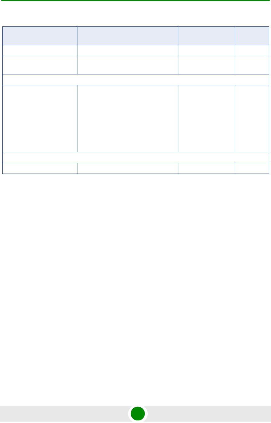
Chapter 4 - Operation and Administration Parameters Summary
BreezeMAX Extreme 242 System Manual
Daylight Saving End Date dd.mm Yes
Daylight Saving Advance
Factor
0 to 4:45 hours in 15 minutes steps +00:00 Yes
GPS - Clock Parameters
Clock Mode Master
Slave#1
Slave#2
Slave#3
Slave#4
Master No
MS - Add (applicable only in Embedded Distributed ASN-GW Local Authentication working mode)
Select MS MAC MAC address Yes
Table 4-28: BTS Parameters Summary
Parameter Range Default Run-Time
Updated

Glossary

Glossary
BreezeMAX Extreme 255 System Manual
AAA Authentication, Authorization, and Accounting (pronounced "triple a."). A system (or
several systems) that controls what resources users have access to, and keeps
track of the activity of users over the network.
AAS Adaptive Antenna System, also called Advanced Antenna System, is a technology to
enable the network operators to increase the wireless network capacity. In addition,
adaptive antenna systems offer the potential of increased spectrum efficiency,
extended range of coverage and higher rate of frequency reuse. Adaptive antenna
systems consist of multiple antenna elements at the transmitting and/or receiving
side of the communication link, whose signals are processed adaptively in order to
exploit the spatial dimension of the mobile radio channel. Depending on whether the
processing is performed at the transmitter, receiver, or both ends of the
communication link, the adaptive antenna technique is defined as multiple-input
single-output (MISO), single-input multiple-output (SIMO), or multiple-input
multiple-output (MIMO).
ASCII American Standard Code for Information Interchange. A code for representing
English characters as numbers, with each letter assigned a number from 0 to 127.
ASN Access Service Network. An ASN is defined as a complete set of network functions
needed to provide radio access to a WiMAX subscriber. An ASN is comprised of
network elements such as one or more Base Stations (BS) and one or more ASN
gateways (ASN-GW). An ASN may be shared by more than one Connectivity
Service Network (CSN).
ASN-GW Access Service Network Gateway. The ASN-GW is a network entity that acts as a
gateway between the ASN and CSN. The ASN functions hosted in an ASN-GW may
be viewed as consisting of two groups - the decision point (DP) that provides control
functionality and enforcement point (EP) that provides bearer transport.
AU Access Unit
AWG An electronics industry acronym for American Wire Gauge. AWG is a measure of the
thickness of copper, aluminum and other wiring.
BTS Base Transceiver Station. A wireless network element that provides the radio
interface of the network. The BTS comprises the radio transmission and reception
devices, and also manages the signal processing related to the air interface.
BW Bandwidth
CINR Carrier-to-Interference plus Noise Ratio (expressed in dB)
CIR Committed Information Rate. The rate (in bits per second) at which a network
guarantees to transfer information under normal conditions, averaged over a
minimum increment of time.
CLI Command Line Interface. A user interface that accepts typed commands to instruct
the managed device on the task to perform.
CPU Central Processing Unit.
CS Convergence Sublayer. Particular protocols that are responsible for gathering and
formatting higher layer information so it can be processed by the lower layers.

Glossary
BreezeMAX Extreme 256 System Manual
CSMA/CD Carrier Sense Multiple Access with Collision Detection. Media-access mechanisms
wherein devices ready to transmit data first check the channel for a carrier. If no
carrier is sensed for a specific period of time, a device can transmit. If two devices
transmit at once, a collision occurs and is detected by all colliding devices. This
collision subsequently delays retransmissions from those devices for some random
length of time. Ethernet and IEEE 802.3 use CSMA/CD access.
CSN Connectivity Service Network. A CSN is defined as a set of network functions that
provide IP connectivity services to WiMAX subscribers and all the IP core network
functions. A CSN is comprised of network elements such as routers, proxy/servers,
user databases, and inter-working gateway devices.
CTC Convolutional Turbo Code is a type of turbo codes with some of the convolutional
schemes used. For its high-performance error correction nature, CTC is the iterative
decoding scheme of choice as evidenced by their wide adoption in standards bodies.
DCD Downlink Channel Descriptor.
DHCP Dynamic Host Configuration Protocol. A protocol for dynamically assigning IP
addresses from a pre-defined list to nodes on a network. Using DHCP to manage IP
addresses simplifies client configuration and efficiently utilizes IP addresses.
DL Down Link
DSCP Differentiated Service Code Point, AKA DiffServ: An alternate use for the ToS byte in
IP packets. Six bits of this byte are being reallocated for use as the DSCP field
where each DSCP specifies a particular per-hop behavior that is applied to the
packet.
DNS Domain Naming System. A system that stores information about hostnames and
domain names. DNS provides an IP address for each hostname, and lists the e-mail
exchange servers accepting e-mail addresses for each domain.
DSL Digital Subscriber Line. A technology that exploits unused frequencies on copper
telephone lines to transmit traffic typically at multi-megabit speeds. DSL can allow
voice and high-speed data to be sent simultaneously over the same line. Because
the service is 'always available,' end-users don't need to dial in or wait for call set-up.
EAP Extensible Authentication Protocol, A protocol used between a user station and an
authenticator or authentication server. It acts as a transport for authentication
methods or types. It, in turn may be encapsulated in other protocols, such as 802.1x
and RADIUS. EAP is defined by RFC 2284.
EDT Electrical Down-Tilt
EIRP Equivalent Isotropic Radiated Power. The apparent power transmitted towards the
receiver, if it is assumed that the signal is radiated equally in all directions. The EIRP
is equal to the power (in dBm) at the antenna port, plus the power gained from the
directivity of the antenna (in dBi).
EMC Electro-Magnetic Compatibility. The capability of equipment or systems to be used in
their intended environment within designed efficiency levels without causing or
receiving degradation due to unintentional EMI (Electro Magnetic Interference). EMC
generally encompasses all of the electromagnetic disciplines.

Glossary
BreezeMAX Extreme 257 System Manual
ETS European Telecommunications Standard
ETSI European Telecommunications Standards Institute. A non-profit organization
producing voluntary telecommunications standards used throughout Europe, some
of which have been adopted by the EC as the technical base for Directives or
Regulations.
GPS Global Positioning System. A system that uses satellites, receivers and software to
allow users to determine their precise geographic position.
GRE General Routing Encapsulation. A method or technique of adding an IP standard
header and trailer to a message that does not follow IP protocols. The encapsulated
message is sent over a public network while received messages are stripped of the
wrapper and processed. This permits non-standard data and totally encrypted
messages to use the Internet. The technology is an important element in Virtual
Private Network (VPN) offerings.
HP High Power.
IEEE Institute of Electrical and Electronics Engineers. IEEE (pronounced I-triple-E) is an
organization of engineers, scientists, and students. The IEEE is best known for
developing standards for the computer and electronics industry. In particular, the
IEEE 802 standards for local-area networks are widely followed.
IEEE 802.16 Also known as WIMAX. A group of broadband wireless communications standards
for metropolitan area networks (MANs) developed by a working group of the IEEE.
IEEE 802.16e 802.16e, also known as 802.16-2005, is an IEEE standard addressing mobility of
wireless broadband (WiMax). IEEE 802.16e is sometimes called Mobile WiMAX,
after the WiMAX forum for interoperability. 802.16e, based on an existing WiMAX
standard 802.16a, adds WiMAX mobility in the 2-to-6 GHz-licensed bands. 802.16e
allows for fixed wireless and mobile Non Line of Sight (NLOS) applications primarily
by enhancing the OFDMA (Orthogonal Frequency Division Multiple Access).
IEEE 802.1p A QoS method - A three-bit value that can be placed inside an 802.1Q frame tag.
IEEE 802.1q The IEEE 802.1q standard defines the operation of VLAN Bridges that permit the
definition, operation and administration of Virtual LAN topologies within a Bridged
LAN infrastructure. The 802.1q specification establishes a standard method for
inserting VLAN membership information into Ethernet frames. A tag field containing
VLAN (and/or 802.1p priority) information can be inserted into an Ethernet frame,
carrying VLAN membership information.
IEEE 802.3 A Local Area Network protocol suite commonly known as Ethernet. Ethernet uses
Carrier Sense Multiple Access bus with Collision Detection CSMA/CD. This method
allows users to share the network cable. However, only one station can use the
cable at a time. A variety of physical medium dependent protocols are supported.
IF Intermediate Frequency. Radio communications systems modulate a carrier
frequency with a baseband signal in order to achieve radio transmission. In many
cases, the carrier is not modulated directly. Instead, a lower IF signal is modulated
and processed. At a later circuit stage, the IF signal is converted up to the
transmission frequency band.

Glossary
BreezeMAX Extreme 258 System Manual
IGMP Internet Group Membership Protocol) is protocol used by IP hosts to report their host
group memberships to any immediately neighboring multicast routers.
The use of IP multicasting in TCP/IP networks is defined as a TCP/IP standard in
RFC 1112. In addition to defining address and host extensions for how IP hosts
support multicasting, this RFC also defines the IGMP version 1. Version 2 of IGMP is
defined in RFC 2236. Both versions of IGMP provide a protocol to exchange and
update information about host membership in specific multicast groups.
IP Internet Protocol. The standard that defines how data is transmitted over the
Internet. IP bundles data, including e-mail, faxes, voice calls and messages, and
other types, into "packets", in order to transmit it over public and private networks.
LED Light Emitting Diode.
MAC Media Access Control. The lower of the two sub-layers of the data link layer defined
by the IEEE. The MAC sub-layer handles access to shared media, such as whether
token passing or contention will be used.
MAC Address Standardized data link layer address that is required for every port or device that
connects to a LAN. Other devices in the network use these addresses to locate
specific ports in the network and to create and update routing tables and data
structures. MAC addresses are 6bytes long and are controlled by the IEEE.
MDT Mechanical Down-Tilt
MIB Management Information Base. A database of objects that can be monitored by a
network management system. SNMP uses standardized MIB formats that allow any
SNMP tools to monitor any device defined by a MIB.
MIMO Multiple Input, Multiple Output. A technique for faster wireless communication.
MIMO allows for the use of multiple transmitter and receiver antennas to increase
throughput and range.
MIP Mobile IP. A protocol used to provide IP mobility to IPv4-based nodes, defined in
RFC-2002.
MIR Maximum Information Rate. Specifies the maximum rate of information that can be
available to a user. The MIR is used by the traffic policing mechanism to prevent
users from sending excess traffic to the network.
MTU Maximum Transmission Unit. This is the greatest amount of data that can be
transferred in one physical frame on the network. If a packet that has a smaller MTU
than the packet's frame length is sent, fragmentation will occur. For TCP, MTU can
range from 68 to 1500 bytes. Larger MTUs provide for lower overhead (fewer
headers).
MS Mobile Station. The equipment used by the end user to access the WiMAX network.
NAP Network Access Provider. A NAP is a business entity that provides WiMAX radio
access infrastructure to one or more Network Service Providers (NSPs). An NAP
implements this infrastructure using one or more ASNs.

Glossary
BreezeMAX Extreme 259 System Manual
NMS Network Management System. A system responsible for managing at least part of a
network. An NMS is generally a reasonably powerful and well-equipped computer,
such as an engineering workstation. NMSs communicate with agents to help keep
track of network statistics and resources.
NSP Network Service Provider. An NSP is a business entity that provides IP connectivity
and WiMAX services to WiMAX subscribers compliant with the established service
level agreement. The NSP concept is an extension of the Internet service provider
(ISP) concept, providing network services beyond Internet access. To provide these
services, an NSP establishes contractual agreements with one or more NAPs. An
NSP may also establish roaming agreements with other NSPs and contractual
agreements with third-party application providers (e.g. ASP, ISP) for the delivery of
WiMAX services to subscribers. From a WiMAX subscriber standpoint, an NSP may
be classified as a home or visited NSP.
OFDM Orthogonal Frequency Division Multiplexing: A method for multiplexing signals,
which divides the available bandwidth into a series of frequencies known as tones.
Orthogonal tones do not interfere with each other when the peak of one tone
corresponds with the null. The rapid switching, frequency-hopping technique is
intended to allow more robust data service.
OFDMA Orthogonal Frequency Division Multiple Access. It’s a logical extension of OFDM
and a modulation/multiple access technique. OFDMA divides a signal into
sub-channels (i.e. groups of carriers), with each sub-channel (or several
sub-channels) being allocated to a different subscriber.
PER Packet Error Rate. In a digital transmission, PER is the percentage of packets with
errors divided by the total number of packets that have been transmitted, received or
processed over a given time period.
PHY PHYsical Layer. The physical, or lowest, layer of the OSI Network Model. In a
wireless network, the PHY defines parameters such as data rates, modulation
method, signaling parameters, transmitter/receiver synchronization, etc. Within an
actual radio implementation, the PHY corresponds to the radio front end and
baseband signal processing sections.
PS Power Supply
QoS Quality of Service. Measure of performance for a transmission system that reflects
its transmission quality and service availability.
QPSK Quadrature Phase Shift Keying. A data transfer technique used in coaxial cable
networks that sends data using modulating signals. Four different phases represent
data, with each signal's information determined by the signal before it. For example,
if a phase stays the same from one signal to the other, the information has not
changed.
RADIUS Remote Authentication Dial-In User Service, an authentication and accounting
system used by many Internet Service Providers (ISPs). When you connect to the
system you must enter your username and password. This information is passed to
a RADIUS server, which checks that the information is correct, and then authorizes
access to the system.

Glossary
BreezeMAX Extreme 260 System Manual
RF Radio frequency. An AC signal of high enough frequency to be used for wireless
communications.
RFC Request For Comments. The name of the result and the process for creating a
standard on the Internet. New standards are proposed and published on the Internet,
as a Request For Comments. The proposal is reviewed by the Internet Engineering
Task Force.
RoHS Restriction of the use of certain Hazardous Substances in electrical and electronic
equipment, reference EC Directive 2002/95/EC of 27 January 2003.
RSSI Received Signal Strength Indicator. A signal or circuit that indicates the strength of
the incoming (received) signal in a receiver.
Rx Receive
SNMP Simple Network Management Protocol. A network management protocol that
provides a means to monitor and control network devices, and to manage
configurations, statistics collection, performance, and security. SNMP works by
sending messages, called protocol data units (PDUs), to different parts of a network.
SNMP-compliant devices, called agents, store data about themselves in
Management Information Bases (MIBs) and return this data to the SNMP
requesters.
SSH Secure Shell is a protocol for secure remote login and other secure network services
over an insecure network.
TCP Transmission Control Protocol. Connection-oriented transport layer protocol that
provides reliable full-duplex data transmission. TCP is the part of the TCP/IP suite of
protocols that is responsible for forming data connections between nodes that are
reliable, as opposed to IP, which is connectionless and unreliable.
TFTP Trivial File Transfer Protocol. Simplified version of FTP that allows files to be
transferred from one computer to another over a network, usually without the use of
client authentication.
Tx Transmit
UAbbreviation for "Unit" or standard height measurement which defines the vertical
height for plug-in modules in the 19” construction system. One U equals 44.5 mm.
UCD Uplink Channel Descriptor.
UDP User Datagram Protocol. Connectionless transport layer protocol in the TCP/IP
protocol stack. UDP is a simple protocol that exchanges datagrams without
acknowledgments or guaranteed delivery, requiring that error processing and
retransmission be handled by other protocols. UDP is defined in RFC 768.
UL Up Link
VLAN Virtual Local Area Network. A group of devices on one or more LANs that are
configured with the same VLAN ID so that they can communicate as if they were
attached to the same wire, when in fact they are located on a number of different
LAN segments. Used also to create separation between different user groups.

Glossary
BreezeMAX Extreme 261 System Manual
VoIP Voice over Internet Protocol. Provides an advanced digital communications network
that bypasses the traditional public switched telephone system and uses the Internet
to transmit voice communication. VoIP enables people to use the Internet as the
transmission medium for telephone calls by sending voice data in packets using IP
rather than by traditional circuit switched transmissions of the PSTN.
WCS Wireless Communications Service is defined by the Federal Communications
Commission as radio communications that may provide fixed, mobile, radio location,
or satellite communication services to individuals and businesses within their
assigned spectrum block and geographical area. The WCS is in the 2.3 GHz band
from 2,305 to 2,320 MHz and 2,345 to 2,360 MHz.
WEEE Waste Electronic and Electrical Equipment. The purpose of Directive 2002/96/EC on
waste electrical and electronic equipment (WEEE) is, as a first priority, the
prevention of waste electrical and electronic equipment (WEEE), and in addition, the
reuse, recycling and other forms of recovery of such wastes so as to reduce the
disposal of waste. It also seeks to improve the environmental performance of all
operators involved in the life cycle of electrical and electronic equipment, e.g.
producers, distributors and consumers and in particular those operators directly
involved in the treatment of waste electrical and electronic equipment.
Wi-Fi Wi-Fi (short for wireless fidelity and pronounced 'why-fye') is a term for certain types
of wireless local area network that use specifications in the IEEE 802.11 family. The
term Wi-Fi was created by an organization called the Wi-Fi Alliance, which oversees
tests that certify product interoperability.
WiMAX WiMAX is an acronym that stands for Worldwide Interoperability for Microwave
Access. WiMAX is a standards-based technology enabling the delivery of last mile
wireless broadband access as an alternative to cable and DSL. WiMAX provides
fixed, nomadic, portable, and mobile wireless broadband connectivity without the
need for direct line-of-sight to a base station.
XML Extensible Markup Language. Language used for defining a set of markers, called
tags, that define the function and hierarchical relationships of the parts of a
document or data set. It is a flexible way to create common information formats and
share both the format and the data, most commonly on the web. It generally similar
to HTML and helps share information in a consistent way. XML is "extensible"
because, unlike HTML, the markup symbols are unlimited and self-defining.