Alvarion Technologies EXTR-50 BreezeMAX Extreme 5.8 Base Station User Manual BMAX Extreme System Manual
Alvarion Technologies Ltd. BreezeMAX Extreme 5.8 Base Station BMAX Extreme System Manual
UserManual.wiki
>
Alvarion Technologies
>
EXTR-50 User Manual
>
User manual 1
Contents
1.
user installation manual
2.
Updated user manual Correspondance 39238
3.
Professional Installer qualifications and Quick Installation guide
4.
User manual 1
5.
User manual 2
User manual 1
Navigation menu
Upload a User Manual
Namespaces
Wiki Guide
HTML
PDF
Info
Views
User Manual
Discussion / Help
Navigation
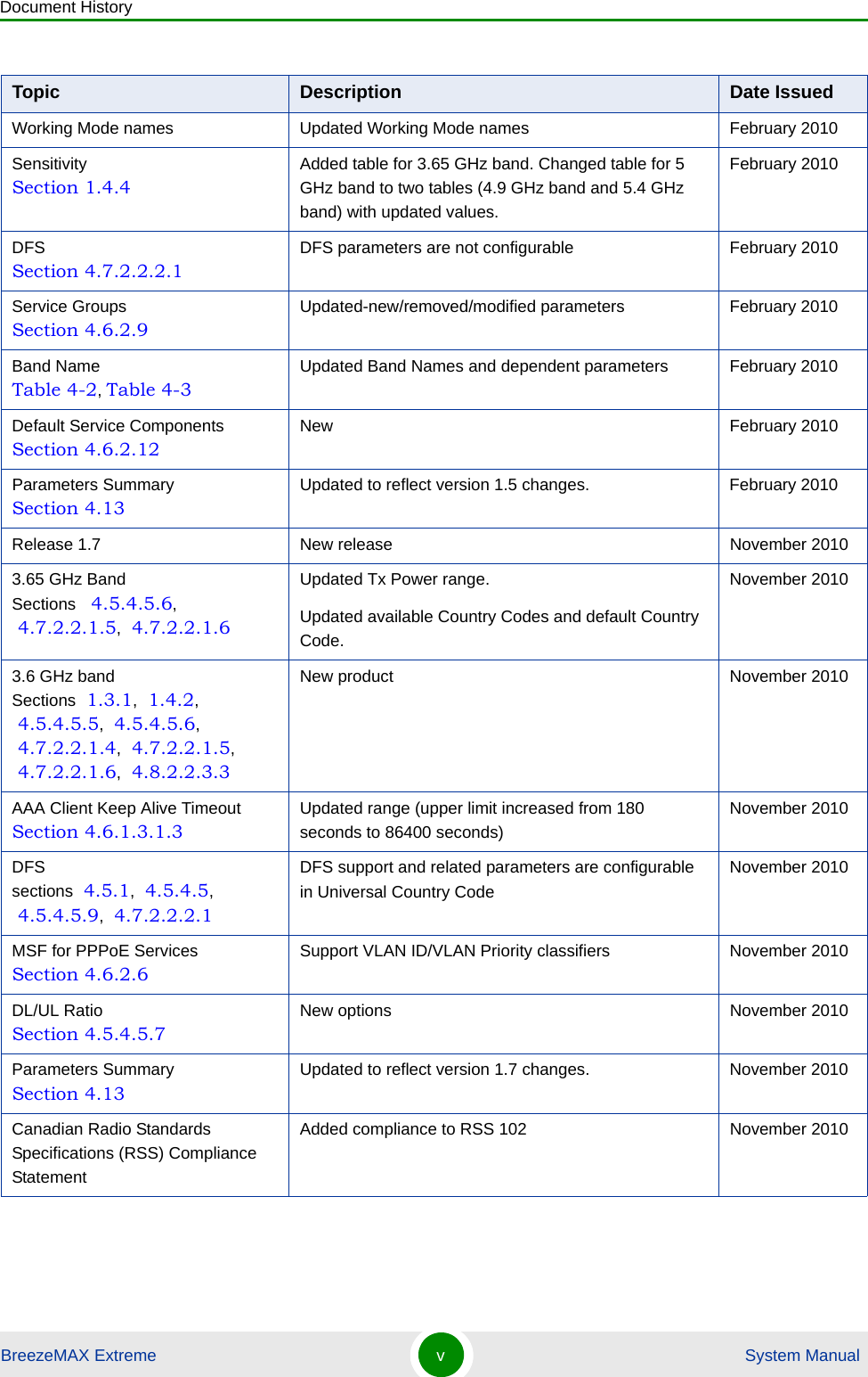
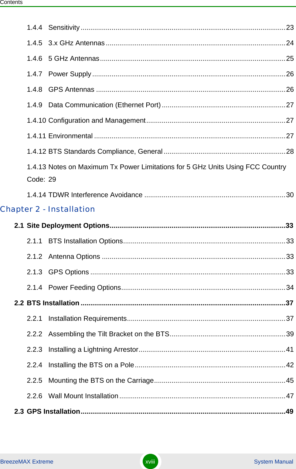
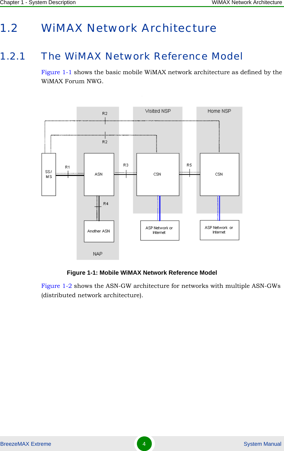
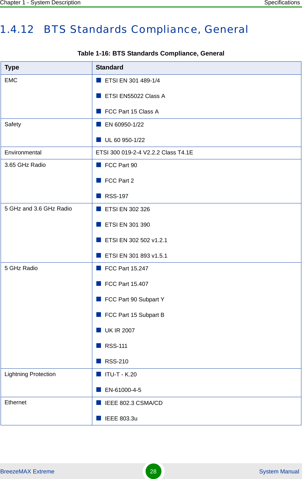
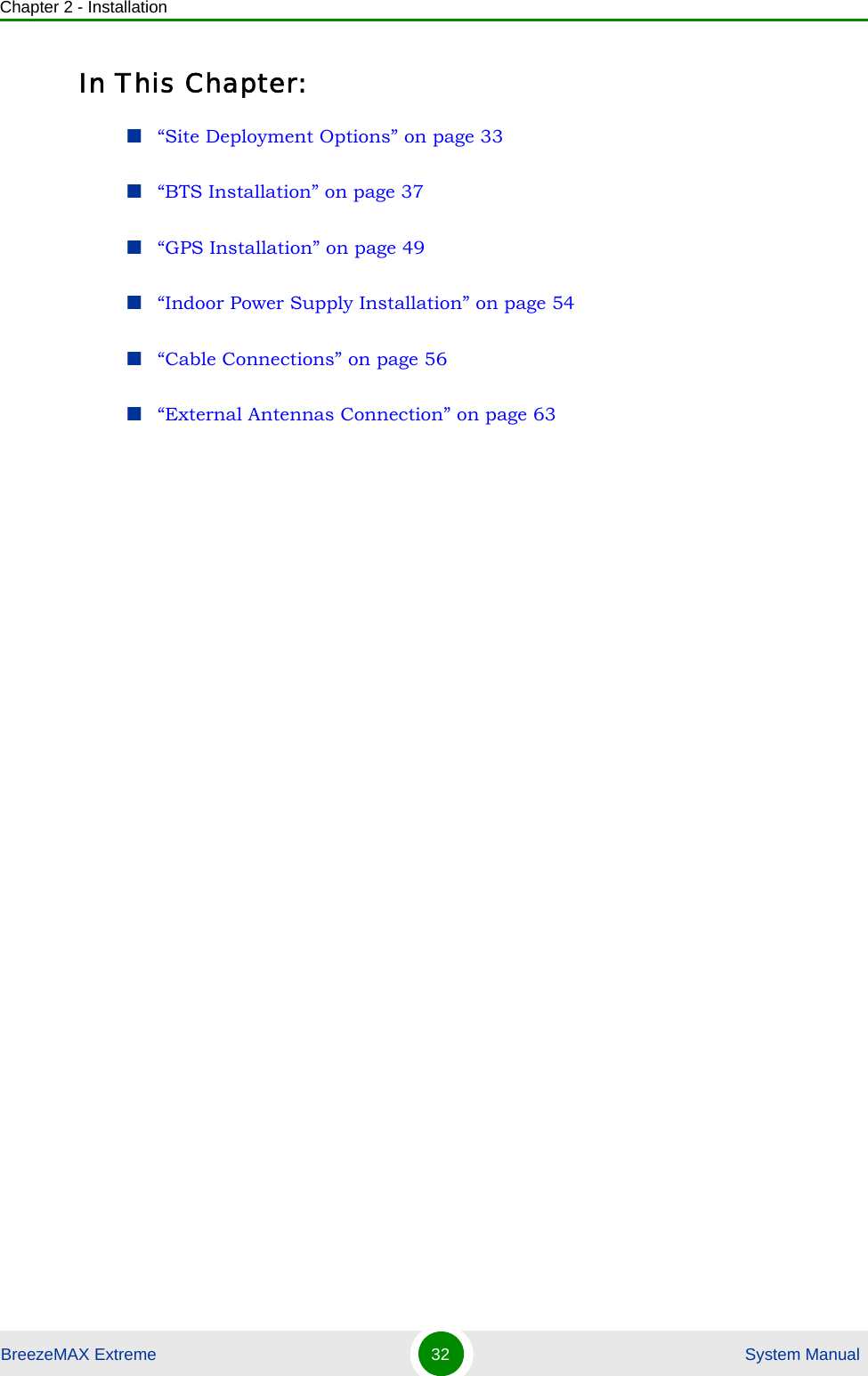
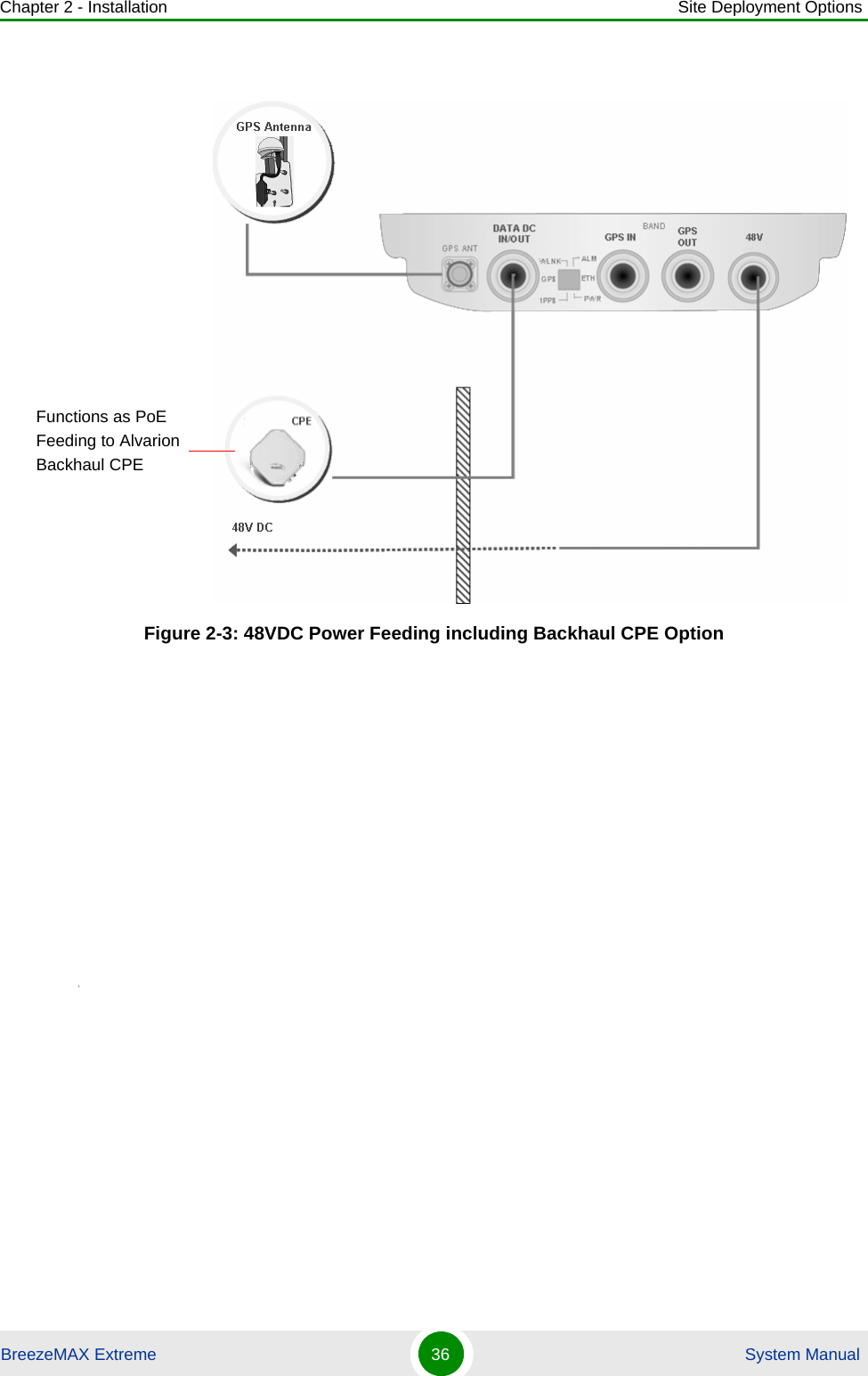
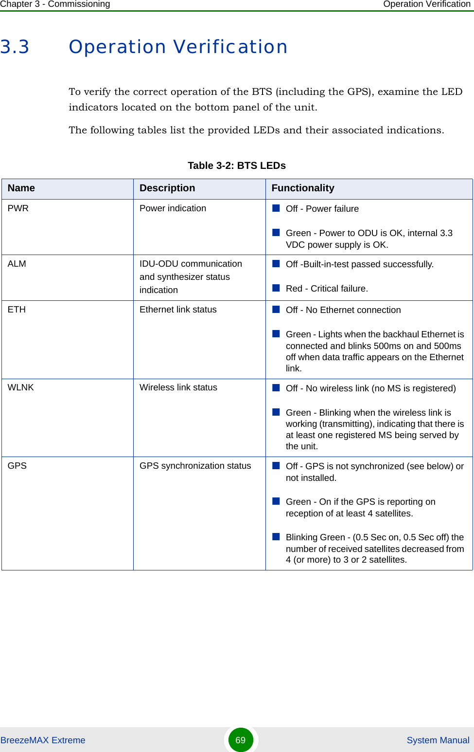
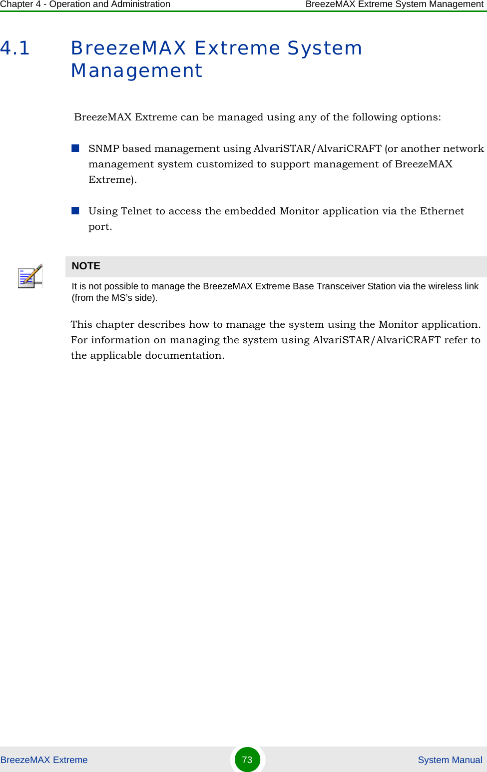
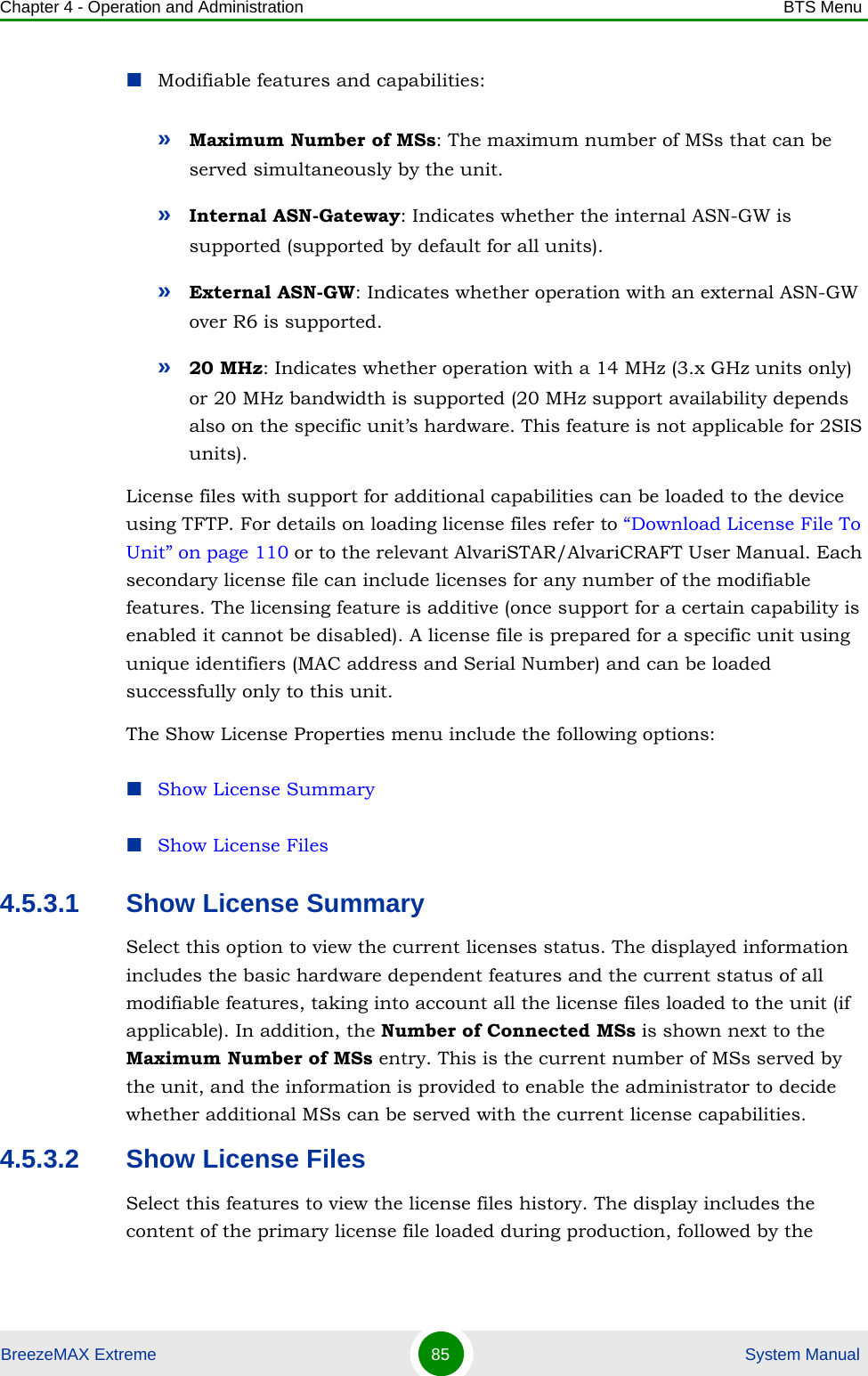
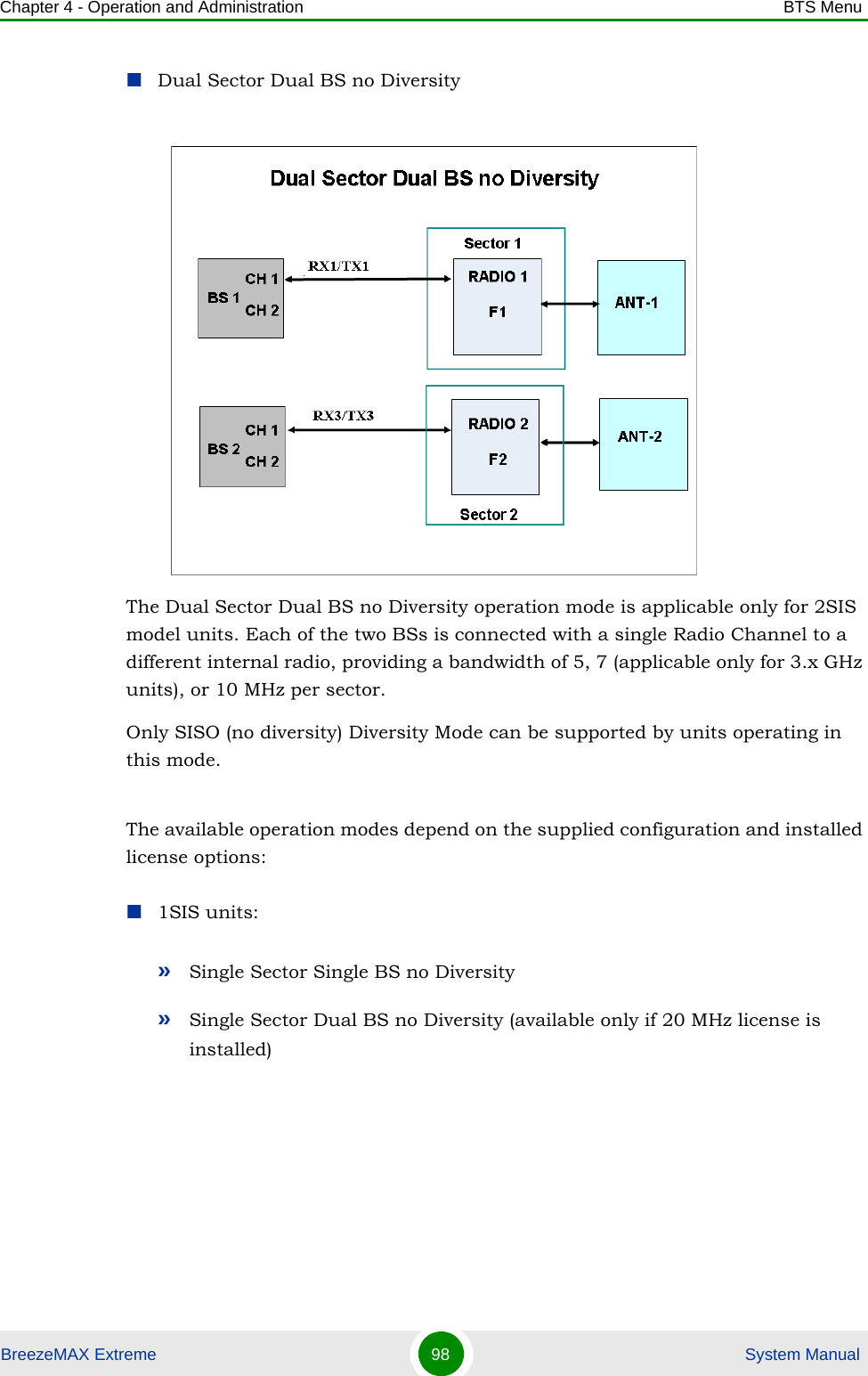
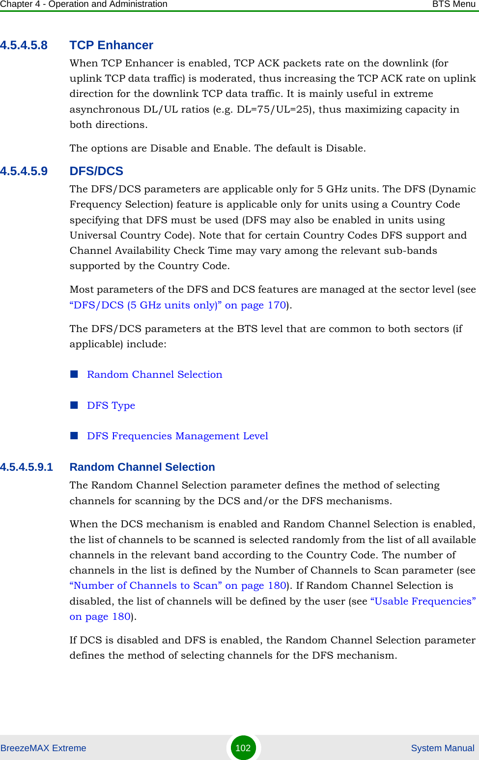
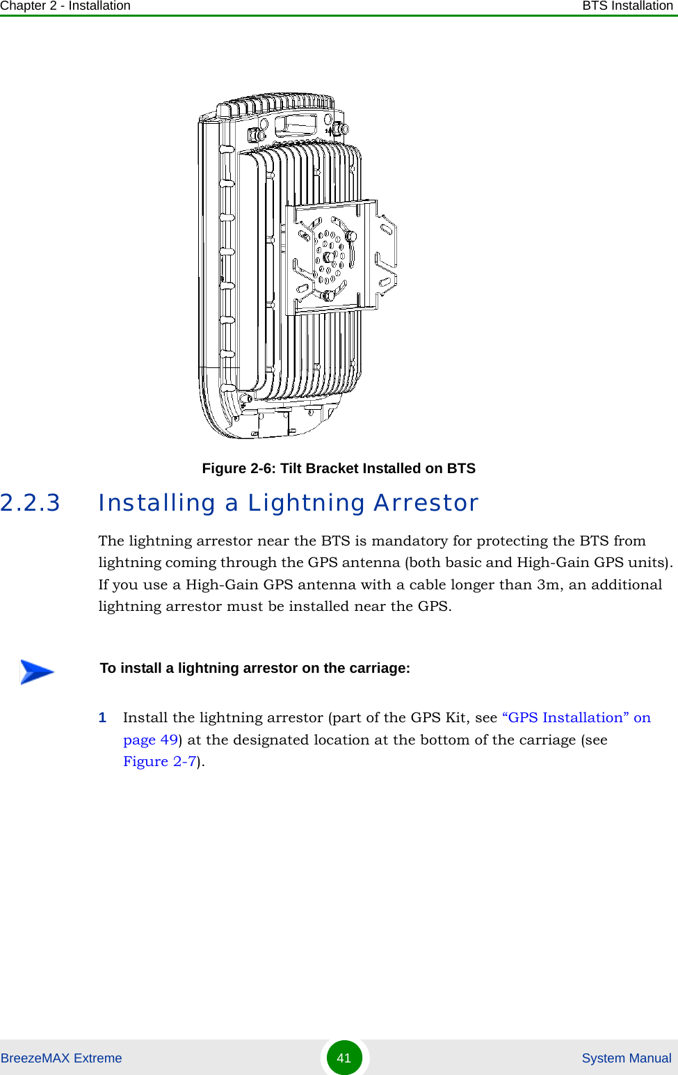
![Chapter 2 - Installation BTS InstallationBreezeMAX Extreme 40 System ManualPlace the tilt bracket on the BTS and fasten its M8 screws (see Figure 2-5 and Figure 2-6). Apply torque of 80 [Lib*In] = 9 [N*m]To assemble the bracket on the BTS:Figure 2-5: Assembling the Tilt Bracket on the BTSTilt bracketBTSM8X20 screwsCarrying grooves](https://usermanual.wiki/Alvarion-Technologies/EXTR-50.User-manual-1/User-Guide-1472911-Page-61.png)
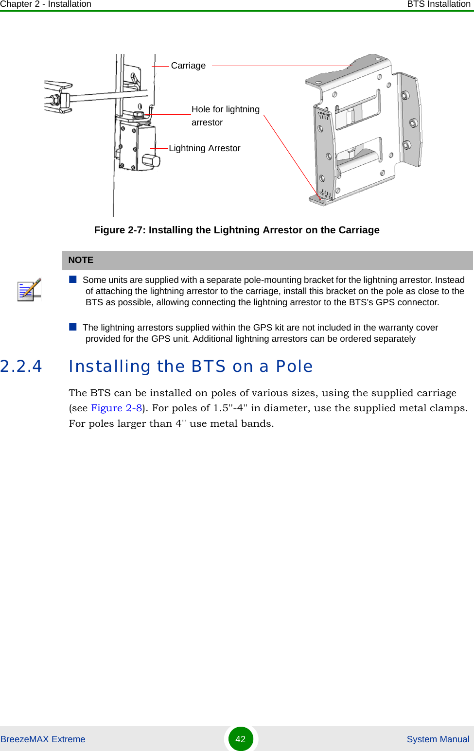
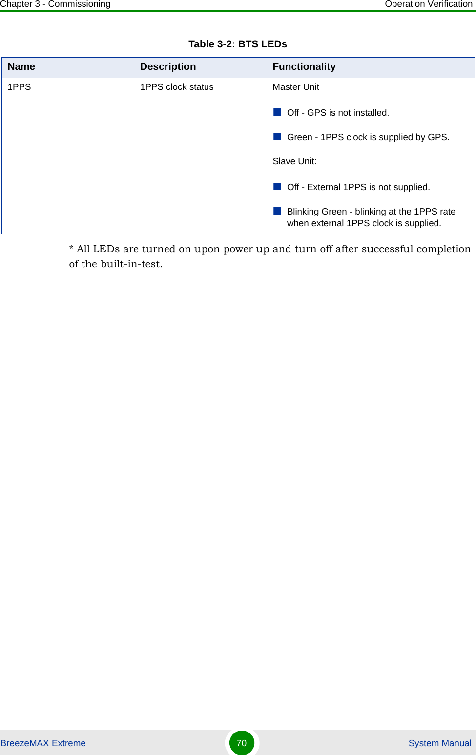
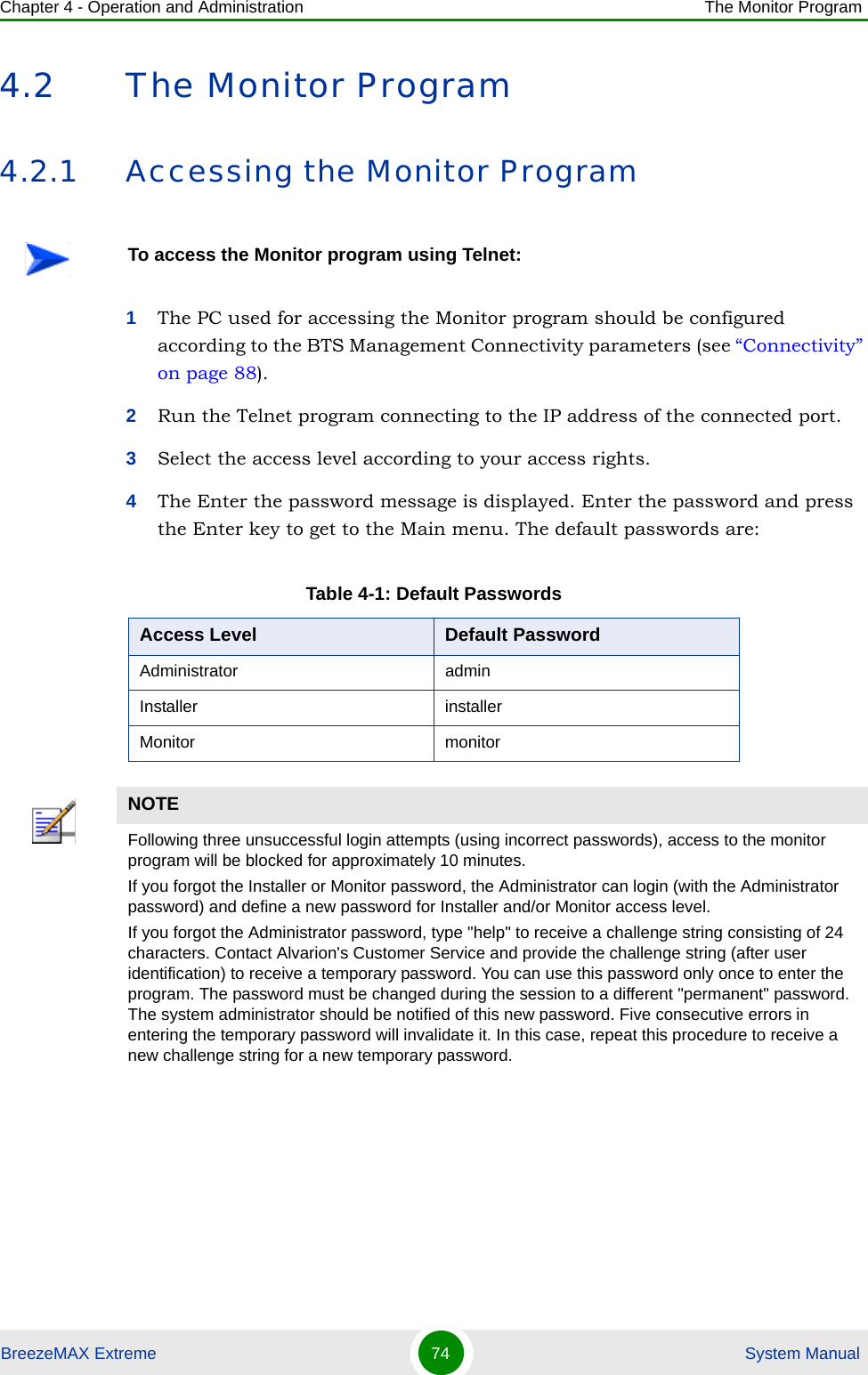
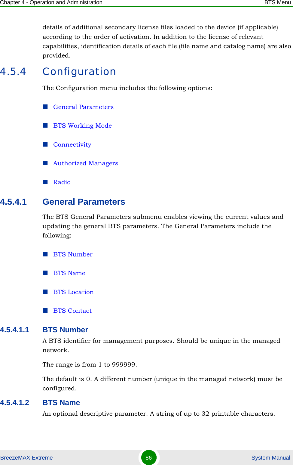
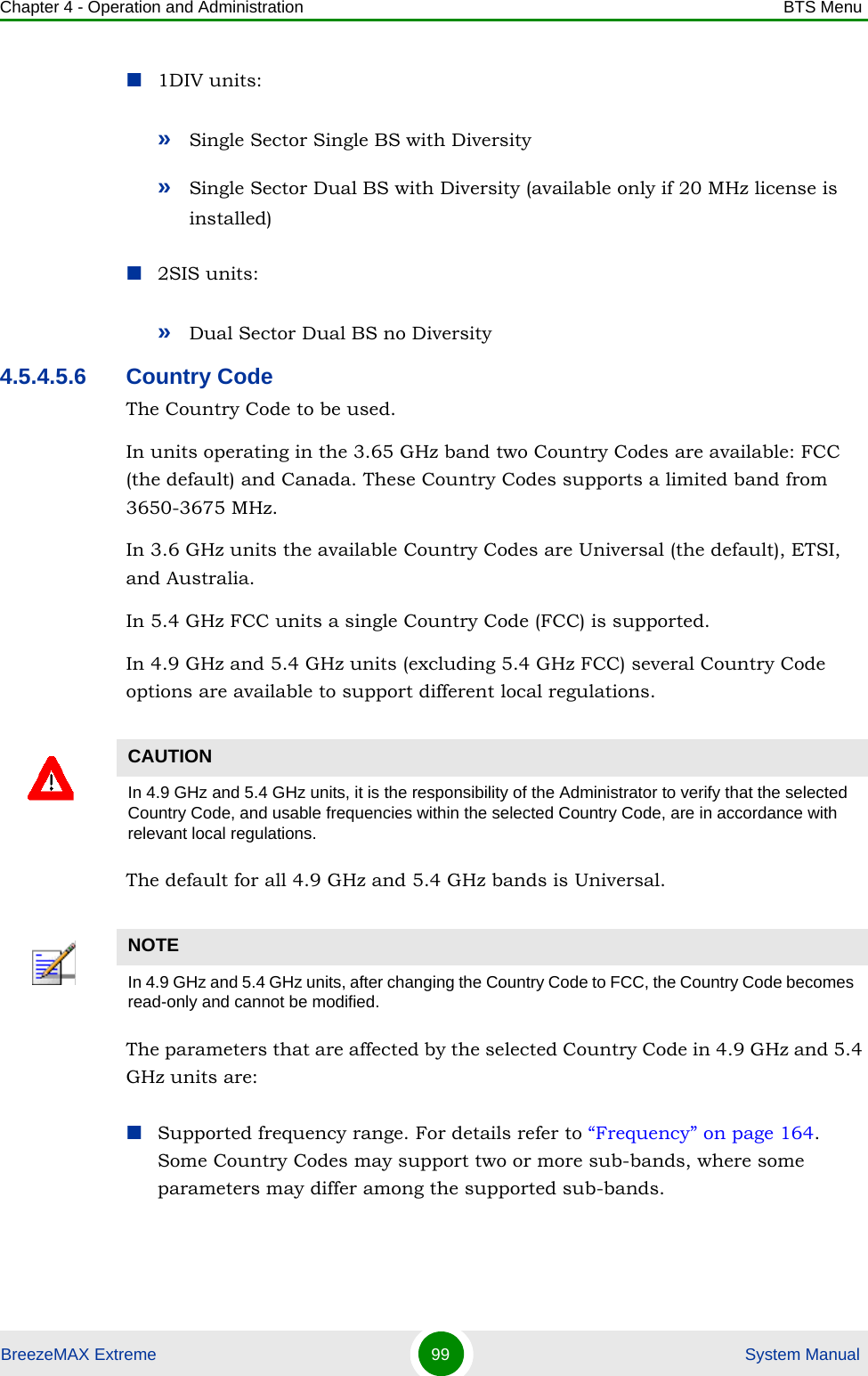
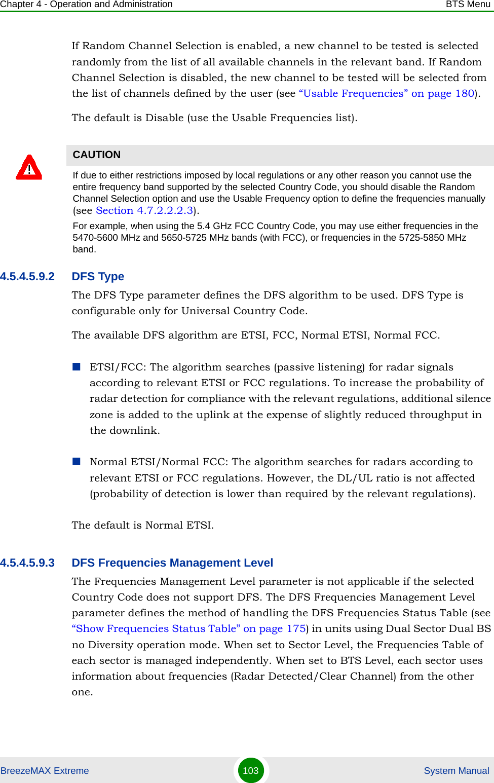
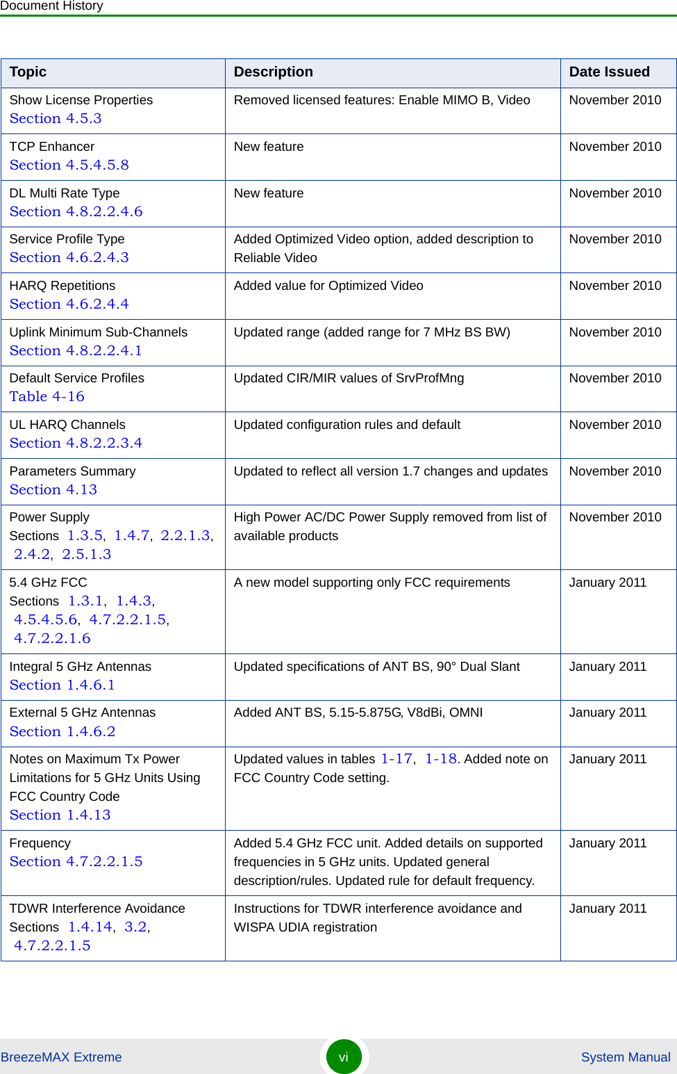
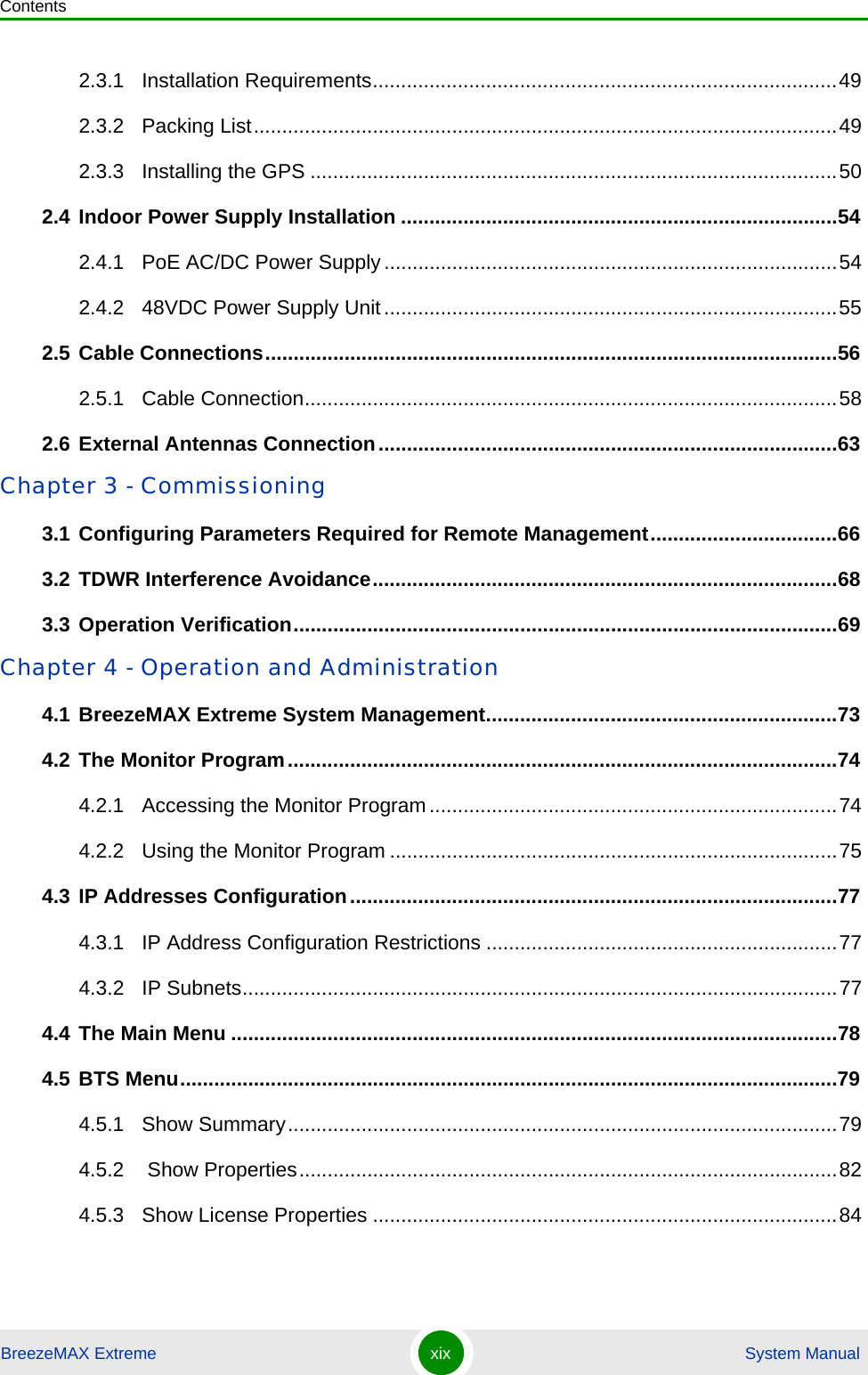
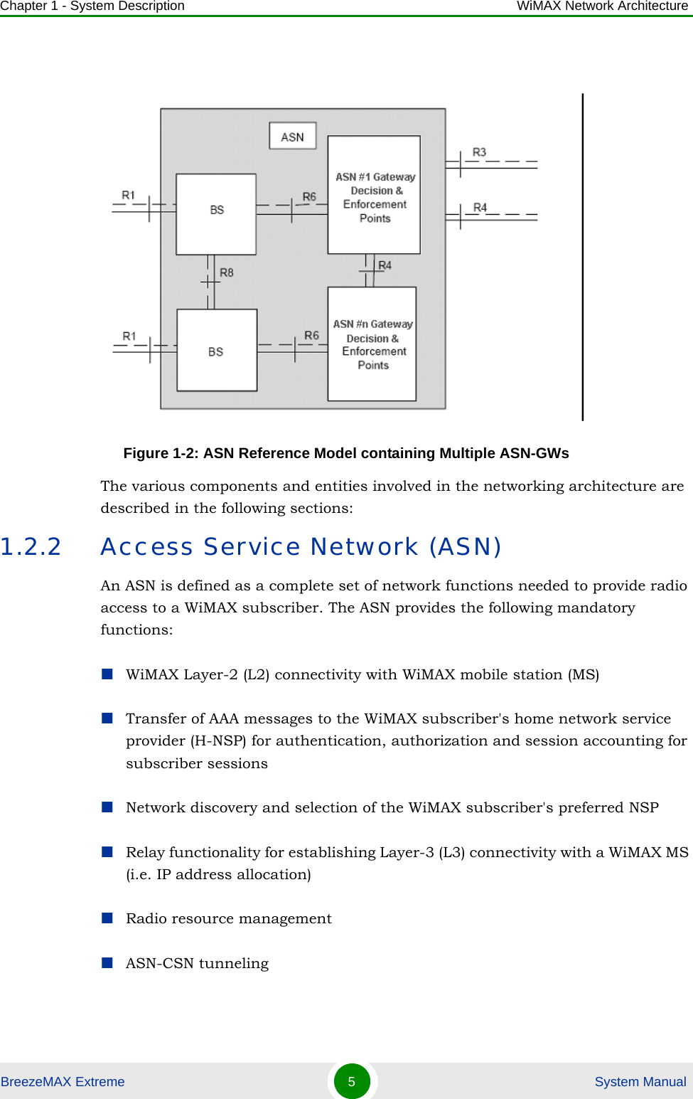
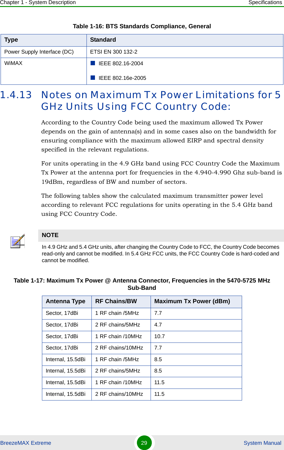
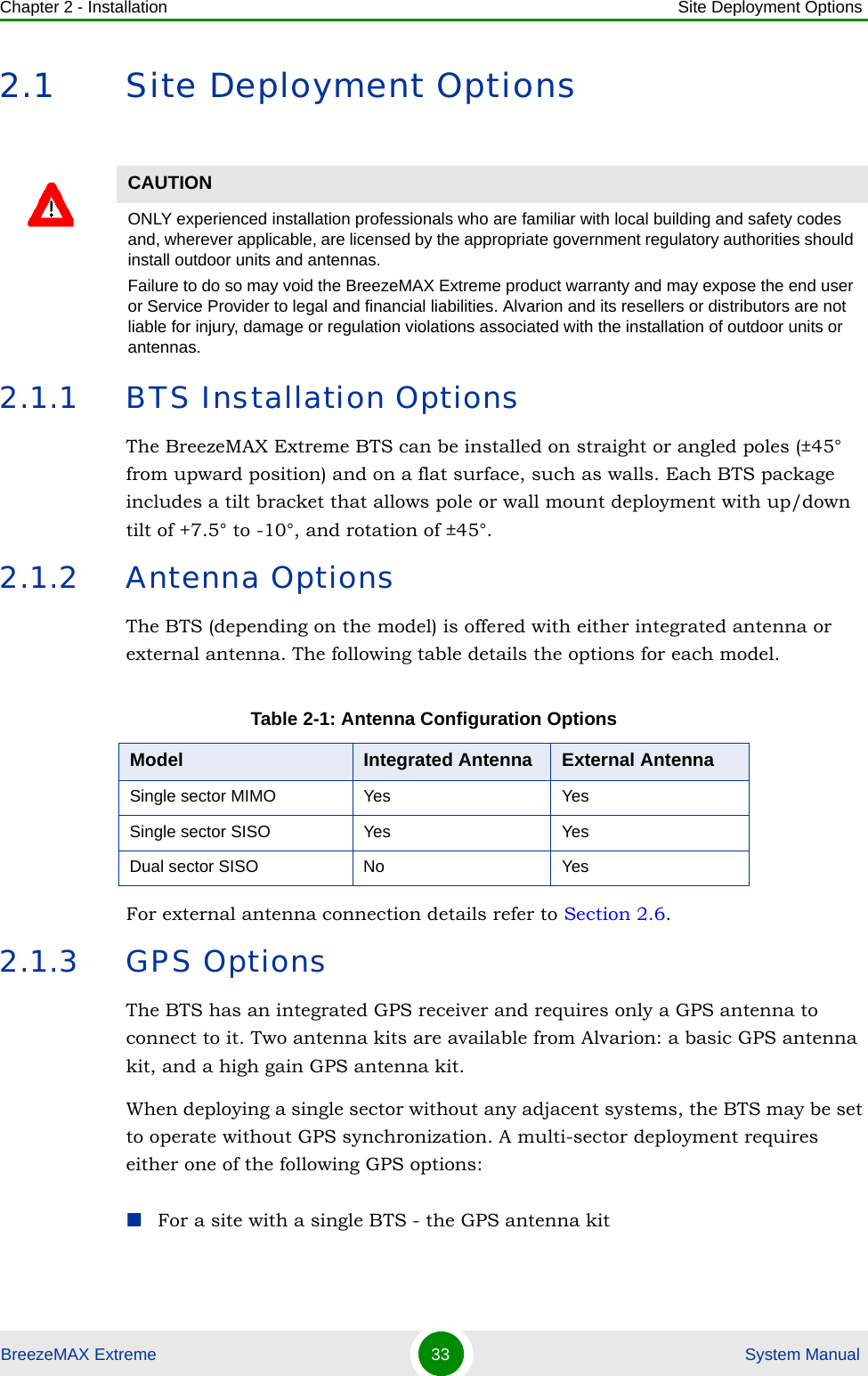
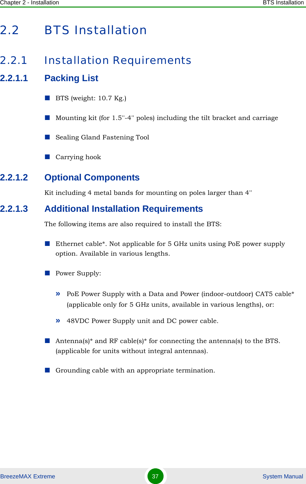
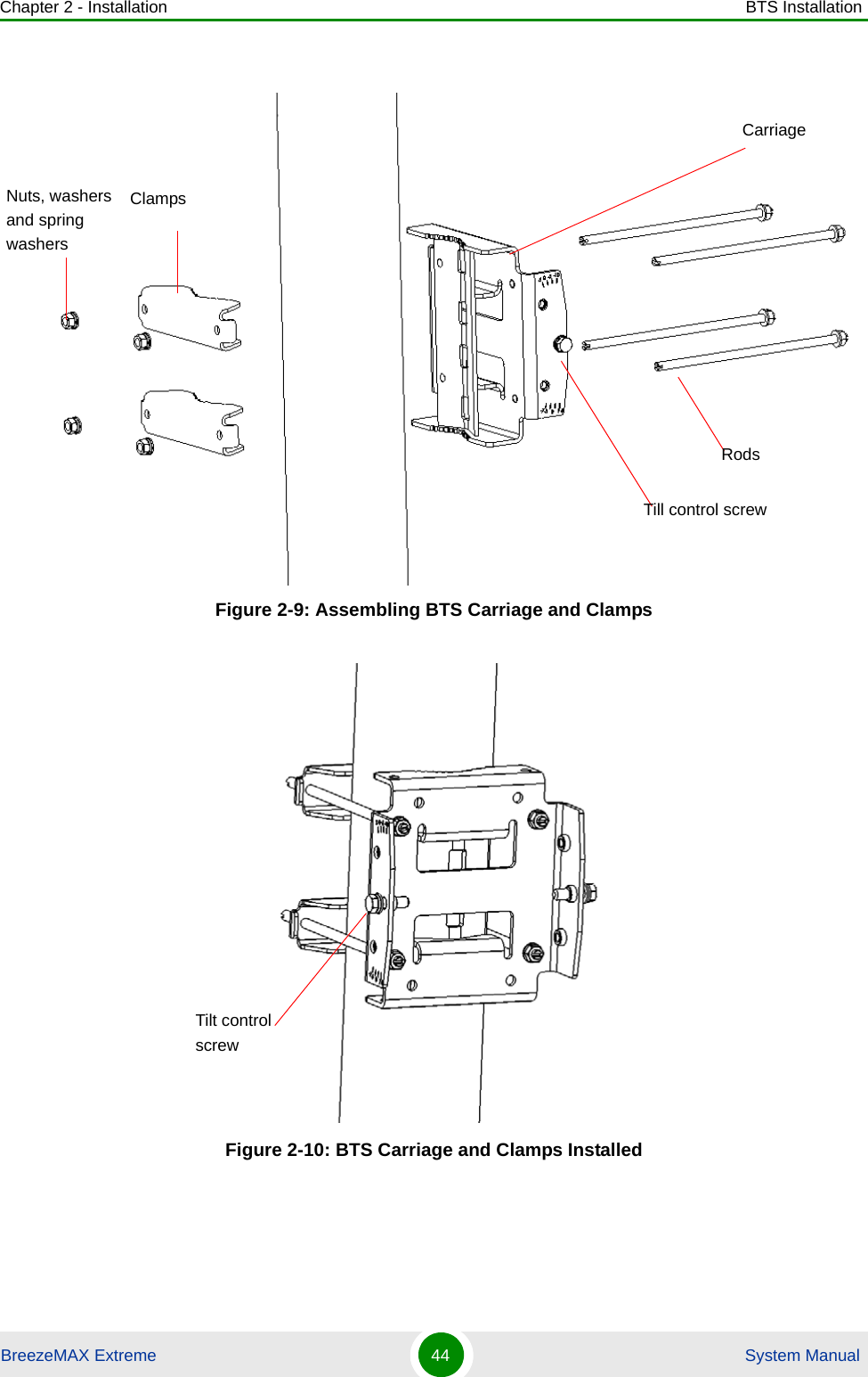
![Chapter 2 - Installation BTS InstallationBreezeMAX Extreme 43 System Manual1Assemble the tilt bracket on the BTS and fasten its four screws (see “Assembling the Tilt Bracket on the BTS” on page 39).2Install a lightning arrestor on the carriage as described in “Installing a Lightning Arrestor” on page 41.3Thread the four rods through the carriage.4Attach the carriage and the clamps to the pole and tighten on both sides using the supplied washers, spring washers and nuts. Apply torque of 80 [Lib*In] = 9 [N*m].5Insert the tilt control screws into the middle-side hole of the carriage on both sides.Figure 2-8: BreezeMAX Extreme Pole Mount CarriageTo install the Carriage on a 1.5''-4'' pole:Holes for pole mounting rods (x4)Holes for wall mounting screws (x4)Groove for metal bandsHoles for fastening screws (x4)Tilt control screws (x2)Holes for lightning arrestor (x4)](https://usermanual.wiki/Alvarion-Technologies/EXTR-50.User-manual-1/User-Guide-1472911-Page-64.png)
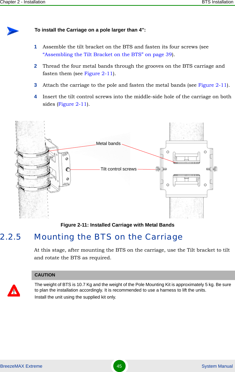
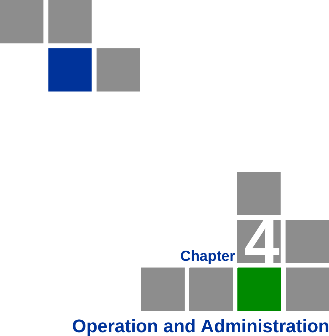
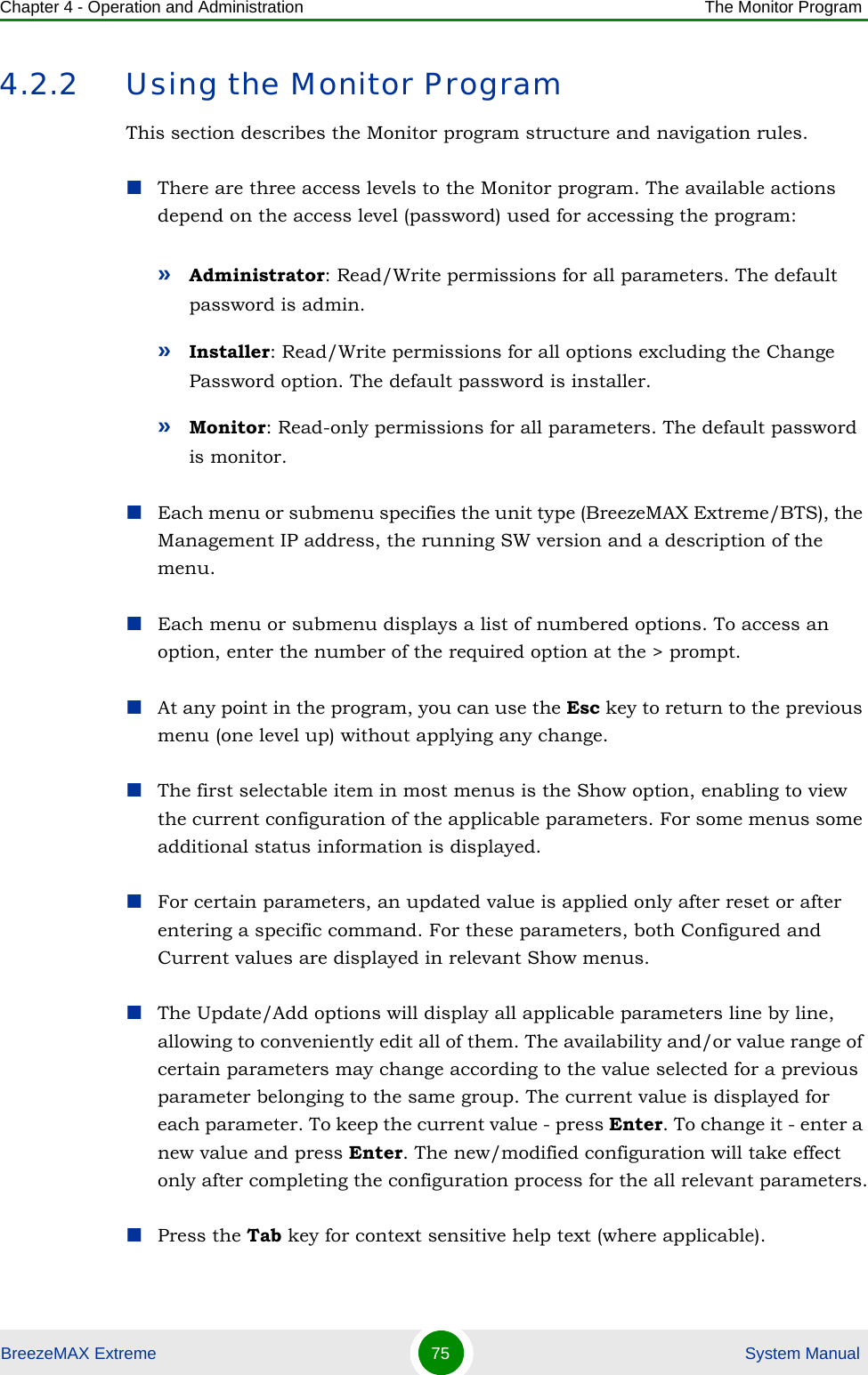
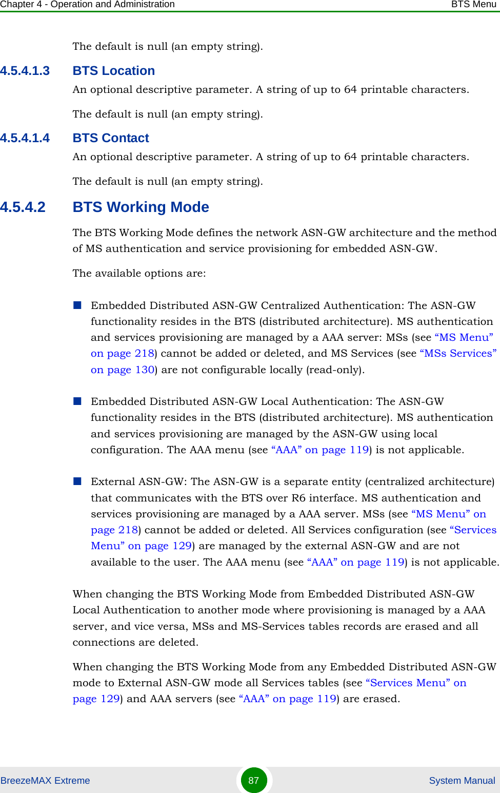
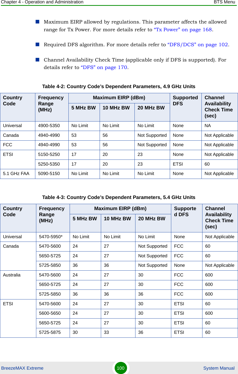
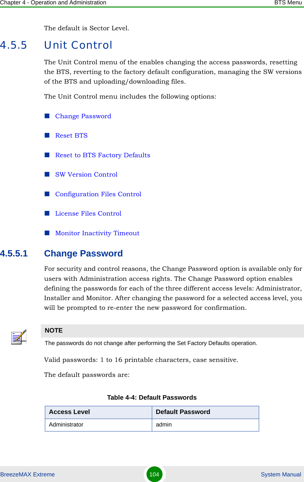
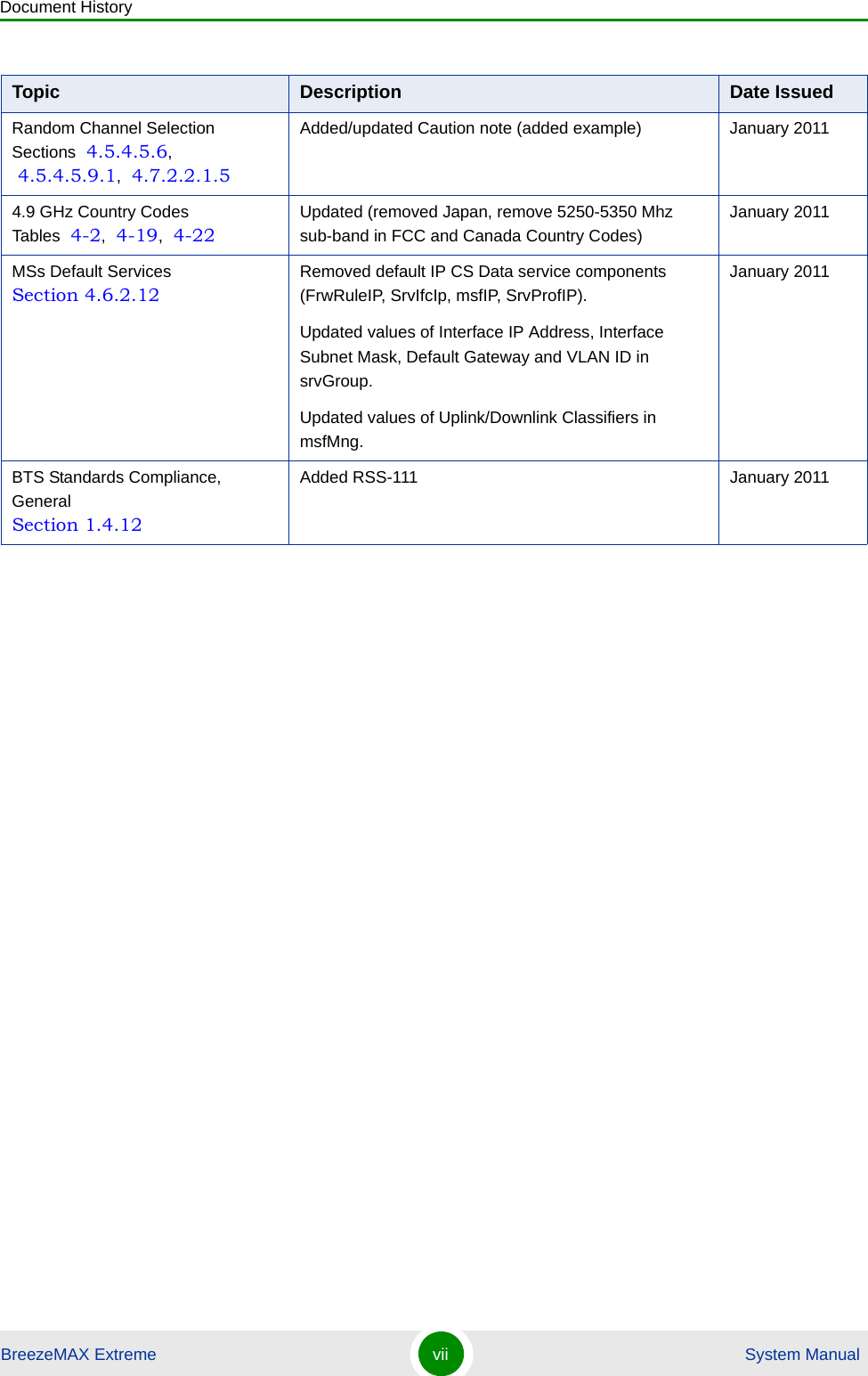
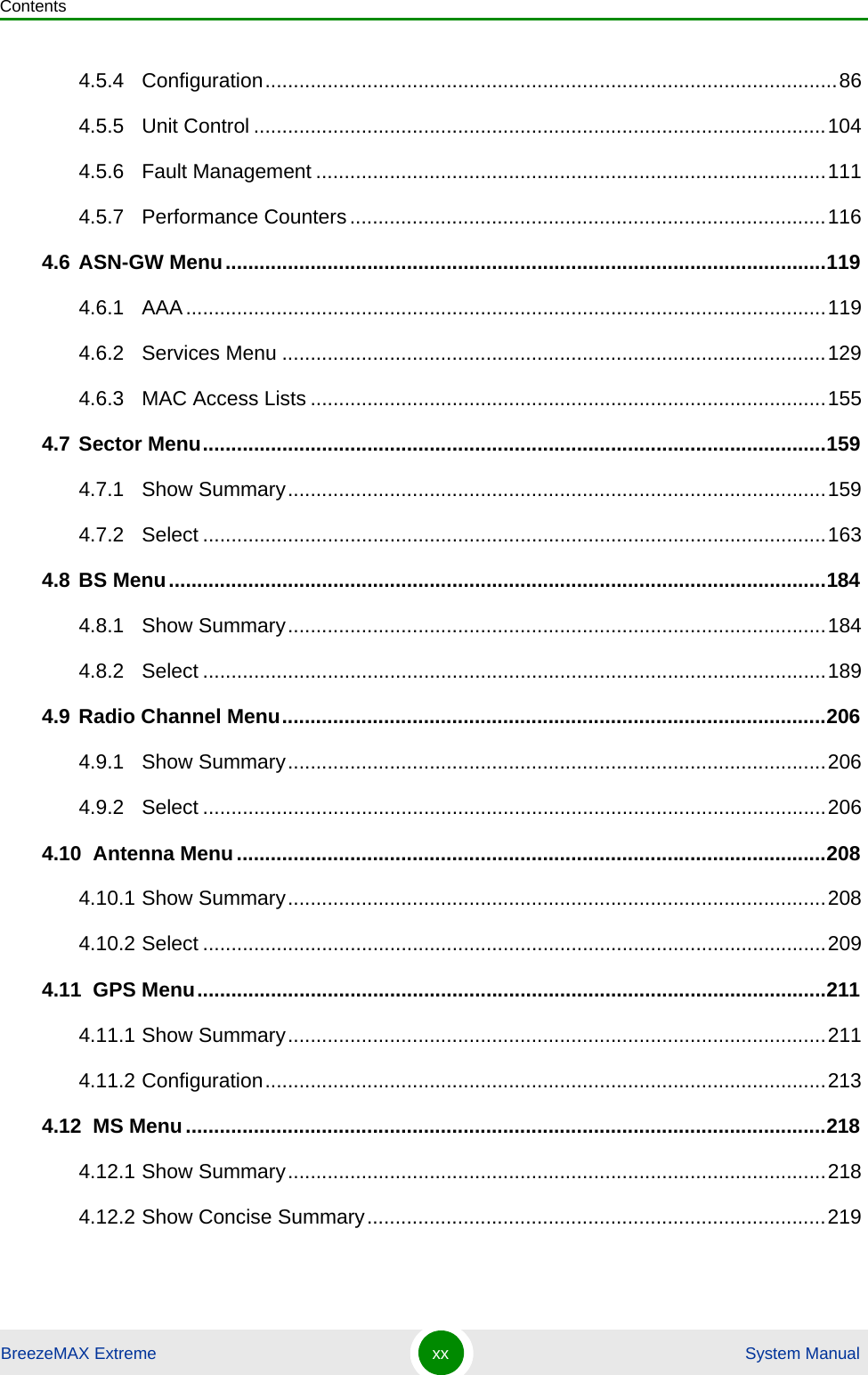
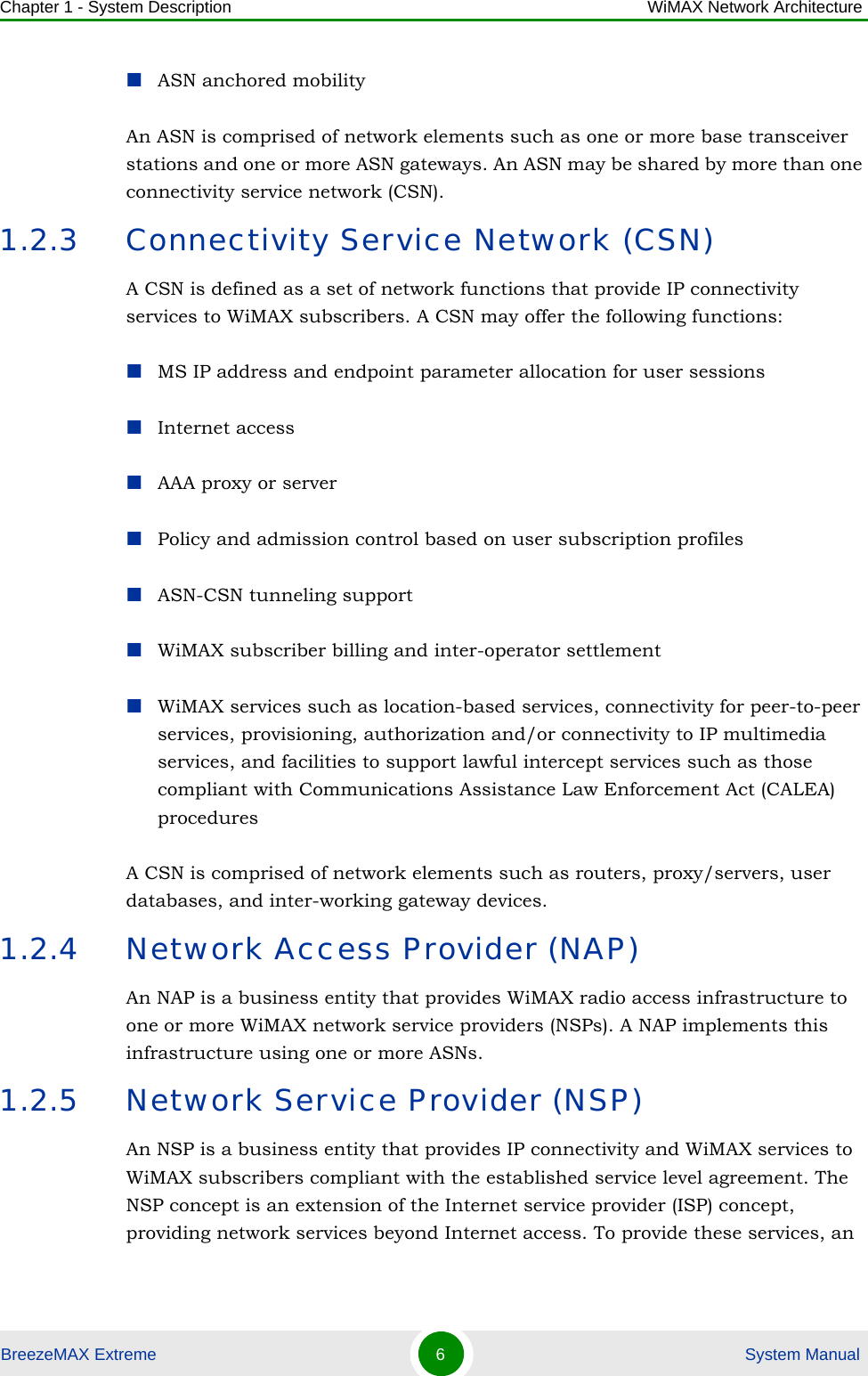
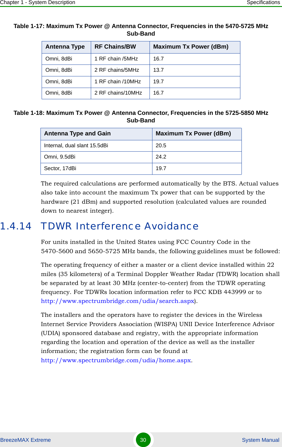
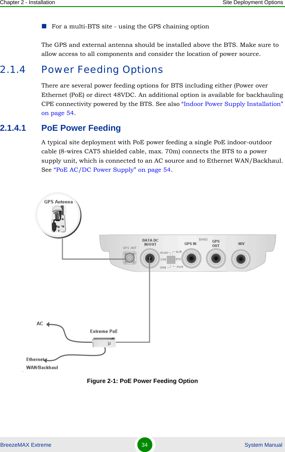
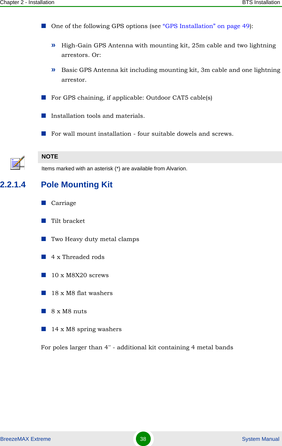
![Chapter 2 - Installation BTS InstallationBreezeMAX Extreme 47 System Manual3If required, slightly release the tilt bracket screws to enable rotation, and the tilt control screws to enable tilting; Adjust the BTS position and tighten the screws. Apply torques of 45 [Lib*In.] = 5 [N*m] to the M6 Tilt-control screws, and 80 [Lib*In] = 9 [N*m] to the M8 screws.2.2.6 Wall Mount InstallationThe BreezeMAX Extreme BTS can be installed on walls or any flat surface. This requires attaching and fastening the carriage with the BTS to the wall using suitable securing means (not supplied) and then tilting and rotating the BTS as required. The location of the screws should be planned with maximum precision.1Assemble the tilt bracket on the BTS and fasten its four screws (see “Assembling the Tilt Bracket on the BTS” on page 39).2If you use a High-Gain GPS antenna with a cable longer than 3m, install a lightning arrestor on the carriage as described in “Installing a Lightning Arrestor” on page 41.3Place the carriage on the wall and mark the exact location of the holes to drill. Figure 2-13: BTS Mounted on a Pole Larger than 4'' (with Metal Bands)To install the BTS on a wall:](https://usermanual.wiki/Alvarion-Technologies/EXTR-50.User-manual-1/User-Guide-1472911-Page-68.png)