Alvarion Technologies EXTR-50 BreezeMAX Extreme 5.4 Base Station User Manual BMAX Extreme
Alvarion Technologies Ltd. BreezeMAX Extreme 5.4 Base Station BMAX Extreme
UserManual.wiki
>
Alvarion Technologies
>
EXTR-50 User Manual
>
user installation manual
Contents
1.
user installation manual
2.
Updated user manual Correspondance 39238
3.
Professional Installer qualifications and Quick Installation guide
4.
User manual 1
5.
User manual 2
user installation manual
Navigation menu
Upload a User Manual
Namespaces
Wiki Guide
HTML
PDF
Info
Views
User Manual
Discussion / Help
Navigation
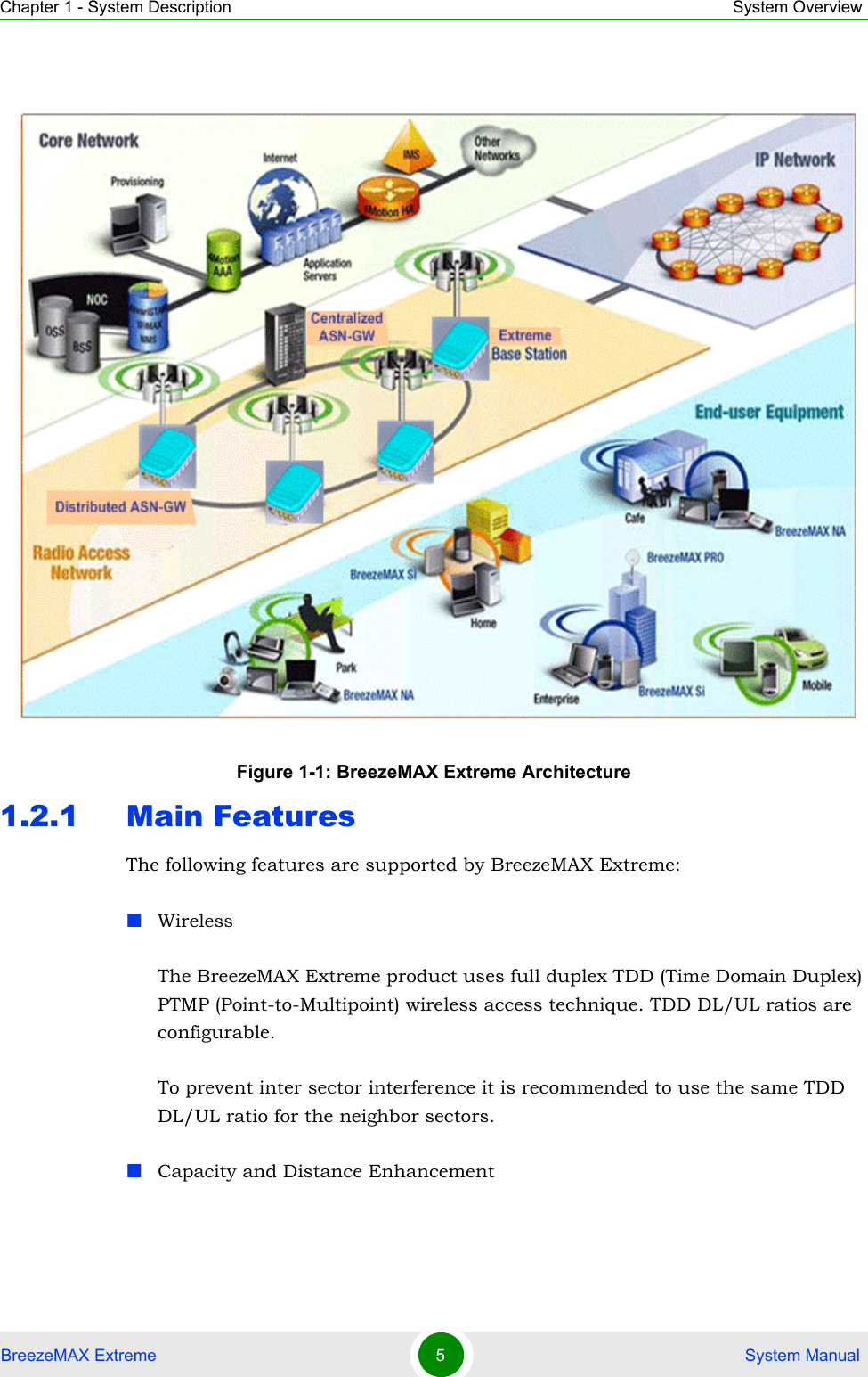
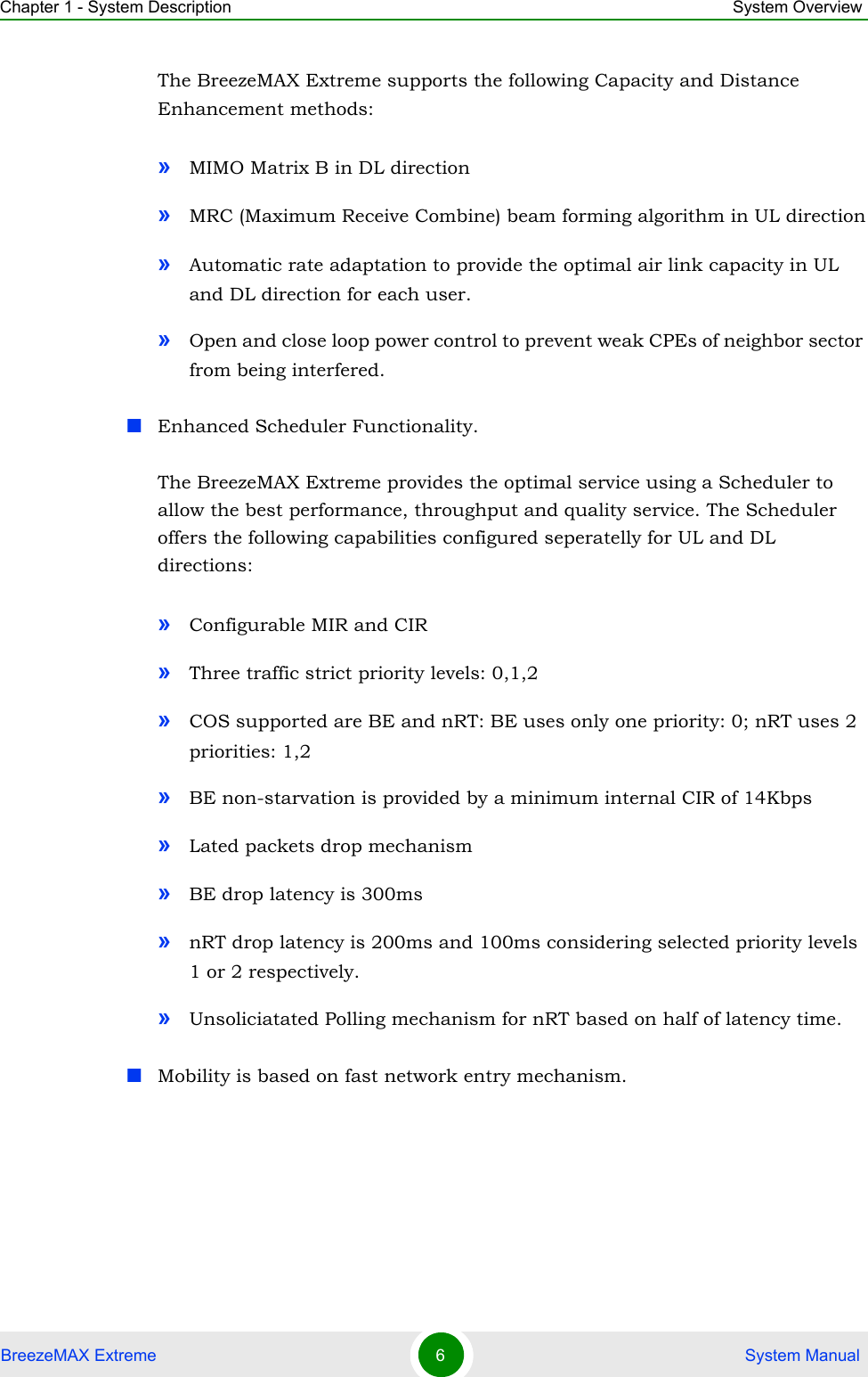
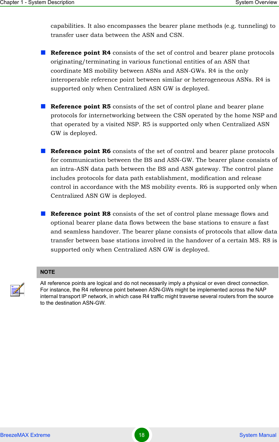
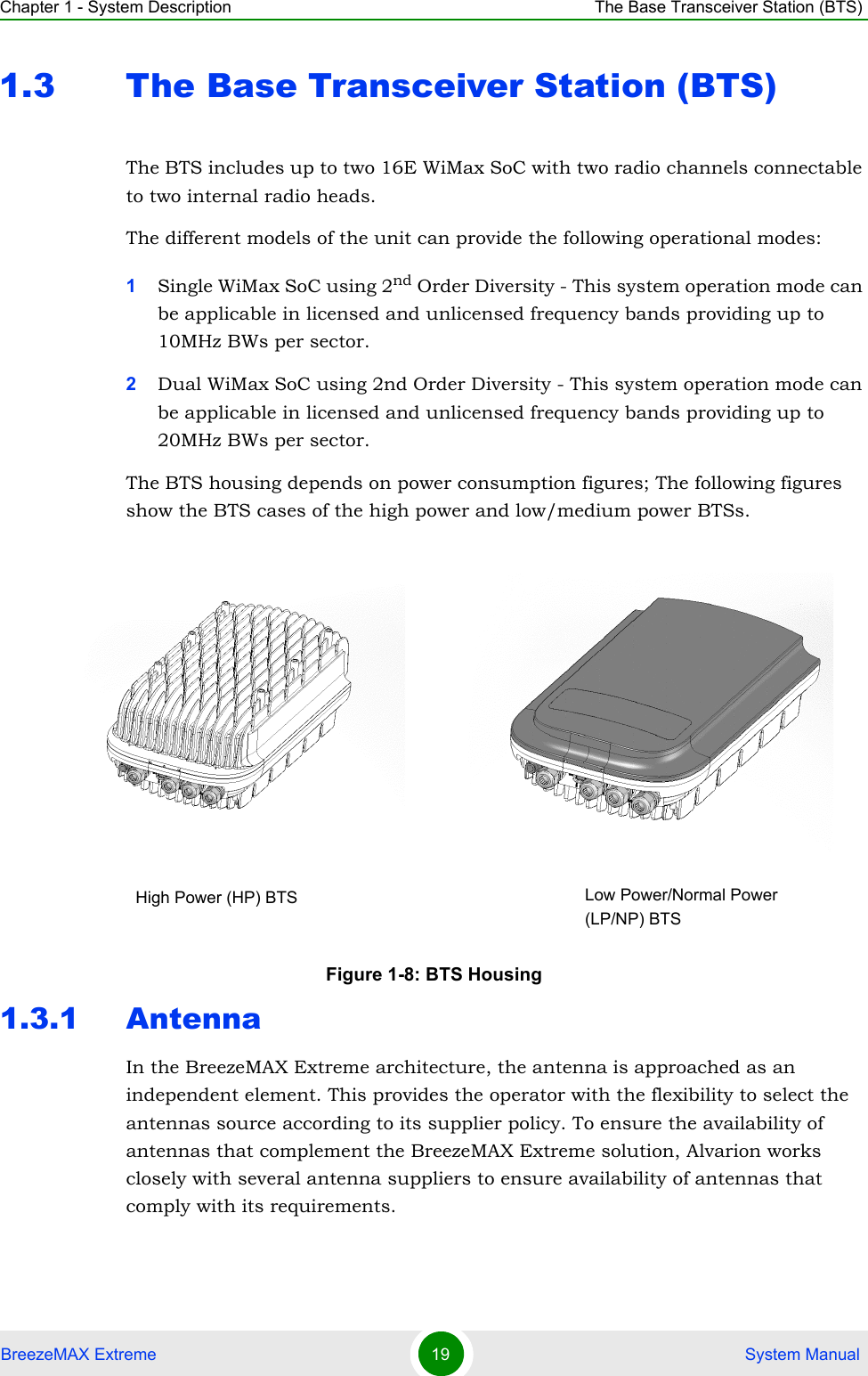
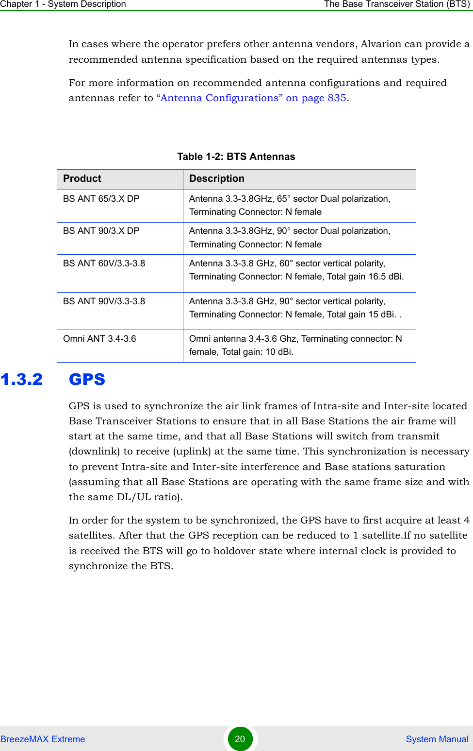
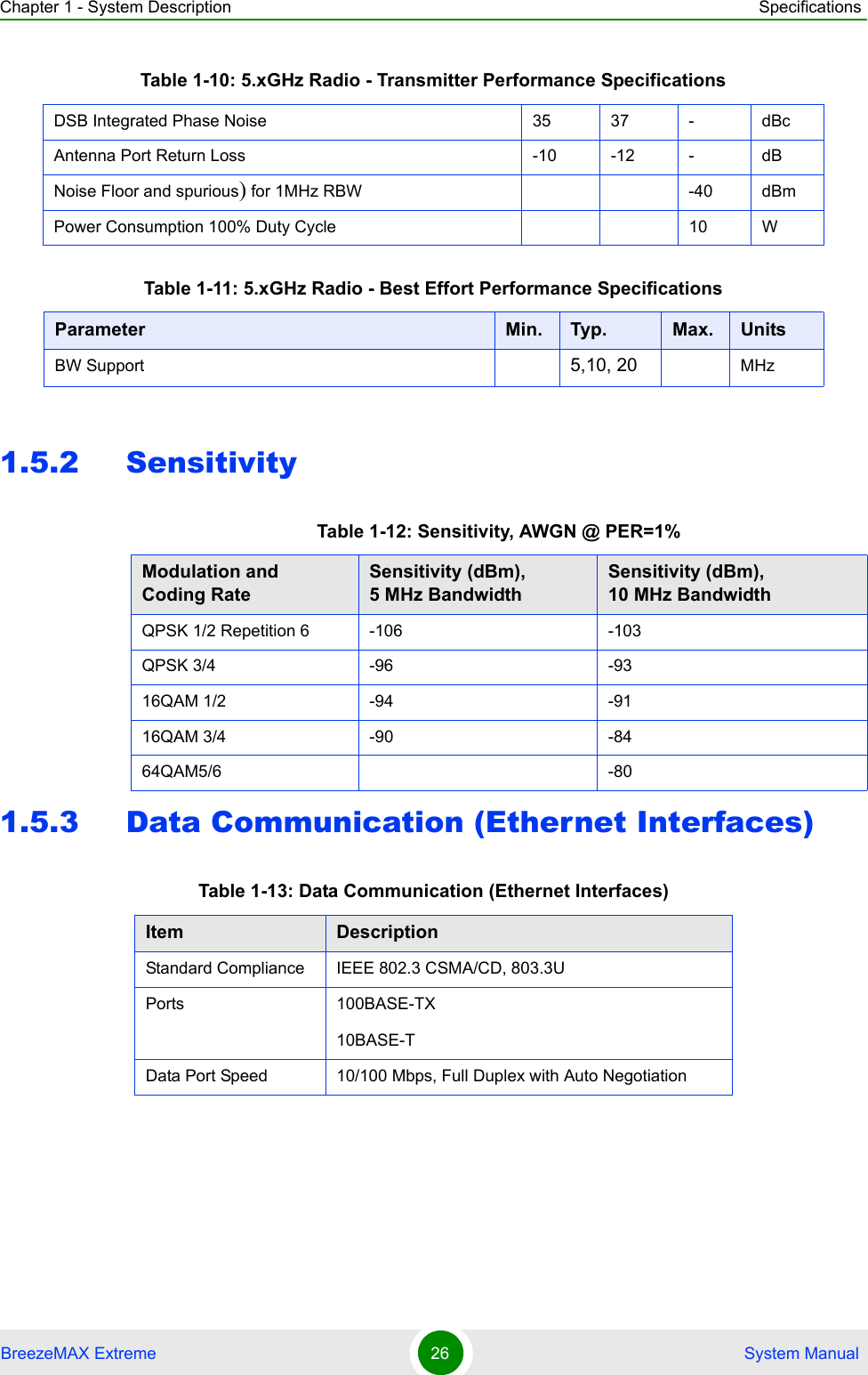
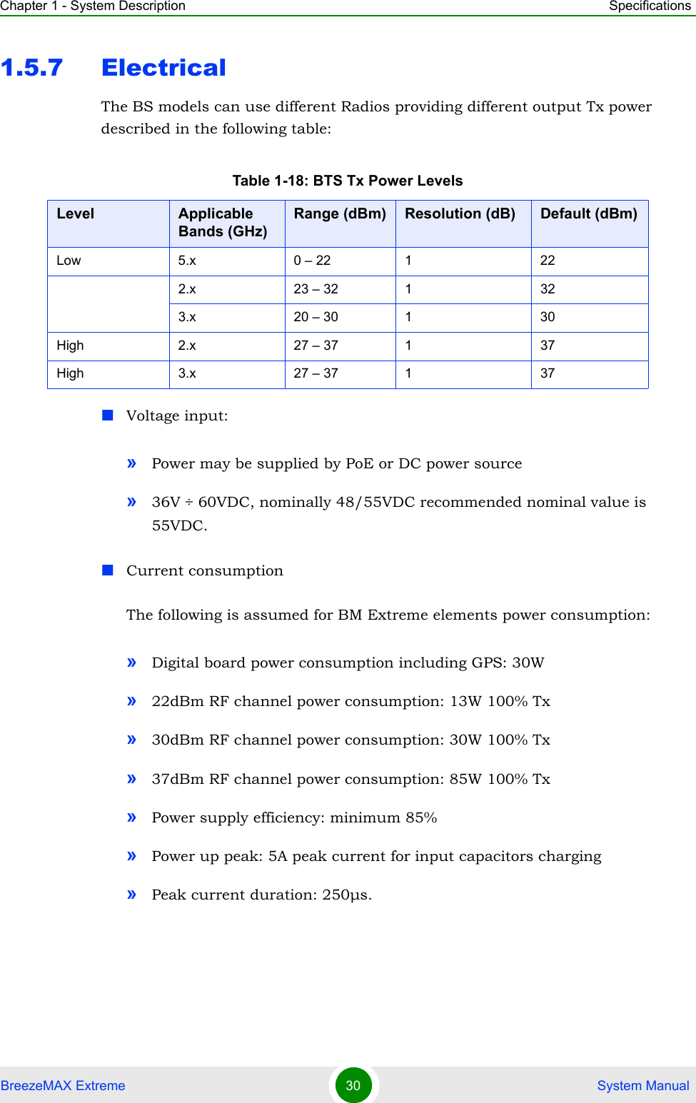
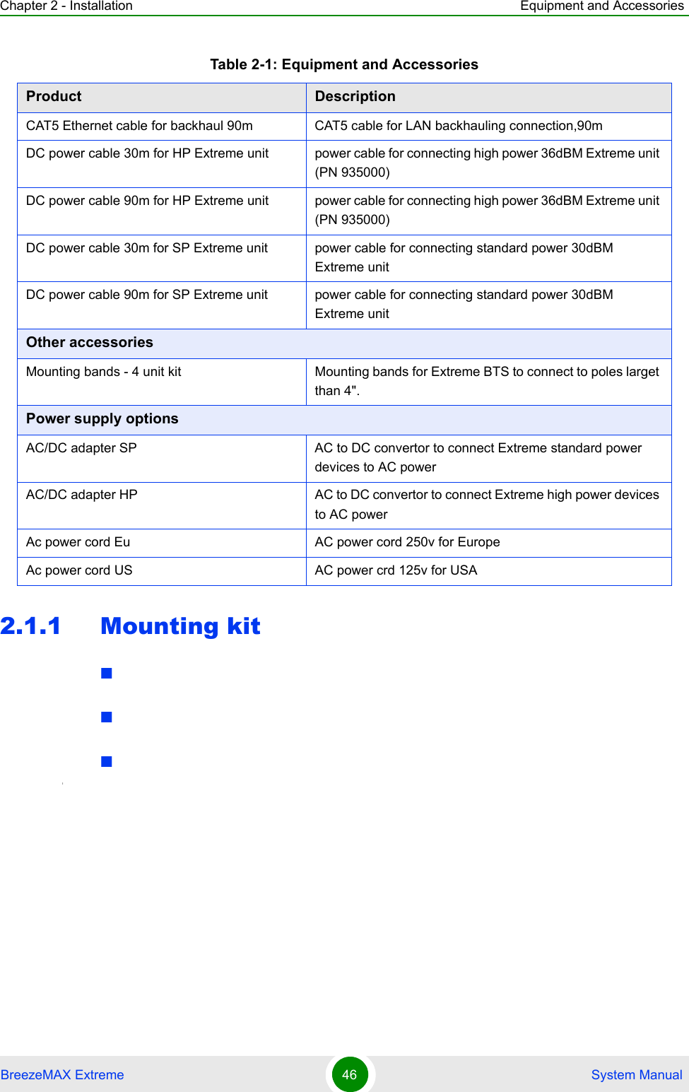
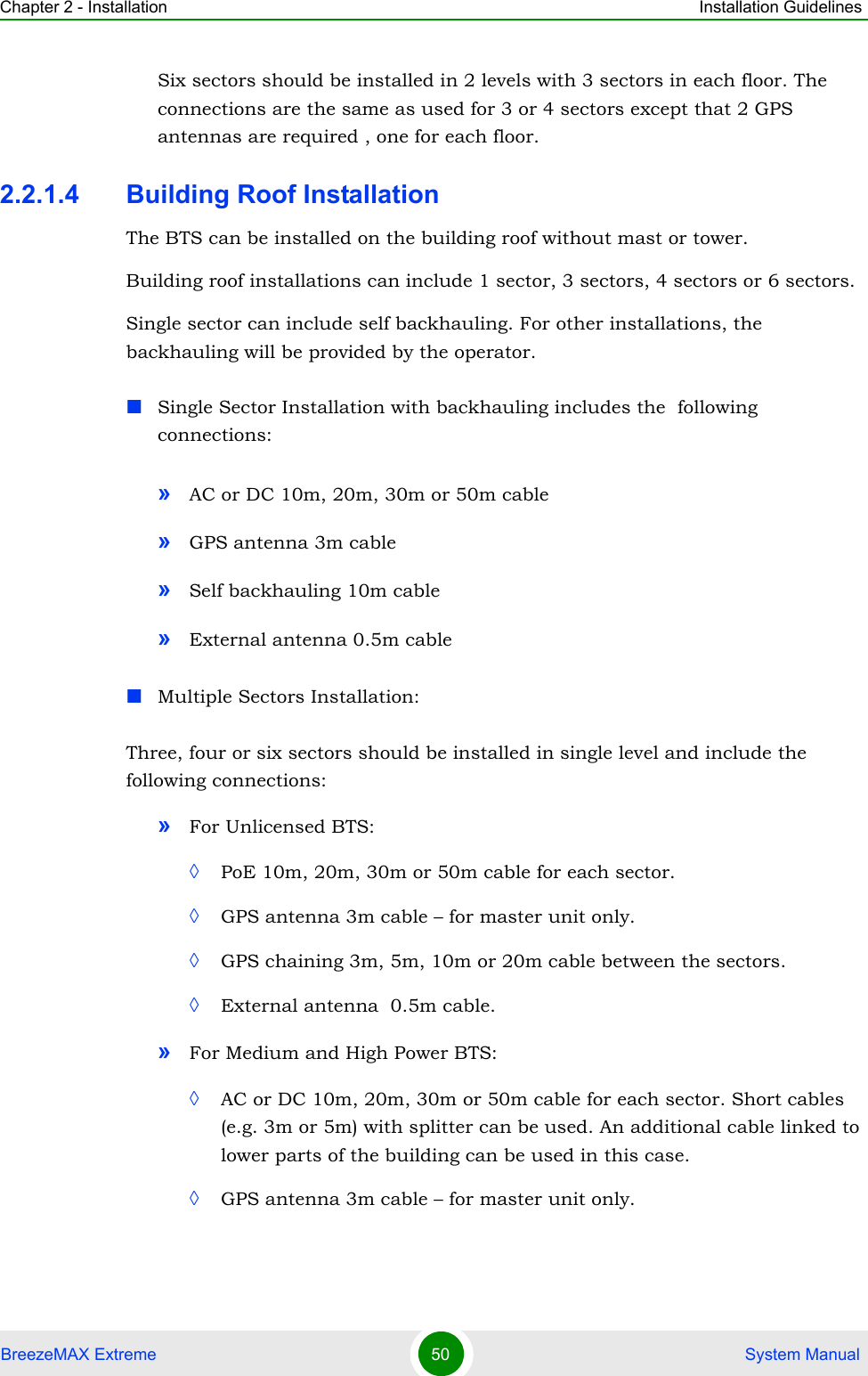
![Chapter 2 - Installation Installing GPSBreezeMAX Extreme 58 System Manual2.4 Installing GPS The GPS is connected to the GPS/SYNC IN connector. Before connecting the cable, make sure that the length of the cable is sufficient to reach the BTS.Mounting Kit:1Place the bracket on a flat surface and thread the supplied pipethrough the bracket hole and into the GPS antenna. Hand-tighten until snug. Do not over-tighten or use a tool. Make sure that the connector (male) is on the open side of the bracket.2Connect the interface cable to the antenna. hand-tighten the connector on the interface connector using the locking ring for securing the connection. Do not over-tighten to avoid stripping the connector.3Use the supplied clamps to assemble the GPS and bracket on a pole. Use the M8 nuts, washers, and spring washers to lock the clamps to the bracket. Apply torque 9 [N*m] (80 [lbs*in]).Table 2-2: GPS Mounting KitsItem DescriptionGPS Antenna kit- Normal Antenna3m cablePole mount bracket Mounting band GPS antenna kit - bullet Bullet antenna25m cablePole mount bracket Mounting band Lightning protectorsGPS chaning cable Cable to chain GPS signal between 2 colocated Extreme base stations To install the GPS:](https://usermanual.wiki/Alvarion-Technologies/EXTR-50.user-installation-manual/User-Guide-1100704-Page-65.png)