Alvarion Technologies IF-24 WLAN User Manual Updated
Alvarion Ltd. WLAN Updated
UserManual.wiki
>
Alvarion Technologies
>
IF-24 User Manual
>
Updated user manual
Contents
1.
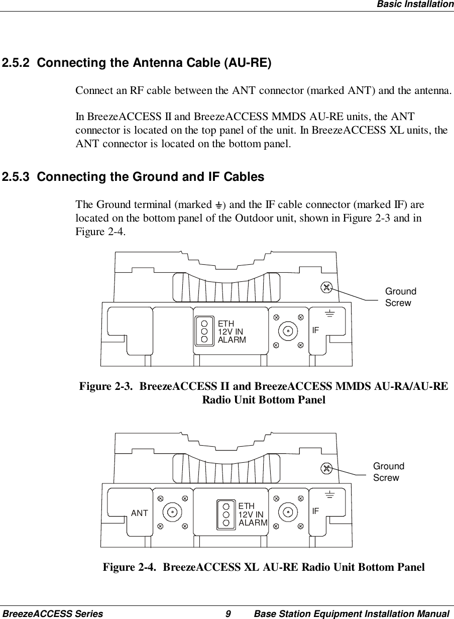
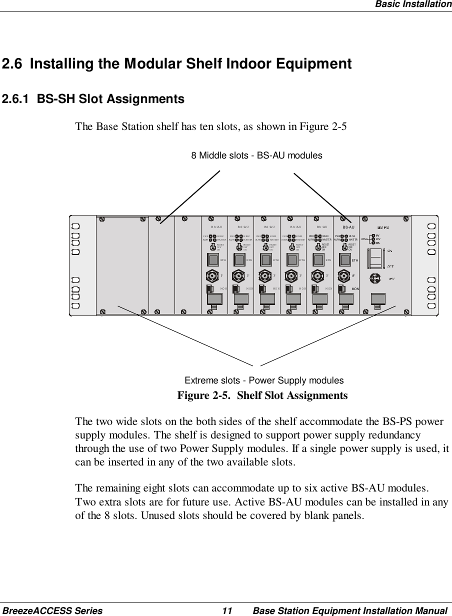
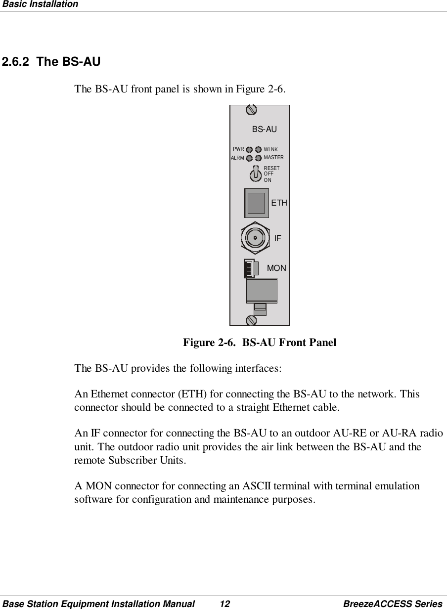
Base Station Manual
2.
Subscriber Unit Manual
3.
Updated user manual
Updated user manual
Navigation menu
Upload a User Manual
Namespaces
Wiki Guide
HTML
PDF
Info
Views
User Manual
Discussion / Help
Navigation
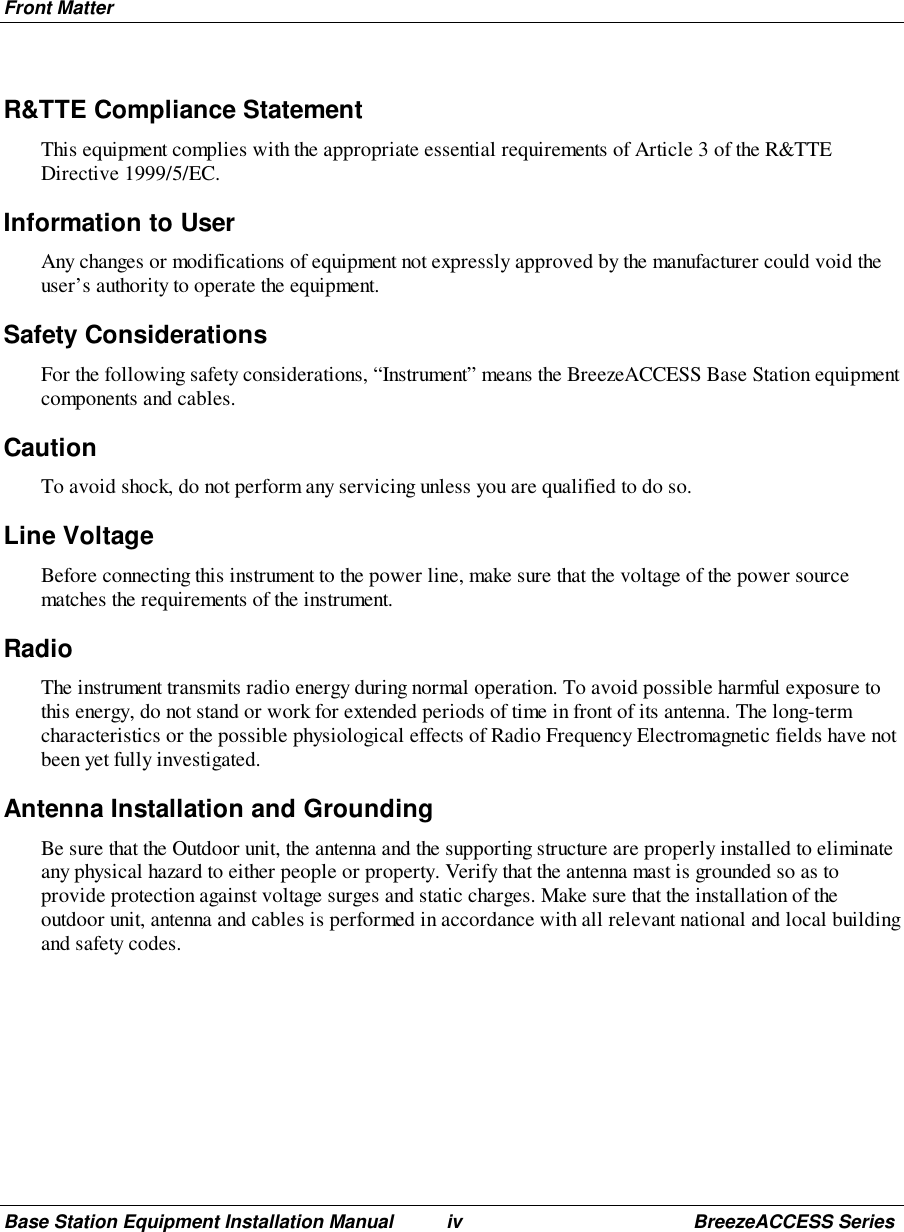
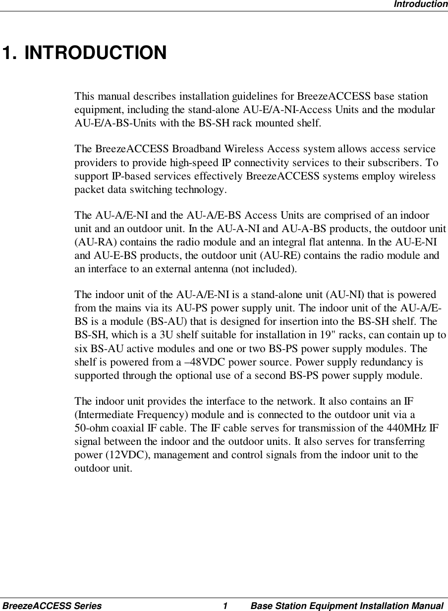
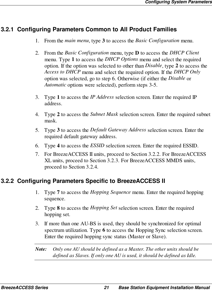
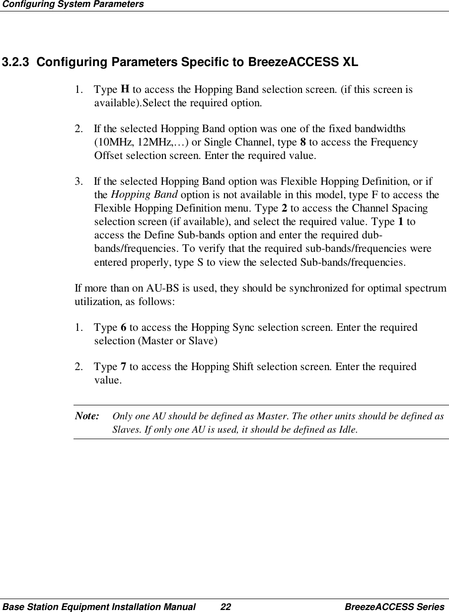
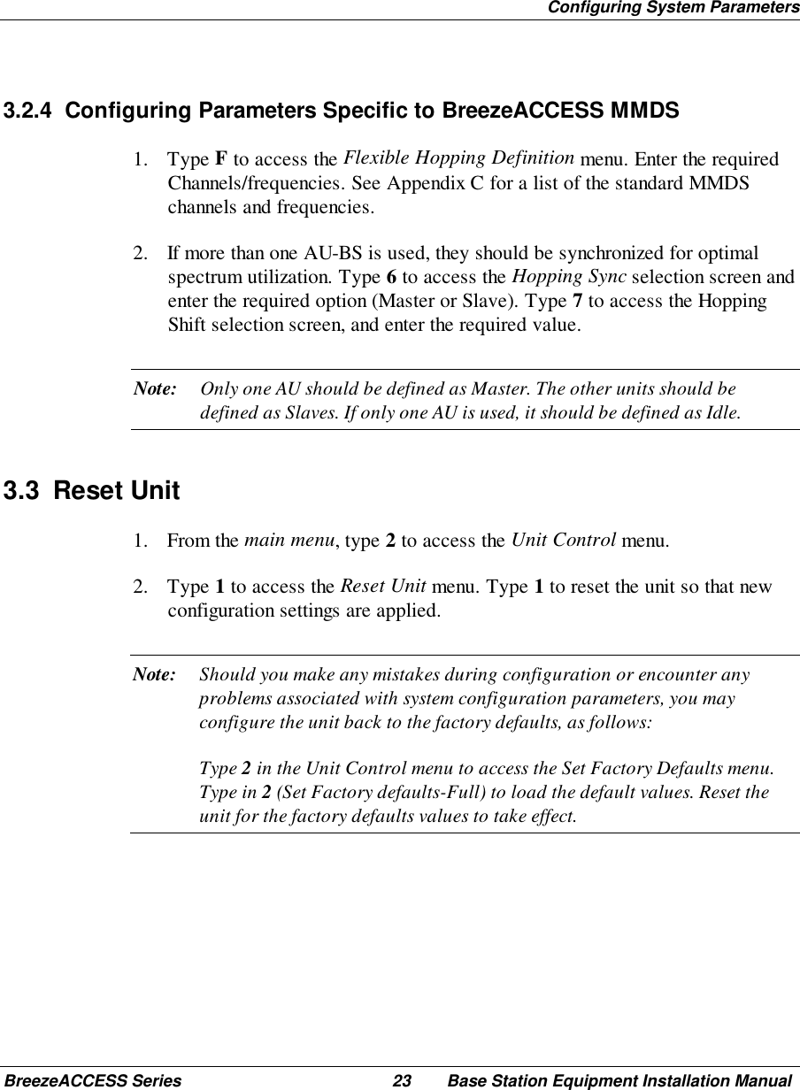
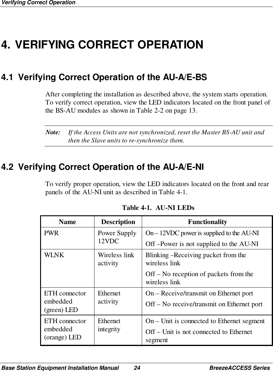
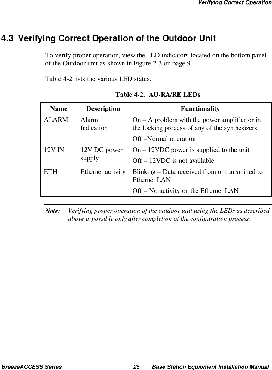
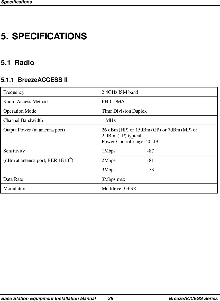
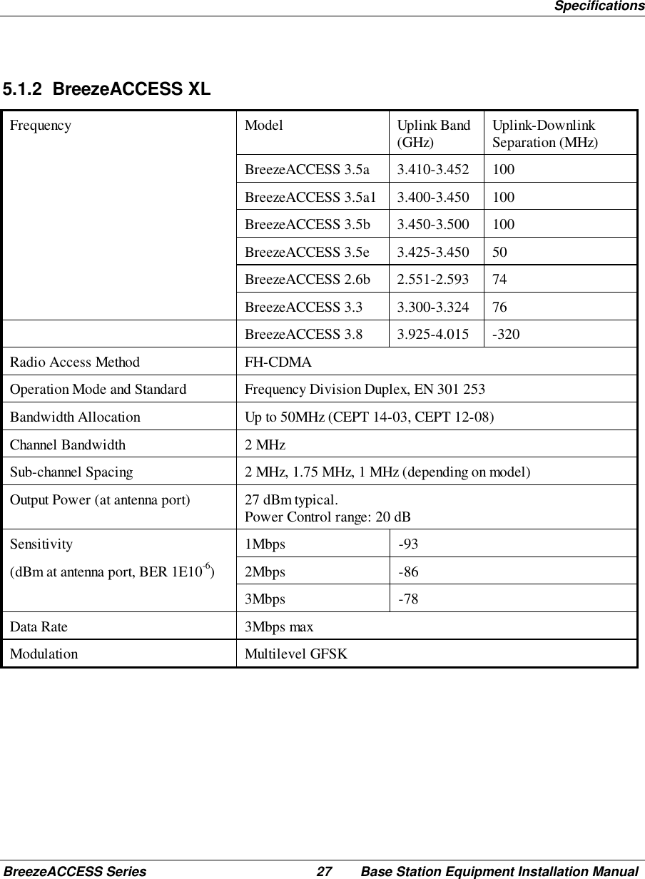
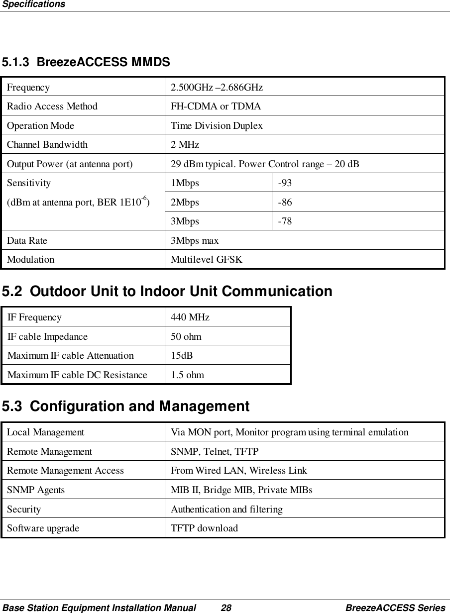
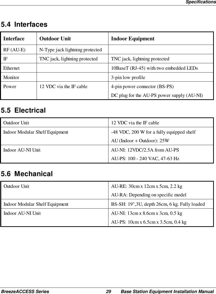
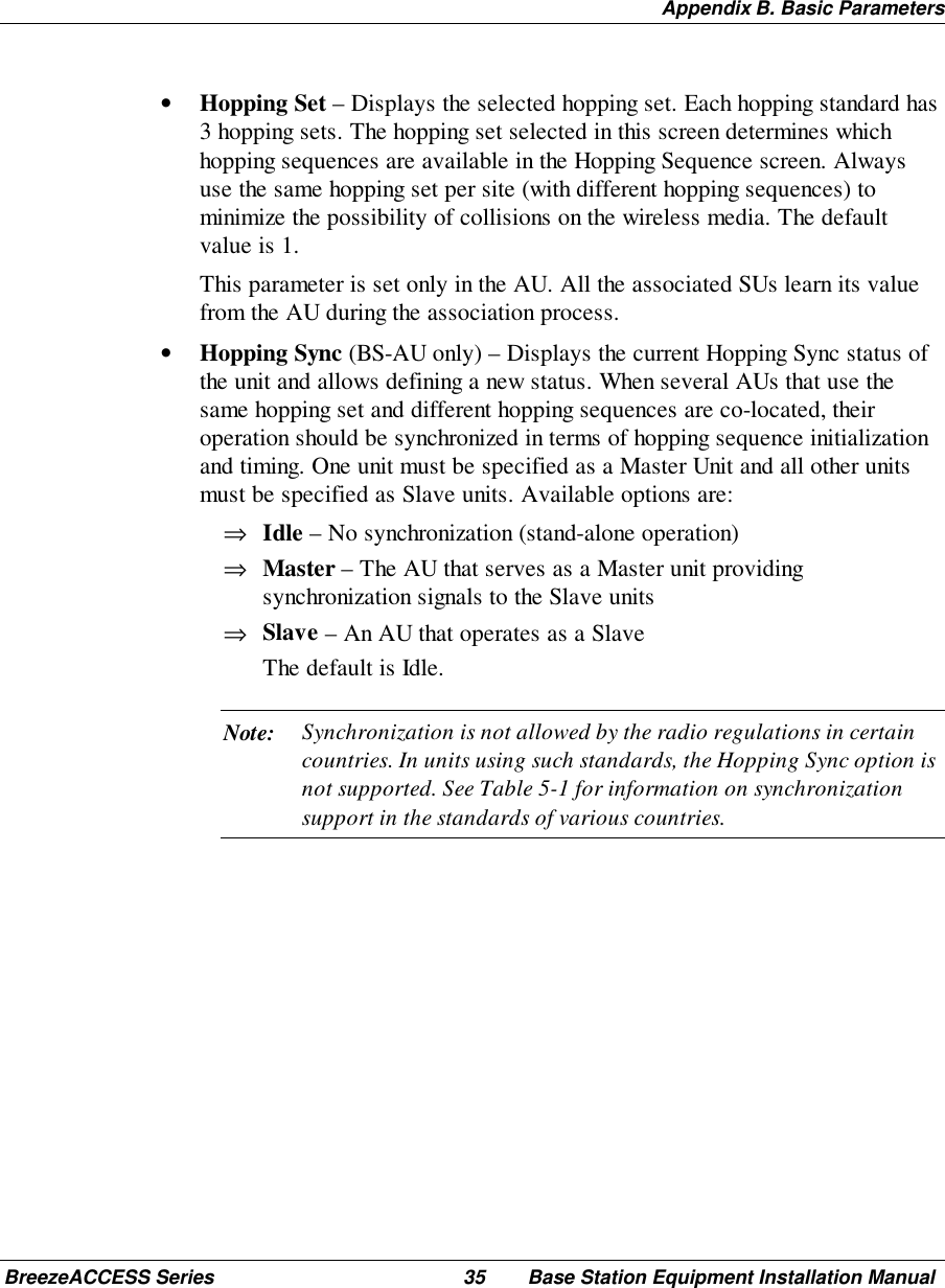
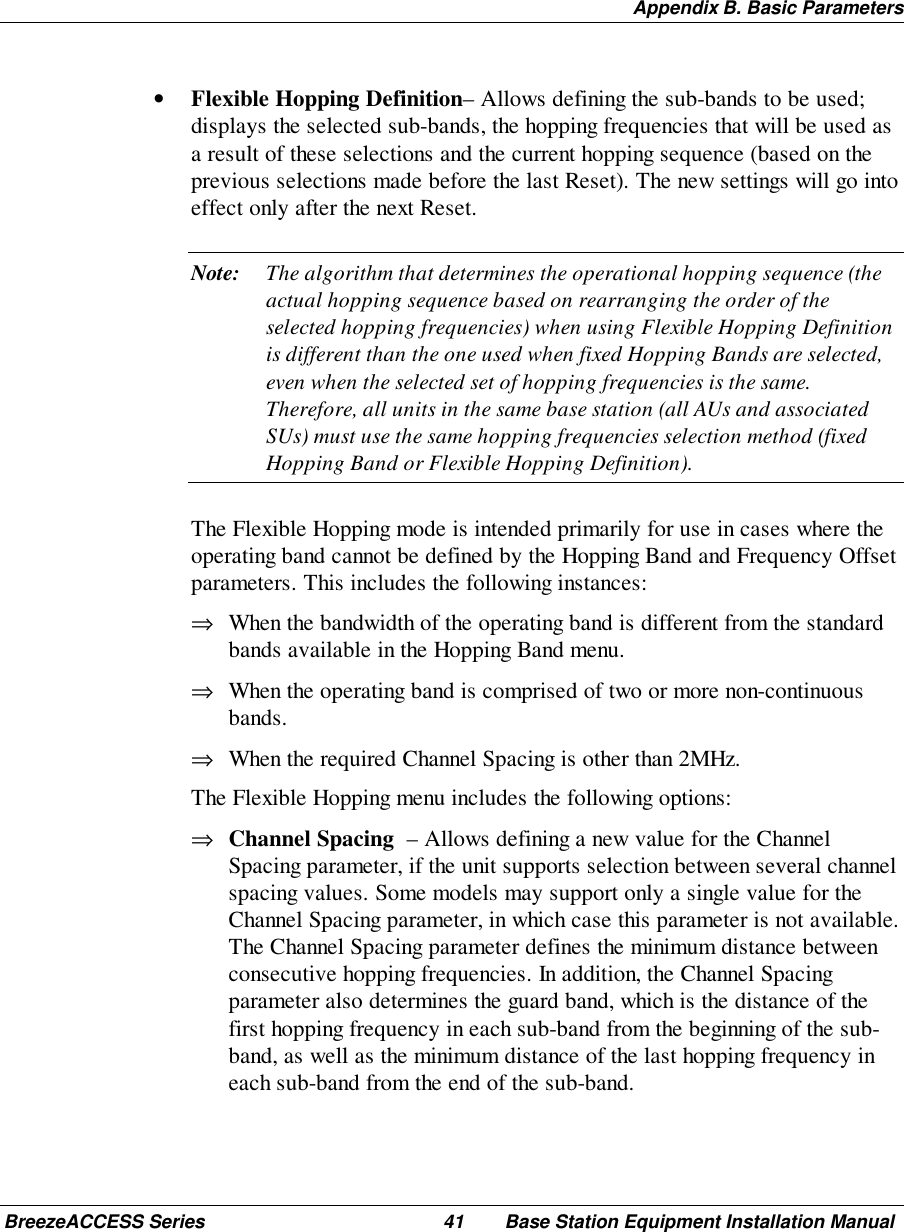
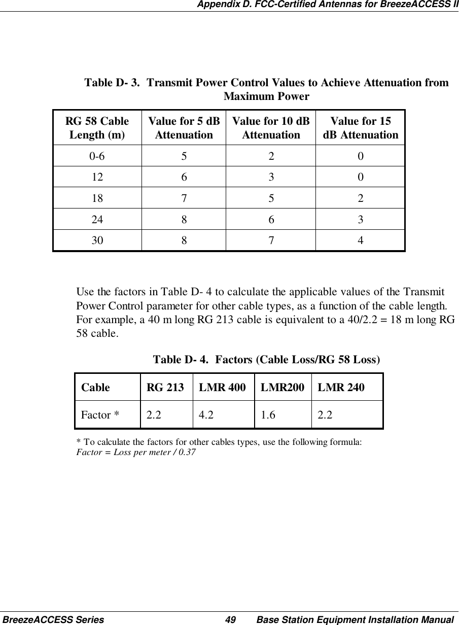
![Appendix B. Basic ParametersBase Station Equipment Installation Manual 36 BreezeACCESS SeriesTable 5-1. Country Standards Supported by BreezeACCESS IICountryStandard FrequencyRange [MHz] Number ofChannels HoppingSequencesper HoppingSetHoppingSyncSupportAustralia 2400 to 2463 60 20 NoCanada 2450 to 2483.5 30 10 NoEurope ETSI 2400 to 2483.5 79 26 YesFrance 2446 to 2483.5 35 11 YesIsrael 2418 to 2457 35 11 YesKorea 2427 to 2454 23 4 YesJapan 2470 to 2497or2400 to 2483.523or794or26YesNetherlands 2452 to 2470 15 5 YesSpain 2447 to 2473 27 9 YesUS FCC 2400 to 2483.5 79 26 NoMexico 2450 to 2483.5 30 10 YesRest of America 2400 to 2483.5 79 26 Yes](https://usermanual.wiki/Alvarion-Technologies/IF-24.Updated-user-manual/User-Guide-176504-Page-44.png)