Alvarion Technologies IF-24 WLAN User Manual Subscriber Unit Manual
Alvarion Ltd. WLAN Subscriber Unit Manual
UserManual.wiki
>
Alvarion Technologies
>
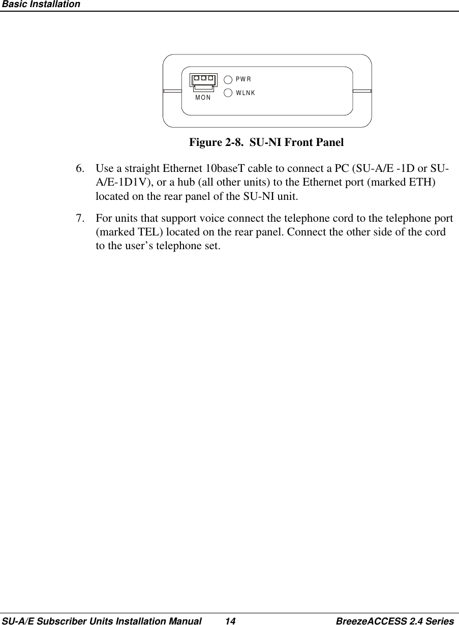
IF-24 User Manual
>
Subscriber Unit Manual
Contents
1.
Base Station Manual
2.
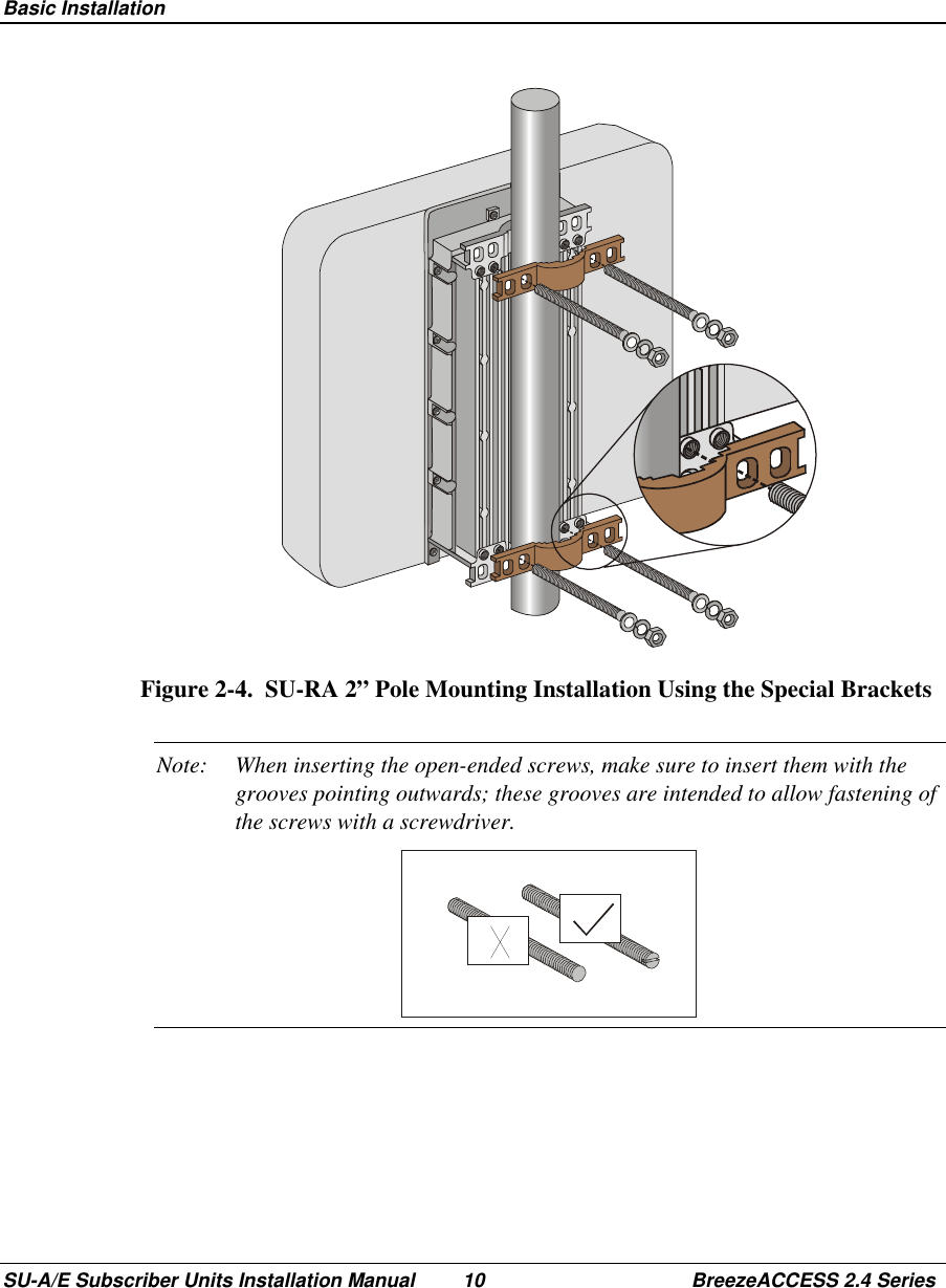
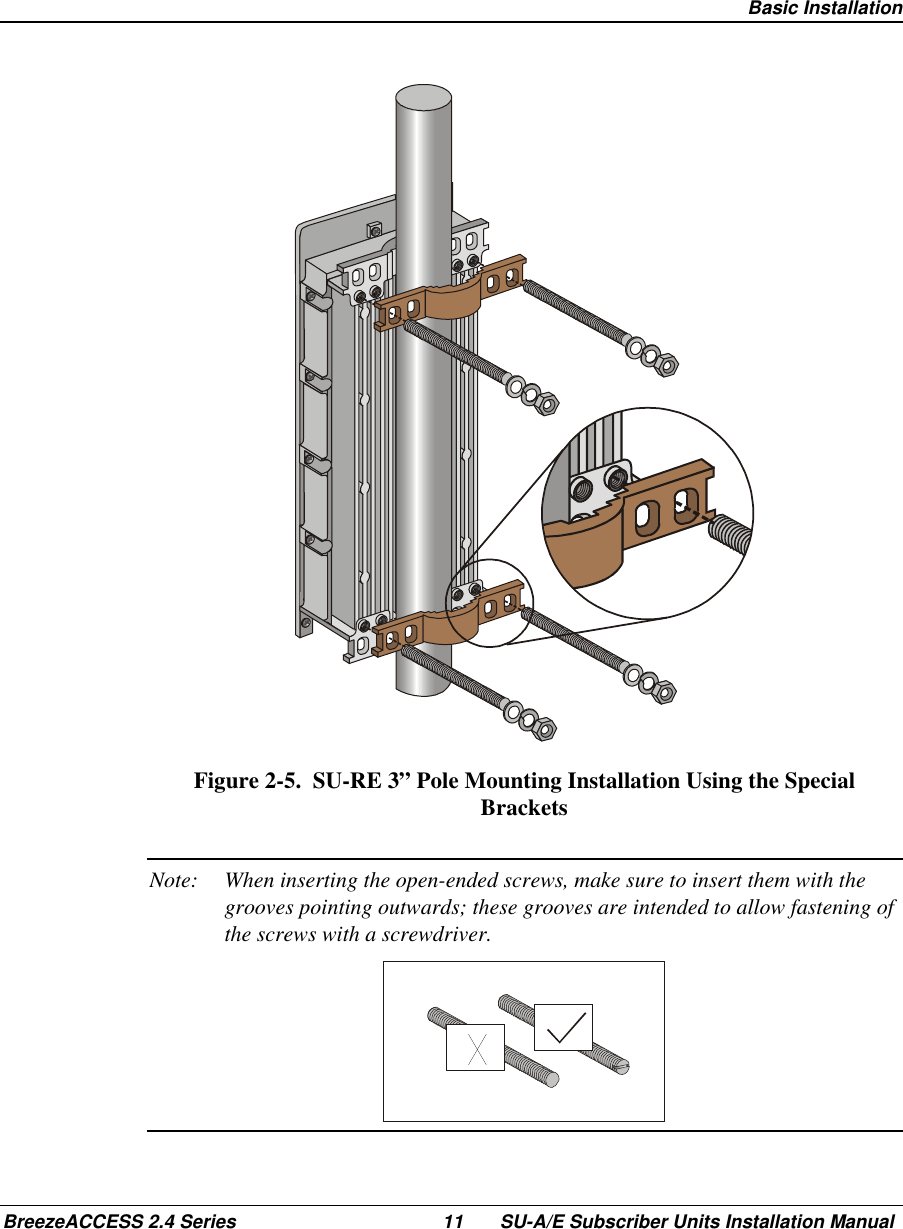
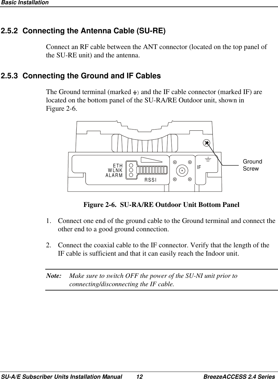
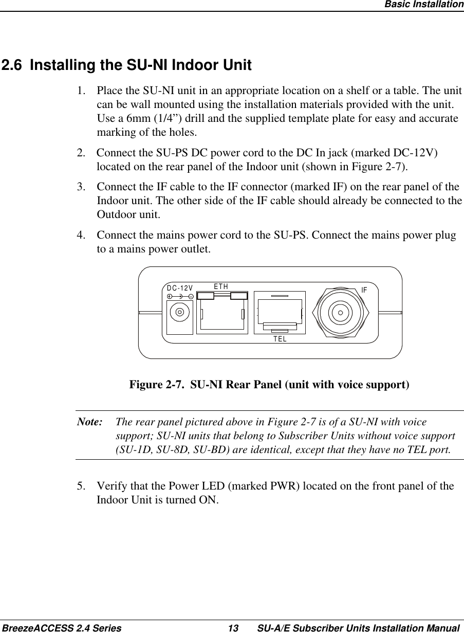
Subscriber Unit Manual
3.
Updated user manual
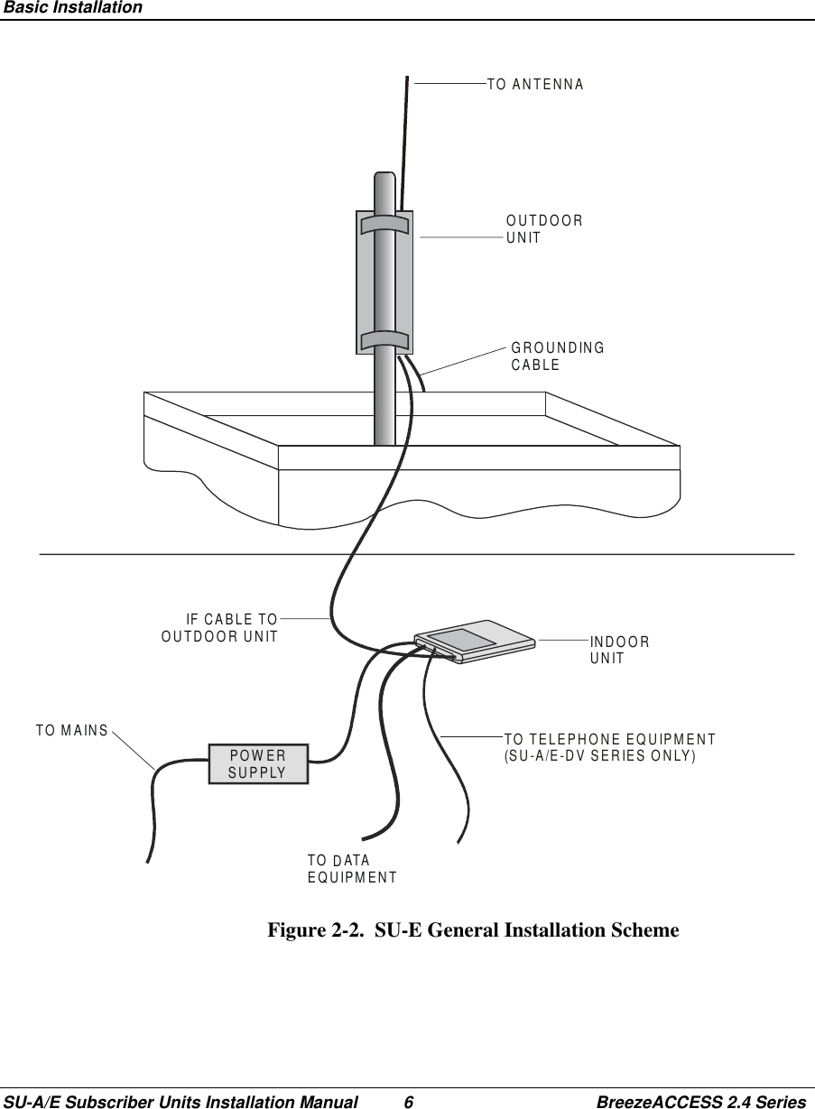
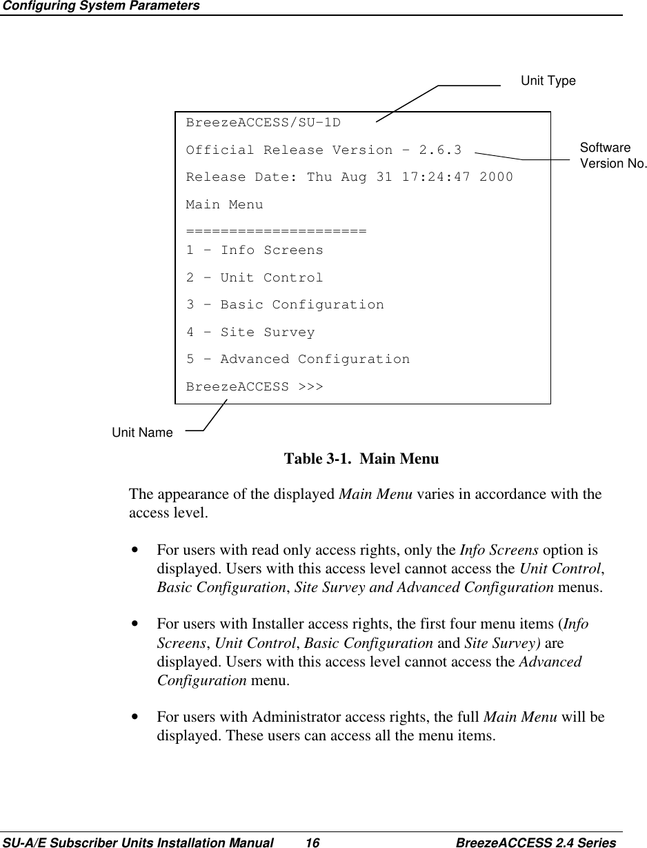
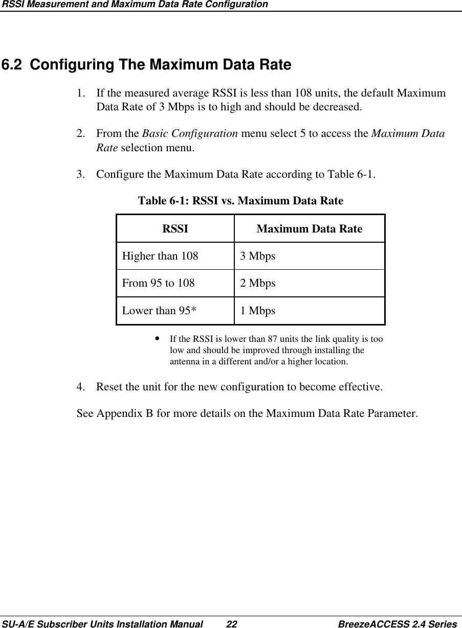
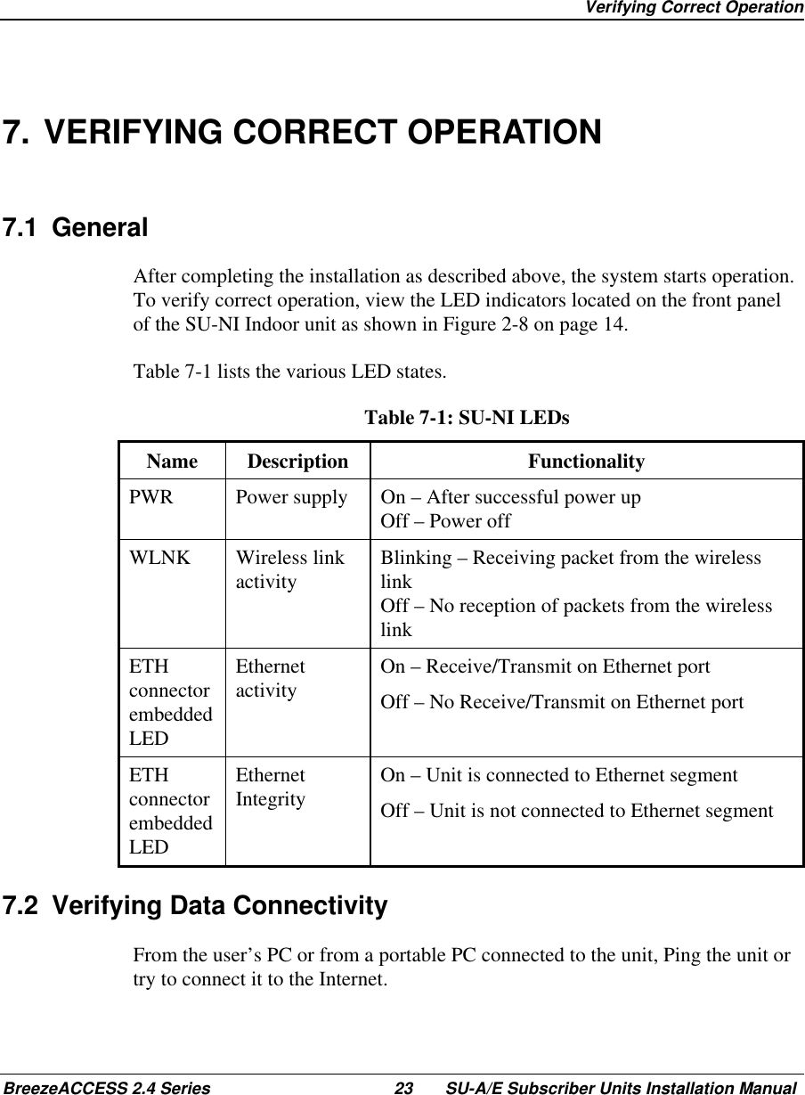
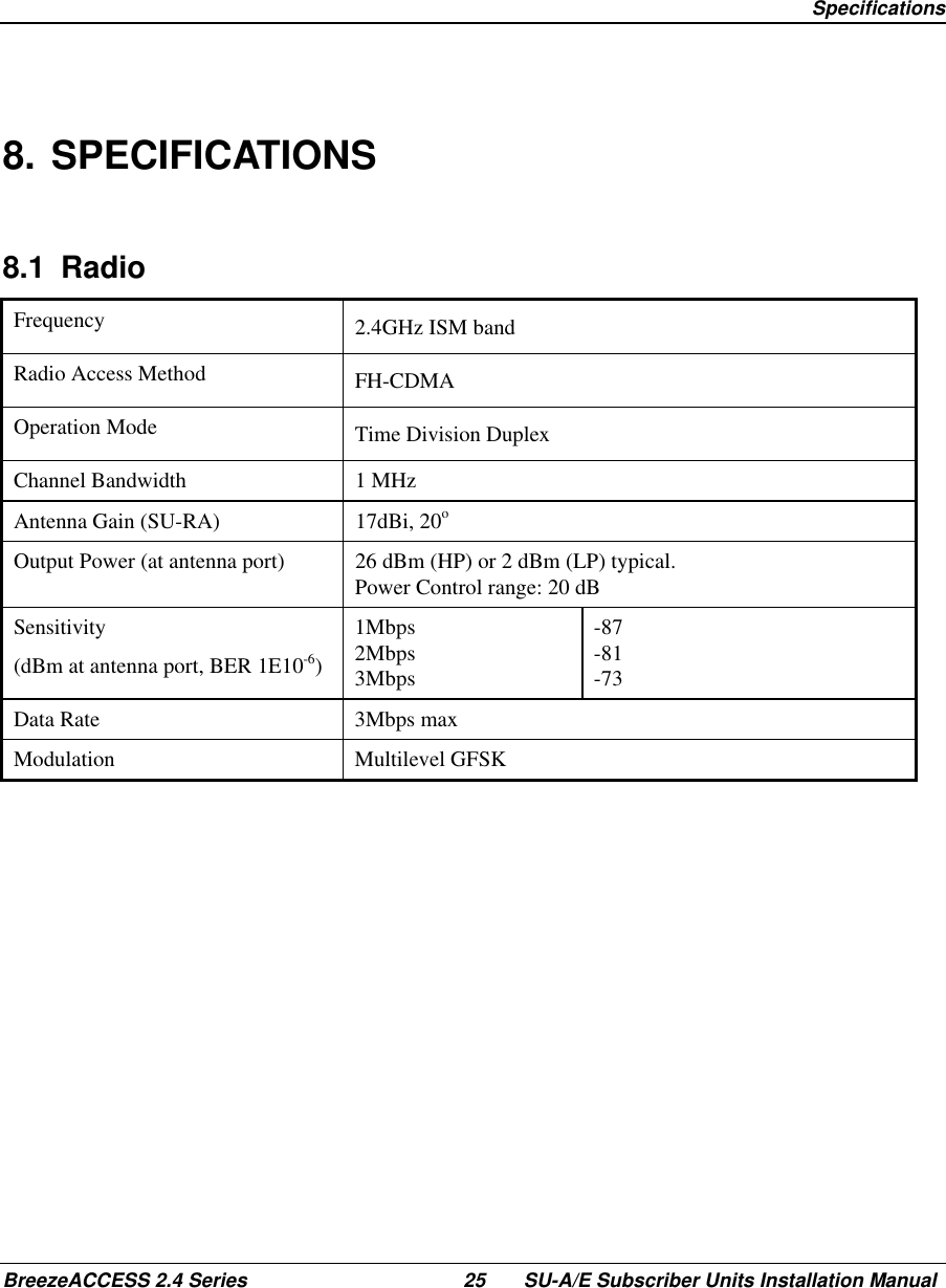
Subscriber Unit Manual
Navigation menu
Upload a User Manual
Namespaces
Wiki Guide
HTML
PDF
Info
Views
User Manual
Discussion / Help
Navigation