Alvarion Technologies IF-24 WLAN User Manual Subscriber Unit Manual
Alvarion Ltd. WLAN Subscriber Unit Manual
Contents
- 1. Base Station Manual
- 2. Subscriber Unit Manual
- 3. Updated user manual
Subscriber Unit Manual

BreezeACCESS 2.4
Subscriber Units
SU-A-2.4 Series
SU-E-2.4 Series
Installation
Manual
Preliminary
Revision 3
November, 2000
Cat. No. 213123

Front Matter
SU-A/E Subscriber Units Installation Manual ii BreezeACCESS 2.4 Series
© 2000 by BreezeCOM Ltd. All rights reserved.
No part of this publication may be reproduced in any material form without the written permission of
the copyright owner.
Trade Names
BreezeACCESS, BreezeNET, BreezeLINK, BreezeVIEW, BreezeMANAGE and WIX are trade
names of BreezeCOM Ltd. Other brand and product names are registered trademarks or trademarks of
their respective companies.
Statement of Conditions
The information contained in this manual is subject to change without notice. BreezeCOM shall not be
liable for errors contained herein or for incidental or consequential damages in connection with the
furnishing, performance, or use of this manual or equipment supplied with it.
Warranty
In the following warranty text, “the Company” shall mean:
• BreezeCOM Ltd., for products located outside the USA.
• BreezeCOM Inc., for products located in the USA.
This BreezeACCESS product is warranted against defects in material and workmanship for a period of
one year from date of purchase. During this warranty period the Company will, at its option, either
repair or replace products that prove to be defective.
For warranty service or repair, the product must be returned to a service facility designated by the
Company. Authorization to return products must be obtained prior to shipment. The buyer shall pay all
shipping charges to the Company and the Company shall pay shipping charges to return the product to
the buyer.
The Company warrants that the firmware designed by it for use with the unit will execute its
programming instructions when properly installed on the unit. The Company does not warrant that the
operation of the unit or firmware will be uninterrupted or error-free.
Limitations of Warranty
The foregoing warranty shall not apply to defects resulting from improper or inadequate maintenance
by the buyer, buyer supplied interfacing, unauthorized modification or misuse, operation outside of the
environmental specifications for the product, or improper site preparation or maintenance. No other
warranty is expressed or implied. The Company specifically disclaims the implied warranties of
merchantability and fitness for any particular purpose.
BreezeCOM shall not be liable to any person for any special or indirect damages, including, but not

Front Matter
BreezeACCESS 2.4 Series iii SU-A/E Subscriber Units Installation Manual
limited to, loss of profits or revenues, loss of use or damage to any associated equipment, cost of
capital, cost of substitute products, facilities or services, downtime costs or claims resulting from any
cause whatsoever arising from or in any way connected with the manufacture, sale, handling, service,
repair, maintenance or use of the products. In no event shall the company’s liability exceed the
purchase price denoted on the invoice.
Electronic Emission Notice
This device complies with Part 15 of the FCC rules. Operation is subject to the following two
conditions:
1. This device may not cause harmful interference.
2. This device must accept any interference received, including interference that may cause
undesired operation.
FCC Radio Frequency Interference Statement
This equipment has been tested and found to comply with the limits for digital equipment,
pursuant to Part 15 of the FCC rules. These limits are designed to provide reasonable protection
against harmful interference when the equipment is operated in a residential environment
notwithstanding use in commercial, business and industrial environments. This equipment generates,
uses, and can radiate radio frequency energy and, if not installed and used in accordance with the
instruction manual, may cause harmful interference to radio communications.
Information to User
Any changes or modifications of equipment not expressly approved by the manufacturer could void the
user’s authority to operate the equipment.
Safety Considerations
For the following safety considerations, “Instrument” means the BreezeACCESS Subscriber Unit
components and its cables. To avoid shock, do not perform any servicing unless you are qualified.
RF Warning
To comply with FCC RF exposure requirements in section 1.1307, a minimum separation distance of
2m (79 inches) is required between the antenna and all persons.
Line Voltage
Before connecting this instrument to the power line, make sure that the voltage of the power source
matches the requirements of the instrument.

Front Matter
SU-A/E Subscriber Units Installation Manual iv BreezeACCESS 2.4 Series
Radio
The instrument transmits radio energy during normal operation. To avoid possible harmful exposure to
this energy, do not stand or work for extended periods of time in front of its antenna. The long-term
characteristics or the possible physiological effects of Radio Frequency Electromagnetic fields have
not been yet fully investigated.
Antenna Installation and Grounding
Be sure that the Outdoor unit, the antenna and the supporting structure are properly installed to
eliminate any physical hazard to either people or property. Verify that the antenna mast is grounded so
as to provide protection against voltage surges and static charges. Make sure that the installation of the
Outdoor unit, antenna and cables is performed in accordance with all relevant national and local
building and safety codes.

BreezeACCESS 2.4 Series v SU-A/E Subscriber Units Installation Manual
Table of Contents
1. INTRODUCTION .....................................................................................................................1
2. BASIC INSTALLATION..........................................................................................................4
2.1 Packing List...........................................................................................................................4
2.2 Other Items Required for Installation....................................................................................4
2.3 General Installation Scheme..................................................................................................5
2.4 Guidelines for Selection of Equipment Locations ................................................................7
2.5 Installing the Outdoor Unit ...................................................................................................9
2.5.1 Pole Mounting the Outdoor Unit ...................................................................................9
2.5.2 Connecting the Antenna Cable (SU-RE) .....................................................................12
2.5.3 Connecting the Ground and IF Cables.........................................................................12
2.6 Installing the SU-NI Indoor Unit.........................................................................................13
3. CONFIGURING SYSTEM PARAMETERS........................................................................15
3.1 Getting Started with the Local Terminal.............................................................................15
3.2 Configuring Basic Parameters.............................................................................................17
3.3 Reset Unit............................................................................................................................18
4. ALIGNING THE ANTENNA.................................................................................................19
5. VERIFYING CORRECT OPERATION OF THE OUTDOOR UNIT..............................20
6. RSSI MEASUREMENT AND MAXIMUM DATA RATE CONFIGURATION .............21
6.1 Performing the RSSI Measurement.....................................................................................21
6.2 Configuring The Maximum Data Rate................................................................................22

Table of Contents
SU-A/E Subscriber Units Installation Manual vi BreezeACCESS 2.4 Series
7. VERIFYING CORRECT OPERATION ..............................................................................23
7.1 General ................................................................................................................................23
7.2 Verifying Data Connectivity ...............................................................................................23
7.3 Verifying Telephone Connectivity (SU-A/E-DV series only)............................................24
8. SPECIFICATIONS .................................................................................................................25
8.1 Radio ...................................................................................................................................25
8.2 Data Communication...........................................................................................................26
8.3 Voice Communication (SU-A/E-DV series).......................................................................26
8.4 Outdoor Unit to Indoor Unit Communication.....................................................................26
8.5 Configuration and Management..........................................................................................26
8.6 Interfaces .............................................................................................................................27
8.7 Electrical, Mechanical and Environmental .........................................................................27
8.8 Standards Compliance, General ..........................................................................................27
APPENDIX A. USING TELNET...............................................................................................28
APPENDIX B. BASIC PARAMETERS....................................................................................29

Table of Contents
BreezeACCESS 2.4 Series vii SU-A/E Subscriber Units Installation Manual
Table of Figures
Figure 2-1: SU-A General Installation Scheme.........................................................................5
Figure 2-2. SU-E General Installation Scheme .........................................................................6
Figure 2-3. Holes/Grooves/Screw holes....................................................................................9
Figure 2-4. SU-RA 2” Pole Mounting Installation Using the Special Brackets......................10
Figure 2-5. SU-RE 3” Pole Mounting Installation Using the Special Brackets......................11
Figure 2-6. SU-RA/RE Outdoor Unit Bottom Panel...............................................................12
Figure 2-7. SU-NI Rear Panel (unit with voice support).........................................................13
Figure 2-8. SU-NI Front Panel ................................................................................................14
Table of Tables
Table 1-1. BreezeACCESS SU-A-xD-2.4 Data Subscriber Units ............................................2
Table 1-2. BreezeACCESS SU-E-xD-2.4 Data Subscriber Units.............................................2
Table 1-3. BreezeACCESS SU-A-xD1V-2.4 Data Subscriber Units........................................3
Table 1-4. BreezeACCESS SU-E-xD1V-2.4 Data Subscriber Units........................................3
Table 3-1. Main Menu.............................................................................................................16
Table 5-1: SU-RA/RE Outdoor Unit LEDs.............................................................................20
Table 6-1: RSSI vs. Maximum Data Rate ................................................................................22
Table 7-1: SU-NI LEDs............................................................................................................23


Introduction
BreezeACCESS 2.4 Series 1 SU-A/E Subscriber Units Installation Manual
1. INTRODUCTION
This manual describes installation guidelines for BreezeACCESS 2.4 SU-A and
SU-E series of Subscriber Units.
The BreezeACCESS IP Broadband Wireless Local Loop (WLL) system allows
access service providers to provide high-speed IP connectivity services to their
subscribers. To effectively support IP-based services BreezeACCESS systems
employ wireless packet data switching technology.
The BreezeACCESS 2.4 line of products uses Frequency Hopping Spread
Spectrum radios that operate in Time Division Duplex (TDD) mode in the
2.400GHz – 2.500GHz frequency range.
SU-A and SU-E series Subscriber Units are comprised of an indoor unit (SU-NI)
and an outdoor unit. In the SU-A product line, the outdoor unit (SU-RA)
contains the radio module and an integral flat antenna. In the SU-E series, the
outdoor unit (SU-RE) contains the radio module and an interface to an external
antenna (not included). The indoor unit provides the interface to the user’s
equipment and is powered from the mains via its SU-PS power supply unit. The
SU-NI also contains an IF (Intermediate Frequency) module and is connected to
the outdoor unit via a 50-ohm coaxial IF cable. The IF cable serves for
transmission of the 440MHz IF signal between the indoor and the outdoor units.
It also serves for transferring power (12VDC), management and control signals
from the indoor unit to the outdoor unit.
Introduction
SU-A/E Subscriber Units Installation Manual 2 BreezeACCESS 2.4 Series
Table 1-1 lists the products included in the BreezeACCESS SU-A-xD-2.4 Data
Subscriber Units.
Table 1-2 lists the products included in the BreezeACCESS SU-E-xD-2.4 Data
Subscriber Units.
Table 1-3 lists the products included in the BreezeACCESS SU-A-xD1V-2.4
Data and Voice Subscriber Units.
Table 1-4 lists the products included in the BreezeACCESS SU-E-xD1V-2.4
Data and Voice Subscriber Units.
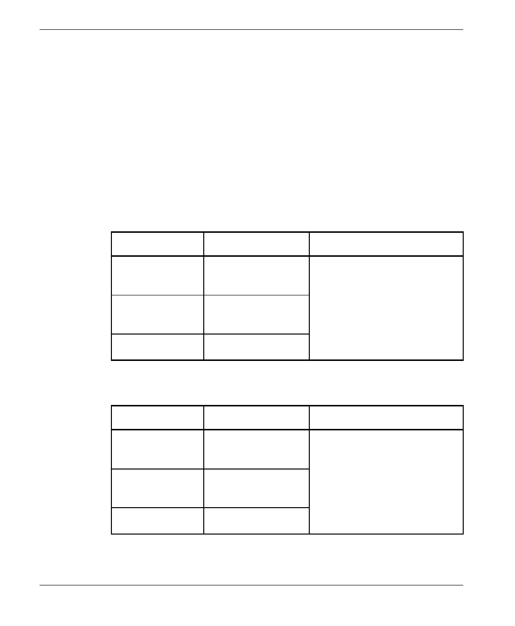
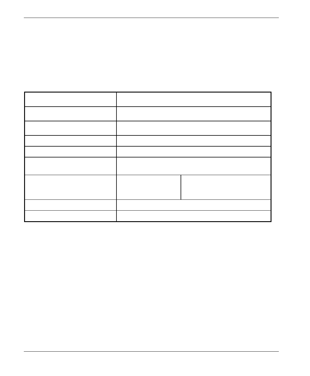
Table 1-1. BreezeACCESS SU-A-xD-2.4 Data Subscriber Units
Product CPE support General Description
SU-A-1D-HP-2.4
SU-A-1D-LP-2.4 Supports a single
Ethernet device. Indoor unit, power supply and an
outdoor radio unit with an
integral flat antenna.
SU-A-8D-HP-2.4
SU-A-8D-LP-2.4 Supports up to eight
Ethernet
workstations/PCs
Output power at antenna port:
26 dBm (SU-A-xD-HP-2.4) or
2 dBm (SU-A-xD-LP-2.4)
SU-A-BD-HP-2.4
SU-A-BD-LP-2.4 Supports a LAN
(bridge functionality)
Table 1-2. BreezeACCESS SU-E-xD-2.4 Data Subscriber Units
Product CPE support General Description
SU-E-1D-HP-2.4
SU-E-1D-LP-2.4 Supports a single
Ethernet device Indoor unit, power supply and an
outdoor radio unit with an RF
connector to an external antenna.
SU-E-8D-HP-2.4
SU-E-8D-LP-2.4 Supports up to eight
Ethernet
workstations/PCs
Output power at antenna port:
26 dBm (SU-E-xD-HP-2.4) or
2 dBm (SU-E-xD-LP-2.4)
SU-E-BD-HP-2.4
SU-E-BD-LP-2.4 Supports a LAN
(bridge functionality)
Introduction
BreezeACCESS 2.4 Series 3 SU-A/E Subscriber Units Installation Manual
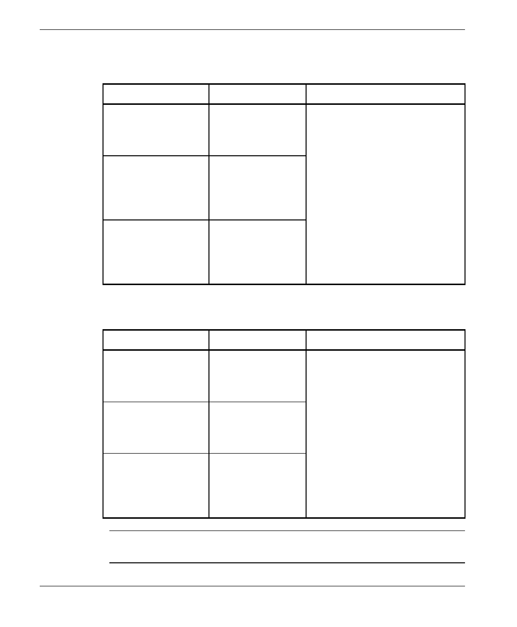
Table 1-3. BreezeACCESS SU-A-xD1V-2.4 Data and Voice Subscriber Units
Product CPE support General Description
SU-A-1D1V-HP-2.4
SU-A-1D1V-LP-2.4 Supports a single
Ethernet device and
a regular telephone
interface.
Indoor unit, power supply and an
outdoor radio unit with an
integral flat antenna.
Output power at antenna port:
SU-A-8D1V-HP-2.4
SU-A-8D1V-LP-2.4 Supports up to
eight Ethernet
workstations/PCs
and a regular
telephone interface.
26 dBm (SU-A-xD1V-HP-2.4) or
2 dBm (SU-A-xD1V-LP-2.4)
SU-A-BD1V-HP-2.4
SU-A-BD1V-LP-2.4 Supports a LAN
(bridge
functionality) and a
regular telephone
interface.
Table 1-4. BreezeACCESS SU-E-xD1V-2.4 Data and Voice Subscriber Units
Product CPE support General Description
SU-E-1D1V-HP-2.4
SU-E-1D1V-LP-2.4 Supports a single
Ethernet device and
a regular telephone
interface.
Indoor unit, power supply and an
outdoor radio unit with an RF
connector to an external antenna.
Output power at antenna port:
SU-E-8D1V-HP-2.4
SU-E-8D1V-LP-2.4 Supports up to
eight Ethernet and
a regular telephone
interface.
26dBm (SU-E-xD1V-HP-2.4) or
2dBm (SU-E-xD1V- LP-2.4)
SU-E-BD1V-HP-2.4
SU-E-BD1V-LP-2.4 Supports a LAN
(bridge
functionality) and a
regular telephone
interface.
Note: The information contained in this manual is applicable to BreezeACCESS 2.4
units with software release 2.5 and up.

Basic Installation
SU-A/E Subscriber Units Installation Manual 4 BreezeACCESS 2.4 Series
2. BASIC INSTALLATION
2.1 Packing List
• SU-NI Indoor unit
• Outdoor unit
⇒ SU-RA with integral antenna
or
⇒ SU-RE with a connector to an external antenna (not included)
• SU-PS power supply with a mains power cord
• Pole mounting kit for the Outdoor unit (with two brackets, four sets of
screws, nuts and washers)
• Wall mounting kit for the SU-NI unit
• Telephone cord (with units that support voice)
2.2 Other Items Required for Installation
• IF cable* (available from BreezeCOM in different lengths)
• Grounding cable with an appropriate termination
• Antenna* and RF cable* (SU-E only)
• Ethernet cable (straight)
• A portable PC with terminal emulation software
• Monitor cable* (supplied with the base station equipment)
• Installation tools and materials.
Items marked with an asterisk (*) are available as options from BreezeCOM.
Basic Installation
BreezeACCESS 2.4 Series 5 SU-A/E Subscriber Units Installation Manual
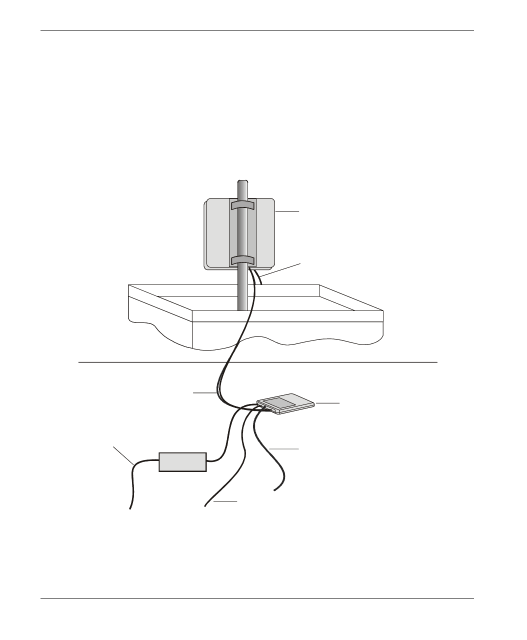
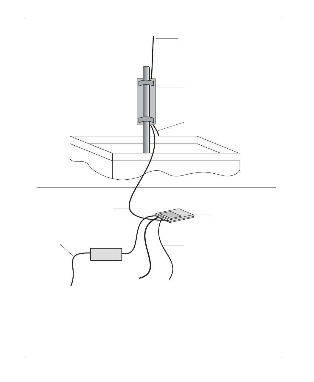
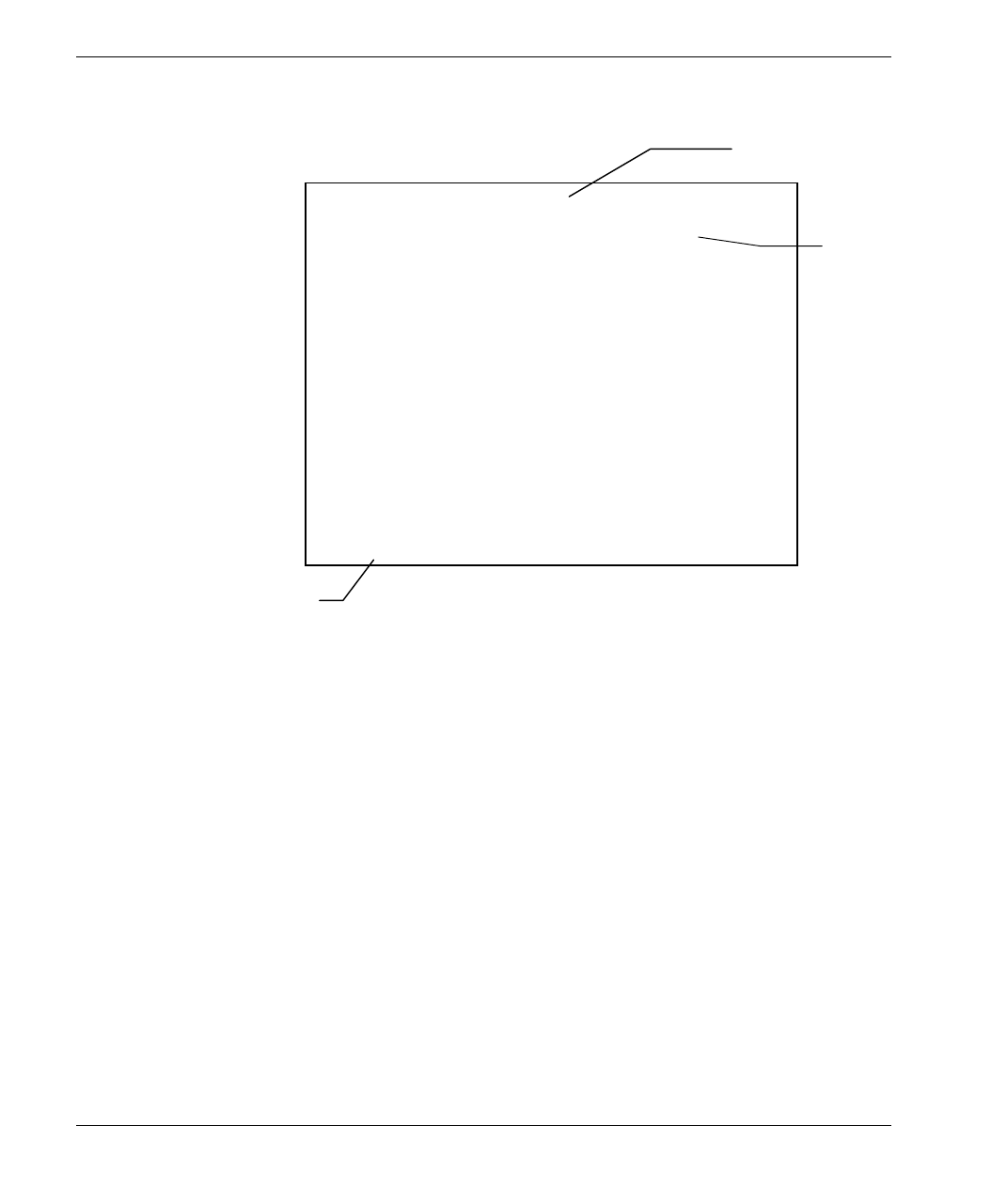
2.3 General Installation Scheme
Figure 2-1 depicts the general installation scheme for BreezeACCESS SU-A-2.4
Subscriber Units; Figure 2-2 depicts the general installation scheme for
BreezeACCESS SU-E-2.4 Subscriber Units.
IND OOR
UNIT
IF CABLE TO
OUTDOOR UNIT
TO MAINS
TO DATA
EQUIPMENT
GROUNDING
CABLE
OUTDOOR
UNIT
POWER
SUPPLY
INDOOR
UNIT
IF CABLE TO
OUTDOOR UNIT
TO MAINS
GROUNDING
CABLE
OUTDOOR
UNIT
TO TELEPHONE EQUIPMENT
(SU-A/E-DV SERIES ONLY)
POWER
SUPPLY
Figure 2-1: SU-A General Installation Scheme
Basic Installation
SU-A/E Subscriber Units Installation Manual 6 BreezeACCESS 2.4 Series
INDOOR
UNIT
IF CABLE TO
OUTDOOR UNIT
TO MAINS
TO DATA
EQUIPMENT
GROUNDING
CABLE
OUTDOOR
UNIT
POWER
SUPPLY
TO TELEPHONE EQUIPMENT
(SU-A/E-DV SERIES ONLY)
TO ANTENNA
Figure 2-2. SU-E General Installation Scheme

Basic Installation
BreezeACCESS 2.4 Series 7 SU-A/E Subscriber Units Installation Manual
2.4 Guidelines for Selection of Equipment Locations
Select appropriate locations for the Outdoor unit and for the Indoor unit using
the following guidelines.
SU-RA
• The SU-RA Outdoor unit should be mounted on a pole and should be
installed on a rooftop or a side-wall where a direct line of sight with the Base
Station antenna can be established. The higher the unit, the better the
achievable link quality.
• The antenna (integrated on the front side of the SU-RA Outdoor unit) should
be directed towards the Base Station. The unit should be installed in a way
that allows optimal alignment towards the Base Station. The location should
also be selected to allow easy access to the unit for installation and testing.
SU-RE
• The SU-RE outdoor unit should be installed as near as possible to its antenna.
• The antenna should be mounted on a pole and should be installed on a roof
top or side wall where a direct line of site with the Base Station can be
established. The higher the antenna, the better the achievable link quality.
• The antenna should be directed towards the Base Station. The antenna
should be installed in a way that allows optimum alignment towards the Base
Station. The location of the antenna should allow easy access for installation
and alignment.
SU-RA/RE
• The SU-RA/RE is connected to the SU-NI by means of an IF cable carrying
signaling, control signals and power. The IF frequency is 440 MHz. The
maximum allowed attenuation of the IF cable connecting the Outdoor unit to
the Indoor unit is 15dB and the maximum allowed DC resistance (the sum of
the DC resistance of the inner and outer conductors) is 1.5 ohm. This allows
for cable length of up to 30m when using the standard RG 58 cable.
If longer cables are required, a cable with lower attenuation and/or DC
resistance should be used. Table 2-1 provides details regarding some popular
cables such as the RG 58 and RG 213. If the spectral environment is polluted
with noise in the 440 MHz band, it is recommended to use a higher quality
Basic Installation
SU-A/E Subscriber Units Installation Manual 8 BreezeACCESS 2.4 Series
double-shielded cable such as the LMR 240 or LMR 400 (manufactured by
Times Communications).
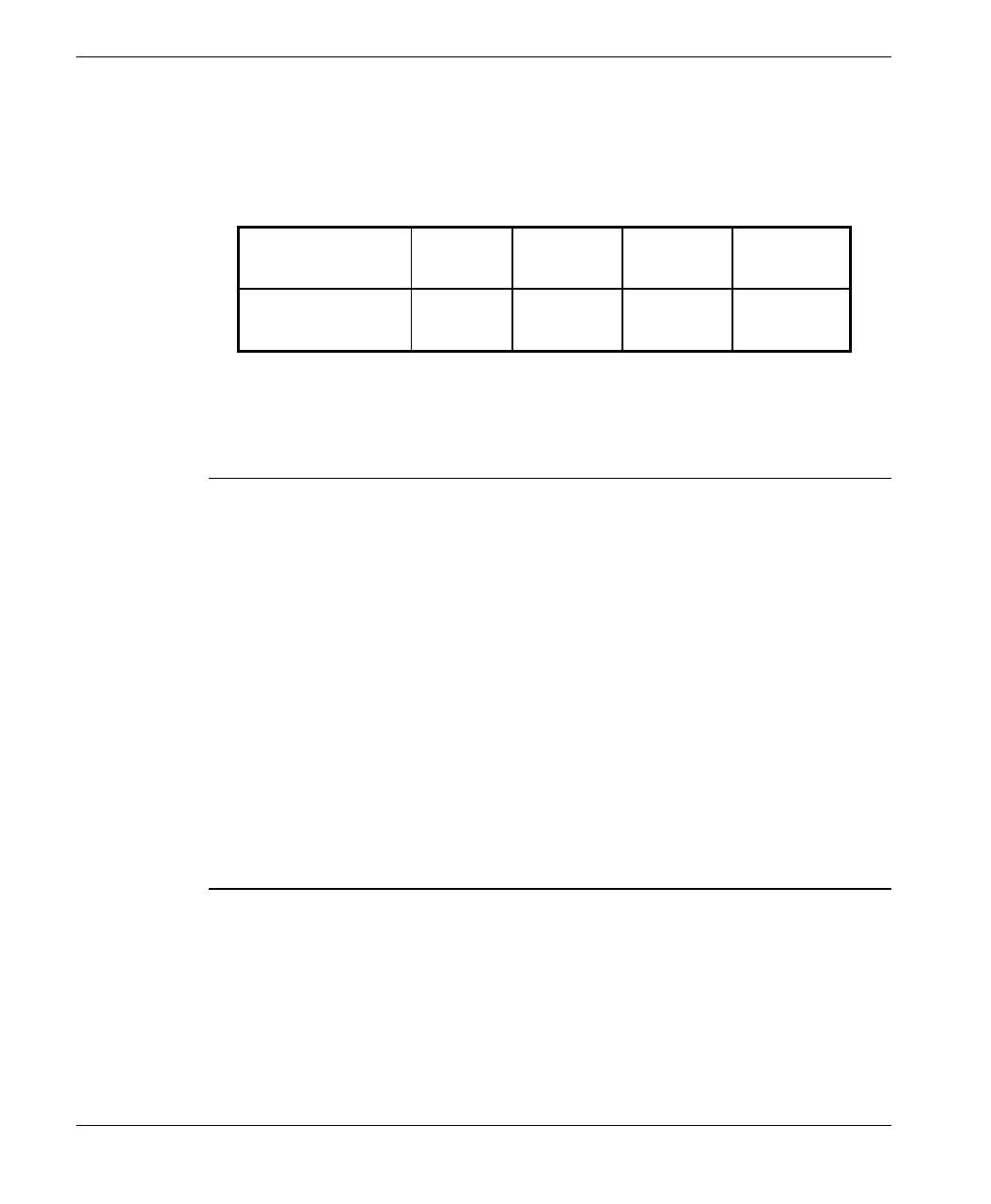
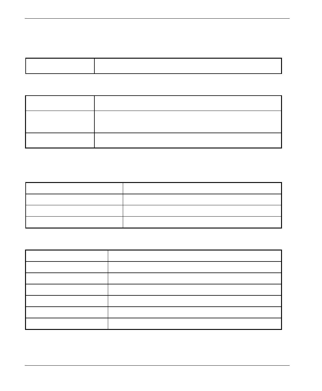
Table 2-1: IF Cables
Cable Type RG 58 RG 213 LMR 240 LMR 400
Maximum cable
Length (m) 30 100 65 150
• The Indoor unit should be installed in as close as possible to the building’s
entry point of the IF cable. The location of the Indoor unit should also take
into account the need to connect it to a power mains outlet and to the CPE.
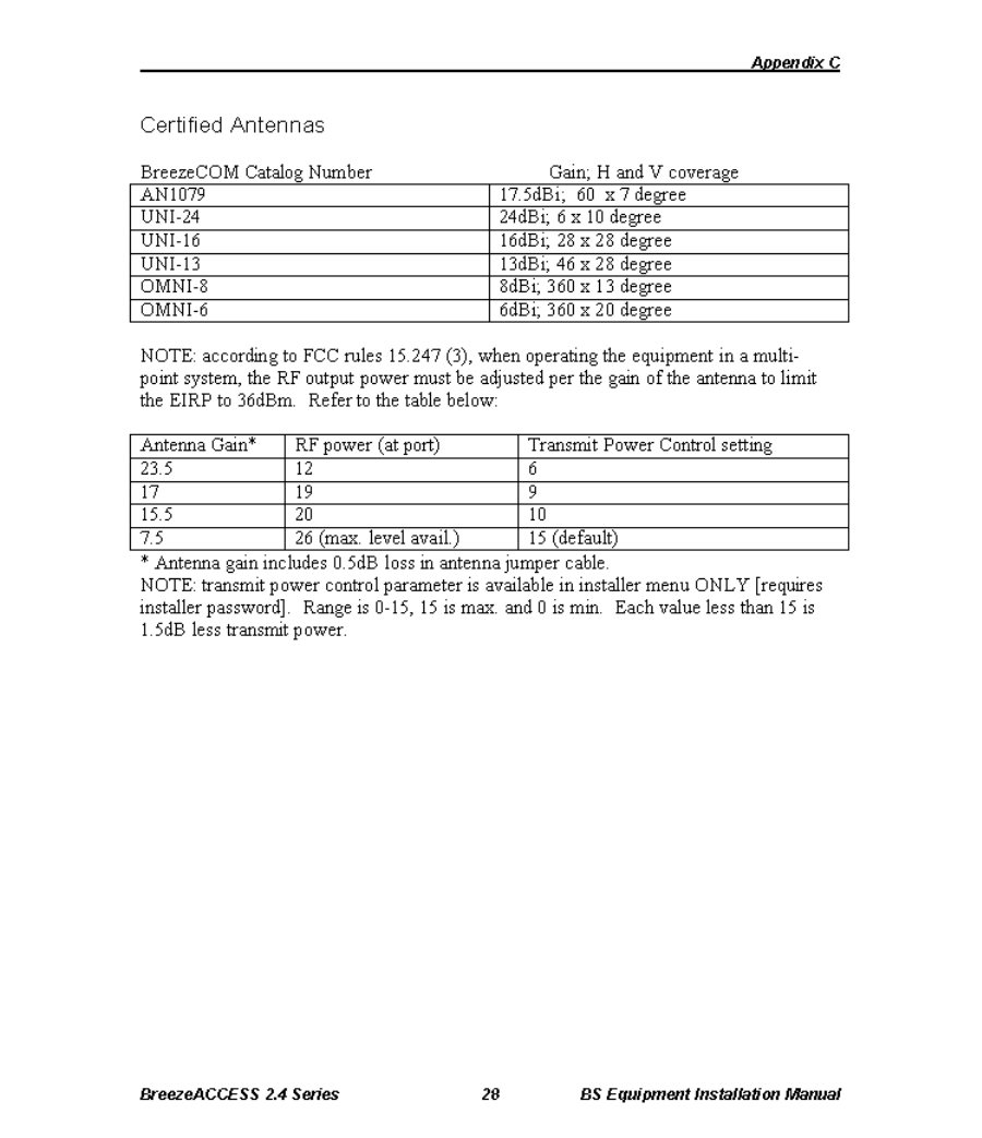
Notice: Outdoor units and antennas should be installed ONLY by experienced
installation professionals who are familiar with local building and safety
codes and, wherever applicable, are licensed by the appropriate government
regulatory authorities.
The system complies with the EN61000-4-5, level 3 (2kV) standard and is protected
against secondary lightning strikes when its outdoor unit is properly
grounded according to the applicable country-specific industry standards
for protection of structures against lightning. The use of any antenna other than
those certified with this product is forbidden in accordance to FCC rules 15.204.
Failure to do so may void the BreezeACCESS product warranty and may
expose the end user or the service provider to legal and financial liabilities.
BreezeCOM and its resellers or distributors are not liable for injury,
damage or violation of regulations associated with the installation of
outdoor units or antennas. Reffer to Appendix C for approved antennas.
Basic Installation
BreezeACCESS 2.4 Series 9 SU-A/E Subscriber Units Installation Manual
2.5 Installing the Outdoor Unit
2.5.1 Pole Mounting the Outdoor Unit
The Outdoor unit can be secured to the pole using one of the following options:
• Special brackets and open-ended screws (supplied with each unit). There
are two pairs of screw holes on the back of the unit, allowing use of the
special brackets with various pole widths.
• U-bolts – size A (inner installation holes, up to 2” pole).
• U-bolt – size B (outside installation holes, up to 3” pole).
• Metal bands (9/16” wide, minimum 12” long)
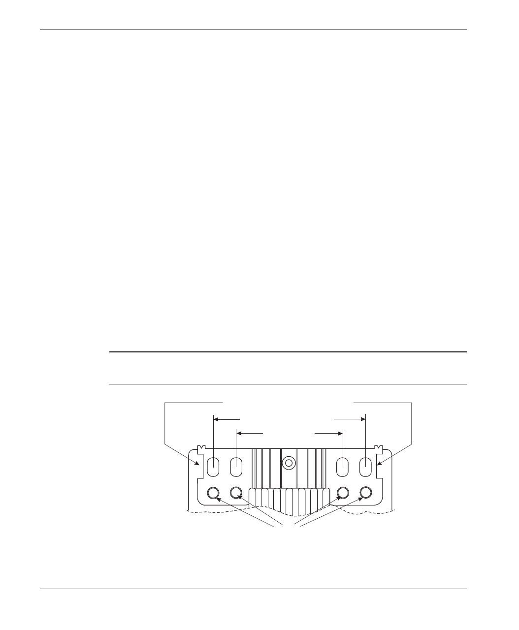
Figure 2-3 shows the locations of the u-bolt holes, band grooves and screw holes
on the rear side of the Outdoor unit.
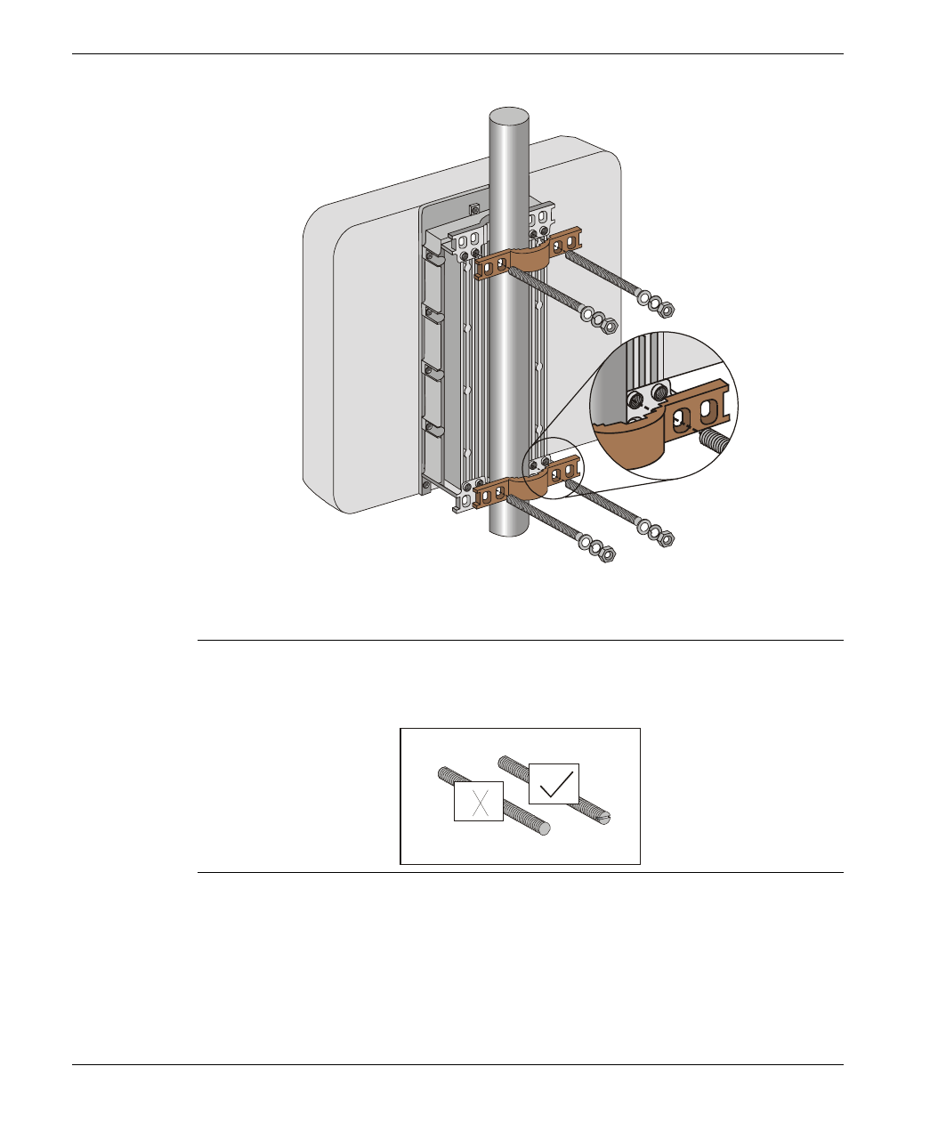
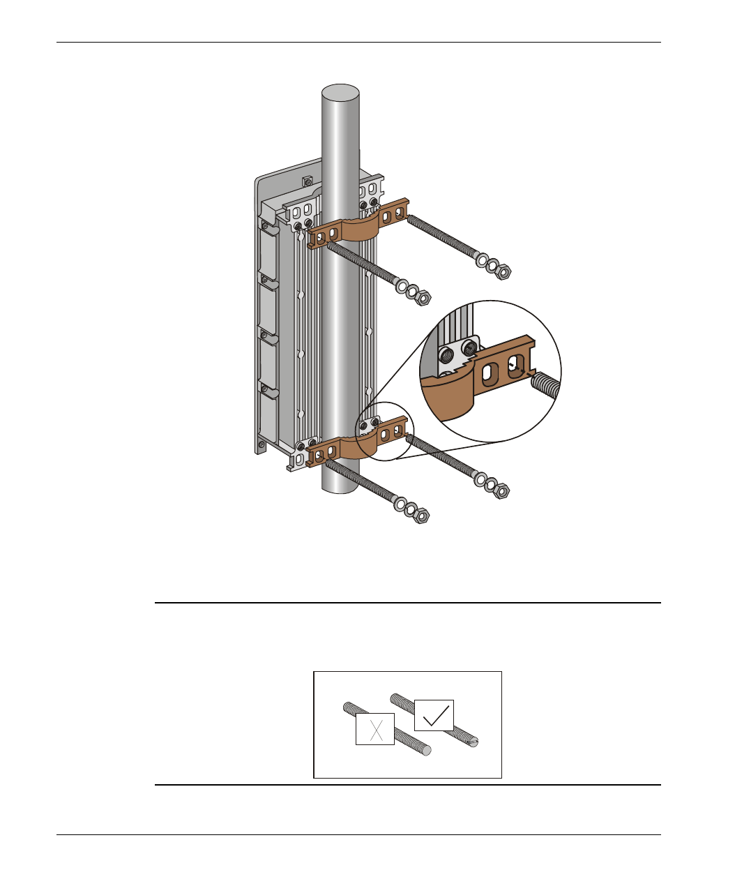
Figure 2-4 illustrates the method of installing an SU-RA Outdoor unit on a pole,
using the brackets and open-ended screws.
Figure 2-5 illustrates the method of installing an SU-RE Outdoor unit on a pole,
using the brackets and open-ended screws.
Note: Make sure to install the unit with the bottom panel (the panel with the IF
connector) facing downward.
Bracket Screw Holes
Grooves for Insertion of 9/16” Metal Band
Size B U-Bolt Holes (3” Pole)
Size A U-Bolt
Holes (2” Pole)
Figure 2-3. Holes/Grooves/Screw holes
Basic Installation
SU-A/E Subscriber Units Installation Manual 10 BreezeACCESS 2.4 Series
Figure 2-4. SU-RA 2” Pole Mounting Installation Using the Special Brackets
Note: When inserting the open-ended screws, make sure to insert them with the
grooves pointing outwards; these grooves are intended to allow fastening of
the screws with a screwdriver.
Basic Installation
BreezeACCESS 2.4 Series 11 SU-A/E Subscriber Units Installation Manual
Figure 2-5. SU-RE 3” Pole Mounting Installation Using the Special
Brackets
Note: When inserting the open-ended screws, make sure to insert them with the
grooves pointing outwards; these grooves are intended to allow fastening of
the screws with a screwdriver.
Basic Installation
SU-A/E Subscriber Units Installation Manual 12 BreezeACCESS 2.4 Series
2.5.2 Connecting the Antenna Cable (SU-RE)
Connect an RF cable between the ANT connector (located on the top panel of
the SU-RE unit) and the antenna.
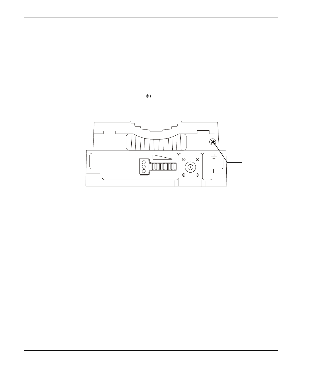
2.5.3 Connecting the Ground and IF Cables
The Ground terminal (marked and the IF cable connector (marked IF) are
located on the bottom panel of the SU-RA/RE Outdoor unit, shown in
Figure 2-6.
ETH
ALARM RSSI
IF
WLNK
Figure 2-6. SU-RA/RE Outdoor Unit Bottom Panel
1. Connect one end of the ground cable to the Ground terminal and connect the
other end to a good ground connection.
2. Connect the coaxial cable to the IF connector. Verify that the length of the
IF cable is sufficient and that it can easily reach the Indoor unit.
Note: Make sure to switch OFF the power of the SU-NI unit prior to
connecting/disconnecting the IF cable.
Ground
Screw
Basic Installation
BreezeACCESS 2.4 Series 13 SU-A/E Subscriber Units Installation Manual
2.6 Installing the SU-NI Indoor Unit
1. Place the SU-NI unit in an appropriate location on a shelf or a table. The unit
can be wall mounted using the installation materials provided with the unit.
Use a 6mm (1/4”) drill and the supplied template plate for easy and accurate
marking of the holes.
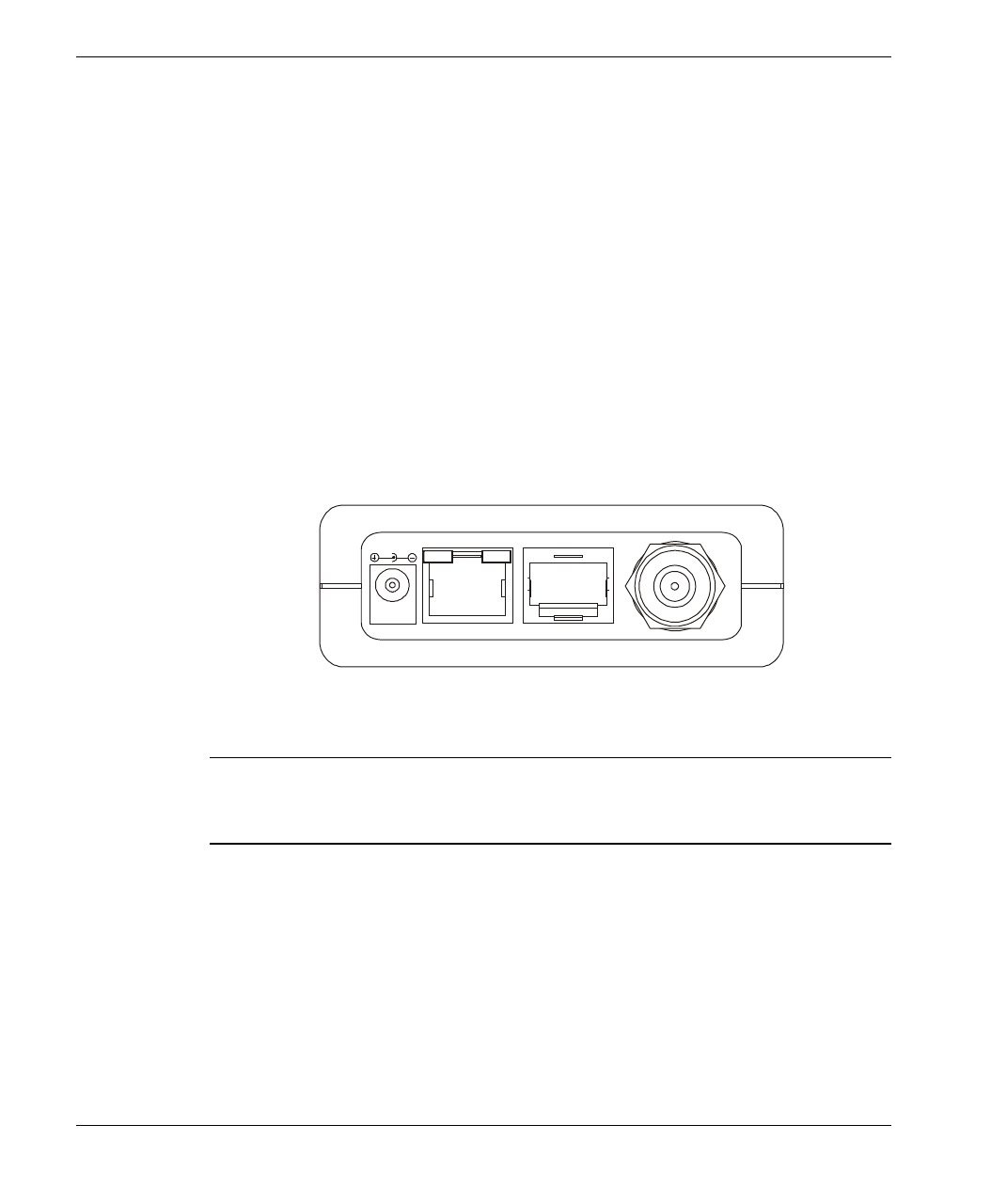
2. Connect the SU-PS DC power cord to the DC In jack (marked DC-12V)
located on the rear panel of the Indoor unit (shown in Figure 2-7).
3. Connect the IF cable to the IF connector (marked IF) on the rear panel of the
Indoor unit. The other side of the IF cable should already be connected to the
Outdoor unit.
4. Connect the mains power cord to the SU-PS. Connect the mains power plug
to a mains power outlet.
ETH
DC-12V
TEL
IF
Figure 2-7. SU-NI Rear Panel (unit with voice support)
Note: The rear panel pictured above in Figure 2-7 is of a SU-NI with voice
support; SU-NI units that belong to Subscriber Units without voice support
(SU-1D, SU-8D, SU-BD) are identical, except that they have no TEL port.
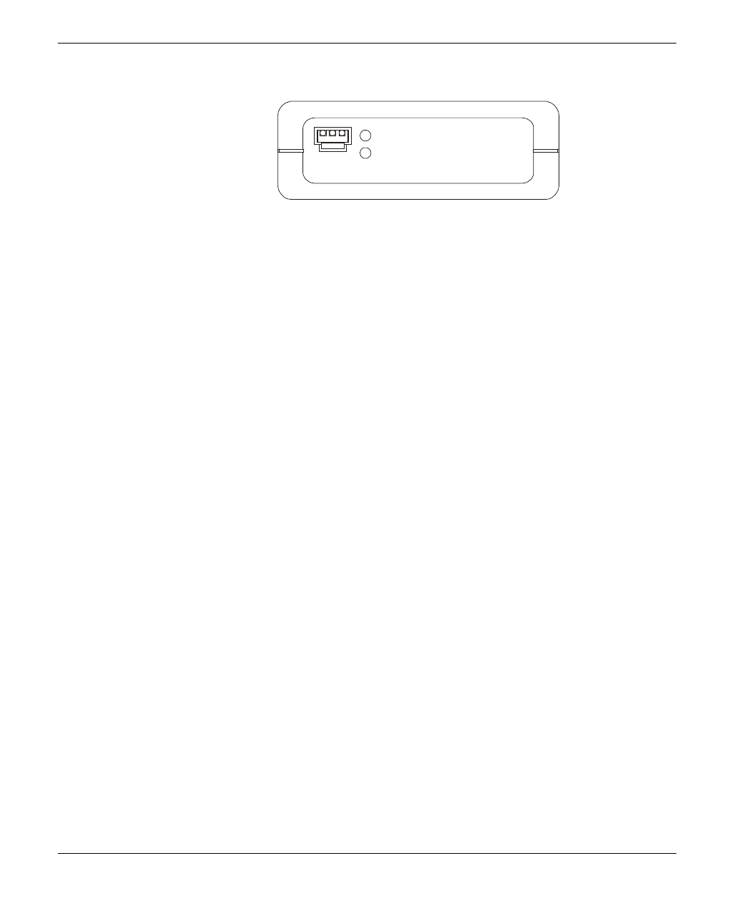
5. Verify that the Power LED (marked PWR) located on the front panel of the
Indoor Unit is turned ON.
Basic Installation
SU-A/E Subscriber Units Installation Manual 14 BreezeACCESS 2.4 Series
PWR
WLNK
MON
Figure 2-8. SU-NI Front Panel
6. Use a straight Ethernet 10baseT cable to connect a PC (SU-A/E -1D or SU-
A/E-1D1V), or a hub (all other units) to the Ethernet port (marked ETH)
located on the rear panel of the SU-NI unit.
7. For units that support voice connect the telephone cord to the telephone port
(marked TEL) located on the rear panel. Connect the other side of the cord
to the user’s telephone set.

Configuring System Parameters
BreezeACCESS 2.4 Series 15 SU-A/E Subscriber Units Installation Manual
3. CONFIGURING SYSTEM PARAMETERS
After completing the installation process, as described in the preceding section,
proceed with the configuration of the basic system parameters.
This section covers the configuration of basic installation parameters. Refer to the
Administration Manual for information related to other parameters.
Note: Optionally, the product can be configured using Telnet over the Ethernet
port, after setting IP address. For further information, see Appendix A.
3.1 Getting Started with the Local Terminal
1. Connect one end of the Monitor cable to the MON jack on the front panel of
the SU-NI Indoor unit. Connect the second end of the cable to the COM port
of the terminal. The COM port connector on the Monitor cable is a 9 pin
D-type plug.
2. Run a terminal emulation program (e.g., ProComm or Windows
HyperTerminal) using the following setup.
Baud rate 9600
Data bits 8
Stop bits 1
Parity None
Flow Control Xon/Xoff
Connector Available Com Port
3. Press
Enter. The Select Access Level menu appears. Select the access level
according to your authorized access level. You will be requested to enter
your password. After entering the correct password press enter. The main
menu appears (refer to Table 3-1).
Configuring System Parameters
SU-A/E Subscriber Units Installation Manual 16 BreezeACCESS 2.4 Series
Software
Version No.
BreezeACCESS/SU-1D
Official Release Version – 2.6.3
Release Date: Thu Aug 31 17:24:47 2000
Main Menu
=====================
1 – Info Screens
2 – Unit Control
3 – Basic Configuration
4 – Site Survey
5 – Advanced Configuration
BreezeACCESS >>>
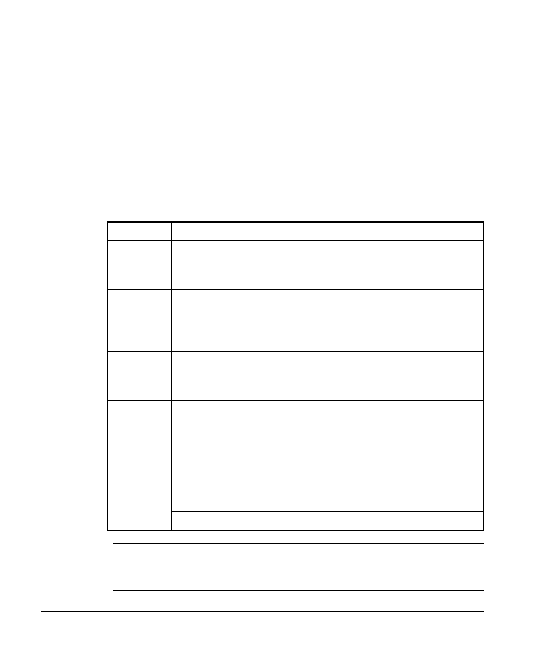
Table 3-1. Main Menu
The appearance of the displayed Main Menu varies in accordance with the
access level.
• For users with read only access rights, only the Info Screens option is
displayed. Users with this access level cannot access the Unit Control,
Basic Configuration, Site Survey and Advanced Configuration menus.
• For users with Installer access rights, the first four menu items (Info
Screens, Unit Control, Basic Configuration and Site Survey) are
displayed. Users with this access level cannot access the Advanced
Configuration menu.
• For users with Administrator access rights, the full Main Menu will be
displayed. These users can access all the menu items.
Unit Type
Unit Name

Configuring System Parameters
BreezeACCESS 2.4 Series 17 SU-A/E Subscriber Units Installation Manual
4. Operate the monitor program as follows:
• Type an option number to open/activate the option. You may need
to press the Enter key in some cases.
• Press the Esc key to exit a menu or an option.
• You can log-out and exit the monitor program at any time by
simultaneously pressing the Ctrl and X keys.
• Reset the unit after making configuration changes for the new
values to take effect.
• You can view the current parameters’ configuration by selecting 1
in the Main Menu to Access the Info Screens menu, and than
selecting 2 in the Info Screens menu to view the Basic
Configuration parameters.
3.2 Configuring Basic Parameters
The following system parameters must be configured for each specific installation:
• ESSID
• IP Address
• Subnet Mask
• Default Gateway Address
Note: You must select Reset Unit in the Unit Control menu for the changes to take
effect.
Subscriber Units should be configured after the applicable Access Unit is
operational. When configuring Subscriber Units, the first parameter that should
be configured is the ESSID. Otherwise the unit will not successfully synchronize
with the Access Unit and will continuously reset itself, thus interfering with the
configuration process.
See Appendix B for more details on the Basic Parameters.

Configuring System Parameters
SU-A/E Subscriber Units Installation Manual 18 BreezeACCESS 2.4 Series
1. From the main menu, type 3 to access the Basic Configuration menu.
2. From the Basic Configuration menu, type 4 to access the ESSID selection
screen. Enter the required ESSID.
3. Type 1 to access the IP Address selection screen. Enter the required IP
address.
4. Type 2 to access the Subnet Mask selection screen. Enter the required subnet
mask.
5. Type 3 to access the Default Gateway Address selection screen. Enter the
required default gateway address.
3.3 Reset Unit
1. From the main menu, type 2 to access the Unit Control menu.
2. Type 1 to access the Reset Unit menu. Type 1 to reset the unit so that new
configuration settings are applied.
Note: Should you make any mistakes during configuration or encounter any
problems associated with system configuration parameters, you may
configure the unit back to the factory defaults, as follows:
Type 2 in the Unit Control menu to access the Set Factory Defaults menu.
Type in 2 (Set Factory defaults-Full) to load the default values. Reset the
unit for the factory defaults values to take effect.

Aligning the Antenna
BreezeACCESS 2.4 Series 19 SU-A/E Subscriber Units Installation Manual
4. ALIGNING THE ANTENNA
Note: Antenna alignment using the RSSI bar display is possible only after the
Access Unit you wish to associate with is operational and the basic
parameters were properly configured (see Section 3.2). Otherwise the unit
will not be able to synchronize and associate with the Access Unit. As the
RSSI measurement is performed on received frames, its results are
meaningless as long as the unit is not associated with an AU.
1. Verify that the Power indication (the Yellow LED of the BSSI bar display)
is ON.
2. Align the antenna (integrated into the front side of the SU-RA Outdoor unit,
or separate if the unit is an SU-RE) to point towards the general direction of
the base station.
3. The RSSI bar display is located on the bottom panel of the Outdoor unit
(refer to Figure 2-6). The eight green RSSI LEDs are used for reading the
Received Signal Strength Indication. The higher the number of green LEDs
that are ON, the higher the level of the received signal. Rotate the antenna
left and/or right until you reach the point of maximum RSSI reading. Make
sure that at all times, the front of the antenna faces the general direction of
the base station.
4. For proper operation, at least one green LED should be ON. If you cannot
reach a point where at least one green LED is ON, try to improve the
reception quality by placing the antenna at a higher point or in a different
location.
Note: In some cases (e.g., when the Subscriber Unit is very close to the Base
Station), the antenna might have to be installed at an appropriate angle, in
order to ensure that it is directed towards the Base Station antenna).
5. Tighten the bracket screws (or the U-bolts/metal band), firmly securing the
unit or the antenna to the pole.
Verifying Correct Operation of the Outdoor Unit
SU-A/E Subscriber Units Installation Manual 20 BreezeACCESS 2.4 Series
5. VERIFYING CORRECT OPERATION OF THE
OUTDOOR UNIT
To verify correct operation, view the LED indicators located on the bottom panel
of the Outdoor unit as shown in Figure 2-6 on page 12.
The following table lists the various LED states.
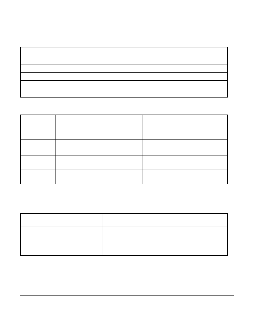
Table 5-1: SU-RA/RE Outdoor Unit LEDs
Name Description Functionality
ALARM Alarm
Indication On – A problem with the power amplifier or in
the locking process of any of the synthesizers
Off –Normal operation
WLNK Wireless link
activity Blinking –Receiving packet from the wireless
link
Off – No reception of packets from the wireless
link
ETH Ethernet
activity Blinking – Data received from or transmitted to
Ethernet LAN
Off – No activity on the Ethernet LAN
RSSI Bar display Displays the Received Signal Strength Indication.
The higher the number of green LEDs that are
ON, the higher the level of the received signal.
Yellow LED On - Power On
Off – Power is not received from the Indoor
unit
8 Green LEDs RSSI in 4 dB resolution starting at –91dBm
Red LED Received signal strength is –40dBm or higher
Note: Verifying proper operation of the Outdoor unit using the LEDs as described
above is possible only after completion of the configuration and alignment
processes.

RSSI Measurement and Maximum Data Rate Configuration
BreezeACCESS 2.4 Series 21 SU-A/E Subscriber Units Installation Manual
6. RSSI MEASUREMENT AND MAXIMUM DATA
RATE CONFIGURATION
6.1 Performing the RSSI Measurement
The Continuous Link Quality Display test allows a continuously updated display
of the average Received Signal Strength Indication. As the test measures only the
desired signal of properly received frames, it is a good indication to the quality
of the received signal.
Note: As the RSSI bar indicator is not accurate, it is recommended always to
perform the Continuous Link Quality Display test after the antenna was
optimally aligned.
1. Start the Monitor program as described in Section 3.1.
2. From the
Main Menu Type 4 to access the Site Survey menu.
3. Type 4 to activate the Continuous Link Quality Display selection screen.
4. On the screen you will get a continuously updated display of RSSI
measurements. To stop the test, press the Esc key.
RSSI Measurement and Maximum Data Rate Configuration
SU-A/E Subscriber Units Installation Manual 22 BreezeACCESS 2.4 Series
6.2 Configuring The Maximum Data Rate
1. If the measured average RSSI is less than 108 units, the default Maximum
Data Rate of 3 Mbps is to high and should be decreased.
2. From the Basic Configuration menu select 5 to access the Maximum Data
Rate selection menu.
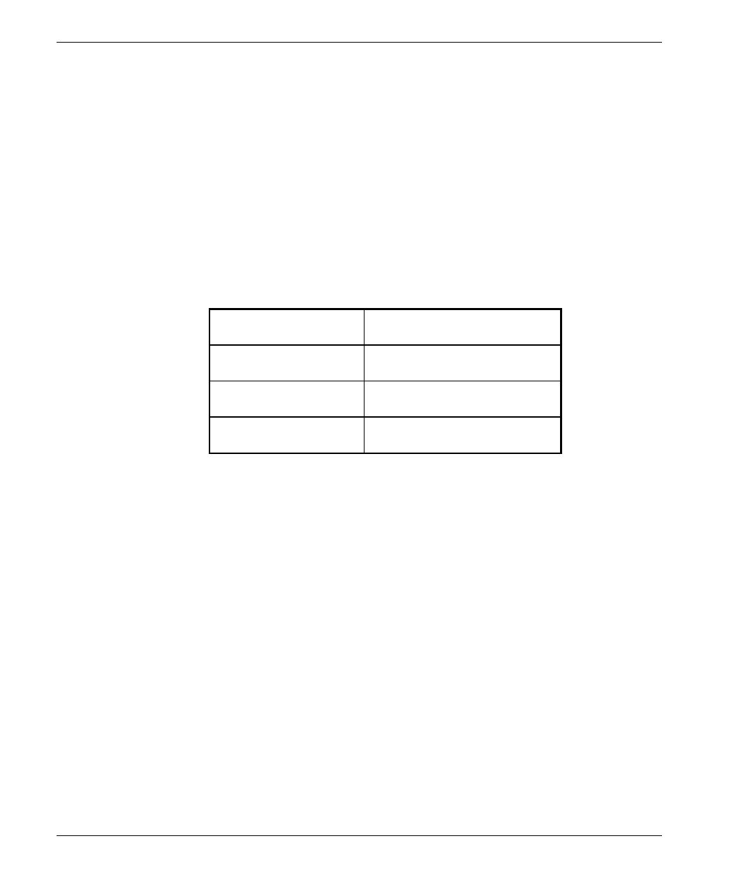
3. Configure the Maximum Data Rate according to Table 6-1.
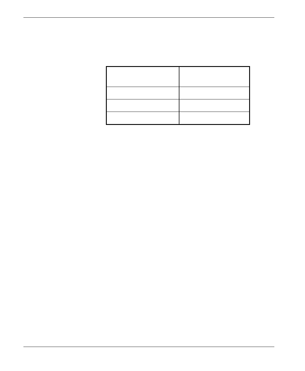
Table 6-1: RSSI vs. Maximum Data Rate
RSSI Maximum Data Rate
Higher than 108 3 Mbps
From 95 to 108 2 Mbps
Lower than 95* 1 Mbps
• If the RSSI is lower than 87 units the link quality is too
low and should be improved through installing the
antenna in a different and/or a higher location.
4. Reset the unit for the new configuration to become effective.
See Appendix B for more details on the Maximum Data Rate Parameter.
Verifying Correct Operation
BreezeACCESS 2.4 Series 23 SU-A/E Subscriber Units Installation Manual
7. VERIFYING CORRECT OPERATION
7.1 General
After completing the installation as described above, the system starts operation.
To verify correct operation, view the LED indicators located on the front panel
of the SU-NI Indoor unit as shown in Figure 2-8 on page 14.
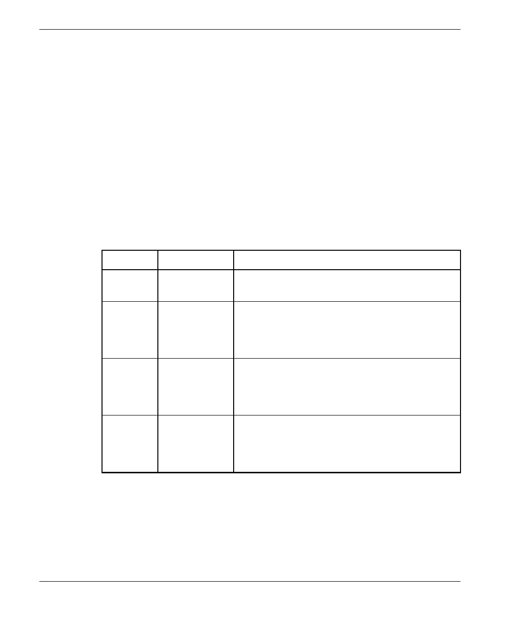
Table 7-1 lists the various LED states.
Table 7-1: SU-NI LEDs
Name Description Functionality
PWR Power supply On – After successful power up
Off – Power off
WLNK Wireless link
activity Blinking – Receiving packet from the wireless
link
Off – No reception of packets from the wireless
link
ETH
connector
embedded
LED
Ethernet
activity On – Receive/Transmit on Ethernet port
Off – No Receive/Transmit on Ethernet port
ETH
connector
embedded
LED
Ethernet
Integrity On – Unit is connected to Ethernet segment
Off – Unit is not connected to Ethernet segment
7.2 Verifying Data Connectivity
From the user’s PC or from a portable PC connected to the unit, Ping the unit or
try to connect it to the Internet.

Verifying Correct Operation
SU-A/E Subscriber Units Installation Manual 24 BreezeACCESS 2.4 Series
7.3 Verifying Telephone Connectivity (SU-A/E-DV series only)
To verify correct operation of the telephone, a test telephone with the default
telephony parameters and a known IP address should be connected to the system
(the location of the test telephone is determined by the system administrator).
Perform the following steps to verify telephone connectivity.
1. Use IP dialing to call the test telephone: dial * followed by the 12-digit IP
address of the test telephone. Verify connectivity. During the conversation,
verify that other party has your IP address.
2. After terminating the call, the other party should use the test telephone to
call your IP address and verify that the telephone, including the ringing
circuits, functions properly.
Specifications
BreezeACCESS 2.4 Series 25 SU-A/E Subscriber Units Installation Manual
8. SPECIFICATIONS
8.1 Radio
Frequency 2.4GHz ISM band
Radio Access Method FH-CDMA
Operation Mode Time Division Duplex
Channel Bandwidth 1 MHz
Antenna Gain (SU-RA) 17dBi, 20o
Output Power (at antenna port) 26 dBm (HP) or 2 dBm (LP) typical.
Power Control range: 20 dB
Sensitivity
(dBm at antenna port, BER 1E10-6)
1Mbps
2Mbps
3Mbps
-87
-81
-73
Data Rate 3Mbps max
Modulation Multilevel GFSK
Specifications
SU-A/E Subscriber Units Installation Manual 26 BreezeACCESS 2.4 Series
8.2 Data Communication
Standard Compliance IEEE 802.3 CSMA/CD
8.3 Voice Communication (SU-A/E-DV series)
Protocol H.323 Voice over IP compliant
Compression G.723 6.3 Kbps compression, G.729 8 Kbps compression,
G.711 64 Kbps transparent
Echo Cancellation G.168, G.131
8.4 Outdoor Unit to Indoor Unit Communication
IF Frequency 440 MHz
IF cable Impedance 50 ohm
Maximum IF cable Attenuation 15dB
Maximum IF cable DC Resistance 1.5 ohm
8.5 Configuration and Management
Local Management Via MON port, Monitor program using terminal emulation
Remote Management SNMP, Telnet, TFTP
Remote Management Access From Wired LAN, Wireless Link
SNMP Agents MIB II, Bridge MIB, Private MIBs
Accounting RADIUS compatible client
Security Authentication and filtering
Software upgrade TFTP download
Specifications
BreezeACCESS 2.4 Series 27 SU-A/E Subscriber Units Installation Manual
8.6 Interfaces
Interface Outdoor unit SU-NI indoor unit
IF TNC jack, lightning protected TNC jack, lightning protected
RF (SU-E) N-Type jack , lightning protected
Ethernet 10Base-T (RJ-45) with 2 embedded LEDs
Monitor 3-pin low profile
Power 12 VDC via the IF cable DC Plug for the SU-PS power supply
8.7 Electrical, Mechanical and Environmental
Outdoor Unit SU-NI Indoor Unit
Power 12 VDC from SU-NI via the IF cable SU-NI: 12VDC/2.5A from SU-PS
SU-PS: 100 – 240 VAC, 47-63 Hz
Mechanical SU-RA: 30cm x 30cm x 7.2 cm, 3 kg
SU-RE: 30cm x 12cm x 5 cm, 2.2 kg.
SU-NI: 13cm x 8.6cm x 3cm, 0.5 kg.
SU-PS: 10cm x 6.5cm x 3.5cm, 0.4 kg.
Operating
Temperature -400C to 600C0
0
C to 400C
Operating
Humidity 5%-95% non condensing,
Weather protected 5%-95% non condensing
8.8 Standards Compliance, General
EMC FCC part 15, EN 300 826
Safety UL 1950, EN 60950
Environmental GR - 63 - CORE (Bellcore), ETS 300 019
Surge Immunity EN 61000-4-5, test level 3 (2kV)

Appendix B
SU-A/E Subscriber Units Installation Manual 28 BreezeACCESS 2.4 Series
APPENDIX A. USING TELNET
Use the following procedure to connect to BreezeACCESS units via a Telnet
session.
1. Connect the PC to the Ethernet port of the unit (or the hub to which the unit
is connected) using a straight Ethernet cable. If you connect the PC directly
to a unit that is normally connected to a hub, use a crossed Ethernet cable.
You may also connect the PC to any Ethernet port on the network and
communicate with the unit to be managed via the wired or wireless media.
2. Make sure that the IP parameters of the PC are configured to enable
connectivity with the unit.
3. Run a Telnet application and use the IP address of the unit to be managed as
the Host Name.
4. Set Port to Telnet (this is the default).
5. Set Terminal Type to VT100 (this is the default).
6. Enter the Service Provider password.
7. When the password is recognized, the following message is displayed:
You have entered.
8. Press Enter, the Breeze ACCESS Monitor is displayed on the screen.
To exit the Telnet session, choose Disconnect from the Connect menu.
(The session is terminated automatically, after a specific time of inactivity
determined by the Log-out Timer).

Appendix B
BreezeACCESS 2.4 Series 29 SU-A/E Subscriber Units Installation Manual
APPENDIX B. BASIC PARAMETERS
• IP Address – Displays the current IP address of the unit and allows entry
of a new IP address (4 x 3 digit octets, separated by dots). The default IP
Address is 010.000.000.001.
• Subnet Mask – Displays the current subnet mask of the unit and allows
entry of a new subnet mask (4 x 3 digit octets, separated by dots). The
default mask is 255.000.000.000.
• Default Gateway Address – Displays the current address of the default
gateway of the unit and allows entry of a new default gateway address (4 x
3 digit octets, separated by dots). The default gateway address is
000.000.000.000.
• ESS ID – The ESSID (Extended Service Set ID) of the unit (up to 32 printable
ASCII characters). The ESSID is a string used to identify a wireless network. It
prevents the unintentional merging of two co-located wireless networks. An
SU can only associate with an AU that has an identical ESSID. Use different
ESSIDs to segment the wireless access network and add security to your
network. The default value is ESSID1.
Note: The ESSID string is case-sensitive.
• Maximum Data Rate – Displays the current maximum data rate, and
allows entry of a new value for the maximum data rate. BreezeACCESS
units operate at 1 Mbps, 2 Mbps or 3 Mbps. Under certain conditions
(compatibility reasons or range/speed trade-off), you may decide to limit
the use of higher rates. If the quality of the link is not good enough, it is
recommended to decrease the value of this parameters (the higher the date
rate, the higher the error rate). The link quality can be estimated based on
the RSSI measurement at the SU, assuming that the RF link budgets are the
same for both directions. Otherwise, there is a high probability that the unit
will have to retransmit many frames several times before temporarily
reducing the data rate.
A high number of retransmissions reduces the overall throughput for the
selected SU as well as for all the other SUs served by the same AU. If the
Appendix B
SU-A/E Subscriber Units Installation Manual 30 BreezeACCESS 2.4 Series
measured RSSI is less than a certain threshold, it is recommended to
decrease the Maximum Data Rate in accordance with the following table:
RSSI
(SU-A/E-2.4) Recommended
Maximum Data Rate
RSSI > 108 3Mbps
95 > RSSI > 108 2Mbps
RSSI < 95 1Mbps
The default value is 3 Mbps. Allowed values are 1, 2 or 3 Mbps.