Alvarion Technologies IF-24 WLAN User Manual Updated
Alvarion Ltd. WLAN Updated
Contents
- 1. Base Station Manual
- 2. Subscriber Unit Manual
- 3. Updated user manual
Updated user manual
BreezeACCESS
Base Station Equipment
Installation
Manual
February, 2001
Cat. No. 213155

Front Matter
Base Station Equipment Installation Manual ii BreezeACCESS Series
© 2001 by BreezeCOM Ltd. All rights reserved.
No part of this publication may be reproduced in any material form without the written permission of the
copyright owner.
Trade Names
BreezeACCESS, BreezeNET, BreezeLINK, BreezeVIEW and BreezeMANAGE are trade names of
BreezeCOM Ltd. Other brand and product names are registered trademarks or trademarks of their
respective companies.
Statement of Conditions
The information contained in this manual is subject to change without notice. BreezeCOM shall not be
liable for errors contained herein or for incidental or consequential damages in connection with the
furnishing, performance, or use of this manual or equipment supplied with it.
Warranty
In the following warranty text, “the Company” shall mean:
• BreezeCOM Ltd., for products located outside the USA.
• BreezeCOM Inc., for products located in the USA.
This BreezeACCESS product is warranted against defects in material and workmanship for a period of
one year from date of purchase. During this warranty period the Company will, at its option, either
repair or replace products that prove to be defective.
For warranty service or repair, the product must be returned to a service facility designated by the
Company. Authorization to return products must be obtained prior to shipment. The buyer shall pay all
shipping charges to the Company and the Company shall pay shipping charges to return the product to the
buyer.
The Company warrants that the firmware designed by it for use with the unit will execute its
programming instructions when properly installed on the unit. The Company does not warrant that the
operation of the unit or firmware will be uninterrupted or error-free.

Front Matter
BreezeACCESS Series iii Base Station Equipment Installation Manual
Limitations of Warranty
The foregoing warranty shall not apply to defects resulting from improper or inadequate maintenance by
the buyer, buyer supplied interfacing, unauthorized modification or misuse, operation outside of the
environmental specifications for the product, or improper site preparation or maintenance. No other
warranty is expressed or implied. The Company specifically disclaims the implied warranties of
merchantability and fitness for any particular purpose.
BreezeCOM shall not be liable to any person for any special or indirect damages, including, but not
limited to, loss of profits or revenues, loss of use or damage to any associated equipment, cost of
capital, cost of substitute products, facilities or services, downtime costs or claims resulting from any
cause whatsoever arising from or in any way connected with the manufacture, sale, handling, service,
repair, maintenance or use of the products. In no event shall the company’s liability exceed the purchase
price denoted on the invoice.
Electronic Emission Notice
This device complies with Part 15 of the FCC rules. Operation is subject to the following two
conditions:
1. This device may not cause harmful interference.
2. This device must accept any interference received, including interference that may cause undesired
operation.
FCC Radio Frequency Interference Statement
This equipment has been tested and found to comply with the limits for a class B digital device, pursuant
to Part 15 of the FCC rules. These limits are designed to provide reasonable protection against harmful
interference when the equipment is operated in a residential environment notwithstanding use in
commercial, business and industrial environments. This equipment generates, uses, and can radiate radio
frequency energy and, if not installed and used in accordance with the instruction manual, may cause
harmful interference to radio communications.
FCC Radiation Hazard Warning
To comply with FCC RF exposure requirements in section 1.1307, a minimum separation distance as
defined in the following table is required between the antenna and all persons:
Product Minimum Distance
BreezeACCESS MMDS, SU-A/E 64 cm (26 inches)
BreezeACCESS II, SU-A/E 2 m (79 inches)

Front Matter
Base Station Equipment Installation Manual iv BreezeACCESS Series
R&TTE Compliance Statement
This equipment complies with the appropriate essential requirements of Article 3 of the R&TTE
Directive 1999/5/EC.
Information to User
Any changes or modifications of equipment not expressly approved by the manufacturer could void the
user’s authority to operate the equipment.
Safety Considerations
For the following safety considerations, “Instrument” means the BreezeACCESS Base Station equipment
components and cables.
Caution
To avoid shock, do not perform any servicing unless you are qualified to do so.
Line Voltage
Before connecting this instrument to the power line, make sure that the voltage of the power source
matches the requirements of the instrument.
Radio
The instrument transmits radio energy during normal operation. To avoid possible harmful exposure to
this energy, do not stand or work for extended periods of time in front of its antenna. The long-term
characteristics or the possible physiological effects of Radio Frequency Electromagnetic fields have not
been yet fully investigated.
Antenna Installation and Grounding
Be sure that the Outdoor unit, the antenna and the supporting structure are properly installed to eliminate
any physical hazard to either people or property. Verify that the antenna mast is grounded so as to
provide protection against voltage surges and static charges. Make sure that the installation of the
outdoor unit, antenna and cables is performed in accordance with all relevant national and local building
and safety codes.

Table of Contents
BreezeACCESS Series v Base Station Equipment Installation Manual
Table of Contents
1. INTRODUCTION............................................................................................................1
2. BASIC INSTALLATION.................................................................................................3
2.1 Packing List – Modular Shelf Equipment........................................................................3
2.1.1 BS-SH Base Station Shelf.......................................................................................3
2.1.2 AU-A/E-BS Access Units (up to six per shelf).........................................................3
2.1.3 BS-PS Power Supply (one or two per shelf).............................................................3
2.2 Packing List – Stand-alone AU-A/E-NI Access Unit.......................................................4
2.3 Other Items Required for Installation..............................................................................4
2.4 Guidelines for Selection of Equipment Location.............................................................4
2.5 Installing the Outdoor Radio Unit...................................................................................7
2.5.1 Mounting the Outdoor Unit.....................................................................................7
2.5.2 Connecting the Antenna Cable (AU-RE)..................................................................9
2.5.3 Connecting the Ground and IF Cables .....................................................................9
2.6 Installing the Modular Shelf Indoor Equipment..............................................................11
2.6.1 BS-SH Slot Assignments......................................................................................11
2.6.2 The BS-AU.........................................................................................................12
2.6.3 The BS-PS..........................................................................................................14
2.6.4 Shelf and Modules Installation Procedure..............................................................15
2.7 Installing the AU-NI Indoor Unit..................................................................................16
3. CONFIGURING SYSTEM PARAMETERS..................................................................17
3.1 Getting Started with the Local Terminal.......................................................................17
3.2 Configuring Basic Parameters......................................................................................19
3.2.1 Configuring Parameters Common to All Product Families....................................... 21
3.2.2 Configuring Parameters Specific to BreezeACCESS II........................................... 21
3.2.3 Configuring Parameters Specific to BreezeACCESS XL.........................................22
3.2.4 Configuring Parameters Specific to BreezeACCESS MMDS ..................................23
3.3 Reset Unit..................................................................................................................23

Table of Contents
Base Station Equipment Installation Manual vi BreezeACCESS Series
4. VERIFYING CORRECT OPERATION........................................................................24
4.1 Verifying Correct Operation of the AU-A/E-BS............................................................ 24
4.2 Verifying Correct Operation of the AU-A/E-NI.............................................................24
4.3 Verifying Correct Operation of the Outdoor Unit ..........................................................25
5. SPECIFICATIONS........................................................................................................26
5.1 Radio ........................................................................................................................ 26
5.1.1 BreezeACCESS II................................................................................................26
5.1.2 BreezeACCESS XL.............................................................................................27
5.1.3 BreezeACCESS MMDS.......................................................................................28
5.2 Outdoor Unit to Indoor Unit Communication ................................................................28
5.3 Configuration and Management ...................................................................................28
5.4 Interfaces................................................................................................................... 29
5.5 Electrical................................................................................................................... 29
5.6 Mechanical................................................................................................................29
5.7 Environmental............................................................................................................30
5.8 Standards Compliance, General...................................................................................30
APPENDIX A. USING TELNET.......................................................................................31
APPENDIX B. BASIC PARAMETERS.............................................................................33
APPENDIX C. MMDS CHANNELS AND FREQUENCIES.............................................45
APPENDIX D. FCC-CERTIFIED ANTENNAS FOR BREEZEACCESS II.....................47

Table of Figures
BreezeACCESS Series vii Base Station Equipment Installation Manual
Table of Figures
Figure 2-1. Holes/Grooves/Screw Holes ............................................................................7
Figure 2-2. AU-RE 3" Pole Mounting Installation Using the Special Brackets......................8
Figure 2-3. BreezeACCESS II and BreezeACCESS MMDS AU-RA/AU-RE Radio Unit
Bottom Panel ....................................................................................................................9
Figure 2-4. BreezeACCESS XL AU-RE Radio Unit Bottom Panel.......................................9
Figure 2-5. Shelf Slot Assignments..................................................................................11
Figure 2-6. BS-AU Front Panel........................................................................................12
Figure 2-7. BS-PS Front Panel......................................................................................... 14
Figure 2-8. AU -NI Rear Panel........................................................................................16
Figure 2-9. AU -NI Front Panel.......................................................................................16
Figure 3-1. Main Menu...................................................................................................18
Table of Tables
Table 2-1. IF Cables.........................................................................................................5
Table 2-2: BS-AU LEDs.................................................................................................13
Table 2-3. BS-PS Power Supply LEDs ............................................................................14
Table 4-1. AU-NI LEDs .................................................................................................24
Table 4-2. AU-RA/RE LEDs...........................................................................................25
Table 5-3. Hopping Sequences........................................................................................35

Introduction
BreezeACCESS Series 1 Base Station Equipment Installation Manual
1. INTRODUCTION
This manual describes installation guidelines for BreezeACCESS base station
equipment, including the stand-alone AU-E/A-NI-Access Units and the modular
AU-E/A-BS-Units with the BS-SH rack mounted shelf.
The BreezeACCESS Broadband Wireless Access system allows access service
providers to provide high-speed IP connectivity services to their subscribers. To
support IP-based services effectively BreezeACCESS systems employ wireless
packet data switching technology.
The AU-A/E-NI and the AU-A/E-BS Access Units are comprised of an indoor
unit and an outdoor unit. In the AU-A-NI and AU-A-BS products, the outdoor unit
(AU-RA) contains the radio module and an integral flat antenna. In the AU-E-NI
and AU-E-BS products, the outdoor unit (AU-RE) contains the radio module and
an interface to an external antenna (not included).
The indoor unit of the AU-A/E-NI is a stand-alone unit (AU-NI) that is powered
from the mains via its AU-PS power supply unit. The indoor unit of the AU-A/E-
BS is a module (BS-AU) that is designed for insertion into the BS-SH shelf. The
BS-SH, which is a 3U shelf suitable for installation in 19" racks, can contain up to
six BS-AU active modules and one or two BS-PS power supply modules. The
shelf is powered from a –48VDC power source. Power supply redundancy is
supported through the optional use of a second BS-PS power supply module.
The indoor unit provides the interface to the network. It also contains an IF
(Intermediate Frequency) module and is connected to the outdoor unit via a
50-ohm coaxial IF cable. The IF cable serves for transmission of the 440MHz IF
signal between the indoor and the outdoor units. It also serves for transferring
power (12VDC), management and control signals from the indoor unit to the
outdoor unit.
Introduction
Base Station Equipment Installation Manual 2 BreezeACCESS Series
BreezeACCESS products use Frequency Hopping Spread Spectrum radios and
are available in the following frequency bands:
• BreezeACCESS II products operate in Time Division Duplex (TDD)
mode in the 2.4-2.5GHz frequency band. The exact frequencies vary in
accordance with specific country’s radio regulations. BreezeACCESS II
products are available with an output power at the antenna port of either
26dBm (HP), 15dBm (GP), 7dBm (MP) or 2dBm (LP).
• BreezeACCESS MMDS products operate on Time Division Duplex
(TDD) mode in the 2.500-2.686GHz frequency band.
• BreezeACCESS XL products operate in Frequency Division Duplex
(FDD) mode, and are currently available in the following frequency bands:
Model Uplink Band (GHz) Uplink-Downlink
Separation (MHz)
BreezeACCESS 3.5a 3.410-3.452 100
BreezeACCESS 3.5a1 3.400-3.450 100
BreezeACCESS 3.5b 3.450-3.500 100
BreezeACCESS 3.5e 3.425-3.450 50
BreezeACCESS 2.6b 2.551-2.593 74
BreezeACCESS 3.3 3.300-3.324 76
BreezeACCESS 3.8 3.925-4.015 -320
Note: The information contained in this manual is applicable to
BreezeACCESS units with software release 3.0 and up.

Basic Installation
BreezeACCESS Series 3 Base Station Equipment Installation Manual
2. BASIC INSTALLATION
2.1 Packing List – Modular Shelf Equipment
2.1.1 BS-SH Base Station Shelf
• BS-SH shelf (with blank panels)
• Rubber legs for optional desktop installation
Note: Unless ordered otherwise, each BS-SH will be shipped with one BS-PS
power supply installed.
2.1.2 AU-A/E-BS Access Units (up to six per shelf)
• Outdoor unit:
⇒ AU-RA with integral antenna
OR
⇒ AU-RE with a connector to an external antenna (not included)
• Pole mounting kit for the outdoor unit (with two brackets, four sets of
screws, nuts and washers)
• BS-AU Network Interface module
• Monitor cable
2.1.3 BS-PS Power Supply (one or two per shelf)
• BS-PS Power Supply module
• Power cable

Basic Installation
Base Station Equipment Installation Manual 4 BreezeACCESS Series
2.2 Packing List – Stand-alone AU-A/E-NI Access Unit
• AU-NI indoor unit
• Outdoor unit:
⇒ AU-RA with integral antenna
OR
⇒ AU-RE with a connector to an external antenna (not included)
• AU-PS power supply with a mains power cord
• Pole mounting kit for the Outdoor unit (with two brackets, four sets of
screws, nuts and washers)
• Wall mounting kit for the AU-NI unit
2.3 Other Items Required for Installation
• IF cable (s)* (one for each AU)
• Grounding cable(s) with an appropriate termination (one for each AU)
• Ethernet cable(s) (straight, one for each AU)
• Antenna(s)* and RF cable(s)* (AU-E-NI or AU-E-BS only)
• A portable PC with terminal emulation software
• Installation tools and materials.
Items marked with an asterisk (*) are available as options from BreezeCOM.
2.4 Guidelines for Selection of Equipment Location
Select appropriate locations for the equipment using the following guidelines:
• The outdoor unit can be pole—or wall mounted. Its location should allow
easy access to the unit for installation and testing.
• The AU-RA unit with its integrated antenna, or the external antenna connected
to the AU-RE unit, should be installed where it provides coverage of all
subscriber units in the area it is intended to serve. The higher the AU-RA or
the antenna, the better coverage it can provide.

Basic Installation
BreezeACCESS Series 5 Base Station Equipment Installation Manual
• The AU-RE outdoor unit should be installed as near as possible to its
antenna.
Note: The distance between any two antennas should be greater than 40 cm.
• The outdoor unit is connected to the indoor unit by means of a coaxial IF
cable carrying signals, controls and power. The IF frequency is 440 MHz.
The maximum allowed attenuation of the IF cable is 15dB and its maximum
allowed DC resistance (the sum of the DC resistance of the inner and outer
conductors) is 1.5 ohm. This allows for cable lengths of up to 30m when
using the standard RG 58 cable. If longer cables are required, a cable with
lower attenuation and/or DC resistance should be used.
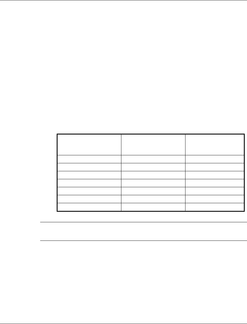
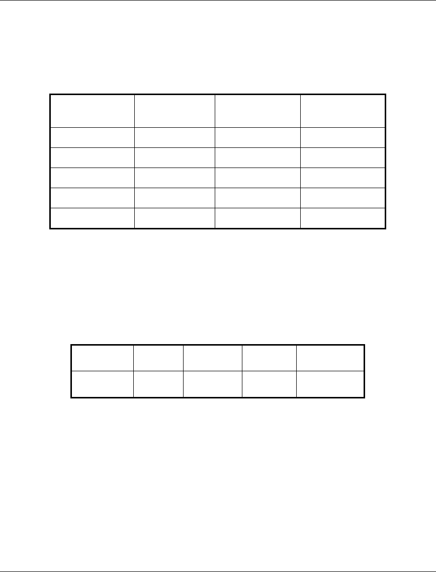
Table 2-1 provides data regarding several industry-standard cables such as
RG 58 and RG 213. If the spectral environment is polluted with noise in the
440 MHz band, it is recommended to use a higher quality double-shielded
cable such as LMR 240 or LMR 400 (manufactured by Times
Communications).
Table 2-1. IF Cables
Cable Type
RG 58
RG 213
LMR 240
LMR 400
Maximum cable
Length (m)
30
100
65
150
• The BS-SH and its modules and the SU-NI are designed for indoor operation,
i.e., inside buildings, a suitable cabinet or a shelter. Air temperature control
might be necessary – the equipment is designed to operate over the
temperature range 0°C to 45°C.

Basic Installation
Base Station Equipment Installation Manual 6 BreezeACCESS Series
Note: Outdoor units and antennas should be installed ONLY by experienced
installation professionals who are familiar with local building and safety
codes and, wherever applicable, are licensed by the appropriate
government regulatory authorities.
The system complies with the ETS 300 385 standard and is protected
against secondary lightning strikes when its outdoor unit is properly
grounded according to the applicable country-specific industry standards
for protection of structures against lightning. The system complies with
EN 61000-4-5, test level 3 (2kV).
Failure to do so may void the BreezeACCESS product warranty and may
expose the end user or the service provider to legal and financial liabilities.
BreezeCOM and its resellers or distributors are not liable for injury,
damage or violation of regulations associated with the installation of
outdoor units or antennas.
Basic Installation
BreezeACCESS Series 7 Base Station Equipment Installation Manual
2.5 Installing the Outdoor Radio Unit
2.5.1 Mounting the Outdoor Unit
The outdoor unit can be secured to the pole using one of the following options:
• Special brackets and open-ended screws (supplied with each unit). There
are two pairs of screw holes on the rear of the unit, allowing use of the
brackets with various pole widths.
• U-bolts - size A (inner installation holes, up to 2" pole).
• U-bolt - size B (outside installation holes, up to 3" pole).
• Metal bands (9/16" wide, minimum 12" long).
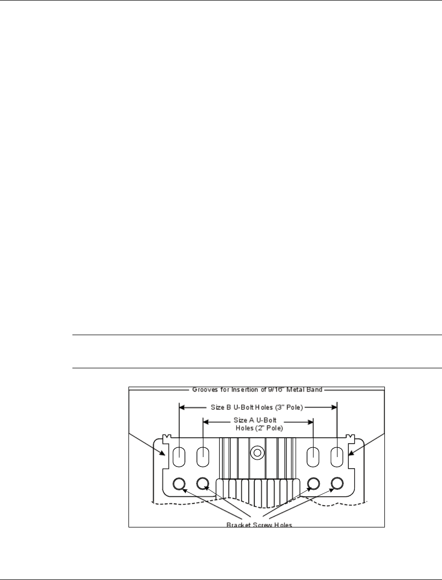
Figure 2-1 shows the locations of the U-bolt holes, band grooves and screw holes
on the rear side of the unit.
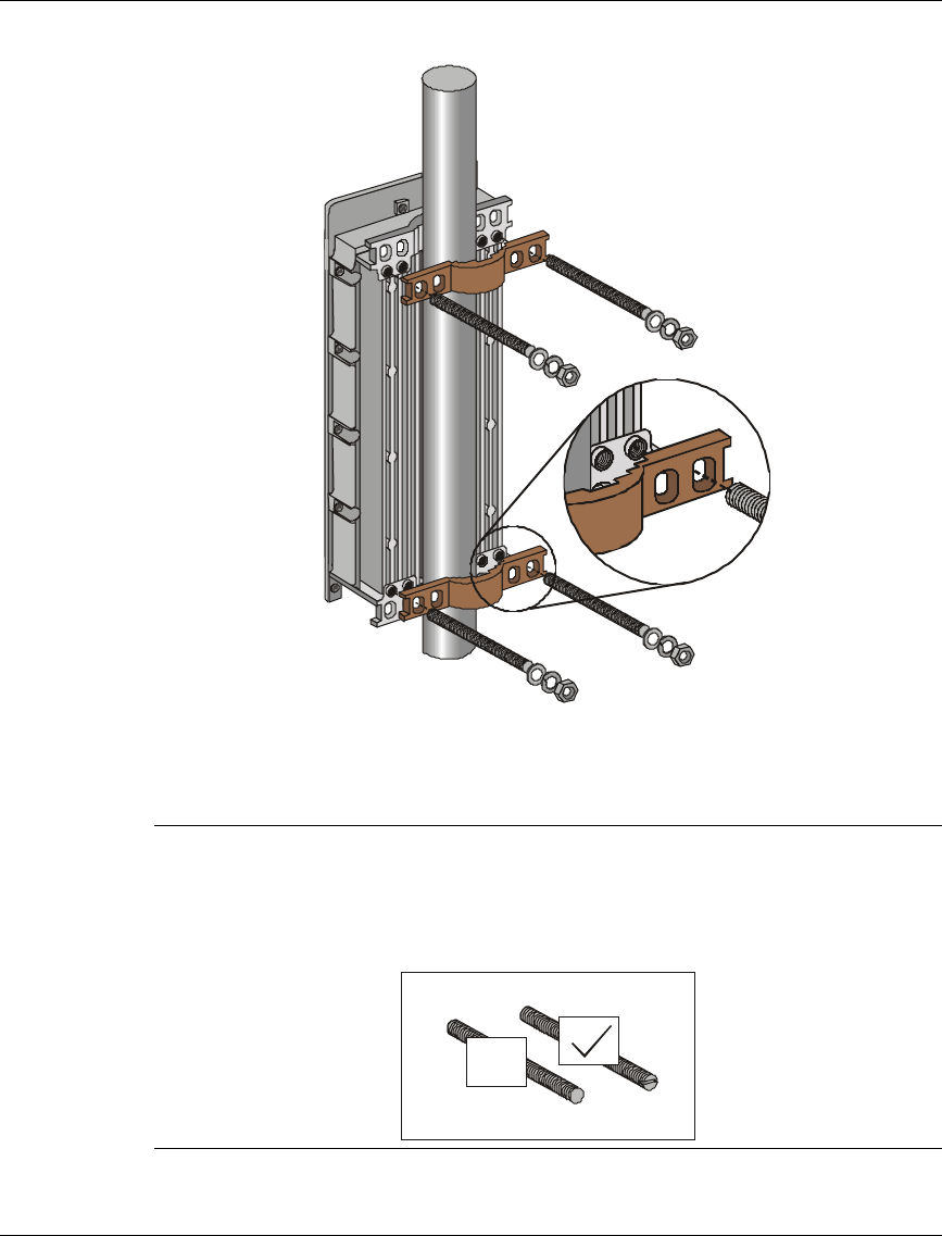
Figure 2-2 illustrates the method of installing an AU-RE unit on a pole using the
supplied brackets and open-ended screws. The installation of an AU-RA unit with
an integral antenna is very similar to the installation of an SU-RE unit.
Note: Make sure to install the unit with the bottom panel (the panel with the IF
connector) facing downward.
Bracket Screw Holes
Grooves for Insertion of 9/16” Metal Band
Size B U-Bolt Holes (3” Pole)
Size A U-Bolt
Holes (2” Pole)
Figure 2-1. Holes/Grooves/Screw Holes
Basic Installation
Base Station Equipment Installation Manual 8 BreezeACCESS Series
Figure 2-2. AU-RE 3" Pole Mounting Installation Using the
Special Brackets
Note: When inserting the open-ended screws, make sure to insert them with the
grooves pointing outwards; these grooves are intended to allow fastening
of the screws with a screwdriver.
x
Basic Installation
BreezeACCESS Series 9 Base Station Equipment Installation Manual
2.5.2 Connecting the Antenna Cable (AU-RE)
Connect an RF cable between the ANT connector (marked ANT) and the antenna.
In BreezeACCESS II and BreezeACCESS MMDS AU-RE units, the ANT
connector is located on the top panel of the unit. In BreezeACCESS XL units, the
ANT connector is located on the bottom panel.
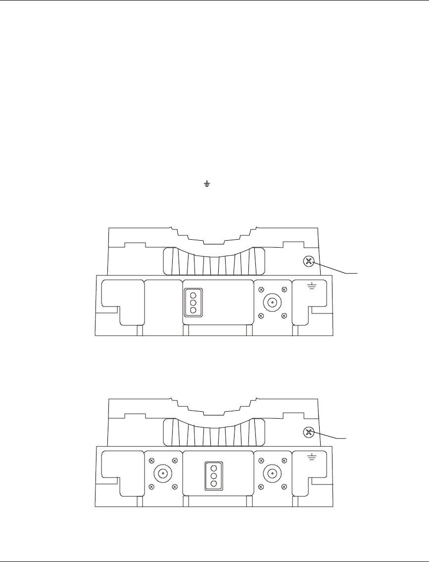
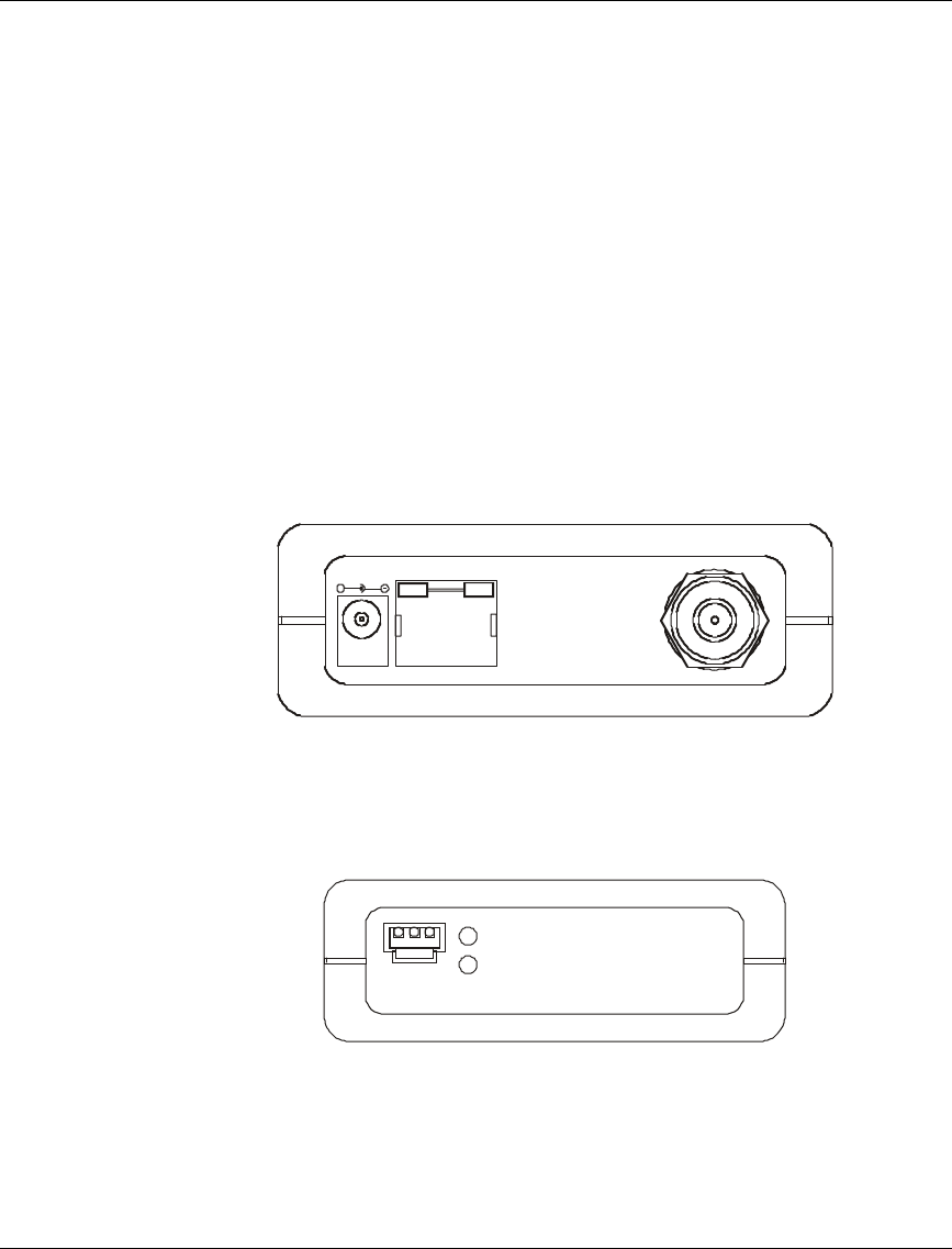
2.5.3 Connecting the Ground and IF Cables
The Ground terminal (marked ) and the IF cable connector (marked IF) are
located on the bottom panel of the Outdoor unit, shown in Figure 2-3 and in
Figure 2-4.
ETH
ALARM IF
12V IN
Figure 2-3. BreezeACCESS II and BreezeACCESS MMDS AU-RA/AU-RE
Radio Unit Bottom Panel
ETH IF
12V IN
ANT ALARM
Figure 2-4. BreezeACCESS XL AU-RE Radio Unit Bottom Panel
Ground
Screw
Ground
Screw

Basic Installation
Base Station Equipment Installation Manual 10 BreezeACCESS Series
Note: The bottom panel of the BreezeACCESS AU-RA radio unit is identical to the
one shown in Figure 2-4, but does not have the ANT connector.
1. Connect one end of the grounding cable to the Ground terminal and connect
the other end to a good ground connection.
2. Connect the coaxial cable to the IF connector. Verify that the length of the IF
cable is sufficient and that it can easily reach the Indoor unit.
Note: Make sure to switch OFF the power of the indoor unit prior to
connecting/disconnecting the IF cable.
Basic Installation
BreezeACCESS Series 11 Base Station Equipment Installation Manual
2.6 Installing the Modular Shelf Indoor Equipment
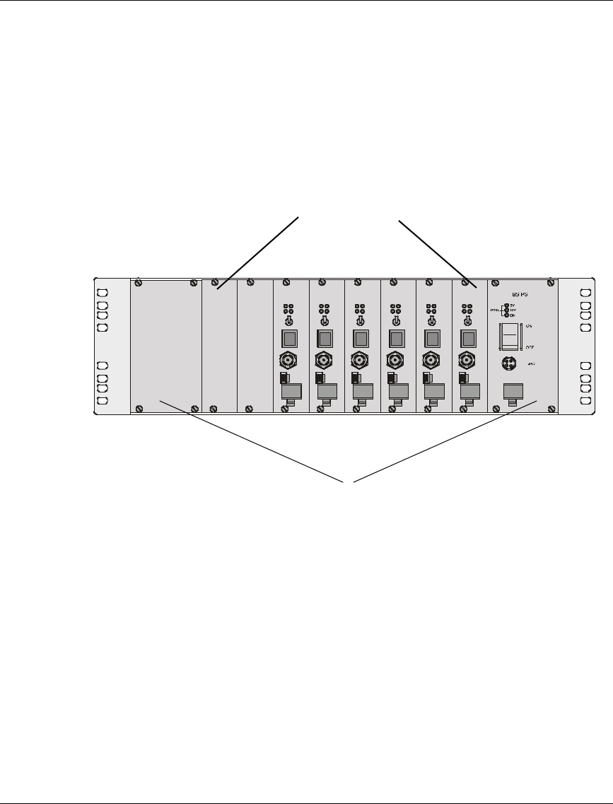
2.6.1 BS-SH Slot Assignments
The Base Station shelf has ten slots, as shown in Figure 2-5
BS-AU
MON
IF
ETH
RESET
OFF
ON
PWR
ALRM WL NK
MA ST ER
BS -AU
MON
IF
ETH
RESET
OFF
ON
PWR
AL RM WLNK
MASTER
BS-AU
MON
IF
ETH
RESET
OFF
ON
PW R
ALRM
WLNK
M ASTER
BS -AU
MO N
IF
ETH
RESET
OFF
ON
PW R
AL RM
WLNK
MASTER
BS-AU
MON
IF
ETH
RESET
OFF
ON
PW R
ALRM
WLNK
M ASTER
BS-AU
MO N
IF
ET H
RESET
OFF
ON
PW R
AL RM
WLNK
MASTER
Figure 2-5. Shelf Slot Assignments
The two wide slots on the both sides of the shelf accommodate the BS-PS power
supply modules. The shelf is designed to support power supply redundancy
through the use of two Power Supply modules. If a single power supply is used, it
can be inserted in any of the two available slots.
The remaining eight slots can accommodate up to six active BS-AU modules.
Two extra slots are for future use. Active BS-AU modules can be installed in any
of the 8 slots. Unused slots should be covered by blank panels.
8 Middle slots - BS-AU modules
Extreme slots - Power Supply modules
Basic Installation
Base Station Equipment Installation Manual 12 BreezeACCESS Series
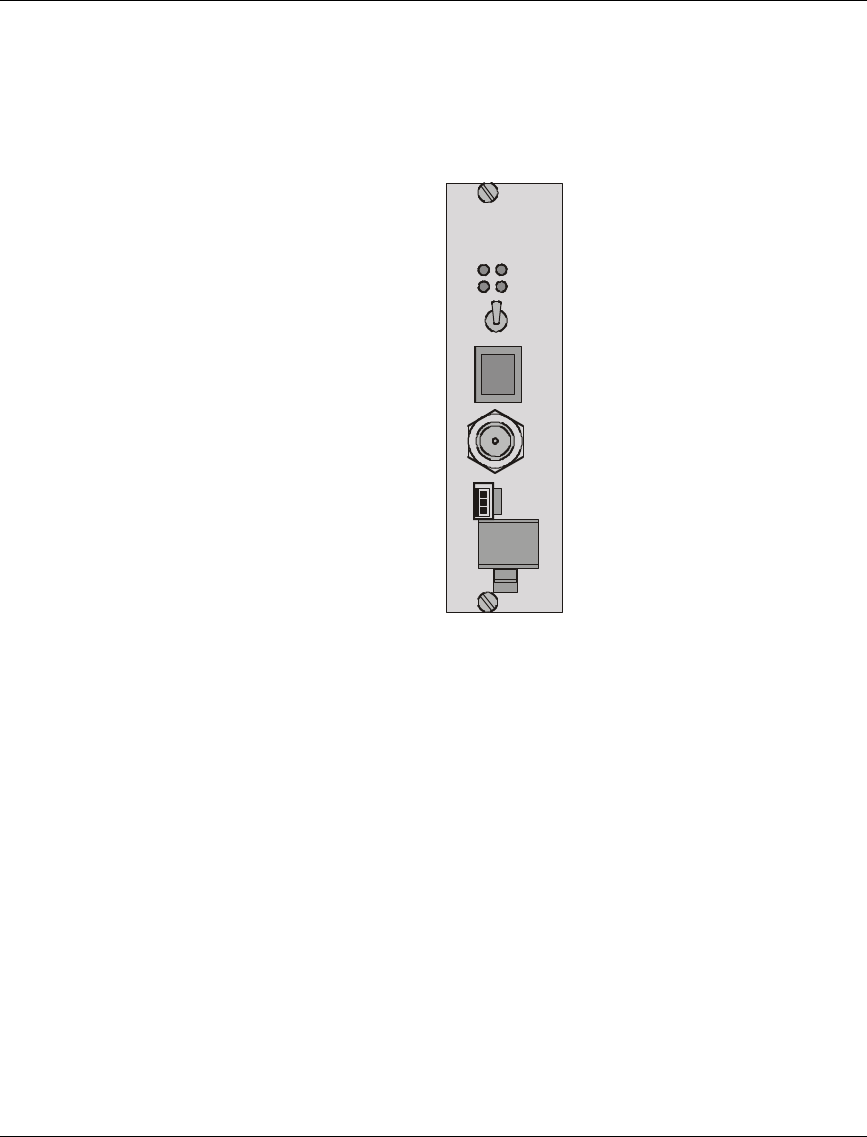
2.6.2 The BS-AU
The BS-AU front panel is shown in Figure 2-6.
BS-AU
MON
IF
ETH
RESET
OFF
ON
PWR
ALRM WLNK
MASTER
Figure 2-6. BS-AU Front Panel
The BS-AU provides the following interfaces:
An Ethernet connector (ETH) for connecting the BS-AU to the network. This
connector should be connected to a straight Ethernet cable.
An IF connector for connecting the BS-AU to an outdoor AU-RE or AU-RA radio
unit. The outdoor radio unit provides the air link between the BS-AU and the
remote Subscriber Units.
A MON connector for connecting an ASCII terminal with terminal emulation
software for configuration and maintenance purposes.

Basic Installation
BreezeACCESS Series 13 Base Station Equipment Installation Manual
The BS-AU front panel LEDs are described in Table 2-2.
Table 2-2: BS-AU LEDs
Name Description Functionality
PWR Power supply
12 VDC On – 12 VDC power is supplied to AU-RE
Off – 12 VDC power is not supplied to AU-RE
WLNK Wireless link
activity Blinking –Receiving packet from the wireless link
Off – No reception of packets from the wireless
link
ALRM ALARM
Indication On – Loss of hopping synchronization (slave units)
MASTER Master
Indication
On – The unit is configured as a Master
ETH
connector
embedded
(orange)
LED
Ethernet
activity
On- Receive/Transmit on Ethernet port
Off- No Receive/Transmit on Ethernet port
ETH
connector
embedded
(green)
LED
ETH Link
Integrity
On- Unit is connected to Ethernet segment
Off- Unit is not connected to Ethernet segment
The switch on the BS-AU front panel controls the supply of 12 VDC power to the
outdoor unit via the IF cable. The momentary RESET position of this switch is
for resetting the outdoor unit. In the OFF position, power is not supplied to the
outdoor unit, even when the BS-AU unit is still ON.
Basic Installation
Base Station Equipment Installation Manual 14 BreezeACCESS Series
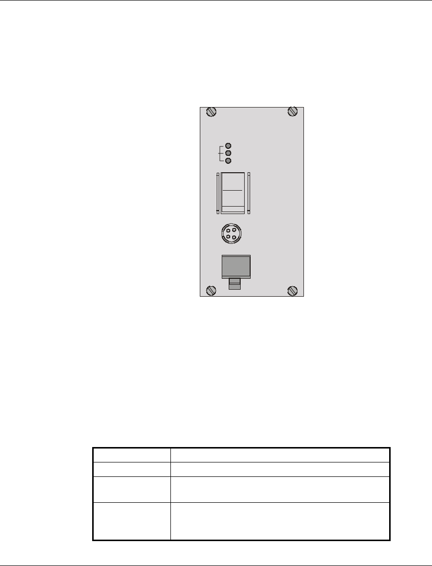
2.6.3 The BS-PS
The BS-PS provides power to all the modules installed in the BS-SH rack. The
BS-PS front panel is shown in Figure 2-7.
BS-PS
OFF
ON
-48V
12V
5V
ON
PWR
Figure 2-7. BS-PS Front Panel
The BS-PS provides a single connector (marked -48V) for connecting the -
48VDC power source to the module. The color codes of the cable wires are:
black -48VDC
red + (Return)
The switch turns the mains power to the power supply ON and OFF.
Table 2-3. BS-PS Power Supply LEDs
Name Description
ON -48 VDC is available and Power Supply is ON
5V The 5V power supply module is OK and power
is consumed (at least one BS-AU module is inserted)
12V The 12V power supply module is OK and
power is consumed (at least one AU-RA/RE unit is
connected)

Basic Installation
BreezeACCESS Series 15 Base Station Equipment Installation Manual
2.6.4 Shelf and Modules Installation Procedure
1. Install the BS-SH rack in a 19" cabinet (or place on an appropriate
shelf/table). When mounting the BS-SH on a desktop, screw on the rubber
legs shipped with unit.
2. Carefully insert the BS-PS Power Supply and the BS-AU modules into their
intended slots and push firmly until they are securely locked; refer to
Section 2.6.1 for a description of the slot assignments. Close the captive
screws attached to each module. Place blank covers over all the unused
slots.
3. Connect the IF cable(s) to the connector(s) marked IF located on the front
panel(s) of the BS-AU module(s) shown in Figure 2-6. The other side of the
IF cable should already be connected to the outdoor unit.
4. Connect the DC power cord to the –48 VDC In jack (marked –48V) located
on the front panel of the BS-PS power supply shown in Figure 2-7. If a
redundant power supply module is installed, connect a power cable to it as
well.
5. Connect the power cord(s) to the –48VDC power source. Connect the black
wire to the -48VDC contact of the power source. Connect the red wire to the
+ (Return) contact. Connect the shield to the Ground.
6. Switch the BS-PS power supplies to ON. Verify that all the power indicator
LEDs on the BS-PS front panel are ON. Refer to Table 2-3 for a description
of these LEDs.
7. Set the switches on the front panel of all BS-AU modules in the rack to ON.
Note: Disconnect the IF cable from the BS-AU module before inserting or
removing it to/from the BS-SH shelf.
Basic Installation
Base Station Equipment Installation Manual 16 BreezeACCESS Series
2.7 Installing the AU-NI Indoor Unit
1. Place the AU-NI unit in an appropriate location on a shelf or a table. The unit
can be wall mounted using the installation materials provided with the unit.
Use a 6mm (1/4") drill and the supplied template plate for easy and accurate
marking of the holes.
2. Connect the AU -PS DC power cord to the DC In jack (marked DC-12V)
located on the rear panel of the Indoor unit (shown in Figure 2-7).
3. Connect the IF cable to the IF connector (marked IF) on the rear panel of the
Indoor unit. The other side of the IF cable should already be connected to the
Outdoor unit.
4. Connect the mains power cord to the AU -PS. Connect the mains power plug
to a mains power outlet.
+
DC - 12V ETH IF
Figure 2-8. AU -NI Rear Panel
5. Verify that the Power LED (marked PWR) located on the front panel of the
Indoor Unit is turned ON.
PWR
WLNK
MON
Figure 2-9. AU -NI Front Panel
6. Use a straight Ethernet 10baseT cable to connect the base station network
(e.g., a hub, switch or router) to the Ethernet port (marked ETH) located on
the rear panel of the AU-NI unit.

Configuring System Parameters
BreezeACCESS Series 17 Base Station Equipment Installation Manual
3. CONFIGURING SYSTEM PARAMETERS
After completing the installation process as described in the preceding section,
proceed with configuration of the basic system parameters.
This section covers the configuration of basic installation parameters. Refer to the
Administration Manual for information related to other parameters.
Note: Optionally, the product can be configured using Telnet over the Ethernet
port. See Appendix A of this manual for further information.
3.1 Getting Started with the Local Terminal
1. Connect one end of the Monitor cable to the MON jack on the front panel of
the BS-AU module or the AU-NI unit. Connect the second end of the cable to
the COM port of the terminal. The COM port connector on the Monitor cable
is a 9 pin D-type plug.
2. Run a terminal emulation program (e.g., ProComm or Windows
HyperTerminal) using the following setup:
Baud rate 9600
Data bits 8
Stop bits 1
Parity None
Flow Control Xon/Xoff
Connector Available Com Port
3. Press Enter. The Select Access Level menu appears. Select the access level
according to your authorized access level. You will be requested to enter
your password. After entering the correct password, press the Enter key.
The main menu appears as shown in Figure 3-1

Configuring System Parameters
Base Station Equipment Installation Manual 18 BreezeACCESS Series
Software
Version No.
BreezeACCESS/BST-AU
Official Release Version – 3.0.2
Release Date: Mon Oct 23 21:05:08 2000
Main Menu
1 – Info Screens
2 – Unit Control
3 – Basic Configuration
4 – Site Survey
5 – Advanced Configuration
>>>
Figure 3-1. Main Menu
The appearance of the displayed Main Menu varies in accordance with the access
level.
• For users with read only access rights, only the Info Screens option is
displayed. Users with this access level cannot access the Unit Control,
Basic Configuration, Site Survey and Advanced Configuration menus.
• For users with Installer access rights, the first four menu items (Info
Screens, Unit Control, Basic Configuration and Site Survey) are
displayed. Users with this access level cannot access the Advanced
Configuration menu.
• For users with Administrator access rights, the full Main Menu will be
displayed. These users can access all the menu items.
Unit Type

Configuring System Parameters
BreezeACCESS Series 19 Base Station Equipment Installation Manual
4. Operate the monitor program as follows:
• Type an option number to open/activate the option. You may need to
press the Enter key in some cases.
• Press the Esc key to exit a menu or an option.
• You can log-out and exit the monitor program from the Main Menu
by simultaneously pressing the Ctrl and X keys. The session is
terminated automatically after a specific time of inactivity,
determined by the Log-out Timer. The default value for the Log-out
Timer is 5 minutes.
• Reset the unit after making configuration changes for the new values
to take effect.
• You can view the current parameters’ configuration by selecting 1 in
the Main Menu to Access the Info Screens menu, and then selecting
2 in the Info Screens menu to view the Basic Configuration
parameters.
3.2 Configuring Basic Parameters
The Basic parameters that must be properly configured in all Access Units during
the installation process include the ESSID, IP related parameters and frequency
related parameters. Proper configuration of these parameters is essential in order
to guarantee connectivity with the Subscriber Units, allowing remote configuration
of other parameters via either the wired or the wireless network. Configure the
following parameters according to the instructions supplied by the system
administrator:
• Parameters common to all product lines:
⇒ ESSID
⇒ IP Parameters: DHCP Client and/or IP Address, Subnet Mask and
Default Gateway Address

Configuring System Parameters
Base Station Equipment Installation Manual 20 BreezeACCESS Series
• Parameters specific to BreezeACCESS II Access Units:
⇒ Hopping Sequence
⇒ Hopping Set
⇒ Hopping Sync (if using more than one AU-BS)
• Parameters specific to BreezeACCESS XL Access Units:
⇒ Hopping Band
⇒ Frequency Offset
⇒ Flexible Hopping Definition
Note: There are several ways to define the hopping frequencies using various
subsets of the above parameters. The parameters to be used depend on the
specific model as well as on specific system requirements, as determined by
the system administrator.
⇒ Hopping Shift (if using more than one AU-BS)
⇒ Hopping Sync (if using more than one AU-BS)
• Parameters specific to BreezeACCESS MMDS Access Units:
⇒ Flexible Hopping Definition
⇒ Hopping Shift (if using more than one AU-BS)
⇒ Hopping Sync (if using more than one AU-BS)
Note: You must select Reset Unit in the Unit Control menu for the changes to take
effect.
See Appendix B for more details on the basic parameters.

Configuring System Parameters
BreezeACCESS Series 21 Base Station Equipment Installation Manual
3.2.1 Configuring Parameters Common to All Product Families
1. From the main menu, type 3 to access the Basic Configuration menu.
2. From the Basic Configuration menu, type D to access the DHCP Client
menu. Type 1 to access the DHCP Options menu and select the required
option. If the option was selected to other than Disable, type 2 to access the
Access to DHCP menu and select the required option. If the DHCP Only
option was selected, go to step 6. Otherwise (if either the Disable or
Automatic options were selected), perform steps 3-5.
3. Type 1 to access the IP Address selection screen. Enter the required IP
address.
4. Type 2 to access the Subnet Mask selection screen. Enter the required subnet
mask.
5. Type 3 to access the Default Gateway Address selection screen. Enter the
required default gateway address.
6. Type 4 to access the ESSID selection screen. Enter the required ESSID.
7. For BreezeACCESS II units, proceed to Section 3.2.2. For BreezeACCESS
XL units, proceed to Section 3.2.3. For BreezeACCESS MMDS units,
proceed to Section 3.2.4.
3.2.2 Configuring Parameters Specific to BreezeACCESS II
1. Type 7 to access the Hopping Sequence menu. Enter the required hopping
sequence.
2. Type 8 to access the Hopping Set selection screen. Enter the required
hopping set.
3. If more than one AU-BS is used, they should be synchronized for optimal
spectrum utilization. Type 6 to access the Hopping Sync selection screen.
Enter the required hopping sync status (Master or Slave).
Note: Only one AU should be defined as a Master. The other units should be
defined as Slaves. If only one AU is used, it should be defined as Idle.

Configuring System Parameters
Base Station Equipment Installation Manual 22 BreezeACCESS Series
3.2.3 Configuring Parameters Specific to BreezeACCESS XL
1. Type H to access the Hopping Band selection screen. (if this screen is
available).Select the required option.
2. If the selected Hopping Band option was one of the fixed bandwidths
(10MHz, 12MHz,…) or Single Channel, type 8 to access the Frequency
Offset selection screen. Enter the required value.
3. If the selected Hopping Band option was Flexible Hopping Definition, or if
the Hopping Band option is not available in this model, type F to access the
Flexible Hopping Definition menu. Type 2 to access the Channel Spacing
selection screen (if available), and select the required value. Type 1 to
access the Define Sub-bands option and enter the required dub-
bands/frequencies. To verify that the required sub-bands/frequencies were
entered properly, type S to view the selected Sub-bands/frequencies.
If more than on AU-BS is used, they should be synchronized for optimal spectrum
utilization, as follows:
1. Type 6 to access the Hopping Sync selection screen. Enter the required
selection (Master or Slave)
2. Type 7 to access the Hopping Shift selection screen. Enter the required
value.
Note: Only one AU should be defined as Master. The other units should be defined as
Slaves. If only one AU is used, it should be defined as Idle.

Configuring System Parameters
BreezeACCESS Series 23 Base Station Equipment Installation Manual
3.2.4 Configuring Parameters Specific to BreezeACCESS MMDS
1. Type F to access the Flexible Hopping Definition menu. Enter the required
Channels/frequencies. See Appendix C for a list of the standard MMDS
channels and frequencies.
2. If more than one AU-BS is used, they should be synchronized for optimal
spectrum utilization. Type 6 to access the Hopping Sync selection screen and
enter the required option (Master or Slave). Type 7 to access the Hopping
Shift selection screen, and enter the required value.
Note: Only one AU should be defined as Master. The other units should be
defined as Slaves. If only one AU is used, it should be defined as Idle.
3.3 Reset Unit
1. From the main menu, type 2 to access the Unit Control menu.
2. Type 1 to access the Reset Unit menu. Type 1 to reset the unit so that new
configuration settings are applied.
Note: Should you make any mistakes during configuration or encounter any
problems associated with system configuration parameters, you may
configure the unit back to the factory defaults, as follows:
Type 2 in the Unit Control menu to access the Set Factory Defaults menu.
Type in 2 (Set Factory defaults-Full) to load the default values. Reset the
unit for the factory defaults values to take effect.

Verifying Correct Operation
Base Station Equipment Installation Manual 24 BreezeACCESS Series
4. VERIFYING CORRECT OPERATION
4.1 Verifying Correct Operation of the AU-A/E-BS
After completing the installation as described above, the system starts operation.
To verify correct operation, view the LED indicators located on the front panel of
the BS-AU modules as shown in Table 2-2 on page 13.
Note: If the Access Units are not synchronized, reset the Master BS-AU unit and
then the Slave units to re-synchronize them.
4.2 Verifying Correct Operation of the AU-A/E-NI
To verify proper operation, view the LED indicators located on the front and rear
panels of the AU-NI unit as described in Table 4-1.
Table 4-1. AU-NI LEDs
Name Description Functionality
PWR Power Supply
12VDC On – 12VDC power is supplied to the AU-NI
Off –Power is not supplied to the AU-NI
WLNK Wireless link
activity Blinking –Receiving packet from the
wireless link
Off – No reception of packets from the
wireless link
ETH connector
embedded
(green) LED
Ethernet
activity On – Receive/transmit on Ethernet port
Off – No receive/transmit on Ethernet port
ETH connector
embedded
(orange) LED
Ethernet
integrity On – Unit is connected to Ethernet segment
Off – Unit is not connected to Ethernet
segment

Verifying Correct Operation
BreezeACCESS Series 25 Base Station Equipment Installation Manual
4.3 Verifying Correct Operation of the Outdoor Unit
To verify proper operation, view the LED indicators located on the bottom panel
of the Outdoor unit as shown in Figure 2-3 on page 9.
Table 4-2 lists the various LED states.
Table 4-2. AU-RA/RE LEDs
Name Description Functionality
ALARM Alarm
Indication On – A problem with the power amplifier or in
the locking process of any of the synthesizers
Off –Normal operation
12V IN 12V DC power
supply On – 12VDC power is supplied to the unit
Off – 12VDC is not available
ETH Ethernet activity Blinking – Data received from or transmitted to
Ethernet LAN
Off – No activity on the Ethernet LAN
Note: Verifying proper operation of the outdoor unit using the LEDs as described
above is possible only after completion of the configuration process.
Specifications
Base Station Equipment Installation Manual 26 BreezeACCESS Series
5. SPECIFICATIONS
5.1 Radio
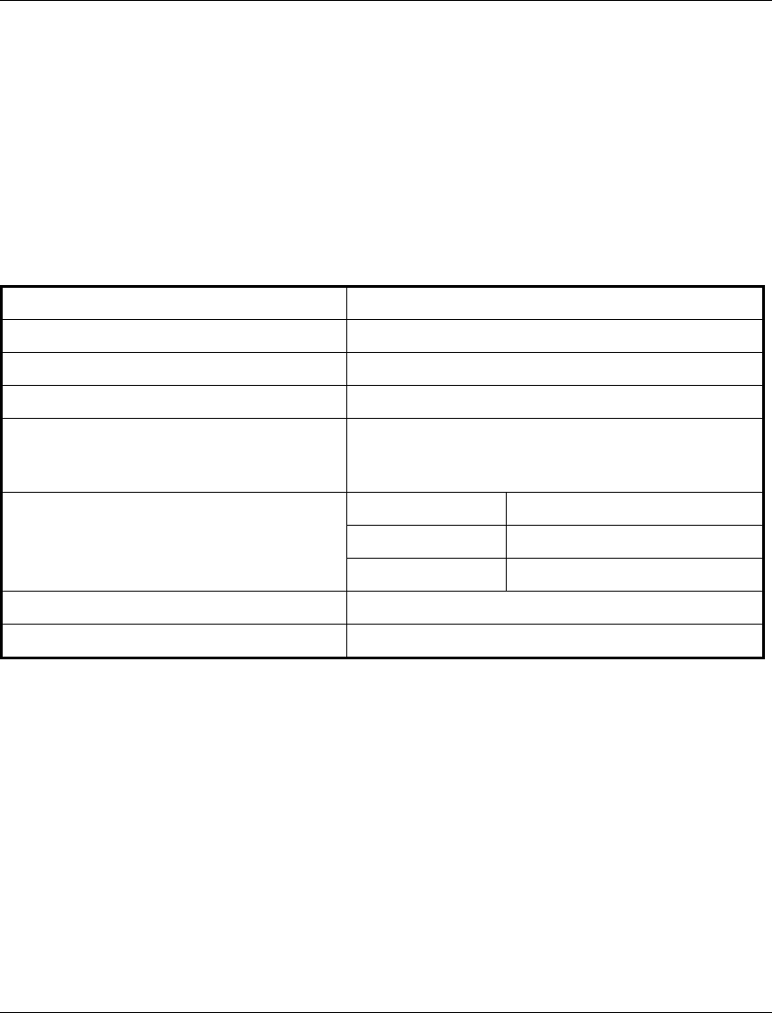
5.1.1 BreezeACCESS II
Frequency 2.4GHz ISM band
Radio Access Method FH-CDMA
Operation Mode Time Division Duplex
Channel Bandwidth 1 MHz
Output Power (at antenna port) 26 dBm (HP) or 15dBm (GP) or 7dBm (MP) or
2 dBm (LP) typical.
Power Control range: 20 dB
Sensitivity 1Mbps -87
(dBm at antenna port, BER 1E10-6) 2Mbps -81
3Mbps -73
Data Rate 3Mbps max
Modulation Multilevel GFSK
Specifications
BreezeACCESS Series 27 Base Station Equipment Installation Manual
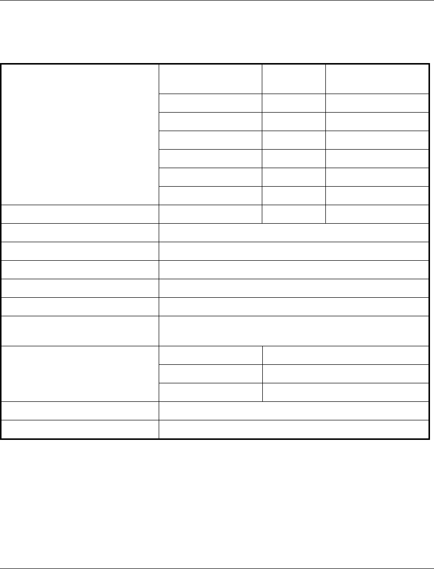
5.1.2 BreezeACCESS XL
Frequency Model Uplink Band
(GHz) Uplink-Downlink
Separation (MHz)
BreezeACCESS 3.5a 3.410-3.452 100
BreezeACCESS 3.5a1 3.400-3.450 100
BreezeACCESS 3.5b 3.450-3.500 100
BreezeACCESS 3.5e 3.425-3.450 50
BreezeACCESS 2.6b 2.551-2.593 74
BreezeACCESS 3.3 3.300-3.324 76
BreezeACCESS 3.8 3.925-4.015 -320
Radio Access Method FH-CDMA
Operation Mode and Standard Frequency Division Duplex, EN 301 253
Bandwidth Allocation Up to 50MHz (CEPT 14-03, CEPT 12-08)
Channel Bandwidth 2 MHz
Sub-channel Spacing 2 MHz, 1.75 MHz, 1 MHz (depending on model)
Output Power (at antenna port) 27 dBm typical.
Power Control range: 20 dB
Sensitivity 1Mbps -93
(dBm at antenna port, BER 1E10-6) 2Mbps -86
3Mbps -78
Data Rate 3Mbps max
Modulation Multilevel GFSK
Specifications
Base Station Equipment Installation Manual 28 BreezeACCESS Series
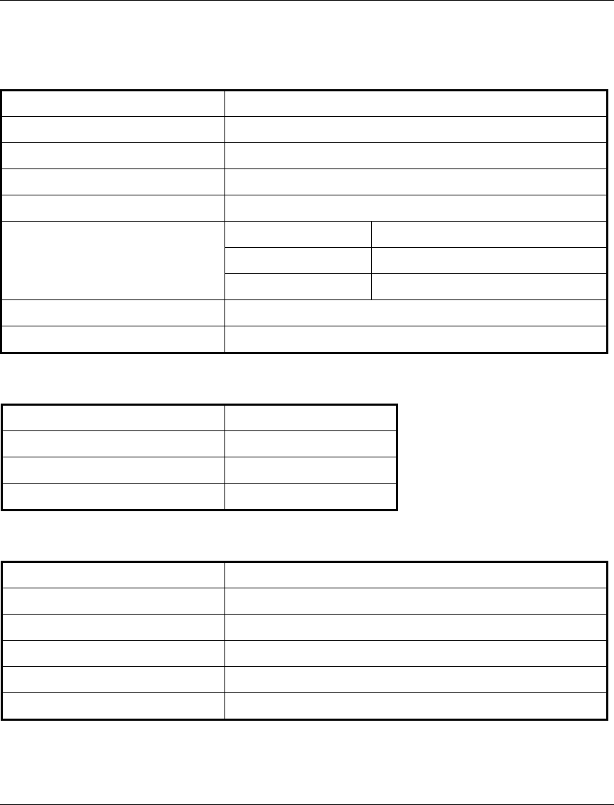
5.1.3 BreezeACCESS MMDS
Frequency 2.500GHz –2.686GHz
Radio Access Method FH-CDMA or TDMA
Operation Mode Time Division Duplex
Channel Bandwidth 2 MHz
Output Power (at antenna port) 29 dBm typical. Power Control range – 20 dB
Sensitivity 1Mbps -93
(dBm at antenna port, BER 1E10-6) 2Mbps -86
3Mbps -78
Data Rate 3Mbps max
Modulation Multilevel GFSK
5.2 Outdoor Unit to Indoor Unit Communication
IF Frequency 440 MHz
IF cable Impedance 50 ohm
Maximum IF cable Attenuation 15dB
Maximum IF cable DC Resistance 1.5 ohm
5.3 Configuration and Management
Local Management Via MON port, Monitor program using terminal emulation
Remote Management SNMP, Telnet, TFTP
Remote Management Access From Wired LAN, Wireless Link
SNMP Agents MIB II, Bridge MIB, Private MIBs
Security Authentication and filtering
Software upgrade TFTP download

Specifications
BreezeACCESS Series 29 Base Station Equipment Installation Manual
5.4 Interfaces
Interface Outdoor Unit Indoor Equipment
RF (AU-E) N-Type jack lightning protected
IF TNC jack, lightning protected TNC jack, lightning protected
Ethernet 10BaseT (RJ-45) with two embedded LEDs
Monitor 3-pin low profile
Power 12 VDC via the IF cable 4-pin power connector (BS-PS)
DC plug for the AU-PS power supply (AU-NI)
5.5 Electrical
Outdoor Unit 12 VDC via the IF cable
Indoor Modular Shelf Equipment -48 VDC, 200 W for a fully equipped shelf
AU (Indoor + Outdoor): 25W
Indoor AU-NI Unit AU-NI: 12VDC/2.5A from AU-PS
AU-PS: 100 - 240 VAC, 47-63 Hz
5.6 Mechanical
Outdoor Unit AU-RE: 30cm x 12cm x 5cm, 2.2 kg
AU-RA: Depending on specific model
Indoor Modular Shelf Equipment BS-SH: 19",3U, depth 26cm, 6 kg. Fully loaded
Indoor AU-NI Unit AU-NI: 13cm x 8.6cm x 3cm, 0.5 kg
AU-PS: 10cm x 6.5cm x 3.5cm, 0.4 kg
Specifications
Base Station Equipment Installation Manual 30 BreezeACCESS Series
5.7 Environmental
Outdoor Unit Indoor Equipment
Operating Temperature -400C to 600C0
0C to 450C
Operating Humidity 5%-95% non-condensing
Weather protected 5%-95% non condensing
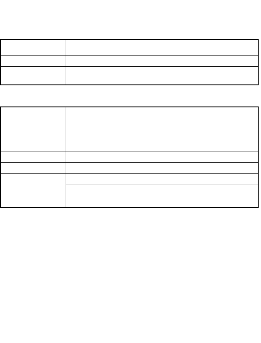
5.8 Standards Compliance, General
Type Unit Standard
EMC BreezeACCESS II FCC Part 15.247, EN 300 826 (LP models)
BreezeACCESS MMDS FCC Part 15.247
BreezeACCESS XL ETS 300 385
Safety All Products UL 1950, EN 60950
Environmental All Products ETS 300 019
Radio BreezeACCESS II FCC Part 15.247, ETS 300 328 (LP)
BreezeACCESS MMDS FCC Part 21
BreezeACCESS XL EN 300 253 (V 1.1.1), RSS 192
Appendix A. Using Telnet
BreezeACCESS Series 31 Base Station Equipment Installation Manual
APPENDIX A. USING TELNET
Use the following procedure to connect to BreezeACCESS units via a Telnet
session.
1. Connect the PC to the Ethernet port of the unit (or the hub to which the unit is
connected) using a straight Ethernet cable. If you connect the PC directly to a
unit that is normally connected to a hub, use a crossed Ethernet cable. You
may also connect the PC to any Ethernet port on the network and
communicate with the unit to be managed via the wired or wireless media.
2. Make sure that the PC’s IP parameters (IP address and subnet mask) are
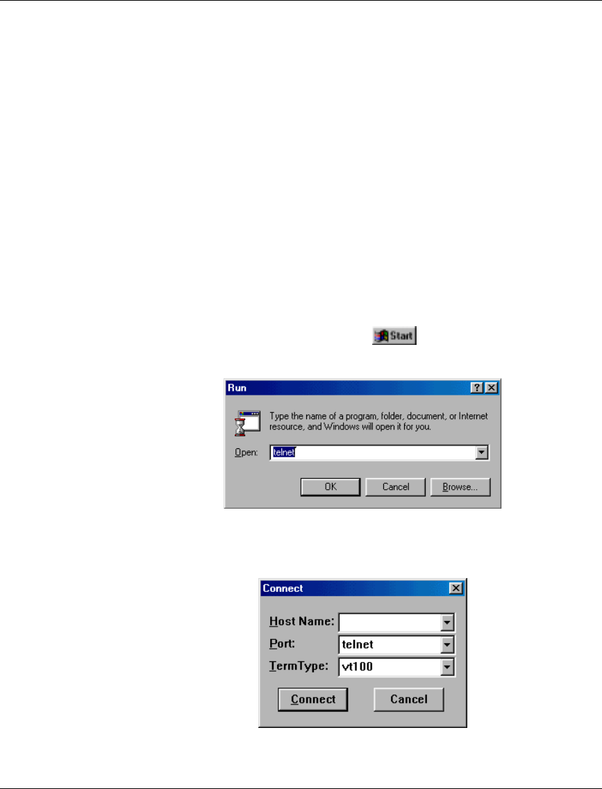
configured to enable connectivity with the unit.
3. Start the Telnet application by selecting , Run and then typing Telnet
in the Run dialog box.
4. Select Connect-Remote System from the Telnet window menu. The following
dialog box is displayed.
Appendix A. Using Telnet
Base Station Equipment Installation Manual 32 BreezeACCESS Series
5. In the Host Name field, enter the IP address of the unit to be managed.
6. Set the Port field to Telnet (this is the default).
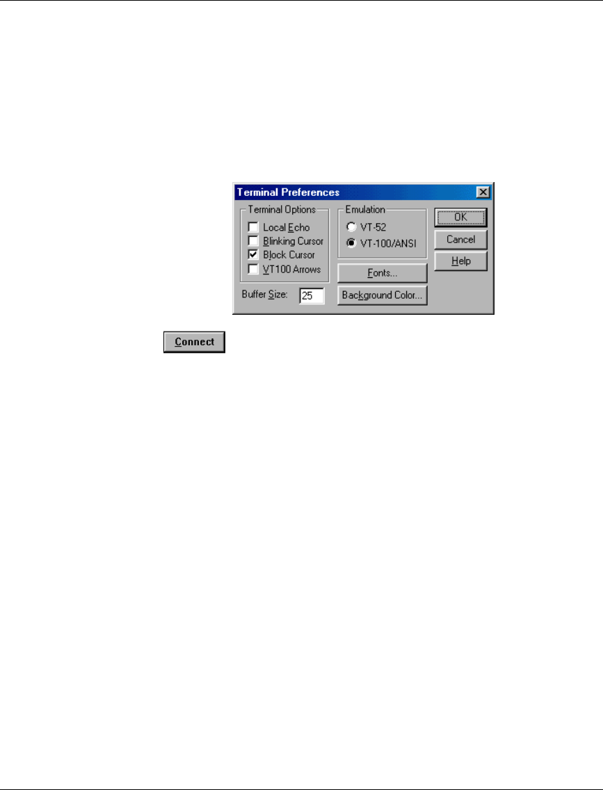
7. Set the Terminal Type to VT100 (this is the default). If the VT100 option in
not available, do the following. Select Terminal-Preferences from the Telnet
window menu and click the VT-100/ANSI radio button (as shown below).
8. Click in the Connect dialog box. The Select Access Level of the
Monitor program should be displayed.
9. To exit the Telnet session, choose Disconnect from the Connect menu.
(The session is terminated automatically, after a specific time of inactivity is
determined by the Log-out Timer).

Appendix B. Basic Parameters
BreezeACCESS Series 33 Base Station Equipment Installation Manual
APPENDIX B. BASIC PARAMETERS
The following parameters are relevant to all BreezeACCESS products.
• IP Address – Displays the current IP address of the unit and allows entry of
a new IP address (4 x 3 digit octets, separated by dots). The default IP
Address is 010.000.000.001.
• Subnet Mask – Displays the current subnet mask of the unit and allows
entry of a new subnet mask (4 x 3 digit octets, separated by dots). The
default mask is 255.000.000.000.
• Default Gateway Address – Displays the current address of the default
gateway of the unit and allows entry of a new default gateway address (4 x 3
digit octets, separated by dots). The default gateway address is
000.000.000.000.
• ESS ID – The ESSID (Extended Service Set ID) of the unit (up to 32
printable ASCII characters). The ESSID is a string used to identify a wireless
network. It prevents the unintentional merging of two co-located wireless
networks. An SU can only associate with an AU that has an identical ESSID.
Use different ESSIDs to segment the wireless access network and add
security to your network. The default value is ESSID1.
Note: The ESSID string is case-sensitive.
• DHCP Client
⇒ DHCP Options – Displays the current status of the DHCP (Dynamic
Host Configuration Protocol) support, and allows selecting a new
operation mode. The available options are:
∗ Disable – Use manual procedure for configuring the IP
parameters.
∗ DHCP Only – Search for a DHCP Server and obtain the IP
parameters from it (IP Address, Subnet Mask and Default
Gateway Address).

Appendix B. Basic Parameters
Base Station Equipment Installation Manual 34 BreezeACCESS Series
∗ Automatic – Search for a DHCP Server for configuration of
the IP parameters. If a DHCP Server is not found within
approximately 40 seconds, use the currently configured IP
parameters.
The default is Disable.
⇒ Access to DHCP - To define the port through which the unit is
allowed to communicate with a DHCP server. The options are the
following:
∗ From Wlan Only
∗ From Ethernet Only
∗ From Both Ethernet & Wlan
The default for an Access Unit is From Ethernet Only. The
default for a Subscriber Unit is From Wlan Only.
Parameters Specific for BreezeACCESS II
The following parameters are set in BreezeACCESS II products.
• Hopping Sequence – Displays the Hopping Sequence of the unit.
A hopping sequence is a pre-defined series of channels (frequencies) that are
used in a specific, pseudo-random order as defined in the sequence. The unit
“hops” from frequency to frequency according to the selected sequence.
When more than one AU is co-located in the same area, it is recommended to
assign different hopping sequences to each AU.
Hopping Sequences are grouped in three hopping sets (see Hopping Set
parameter below). When setting up multiple AUs in the same site, always
choose hopping sequences from the same Hopping Set to reduce the
possibility of collisions on the wireless media. This parameter is only set in
the AU. All the SUs learn it from the AU during the association process.
The permitted range depends on the applicable hopping standard (see Table
5-1 on the next page). The default value is 1.

Appendix B. Basic Parameters
BreezeACCESS Series 35 Base Station Equipment Installation Manual
• Hopping Set – Displays the selected hopping set. Each hopping standard has
3 hopping sets. The hopping set selected in this screen determines which
hopping sequences are available in the Hopping Sequence screen. Always
use the same hopping set per site (with different hopping sequences) to
minimize the possibility of collisions on the wireless media. The default
value is 1.
This parameter is set only in the AU. All the associated SUs learn its value
from the AU during the association process.
• Hopping Sync (BS-AU only) – Displays the current Hopping Sync status of
the unit and allows defining a new status. When several AUs that use the
same hopping set and different hopping sequences are co-located, their
operation should be synchronized in terms of hopping sequence initialization
and timing. One unit must be specified as a Master Unit and all other units
must be specified as Slave units. Available options are:
⇒ Idle – No synchronization (stand-alone operation)
⇒ Master – The AU that serves as a Master unit providing
synchronization signals to the Slave units
⇒ Slave – An AU that operates as a Slave
The default is Idle.
Note: Synchronization is not allowed by the radio regulations in certain
countries. In units using such standards, the Hopping Sync option is
not supported. See Table 5-1 for information on synchronization
support in the standards of various countries.

Appendix B. Basic Parameters
Base Station Equipment Installation Manual 36 BreezeACCESS Series
Table 5-1. Country Standards Supported by BreezeACCESS II
Country
Standard Frequency
Range [MHz] Number of
Channels Hopping
Sequences
per Hopping
Set
Hopping
Sync
Support
Australia 2400 to 2463 60 20 No
Canada 2450 to 2483.5 30 10 No
Europe ETSI 2400 to 2483.5 79 26 Yes
France 2446 to 2483.5 35 11 Yes
Israel 2418 to 2457 35 11 Yes
Korea 2427 to 2454 23 4 Yes
Japan 2470 to 2497
or
2400 to 2483.5
23
or
79
4
or
26
Yes
Netherlands 2452 to 2470 15 5 Yes
Spain 2447 to 2473 27 9 Yes
US FCC 2400 to 2483.5 79 26 No
Mexico 2450 to 2483.5 30 10 Yes
Rest of America 2400 to 2483.5 79 26 Yes

Appendix B. Basic Parameters
BreezeACCESS Series 37 Base Station Equipment Installation Manual
Parameters Specific for BreezeACCESS MMDS
The following parameters are set in BreezeACCESS MMDS products.
• Hopping Shift –Displays the current value of the hopping shift parameter
and allows entry of a new hopping shift value. This parameter is available
only in Access Units – the Subscriber Units learn it during the association
process.
When several Access Units that use the same hopping frequencies are
collocated, the Hopping Shift parameter is used to define a different hopping
sequence for each AU. The target is to achieve a minimal level of cross
interference between AUs through maintaining a minimal distance of 3 MHz
between the frequencies used by adjacent AUs at any given moment. Thus,
the collocated AUs should use different hopping shifts.
The available range for hopping shifts is dependent on the number of
frequencies selected and is equal to the number of hopping frequencies -1
(minus 1). The Hopping Shift parameter does not have any effect when using
a single frequency. The default value of the Hopping Shift parameter is 0.
• Flexible Hopping Definition – Allows adding and removing frequencies to
the list of hopping frequencies; displays the selected hopping frequencies and
the current hopping sequence (based on the previous selections made before
the last Reset). The new selections will come into effect only after the next
Reset.
The Flexible Hopping is based on using the standard MMDS 6MHz channels
and frequencies. See Appendix C for a detailed list of the standard channels,
as well as the frequency band and the hopping frequencies for each of these
channels.
The Flexible Hopping menu includes the following options, allowing
adding/removing standard MMDS channels or adding/removing discrete
standard hopping frequencies.

Appendix B. Basic Parameters
Base Station Equipment Installation Manual 38 BreezeACCESS Series
⇒ Add Frequencies – Allows adding discrete hopping frequencies or
frequency ranges. Enter a list of frequencies and/or frequency ranges
to be added, e.g. 2501.500,2407.500-2519.500, 2525.500.Use a
comma to separate between entries (no spaces). The allowed entries
are from 2500 to 2688 in steps of 0.5MHz. The frequencies (either the
start and stop frequencies of a range or discrete frequencies) can be in
the following formats:
MHz Resolution, e.g. 2520
kHz resolution, e.g. 2501.000,2505.500 (you must enter 3 digits after
the dot).
The minimal channel spacing between frequencies is 3MHz. When
entering a range, this will be the default channel spacing (e.g. for the
range 2510-2516 the hopping frequencies will be 2510, 2513 and 2516
MHz).
It is recommended to use the standard MMDS frequencies. See
Appendix C for a list of the standard MMDS frequencies.
⇒ Remove Frequencies - Allows removing frequencies from the
existing list. Enter a list of frequencies and/or frequency ranges to be
removed, using the same guidelines as in Add Frequencies above
⇒ Add Channels – Allows defining a new list of channels or adding
channels to an existing list. Enter a list of channels to be added, e.g.
A1,B3,D2. Use a comma to separate between entries (no spaces). See
Appendix C for a list of the channels and the hopping frequencies for
each of the channels.
⇒ Remove Channels – Allows removing channels from existing list.
Enter a list of channels to be removed, using the same guidelines as in
Add Channels above.
⇒ Erase All – Allows erasing all the entries from the list.
⇒ Show Flexible Hopping Parameters – Allows viewing the following
information:
∗ An updated list of the defined sub-bands and discrete frequencies
to become effective after the next Reset. A sub-band is defined by
the first and last hopping frequency in a series of consecutive
frequencies, with 3MHz separation between frequencies.

Appendix B. Basic Parameters
BreezeACCESS Series 39 Base Station Equipment Installation Manual
∗ An updated list of all the hopping frequencies to be used after the
next Reset.
∗ The current sequence of operational hopping frequencies
• Hopping Sync (BS-AU only) – Displays the current Hopping Sync status
of the unit and allows defining a new status. When several AUs that use the
same frequencies and different Hopping Shifts are co-located, their
operation should be synchronized in terms of Hopping Shift initialization
and timing. One unit must be specified as a Master Unit and all other units
must be specified as Slave units. Available options are:
⇒ Idle – No synchronization (stand-alone operation)
⇒ Master – The AU that serves as a Master unit providing
synchronization signals to the Slave units
⇒ Slave – An AU that operates as a Slave
The default is Idle.
Parameters Specific for BreezeACCESS XL
The following parameters are only relevant to BreezeACCESS XL products.
Note: The Hopping band and Hopping Offset parameters are applicable for
applications that use a 2MHz channel spacing. For other channel spacing
values, or for hopping bands/frequency configurations that are not
supported by the standard Hopping Band values, use Flexible Hopping
Definition as described on page 41.
• Hopping Band – Displays the current bandwidth and allows entry of a new
bandwidth. The bandwidth is determined based on the specific conditions of
the license to use a given frequency band, and on other considerations. The
available selections are 10, 12, 14, 24, 28, 36, 42 and 50 MHz (some
selections are not available in models with a total available bandwidth lower
than 50 MHz). In addition, a Single Channel selection is also available.

Appendix B. Basic Parameters
Base Station Equipment Installation Manual 40 BreezeACCESS Series
• Frequency Offset – Displays the current offset of the Hopping Band from
the beginning of the available frequency range, and allows entry of a new
offset. The offset is measured in channels, where each channel is 2 MHz. For
example, in products operating in the 3.5a band (3.410-3.452 GHz uplink), a
Frequency Offset of 5 (10 MHz) will cause the hopping band to start at 3.420
GHz for the uplink and at 3.520 GHz for the downlink. The maximum value
of the Frequency Offset is determined by the overall available bandwidth and
the selected Hopping Band (Hopping Band should be selected before
selecting the Frequency Offset).
The default Frequency Offset is 0.
When setting this parameter, consider the following relationship:
Max. Frequency Offset (channels) = (Overall Bandwidth-Hopping Band)/2.
For example, in products operating in the 3.5a band with an overall
bandwidth of 42 MHz, if the selected Hopping Band is 12 MHz then the
allowed range for Frequency Offset is from 0 to 15 channels.
Notes: In Single Channel mode, using the minimum (0) and the maximum
values of the Frequency Offset parameter will result in transmitting at
the edges of the band without using any guard band.
The Frequency Offset parameter does not have any effect on the
Flexible Hopping mode.
• Hopping Shift – Displays the current Hopping Shift parameter and allows
entry of a new value. Available only in AUs. All the associated SUs learn
the value of the Hopping Shift parameter from the AU during the association
process. The Hopping Shift parameter is used to provide different operational
hopping sequences when several co-located Access Units use the same band
(and hence the same basic hopping sequence). This minimizes the cross
interference among these AUs and sallow for better spectrum utilization.
Each unit represents a shift of one channel between hopping sequences. The
allowed range depends on the defined band.
When setting this parameter, consider the following relationship.
Max. Hopping Shift (channels) = Number of hopping frequencies-1.
The default Hopping Shift is 0. The minimum recommended shift between
two adjacent AUs is 2.

Appendix B. Basic Parameters
BreezeACCESS Series 41 Base Station Equipment Installation Manual
• Flexible Hopping Definition– Allows defining the sub-bands to be used;
displays the selected sub-bands, the hopping frequencies that will be used as
a result of these selections and the current hopping sequence (based on the
previous selections made before the last Reset). The new settings will go into
effect only after the next Reset.
Note: The algorithm that determines the operational hopping sequence (the
actual hopping sequence based on rearranging the order of the
selected hopping frequencies) when using Flexible Hopping Definition
is different than the one used when fixed Hopping Bands are selected,
even when the selected set of hopping frequencies is the same.
Therefore, all units in the same base station (all AUs and associated
SUs) must use the same hopping frequencies selection method (fixed
Hopping Band or Flexible Hopping Definition).
The Flexible Hopping mode is intended primarily for use in cases where the
operating band cannot be defined by the Hopping Band and Frequency Offset
parameters. This includes the following instances:
⇒ When the bandwidth of the operating band is different from the standard
bands available in the Hopping Band menu.
⇒ When the operating band is comprised of two or more non-continuous
bands.
⇒ When the required Channel Spacing is other than 2MHz.
The Flexible Hopping menu includes the following options:
⇒ Channel Spacing – Allows defining a new value for the Channel
Spacing parameter, if the unit supports selection between several channel
spacing values. Some models may support only a single value for the
Channel Spacing parameter, in which case this parameter is not available.
The Channel Spacing parameter defines the minimum distance between
consecutive hopping frequencies. In addition, the Channel Spacing
parameter also determines the guard band, which is the distance of the
first hopping frequency in each sub-band from the beginning of the sub-
band, as well as the minimum distance of the last hopping frequency in
each sub-band from the end of the sub-band.

Appendix B. Basic Parameters
Base Station Equipment Installation Manual 42 BreezeACCESS Series
⇒
Channel Spacing Guard Band
1MHz 1MHz
1.75MHz 0.75MHz
2MHz 1MHz
The available selections in products that support all the options are 1,
1.75 and 2MHz. In some products only a subset of these options may be
available. The default is 2MHz.
Note: Changing the value of the Channel Spacing will erase the current
list of defined Sub-bands/frequencies
⇒ Define Sub-bands – Allows defining a new list of sub-bands and/or
discrete frequencies. Enter a list of the required sub-bands and/or
frequencies, using either sub-bands (f1-f2) or discrete frequencies, e.g.
3410-3418,3425,3430-3434. The frequencies (either the start and stop
frequencies of a sub-band or discrete frequencies) can be in the following
formats:
∗ MHz Resolution, e.g. 3420
∗ kHz resolution, e.g. 3430.250, 3445.500, 3412.000 (you must enter 3
digits after the dot)
When using a Channel Spacing of 1 or 2 MHz, the entries should be on a
1MHz grid (e.g. 3410, 3413).
When using Channel Spacing of 1.75MHz, the usable frequencies are on
a grid of 0.250MHz, the first one being at a distance of 0.750MHz from
the beginning of the radio band. Therefore, for products using the 3.5a
band, the usable frequencies (uplink) are 3410.750, 3411.000,
3411.250……
This is also the list of valid entries for discrete frequencies. When
defining sub-bands, the entries must be on a grid of 0.250MHz that starts
at the beginning of the radio band. Therefore, for products using the 3.5a
band, the list of valid entries for defining discrete frequencies as well as
sub-bands’ start and end frequencies, is 3410, 3410.250, 3410.500…….

Appendix B. Basic Parameters
BreezeACCESS Series 43 Base Station Equipment Installation Manual
Use a comma to separate between entries. Use a hyphen to define sub-
bands (no spaces).
When a discrete frequency is defined, it is the actual hopping frequency
to be used. When a sub-band is defined, the hopping frequencies are
determined by the value of the Channel Spacing parameter (see Channel
Spacing above).
Note: Channel Spacing parameter should be configured prior to
defining a new set of sub-bands.
The entries are frequencies in the lower radio band (uplink frequencies,
except for 3.8GHz products where the downlink frequencies should be
used).
The following are invalid combinations and will be rejected:
∗ Two overlapping sub-bands, e.g. 3410-3420,3418-3422.
∗ Combinations trying to force a distance between channels smaller
than the Channel Spacing, e.g. 3420.500, 3421.000(with a Channel
Spacing of 1.75MHz).
Examples:
∗ The selected sub-band is 3419-3431MHz. The Channel Spacing is
2MHz. The hopping frequencies are: 3420, 3422, 3424, 3426,
3428 and 3430MHz. (6 frequencies)
∗ The selected sub-band is 3419-3431MHz. The Channel Spacing is
1MHz. The hopping frequencies will be: 3420, 3421, 3422, 3423,
3424, 3425, 3426, 3427, 3428, 3429 and 3430MHz (11
frequencies)
∗ The selected sub-band is 3419-3430MHz. The Channel Spacing is
1.75MHz. The hopping frequencies will be 3419.750, 3421.500,
3423.250, 3425.000, 3426.750 and 3428.500 (6 frequencies). Note
that the actual used band (including the o.750MHz guard bands) is
only 3419-3429.250MHz.

Appendix B. Basic Parameters
Base Station Equipment Installation Manual 44 BreezeACCESS Series
Note: The hopping frequencies are calculated for each sub-band
separately. Therefore, the hopping frequencies calculated for
two consecutive sub-bands may differ from the hopping
frequency calculated for a single “combined” band (e.g. the
result for the entries 3410-3420,3420-3420 may differ from
the results for the entry 3410-3430).
• Hopping Sync (Access Unit only) – Displays the current Hopping Sync
status of the unit and allows defining a new status. When several AUs that
use the same sub-bands and different Hopping Shifts are co-located, their
operation should be synchronized in terms of hopping sequence initialization
and timing. One unit must be specified as a Master Unit and all other units
must be specified as Slave units. Available options are:
⇒ Idle – no synchronization (stand-alone operation)
⇒ Master – The AU that serves as a Master unit providing
synchronization signals to the Slave units
⇒ Slave – An AU that operates as a Slave

Appendix C. MMDS Channels and Frequencies
BreezeACCESS Series 45 Base Station Equipment Installation Manual
APPENDIX C. MMDS CHANNELS AND
FREQUENCIES
Channel
Name Frequency
Band (MHz) Low
Frequency
(MHz)
High
Frequency
(MHz)
A1 2500 - 2506 2501.5 2504.5
B1 2506 - 2512 2507.5 2510.5
A2 2512 - 2518 2513.5 2516.5
B2 2518 - 2524 2519.5 2522.5
A3 2524 - 2530 2525.5 2528.5
B3 2530 - 2536 2531.5 2534.5
A4 2536 - 2542 2537.5 2540.5
B4 2542 - 2548 2543.5 2546.5
C1 2548 - 2554 2549.5 2552.5
D1 2554 - 2560 2555.5 2558.5
C2 2560 - 2566 2561.5 2564.5
D2 2566 - 2572 2567.5 2570.5
C3 2572 - 2578 2573.5 2576.5
D3 2578 - 2584 2579.5 2582.5
C4 2584 - 2590 2585.5 2588.5

Appendix C. MMDS Channels and Frequencies
Base Station Equipment Installation Manual 46 BreezeACCESS Series
Channel
Name Frequency
Band (MHz) Low
Frequency
(MHz)
High
Frequency
(MHz)
D4 2590 - 2596 2591.5 2594.5
E1 2596 - 2602 2597.5 2600.5
F1 2602 - 2608 2603.5 2606.5
E2 2608 - 2614 2609.5 2612.5
F2 2614 - 2620 2615.5 2618.5
E3 2620 - 2626 2621.5 2624.5
F3 2626 - 2632 2627.5 2630.5
E4 2632 - 2638 2633.5 2636.5
F4 2638 - 2644 2639.5 2642.5
G1 2644 - 2650 2645.5 2648.5
H1 2650 - 2656 2651.5 2654.5
G2 2656 - 2662 2657.5 2660.5
H2 2662 - 2668 2663.5 2666.5
G3 2668 - 2674 2669.5 2672.5
H3 2674 - 2680 2675.5 2678.5
G4 2680 - 2686 2681.5 2684.5

Appendix D. FCC-Certified Antennas for BreezeACCESS II
BreezeACCESS Series 47 Base Station Equipment Installation Manual
APPENDIX D. FCC-CERTIFIED ANTENNAS FOR
BREEZEACCESS II
Table D-1 lists the FCC-certified antennas that can be ordered from BreezeCOM.
Table D-1. BreezeCOM FCC-Certified Antennas
BreezeCOM
Antenna Kit Antenna Gain;
H & V Coverage
AN1079 17.5 dBi; 60° x 7°
TBD 18 dBi; 60 H or V
UNI-24 24 dBi; 6° x 10°
UNI-16 16 dBi; 28° x 28°
UNI-13 13 dBi; 46° x 28°
OMNI-8 8 dBi; 3z5f60° x 13°
OMNI-6 6 dBi; 360° x 20°
SU-RA integral
Antenna 17 dBi; 20° x 20°
Note: According to the FCC rules 15.247 (3), when operating the equipment in a
multi-point system the RF output power must be adjusted according the
gain of the antenna to limit the EIRP to a maximum of 36 dBm. Refer to
Table D- 2 on the next page for details on required adjustment, when using
the HP (High Power) models with 26 dBm power output at the antenna
port.

Appendix D. FCC-Certified Antennas for BreezeACCESS II
Base Station Equipment Installation Manual 48 BreezeACCESS Series
Table D- 2. Required Adjustments
Antenna Gain
(dBi) Allowed RF Power
in dBm (at
antenna port)
Required Attenuation
from Maximum
Power (dB)
24 12 14
18 18 8
17 19 7
16 20 6
13 23 3
<10 26 0
Use the Transmit Power Control parameter to change the gain of the Tx power
circuits as required. A value of 15 represents the highest transmit power level.
A lower value represents a lower transmit power level. The allowed range is from
0 to 15. The default value is 15 (maximum power). The effect of this parameter
on the transmitted power is not linear. In addition, it is affected by the length
(attenuation) of the IF cable.
Table D- 3 on the next page displays transmit power control parameters values
required to decrease the transmitted power by approximately 5 dB, 10 dB and 15
dB as a function of cable length (refers to RG-58).
Appendix D. FCC-Certified Antennas for BreezeACCESS II
BreezeACCESS Series 49 Base Station Equipment Installation Manual
Table D- 3. Transmit Power Control Values to Achieve Attenuation from
Maximum Power
RG 58 Cable
Length (m) Value for 5 dB
Attenuation Value for 10 dB
Attenuation Value for 15
dB Attenuation
0-6 5 2 0
12 6 3 0
18 7 5 2
24 8 6 3
30 8 7 4
Use the factors in Table D- 4 to calculate the applicable values of the Transmit
Power Control parameter for other cable types, as a function of the cable length.
For example, a 40 m long RG 213 cable is equivalent to a 40/2.2 = 18 m long RG
58 cable.
Table D- 4. Factors (Cable Loss/RG 58 Loss)
Cable RG 213 LMR 400 LMR200 LMR 240
Factor * 2.2 4.2 1.6 2.2
* To calculate the factors for other cables types, use the following formula:
Factor = Loss per meter / 0.37