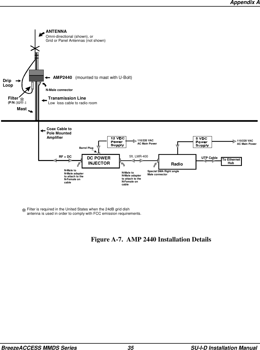
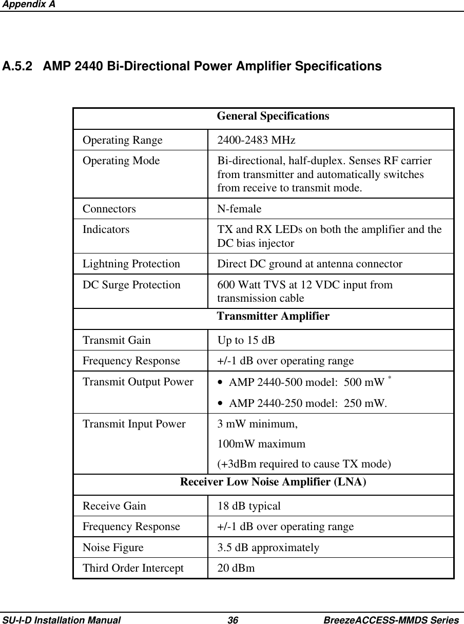
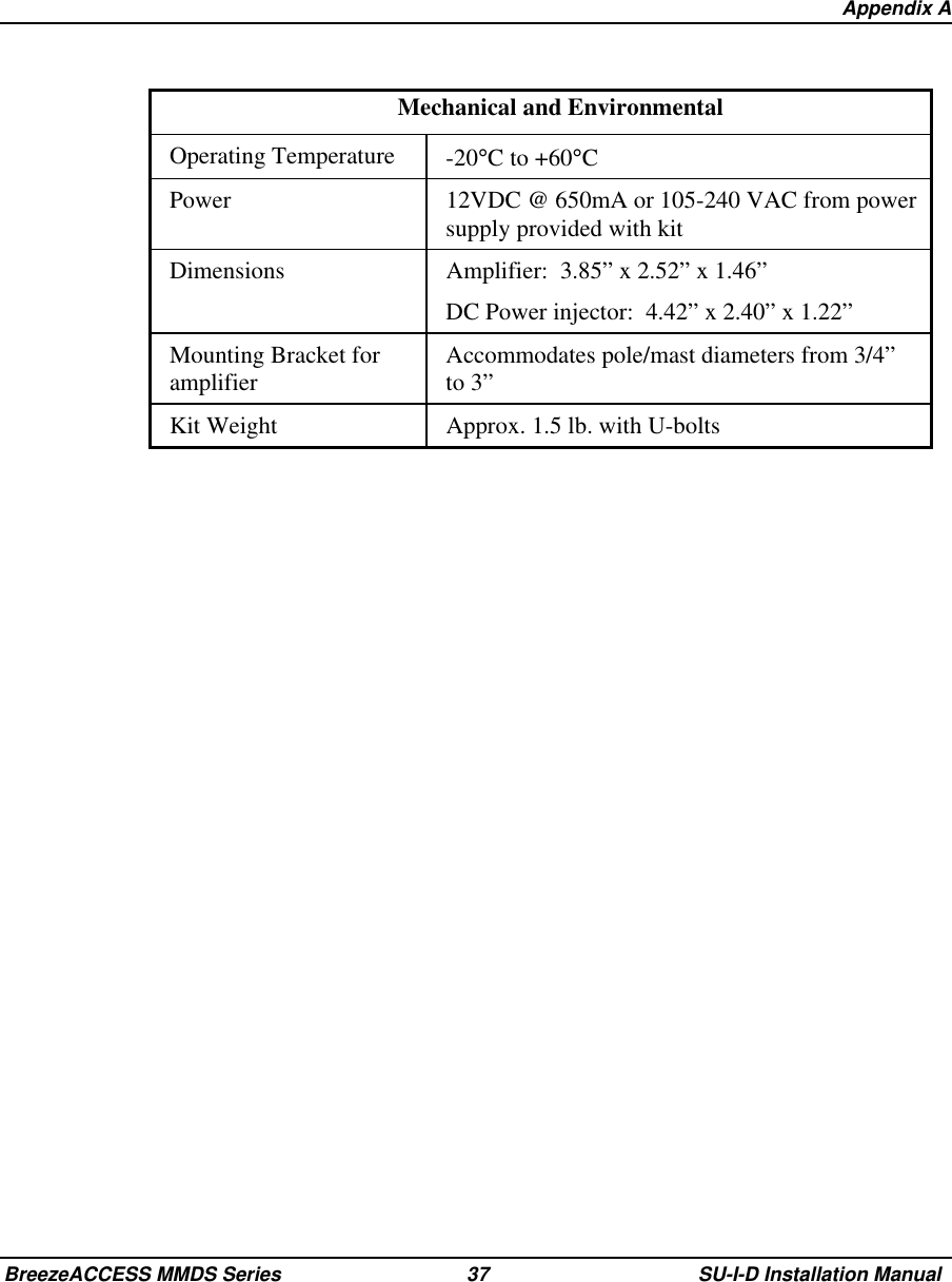
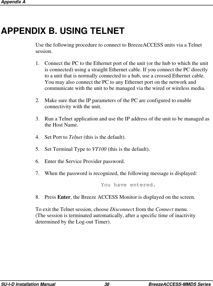
Alvarion Technologies SUI-MMDS1 Indoor MMDS CPE transceiver User Manual Indoor Subscriber unit radio

Alvarion Ltd. Indoor MMDS CPE transceiver Indoor Subscriber unit radio

Contents

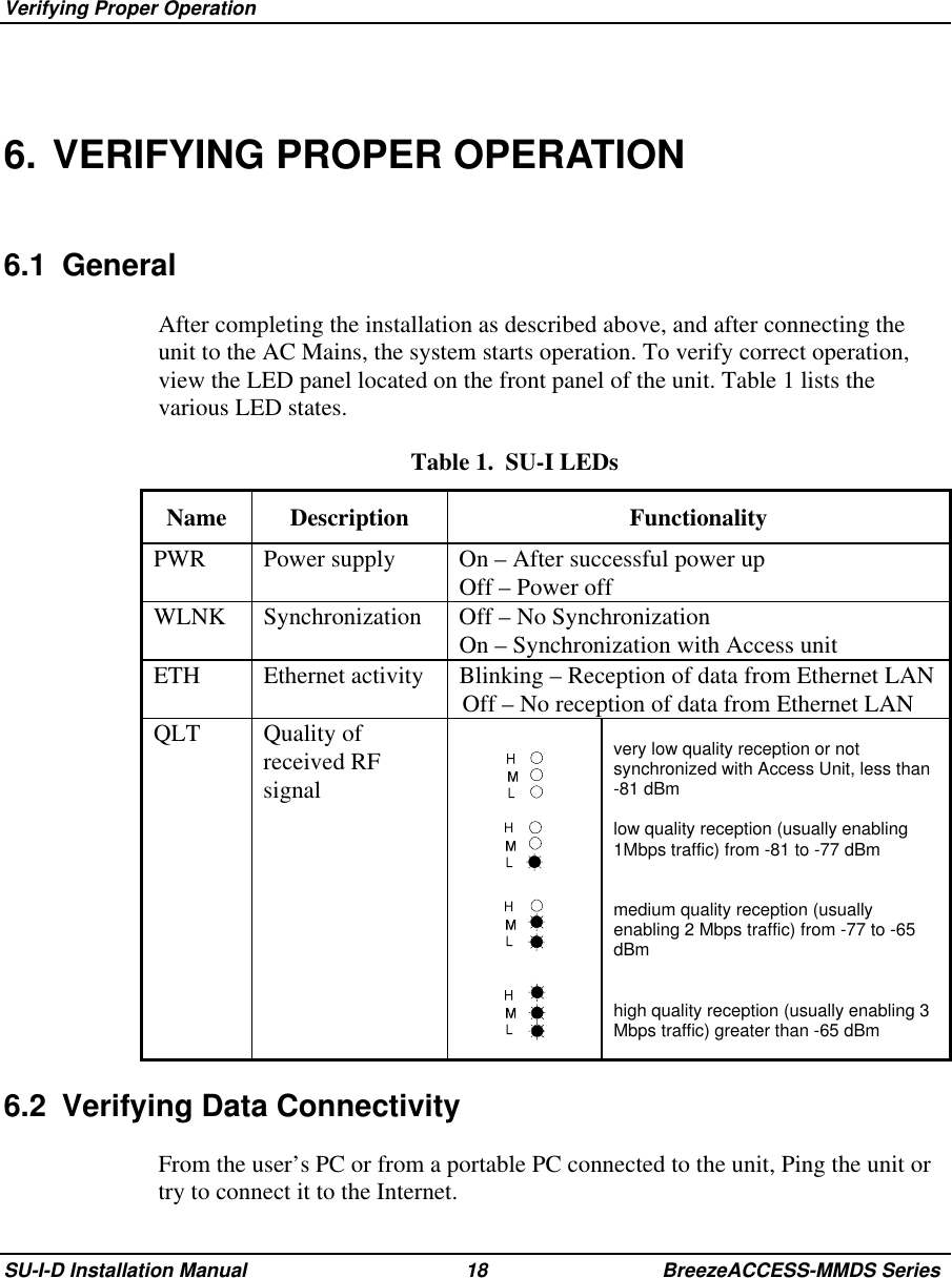
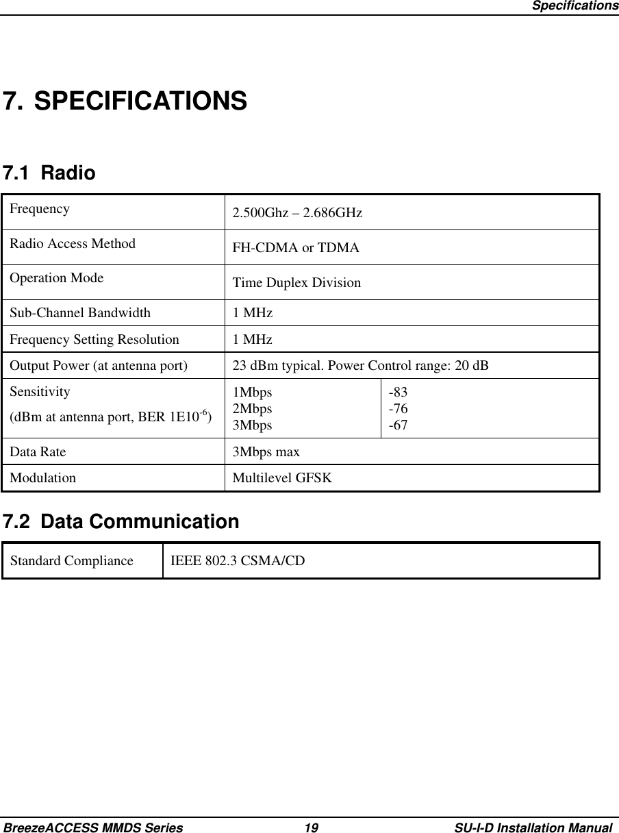
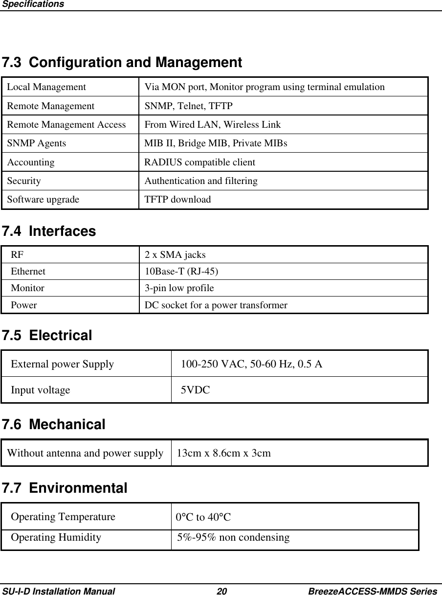
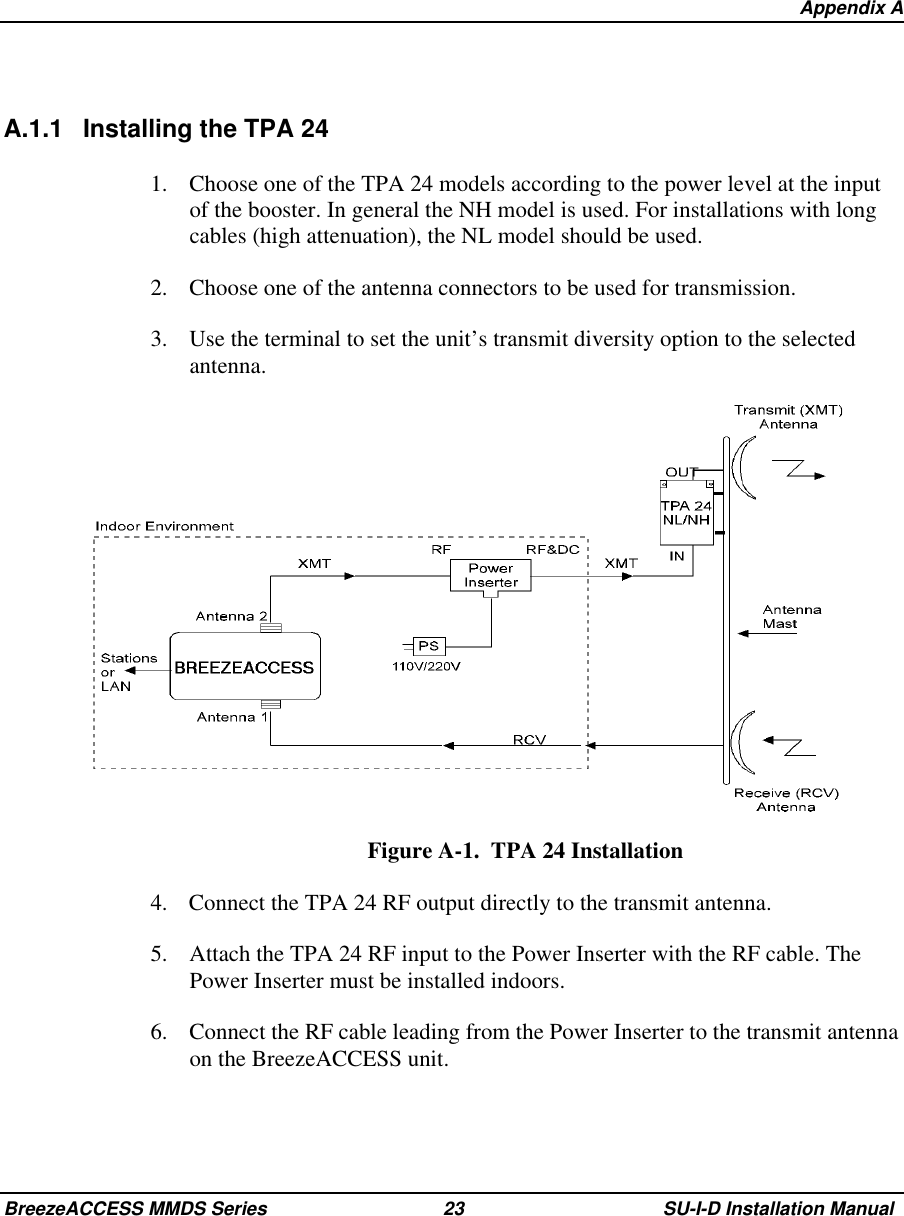
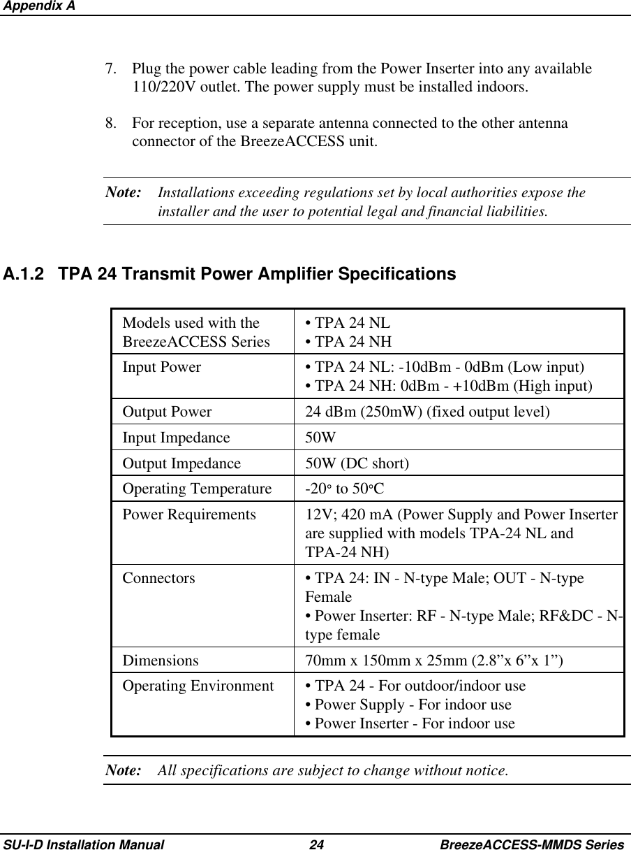
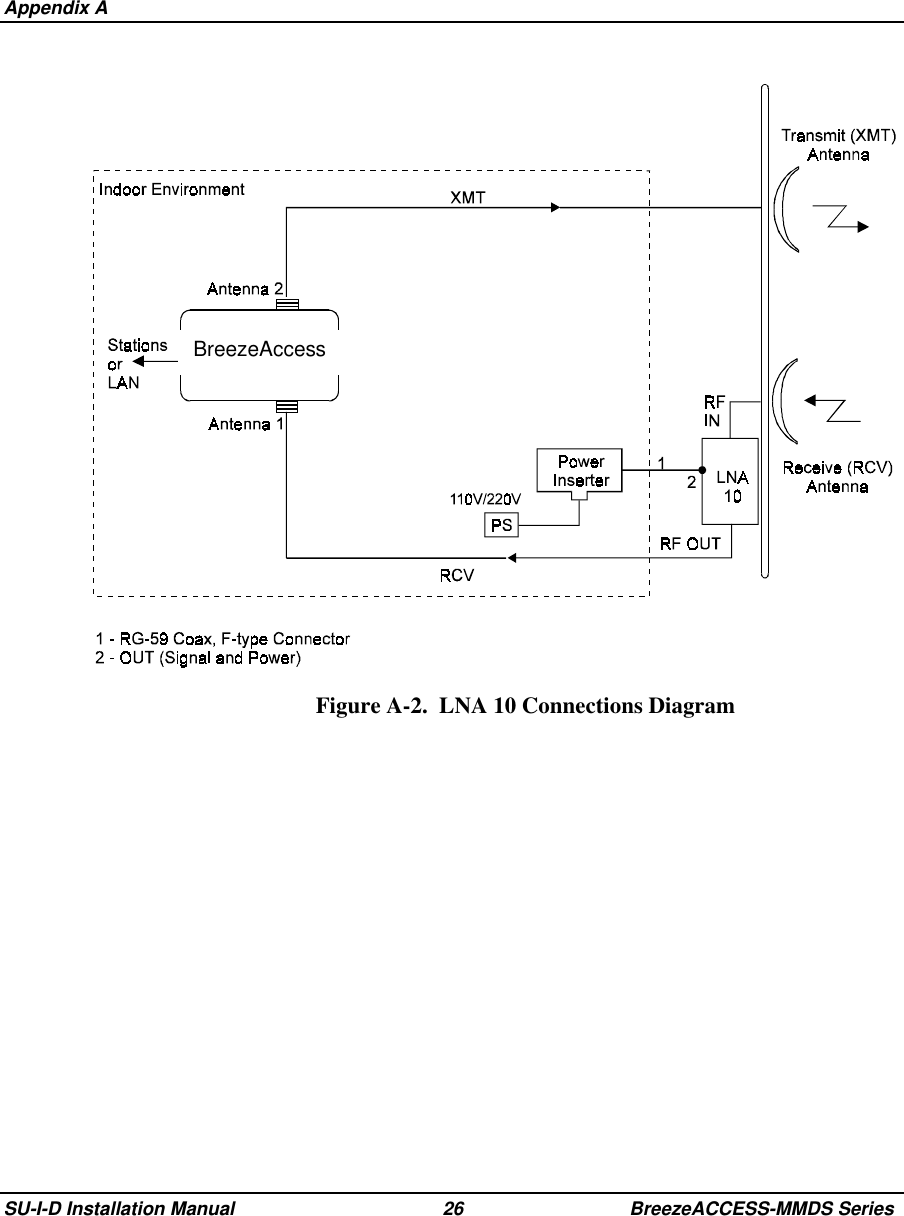
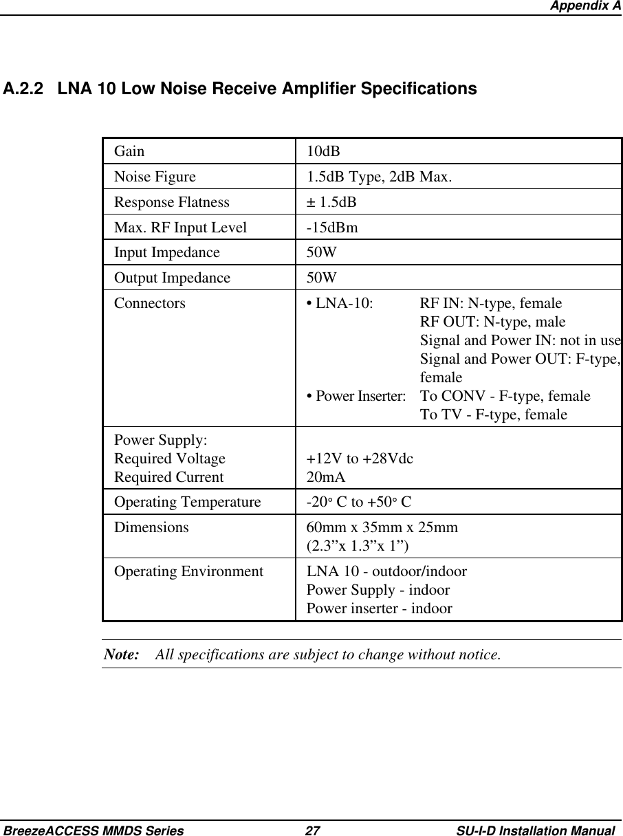
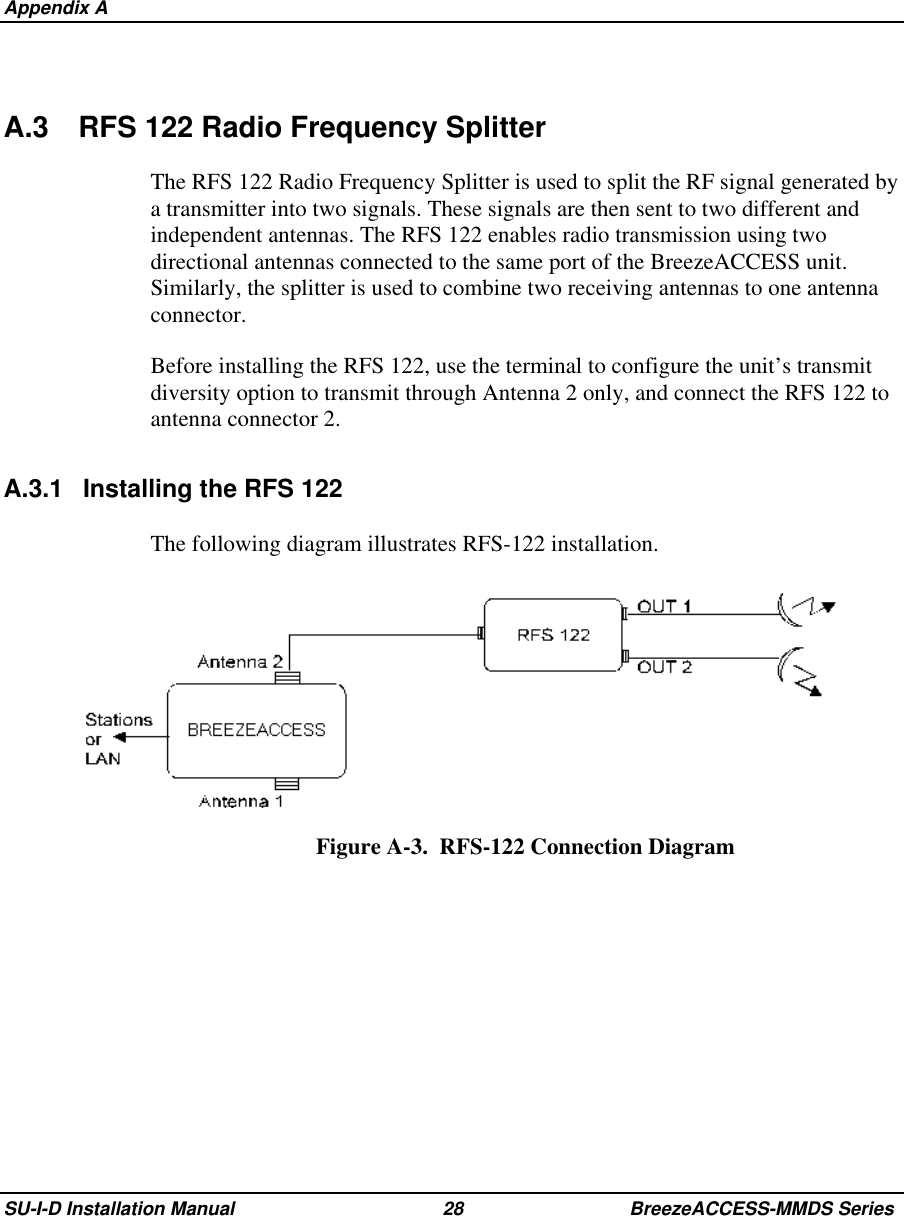
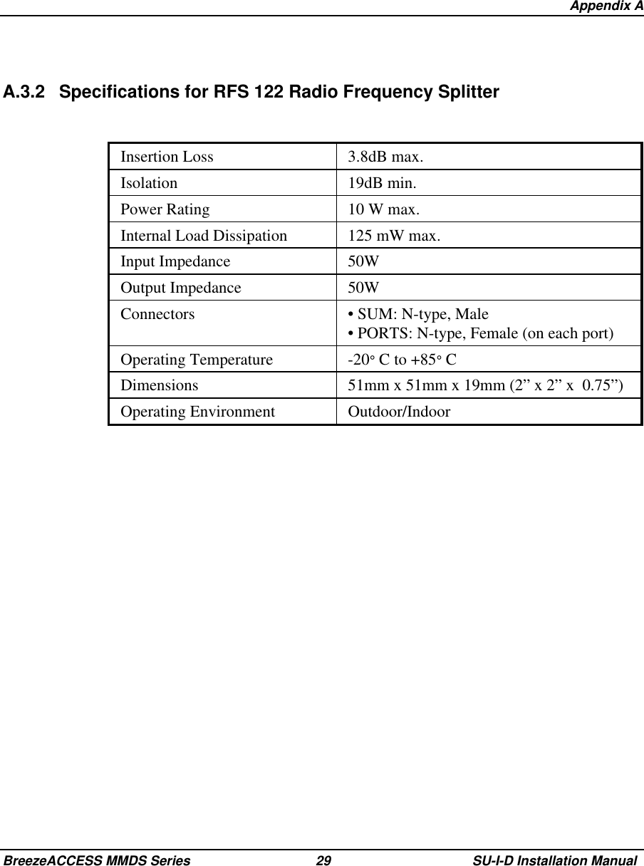
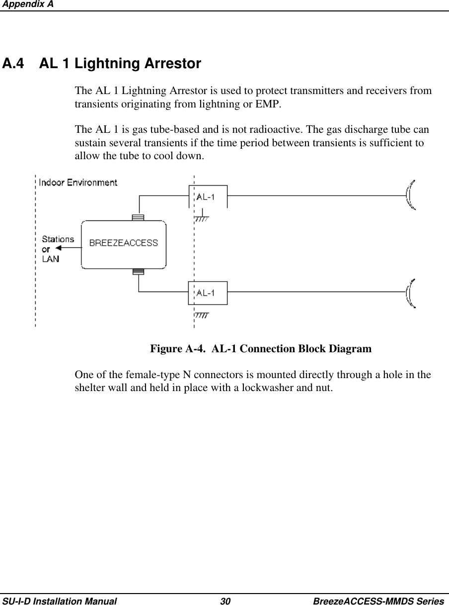
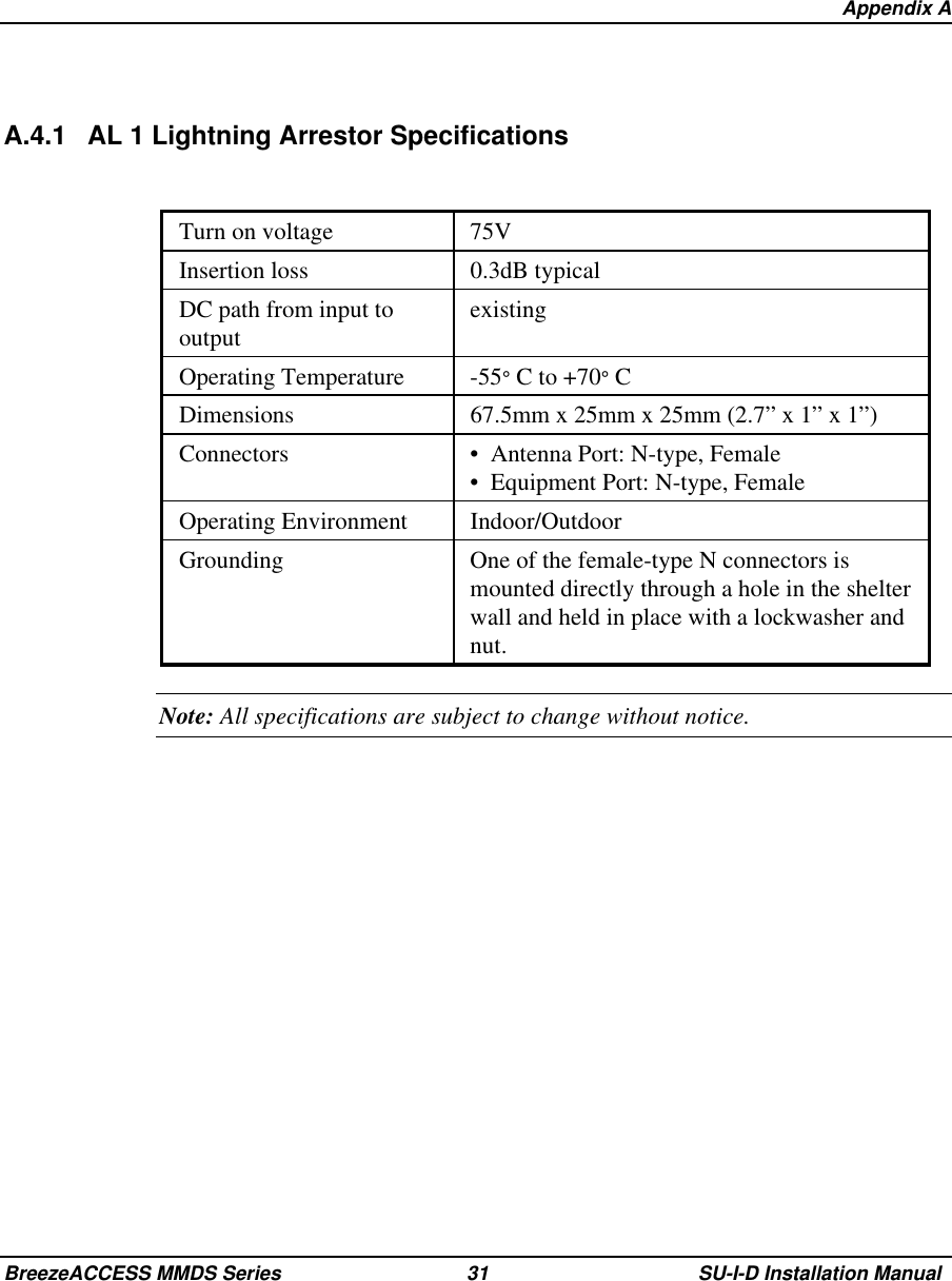
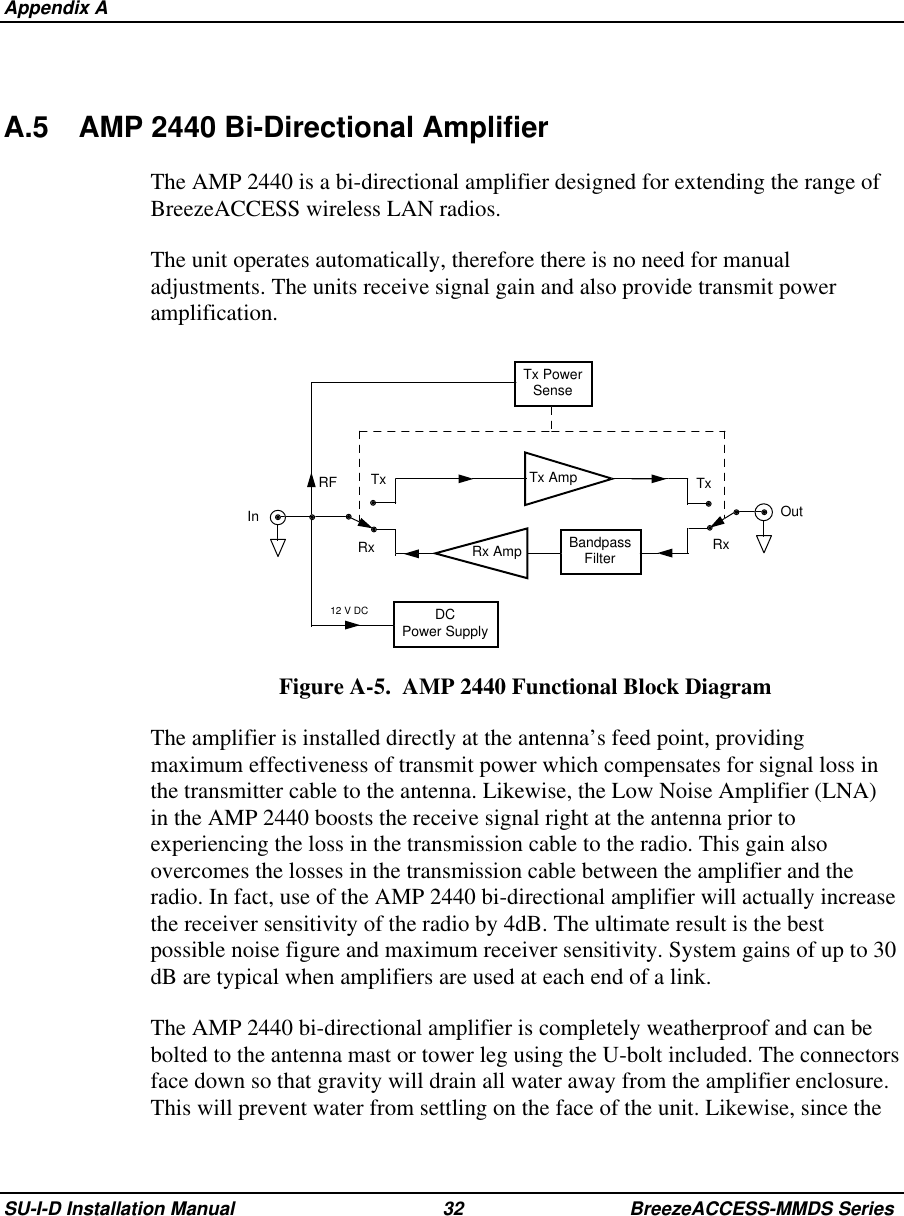
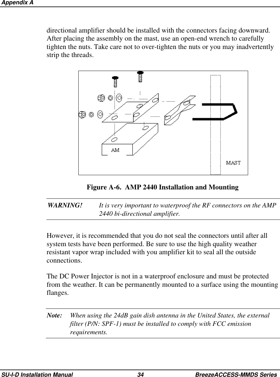
Indoor Subscriber unit radio user manual

BreezeACCESS MMDSIndoor Subscriber UnitsSU-I-D-MMDS SeriesInstallationManualJuly, 2000Cat. No. 213099
Front MatterSU-I-D Installation Manual ii BreezeACCESS-MMDS Series© 1999 by BreezeCOM Ltd. All rights reserved.No part of this publication may be reproduced in any material form without the written permission ofthe copyright owner.Trade NamesBreezeACCESS, BreezeNET, BreezeLINK, BreezeVIEW and WIX are trade names of BreezeCOMLtd. Other brand and product names are registered trademarks or trademarks of their respectivecompanies.Statement of ConditionsThe information contained in this manual is subject to change without notice. BreezeCOM shall not beliable for errors contained herein or for incidental or consequential damages in connection with thefurnishing, performance, or use of this manual or equipment supplied with it.WarrantyIn the following warranty text, “the Company” shall mean:•  BreezeCOM Ltd., for products located outside the USA.•  BreezeCOM Inc., for products located in the USA. This BreezeACCESS product is warranted against defects in material and workmanship for a periodof one year from date of purchase. During this warranty period the Company will, at its option, eitherrepair or replace products that prove to be defective. For warranty service or repair, the product must be returned to a service facility designated by theCompany. Authorization to return products must be obtained prior to shipment. The buyer shall payall shipping charges to the Company and the Company shall pay shipping charges to return theproduct to the buyer within the USA. The Company warrants that the firmware designed by it for use with the unit will execute itsprogramming instructions when properly installed on the unit. The Company does not warrant that theoperation of the unit or firmware will be uninterrupted or error-free.Limitation of WarrantyThe foregoing warranty shall not apply to defects resulting from improper or inadequate maintenanceby the buyer, buyer supplied interfacing, unauthorized modification or misuse, operation outside ofthe environmental specifications for the product, or improper site preparation or maintenance. Noother warranty is expressed or implied. The company specifically disclaims the implied warranties ofmerchantability and fitness for any particular purpose.
Front MatterBreezeACCESS MMDS Series iii SU-I-D Installation ManualBreezeCOM shall not be liable to any person for any special or indirect damages, including, but notlimited to, loss of profits or revenues, loss of use or damage to any associated equipment, cost ofcapital, cost of substitute products, facilities or services, downtime costs or claims resulting from anycause whatsoever arising from or in any way connected with the manufacture, sale, handling, service,repair, maintenance or use of the products. In no event shall the company’s liability exceed thepurchase price denoted on the invoice.Electronic Emission NoticeThis device complies with Part 15 of the FCC rules. Operation is subject to the following twoconditions:1.  This device may not cause harmful interference.2.  This device must accept any interference received, including interference that may causeundesired operation.FCC Radio Frequency Interference StatementThis equipment has been tested and found to comply with the limits for a class A digital device,pursuant to Part 15 of the FCC rules. These limits are designed to provide reasonable protectionagainst harmful interference when the equipment is operated in a commercial environment. Thisequipment generates, uses, and can radiate radio frequency energy and, if not installed and used inaccordance with the instruction manual, may cause harmful interference to radio communications.Operation of this equipment in a residential area is likely to cause harmful interference in which casethe user will be required to correct the interference at his own expense.Information to User Any changes or modifications of equipment not expressly approved by the manufacturer could voidthe user’s authority to operate the equipment.Safety Considerations For the following safety considerations, “Instrument” means the BreezeACCESS Subscriber orAccess unit components and their cables.Caution To avoid shock, do not perform any servicing unless you are qualified to do so.
Front MatterSU-I-D Installation Manual iv BreezeACCESS-MMDS Series Grounding Before connecting the instrument to the power line, verify that a suitable power cord is being used (theprotective earth terminal of this instrument must be connected to the protective conductor of the powercord). The mains plug shall only be inserted in a socket outlet provided with a protective earth contact. Ifan extension cord (power cable) is used make sure it has a protective conductor (grounding).Line Voltage Before connecting this instrument to the power line, make sure that the voltage of the power sourcematches the requirements of the instrument: 100-250 VAC, 50-60 Hz.RadioThe instrument transmits radio energy during normal operation. To avoid possible harmful exposureto this energy, do not stand or work for extended periods of time in front of its antenna. The long-termcharacteristics or the possible physiological effects of Radio Frequency Electromagnetic fields havenot been yet fully investigated.Antenna Installation and GroundingBe sure that the outdoor antennas and the supporting structure are properly installed to eliminate anyphysical hazard to either people or property. Verify that the antenna mast is grounded so as to provideprotection against voltage surges and static charges. Make sure that the installation of the antenna andcable is performed in accordance with all relevant national and local building and safety codes.
BreezeACCESS MMDS Series v SU-I-D Installation Manual Table of Contents1. INTRODUCTION ..................................................................................................................... 12. BASIC INSTALLATION .........................................................................................................22.1 Packing List ..........................................................................................................................22.2 Other Required Items............................................................................................................22.3 Installation Overview............................................................................................................32.4 Installation Guidelines ..........................................................................................................42.4.1 Location of the Unit and Antenna(s) .............................................................................42.4.2 Location of the Antenna(s) ............................................................................................42.4.3 Antenna Diversity..........................................................................................................52.4.4 Antenna Polarization......................................................................................................52.4.5 Antenna Seal..................................................................................................................52.4.6 Lightning Protection ......................................................................................................62.5 Wall Mounting the Unit........................................................................................................ 72.6 Connecting Antenna(s) to the Units...................................................................................... 82.7 Connecting the Unit to the Power Supply and to the CPE....................................................93. CONFIGURING SYSTEM PARAMETERS........................................................................ 103.1 Getting Started with the Local Terminal............................................................................. 103.2 Configuration Parameters ................................................................................................... 123.3 Reset Unit............................................................................................................................144. ALIGNING THE ANTENNA ................................................................................................154.1 Aligning the Antenna Using the LEDs ...............................................................................154.2 Aligning the Antenna Using the Site Survey Menu............................................................165. MAXIMUM DATA RATE CONFIGURATION..................................................................176. VERIFYING PROPER OPERATION..................................................................................18
Table of ContentsSU-I-D Installation Manual vi BreezeACCESS-MMDS Series6.1 General................................................................................................................................ 186.2 Verifying Data Connectivity...............................................................................................187. SPECIFICATIONS.................................................................................................................197.1 Radio...................................................................................................................................197.2 Data Communication ..........................................................................................................197.3 Configuration and Management.......................................................................................... 207.4 Interfaces.............................................................................................................................207.5 Electrical .............................................................................................................................207.6 Mechanical.......................................................................................................................... 207.7 Environmental.....................................................................................................................20APPENDIX A. OPTIONAL RF ACCESSORIES....................................................................22APPENDIX B. USING TELNET.............................................................................................39
  Table of ContentsBreezeACCESS MMDS Series vii SU-I-D Installation Manual Table of FiguresFigure 2-1.  Wall Mounting the Unit ..........................................................................................7Figure 2-2.  Wall Mounting Plate ............................................................................................... 8Figure 2-3. Tightening the Cable(s) to the Connector(s) ............................................................ 9Figure 3-1.  Main Menu............................................................................................................ 11Figure 3-2.  Basic Configuration Menu ....................................................................................13Table 1.  SU-I LEDs ................................................................................................................. 18Figure A-1.  TPA 24 Installation ..............................................................................................23Figure A-2.  LNA 10 Connections Diagram.............................................................................26Figure A-3.  RFS-122 Connection Diagram ............................................................................. 28Figure A-4.  AL-1 Connection Block Diagram ........................................................................30Figure A-5.  AMP 2440 Functional Block Diagram................................................................. 32Figure A-6.  AMP 2440 Installation and Mounting.................................................................. 34Figure A-7.  AMP 2440 Installation Details............................................................................. 36
BreezeACCESS MMDS Series 1 SU-I-D Installation Manual1. INTRODUCTIONThis manual describes installation guidelines for BreezeACCESS-MMDS SU-ISubscriber Units.The BreezeACCESS IP Broadband Wireless Local Loop (WLL) system allowsaccess service providers to provide high-speed IP connectivity services to theirsubscribers. To support IP-based services effectively BreezeACCESS systemsemploy wireless packet data switching technology.The BreezeACCESS 2.5 line of products uses Frequency Hopping SpreadSpectrum radios that operate in Time Duplex Division (TDD) mode in the2.500GHz – 2.686GHz frequency range.The SU-I-D-MMDS line of Subscriber Units comprises compact units that aredesigned for indoor installation. Antennas can be installed either indoors oroutdoors, depending on the specific site conditions. The SU-I-D-MMDS seriesinclude the following products:•  SU-I-1D-MMDS: supports a single Ethernet device•  SU-I-8D-MMDS: supports up to eight Ethernet workstations/PCs•  SU-I-BD-MMDS: supports a LAN (a bridge functionality)Note: The information contained in this manual is applicable to BreezeACCESSMMDS units with software release 2.3.
 Basic InstallationSU-I-D Installation Manual 2 BreezeACCESS-MMDS Series2. BASIC INSTALLATION2.1 Packing ListThe SU-I units are shipped with the following units and accessories. The exactpacking list varies depending on system configuration and ordered equipment.•  SU-I unit•  A 5 VDC universal power supply transformer•  Mounting bracket for wall or ceiling installation•  A torque key for antenna connectors2.2  Other Required ItemsThe following items must be available for the installation•  Antenna(s)*and RF cable(s)*(according to specific installationrequirements)*•  A PC with terminal emulation program•  A monitor cable* (supplied with each AU)•  An Ethernet cable (straight)•  Installation tools and materialsItems marked with an asterisk (*) are available from BreezeCOM.
  Basic InstallationBreezeACCESS MMDS Series 3 SU-I-D Installation Manual2.3 Installation OverviewStandard installation involves the following steps:1.  Verify that all components of the packing list, described in Section 2.1, areintact and verify availability of the required items listed in Section 2.2.2.  Install the unit and antenna(s) in optimal locations as described inSection 2.4.3.  Connect the antenna(s) to the unit as described in Section 2.6.4.  Connect the power supply to the unit as described in Section 2.7.5.  Connect the Ethernet port to the unit as described in Section 2.7.6.  Configure the basic system parameters as described in Section 3.7.  Align the antenna(s) for optimal connectivity and configure the MaximumData Rate if applicable, as described in Chapters 4 and 5.8.  Check the functionality of the unit as described in Chapter 6.Antennas for Indoor ApplicationsFor most indoor applications, the best choice is the standard unit equipped withits screw-on 2dBi antennas. The units are small, easy to install and cover a largearea.In some installations, it is required to install the unit and antenna separately. Insuch instances, use the omni-6 antenna kit (6dbi omni-directional antenna with 3meter RG-58 cable). In the USA (FCC regulated) and in non-regulated countries,the omni-6 comes with a shorter antenna cable, extending the coverage area.The Uni-8.5 is also useful in indoor applications. It is very small and easily wall-mounted, but its radiation pattern is limited (75°).BreezeCOM recommends that, for indoor applications, you use two antennas perunit to utilize the diversity gain of the system.
 Basic InstallationSU-I-D Installation Manual 4 BreezeACCESS-MMDS Series2.4 Installation GuidelinesThis section describes the installation guidelines and the various considerationsthat must be taken into account when planning the installation.2.4.1  Location of the Unit and Antenna(s)•  The unit can be placed on a shelf, or can be attached to the ceiling or a wallusing a mounting bracket. The unit should be installed as near to theantenna(s) as possible to minimize loss of RF power in the cable(s).•  Keep the units well away from sources of heat, such as radiators, air-conditioners, etc.2.4.2  Location of the Antenna(s)•  Any physical object in the path between two units can cause signalattenuation. Common obstructions are buildings and trees. If a unit’santenna is installed indoors, the walls and/or windows between the twosites are physical obstructions. If the antenna is positioned outdoors, anybuildings or other physical structure such as trees, mountains or othernatural geographic features higher than the antenna and situated in the pathbetween the two sites can constitute obstructions.•  Install indoor antennas as close as possible to a window (or wall if awindow is not accessible) facing the required direction. Avoid metalobstacles such as metal window frames or metal film anti-glare windows inthe transmission path. Install outdoor antennas high enough to avoid anyobstacles, which may block the signal.•  Position the antennas clear of metal furniture and away from moving metalobjects such as metal fans or doors.•  For best performance, position the antennas clear of radiation sources thatemit in the 2.5 - 2.7 GHz frequency band, such as microwave ovens.
  Basic InstallationBreezeACCESS MMDS Series 5 SU-I-D Installation Manual2.4.3 Antenna DiversityIn applications where no multipath propagation is expected, a single antenna issufficient to ensure good performance levels. However, in cases where multipathpropagation exists, BreezeCOM recommends that two antennas be used. Thistakes advantage of space diversity capabilities. By using two antennas per unit,the system can select the best antenna on a per-packet basis (every severalmilliseconds).Multipath propagation is to be expected when there are potential reflectorsbetween the Access Unit and Subscriber Units. These reflectors may be buildingsor moving objects such as airplanes and motor vehicles. If this is the case, theradio signal does not travel in a straight line, but is reflected or deflected off ofthe object, creating multiple propagation paths.When installing a single antenna, modify the transmit diversity option to eitherantenna 1 or antenna 2, according to the antenna being used.2.4.4 Antenna PolarizationAntenna polarization must be the same at either end of the link. In mostapplications, the preferred orientation is vertical polarization. Above-groundpropagation of the signal is better when it is polarized vertically. To verifyantenna polarization, refer to the assembly instructions supplied with the antennaset. For screw-on and detached omni antennas, make sure that the antennas areextended upward vertically in relation to the floor to achieve verticalpolarization.2.4.5 Antenna SealWhen using outdoor antennas, you must seal the antenna connectors against rain.Otherwise the antennas are not suitable for use in outdoor installations.2.4.6 Lightning ProtectionLightning protection is designed to protect people, property and equipment byproviding a path to ground for the lightning’s energy. The lightning arrestordiverts the strike energy to ground through a deliberate and controlled pathinstead of allowing it to choose a random path. Lightning protection for a
 Basic InstallationSU-I-D Installation Manual 6 BreezeACCESS-MMDS Seriesbuilding is more forgiving than protection of electronic devices. A building canwithstand up to 100,000 volts, but electronic equipment may be damaged by justa few volts.Lightning protection entails connecting an antenna discharge unit (also called anarrestor) to each cable as close as possible to the point where it enters thebuilding. It also entails proper grounding of the arrestors and of the antenna mast(if the antenna is connected to one).The lightning arrestor should be installed and grounded at the point where thecable enters the building. The arrestor is connected to the unit at one end and tothe antenna at the other end.The professional installer you choose must be knowledgeable about lightningprotection. The installer must install the lightning protector in a way thatmaximizes lightning protection. BreezeCOM offers the following high-qualitylightning arrestor assembly:BreezeACCESS AL 1 Lightning Arrestor - Part No. 872905 5 ft (1.5m), “N”Male to “N” Female.Note: Detached antennas, whether installed indoors or out, should be installedONLY by experienced antenna installation professionals who are familiarwith local building and safety codes and, wherever applicable, are licensedby the appropriate government regulatory authorities.Failure to do so may void the BreezeACCESS Product Warranty and mayexpose the end user to legal and financial liabilities. BreezeCOM and itsresellers or distributors are not liable for injury, damage or violation ofgovernment regulations associated with the installation of detachedantennas.
  Basic InstallationBreezeACCESS MMDS Series 7 SU-I-D Installation Manual2.5  Wall Mounting the UnitUse the supplied brackets for wall mounting to install the unit on a wall or aceiling.1.  Turn the unit so the rear panel is facing you.2.  Unscrew the two screws located at the antennas end of the unit (the topscrews).3.  Align the Unit Mounting Slots (see Figure 2-2) with the slots you have justunscrewed.4.  Using the longer screws supplied with the wall mounts, screw the wall mountto the unit.5.  Align the Convenience Mounting Slots (see Figure 2-2) with the nails, pushthe wall mount against the wall and let it slide down until it rests on the nails.Figure 2-1.  Wall Mounting the UnitSpecial slots have been added to the wall mounts to allow for unobtrusive cableinstallation. These slots should be used to fasten cables coming out of the unit tothe wall mounts, eliminating loose or tangled cable installations.
 Basic InstallationSU-I-D Installation Manual 8 BreezeACCESS-MMDS SeriesConvenience Mounting SlotsUnit Mounting SlotsCable Fastening SlotsFigure 2-2.  Wall Mounting Plate2.6  Connecting Antenna(s) to the UnitsFor installation convenience, a torque key is included with all BreezeACCESSSU-I units.WARNING: The use of improper tools for tightening antenna connection cablesto BreezeACCESS SU-I units may result in damage to the cableconnectors.Use the included torque key to tighten the cable(s) to the connector(s) on the sideof the SU-I unit. The key is designed to prevent over tightening of the screws andprotects the connectors from damage.Tighten the cable(s) to the connector(s) using the torque key.
  Basic InstallationBreezeACCESS MMDS Series 9 SU-I-D Installation ManualFigure 2-3. Tightening the Cable(s) to the Connector(s)If excessive pressure is applied to tighten the screws, the torque key will break.Note: Do not attempt to tighten the screws any further. This may damage theconnectors on the BreezeACCESS SU-I unit.2.7  Connecting the Unit to the Power Supply and to the CPEThe unit operates on a power input of 5V DC, supplied by the power transformerincluded with the unit.1.  Plug the output jack of the power transformer into the DC input jack locatedon the rear panel of the unit.2.  Connect the supplied universal power transformer to a power outlet - 110/220VAC.3.  Use a straight Ethernet 10BaseT cable to connect a PC (SU-I-1D) or a hub(SU-I-8D or SU-I-BD) to the Ethernet port (marked UTP) located on the rearpanel of the unit.
 Configuring System ParametersSU-I-D Installation Manual 10 BreezeACCESS-MMDS Series3. CONFIGURING SYSTEM PARAMETERSAfter completing the installation process, as described in the preceding sectionsof this manual, proceed with configuration of the basic system parameters.This manual covers the configuration of basic installation parameters. Refer tothe Administration Manual for information related to other parameters.Note: Optionally, the product can be configured using Telnet over the Ethernetport, after setting IP address. For further information refer to Appendix B.3.1  Getting Started with the Local Terminal1.  Connect one end of the Monitor cable to the MON jack on the rear side ofthe unit. Connect the second end of the cable to the COM port of theterminal. The COM port connector on the Monitor cable is a 9 pin D-typeplug.2.  Run a terminal emulation program (e.g., ProComm or WindowsHyperTerminal) using the following setup:Baud rate 9600Data bits 8Stop bits 1Parity NoneFlow Control Xon/XoffConnector Available Com Port3. Press Enter. The Select Access Level menu appears. Select the access levelaccording to your authorized access level. You will be requested to enteryour password. After entering the correct password press enter. The mainmenu appears (refer to Figure 3-1).
  Configuring System ParametersBreezeACCESS MMDS Series 11 SU-I-D Installation ManualSoftwareVersion No.BreezeACCESS (SU-1D)Official Release Version – 2.2.6Release Date:  Mon Apr 24 21:52:01 2000Main Menu=====================1 – Info Screens2 – Unit Control3 – Basic Configuration4 – Site Survey5 – Advanced ConfigurationBreezeACCESS >>>Figure 3-1.  Main Menu  The appearance of the displayed Main Menu varies in accordance with theaccess level.•  For users with read only access rights, only the Info Screens option isdisplayed. Users with this access level cannot access the Unit Control,Basic Configuration, Site Survey and Advanced Configuration menus.•  For users with Installer access rights, the first four menu items (InfoScreens, Unit Control, Basic Configuration and Site Survey) aredisplayed. Users with this access level cannot access the AdvancedConfiguration menu.•  For users with Administrator access rights, the full Main Menu will bedisplayed. These users can access all the menu items.4.  Operate the monitor program as follows:•  Type an option number to open/activate the option. You may needto press the Enter key in some cases.Unit TypeUnit Name
 Configuring System ParametersSU-I-D Installation Manual 12 BreezeACCESS-MMDS Series•  Press the Esc key to exit a menu or an option.•  You can log-out and exit the monitor program at any time bysimultaneously pressing the Ctrl and X keys.•  Reset the unit after making configuration changes for the new valuesto take effect.•  You can view the current parameters’ configuration by selecting 1 inthe Main Menu to Access the Info Screens menu, and than selecting2 in the Info Screens menu to view the Basic Configurationparameters.3.2 Configuration ParametersThe following system parameters must be configured for each specific installation:•  ESSID•  IP Address•  Subnet Mask•  Default Gateway Address•  Hopping Shift (AU-I only)•  Hopping Set (AU-I only)•  Transmit Antenna•  Maximum Data RateNote: You must select Reset Unit in the Unit Control menu for the changes to takeeffect.Subscriber Units should be configured after the applicable Access Unit isoperational. When configuring Subscriber Units, the first parameter that shouldbe configured is the ESSID. Otherwise the unit will not successfully synchronizewith the Access Unit and will continuously reset itself, thus interfering with theconfiguration process.
  Configuring System ParametersBreezeACCESS MMDS Series 13 SU-I-D Installation Manual1. From the main menu, type 3 to access the Basic Configuration menu.BreezeACCESS (AU-I)Official Release Version – 2.2.6Release Date:  Mon Apr 24 21:52:01 2000Basic Configuration====================1 – IP Address2 – Subnet Mask3 – Default Gateway Address4 – ESSID5 – Maximum Data Rate6 - Frequency Offset7 – Hopping Shift8 – Hopping Sync9 - Hopping SetA - Power LevelG – Transmit AntennaS - Show Basic ConfigurationBreezeACCESS >>>Figure 3-2.  Basic Configuration Menu2. From the Basic Configuration menu, type 4 to access the ESSID selectionscreen. Enter the required ESSID.3. Type 1 to access the IP Address selection screen. Enter the required IPaddress.4. Type 2 to access the Subnet Mask selection screen. Enter the required subnetmask.5. Type 3 to access the Default Gateway Address selection screen. Enter therequired default gateway address.6. Type 7 to access the Hopping Shift selection screen. Enter the requiredHopping Shift (AU-I units only).
 Configuring System ParametersSU-I-D Installation Manual 14 BreezeACCESS-MMDS Series7. Type 9 to access the Hopping Set selection screen. Enter the requiredhopping set (AU-I units only).8. Type G to access the Transmit Antenna selection screen. Enter the requiredselection (0 - use two antennas, 1 - use antenna #1, 2 - use antenna #2).3.3 Reset Unit1. From the main menu, type 2 to access the Unit Control menu.2. Type 1 to access the Reset Unit menu. Type 1 to reset the unit so that newconfiguration settings are applied.Note: Should you make any mistakes during configuration or encounter anyproblems associated with system configuration parameters, you mayconfigure the unit back to the factory defaults, as follows:Type 2 in the Unit Control menu to access the Set Factory Defaults menu.Type in 2 (Set Factory defaults-Full) to load the default values. Reset theunit for the factory defaults values to take effect.
 Aligning the AntennaBreezeACCESS MMDS Series 15 SU-I-D Installation Manual4. ALIGNING THE ANTENNAOmni and low gain antennas do not require alignment due to their wide radiationpattern. High gain antennas have a narrow beamwidth, necessitating an alignmentprocedure in order to optimize the link.For Subscriber Units with directional antenna(s), you can either use the LEDindicators on the front panel of the unit or view the Received Signal StrengthIndication (RSSI) on the monitor. In most installations, alignment using theLEDs is sufficient. The RSSI reading can be used when finer alignment isrequired.Note: Antenna alignment of the Subscriber Unit is possible only after the AccessUnit you wish to associate with is operational and the ESSID was properlyconfigured.4.1  Aligning the Antenna Using the LEDs1.  Synchronize the units by aligning the antenna manually to point to the basestation until the WLNK indicator LED on the front panel of the unitilluminates.2.  Rotate the antenna left and/or right until you reach the point of signal qualityreading on the quality (QLT) LEDs. The higher the number of illuminatedLEDs the better is the quality of the link. Make sure that at all times, thefront of the antenna faces the general direction of the Access Unit.3.  For proper operation, at least one (L) LED should be illuminated. If this isnot possible, improve the link quality by placing the antenna at a higherpoint or in a different location.4.  After the antenna is optimally aligned, tighten the U-bolts (or metal band) tosecure the antenna to the pole.
 Aligning the AntennaSU-I-D Installation Manual 16 BreezeACCESS-MMDS Series4.2  Aligning the Antenna Using the Site Survey Menu1.  Start the Monitor program as described in Section 3.1.2. From the main menu, type 4 to access the Site Survey menu. Type 4 to startthe Continuous RSSI Display. Each line in the display includes the number offrames that were received since the last measurement (total Rx) and theaverage RSSI for these frames.3.  Rotate the antenna left and/or right until you reach the point of maximumRSSI reading. Make sure that at all times, the front of the antenna faces thegeneral direction of the Base Station.4.  For proper operation, the RSSI reading should be at least 52 units. When themaximum reading is less than 52 units, try to improve it by placing theantenna at a higher point or in a different location. For best performance it isrecommended that the RSSI be higher than 76.5. Press the Esc key to stop the test.6.  Tighten the U-bolts (or metal band) over the antenna to secure it to the pole.
  Maximum Data Rate ConfigurationBreezeACCESS MMDS Series 17 SU-I-D Installation Manual5. MAXIMUM DATA RATE CONFIGURATION1.  If the average RSSI reading using the Average RSSI Continuous Display islower than 76, the default data rate of 3 Mbps is too high and the data rate ofthe unit should be configured accordingly:2. From the main menu, type 3 to access the Basic Configuration menu. Type 5to access the Maximum Data Rate menu.i)  Type 3 (3Mbps) if the RSSI reading is higher than 76 units.ii)  Type 2 (2Mbps) if the RSSI reading is between 66 to 76 units.iii)  Type 1 (1Mbps) if the RSSI reading is lower than 66 units.3.  Reset the unit for the new configuration to become effective.
 Verifying Proper OperationSU-I-D Installation Manual 18 BreezeACCESS-MMDS Series6. VERIFYING PROPER OPERATION6.1 GeneralAfter completing the installation as described above, and after connecting theunit to the AC Mains, the system starts operation. To verify correct operation,view the LED panel located on the front panel of the unit. Table 1 lists thevarious LED states.Table 1.  SU-I LEDsName Description FunctionalityPWR Power supply On – After successful power upOff – Power offWLNK Synchronization Off – No SynchronizationOn – Synchronization with Access unitETH Ethernet activity Blinking – Reception of data from Ethernet LANOff – No reception of data from Ethernet LANQLT Quality ofreceived RFsignalvery low quality reception or notsynchronized with Access Unit, less than-81 dBmlow quality reception (usually enabling1Mbps traffic) from -81 to -77 dBmmedium quality reception (usuallyenabling 2 Mbps traffic) from -77 to -65dBmhigh quality reception (usually enabling 3Mbps traffic) greater than -65 dBm6.2  Verifying Data ConnectivityFrom the user’s PC or from a portable PC connected to the unit, Ping the unit ortry to connect it to the Internet.
  SpecificationsBreezeACCESS MMDS Series 19 SU-I-D Installation Manual7. SPECIFICATIONS7.1 RadioFrequency 2.500Ghz – 2.686GHzRadio Access Method FH-CDMA or TDMAOperation Mode Time Duplex DivisionSub-Channel Bandwidth 1 MHzFrequency Setting Resolution 1 MHzOutput Power (at antenna port) 23 dBm typical. Power Control range: 20 dBSensitivity(dBm at antenna port, BER 1E10-6)1Mbps2Mbps3Mbps-83-76-67Data Rate 3Mbps maxModulation Multilevel GFSK7.2 Data CommunicationStandard Compliance IEEE 802.3 CSMA/CD
 SpecificationsSU-I-D Installation Manual 20 BreezeACCESS-MMDS Series7.3  Configuration and ManagementLocal Management Via MON port, Monitor program using terminal emulationRemote Management SNMP, Telnet, TFTPRemote Management Access From Wired LAN, Wireless LinkSNMP Agents MIB II, Bridge MIB, Private MIBsAccounting RADIUS compatible clientSecurity Authentication and filteringSoftware upgrade TFTP download7.4 InterfacesRF 2 x SMA jacksEthernet 10Base-T (RJ-45)Monitor 3-pin low profilePower DC socket for a power transformer7.5 ElectricalExternal power Supply 100-250 VAC, 50-60 Hz, 0.5 AInput voltage 5VDC7.6 MechanicalWithout antenna and power supply 13cm x 8.6cm x 3cm7.7 EnvironmentalOperating Temperature 0°C to 40°COperating Humidity 5%-95% non condensing
  SpecificationsBreezeACCESS MMDS Series 21 SU-I-D Installation Manual
 Appendix ASU-I-D Installation Manual 22 BreezeACCESS-MMDS SeriesAPPENDIX A. OPTIONAL RF ACCESSORIESThis appendix introduces some of the accessories available for specificinstallations, and describes how to install them.A.1 TPA 24 Transmit Power Amplifier (Booster)The TPA 24 Transmit Power Amplifier is used to amplify the transmit power to afixed output of 24 dBm (250 mW). The TPA 24 is especially useful when longRF cable runs are required. In addition, the TPA 24 simplifies antenna alignmentby enabling the use of wider dispersion transmit antennas. The TPA 24 isinternally protected against lightning and voltage surge protection.The TPA 24 comes in two models:•  The TPA 24 NL receives input power in the range of -10dBm to 0dBm.•  The TPA 24 NH receives an input power of 0dBm to +10dBm.Both models amplify the input power to a fixed output level of 24dBm (250mW).The TPA is powered by 12VDC carried from the power inserter by the RF cable.Note: The TPA 24 is not available in the USA due to FCC regulations.When used in compliance with ETSI regulations, the TPA 24 can be connected tocables and antennas resulting in a total transmitted power of 20dBm (100 mW) EIRP.
  Appendix ABreezeACCESS MMDS Series 23 SU-I-D Installation ManualA.1.1 Installing the TPA 241.  Choose one of the TPA 24 models according to the power level at the inputof the booster. In general the NH model is used. For installations with longcables (high attenuation), the NL model should be used.2.  Choose one of the antenna connectors to be used for transmission.3.  Use the terminal to set the unit’s transmit diversity option to the selectedantenna.Figure A-1.  TPA 24 Installation4.  Connect the TPA 24 RF output directly to the transmit antenna.5.  Attach the TPA 24 RF input to the Power Inserter with the RF cable. ThePower Inserter must be installed indoors.6.  Connect the RF cable leading from the Power Inserter to the transmit antennaon the BreezeACCESS unit.
 Appendix ASU-I-D Installation Manual 24 BreezeACCESS-MMDS Series7.  Plug the power cable leading from the Power Inserter into any available110/220V outlet. The power supply must be installed indoors.8.  For reception, use a separate antenna connected to the other antennaconnector of the BreezeACCESS unit.Note: Installations exceeding regulations set by local authorities expose theinstaller and the user to potential legal and financial liabilities.A.1.2 TPA 24 Transmit Power Amplifier SpecificationsModels used with theBreezeACCESS Series • TPA 24 NL• TPA 24 NHInput Power • TPA 24 NL: -10dBm - 0dBm (Low input)• TPA 24 NH: 0dBm - +10dBm (High input)Output Power 24 dBm (250mW) (fixed output level)Input Impedance 50WOutput Impedance 50W (DC short)Operating Temperature -20° to 50°CPower Requirements 12V; 420 mA (Power Supply and Power Inserterare supplied with models TPA-24 NL andTPA-24 NH)Connectors • TPA 24: IN - N-type Male; OUT - N-typeFemale• Power Inserter: RF - N-type Male; RF&DC - N-type femaleDimensions 70mm x 150mm x 25mm (2.8”x 6”x 1”)Operating Environment • TPA 24 - For outdoor/indoor use• Power Supply - For indoor use• Power Inserter - For indoor useNote: All specifications are subject to change without notice.
  Appendix ABreezeACCESS MMDS Series 25 SU-I-D Installation ManualA.2 LNA 10 Low Noise Receive AmplifierThe LNA 10 is a high-performance, low-noise preamplifier designed to enhancefringe area reception and provide additional gain on the receive antenna. Itsexceptionally small size and light weight enables it to be directly mounted on theantenna by means of the female RF IN connector. Power is obtained through anRG-59 coaxial cable connected to the power supply. The LNA 10 is internallyprotected against lightning and voltage surge protection.The Power Supply (PS) and Power Inserter are supplied with the LNA 10.The RG-59 coaxial cable with F-type connector is not supplied and must bepurchased separately.A.2.1 Installing the LNA 10Before installing the LNA 10, the following steps must be taken:1.  Choose one of the antenna connectors to be used for reception. Thisconnector is called the receive antenna of the unit. The other connector iscalled the transmit antenna of the unit.2.  Use the terminal to set the unit’s transmit diversity option to the selectedantenna (see Section). This prevents transmission from going through theLNA 10.3.  Connect the LNA 10 RF input directly and as close as possible to the receiveantenna.4.  Attach the LNA 10 RF output directly to the RF cable going down to thereceive antenna connector on the BreezeACCESS unit.5.  Connect the RG-59 coaxial cable which leads down to the Power Inserter tothe Signal and Power out connector on the LNA 10.6.  Connect the Power Inserter to the power supply (both are indoor units).7.  For transmission, use a separate antenna connected to the other antennaconnector (transmit antenna) of the BreezeACCESS unit.
 Appendix ASU-I-D Installation Manual 26 BreezeACCESS-MMDS SeriesBreezeAccessFigure A-2.  LNA 10 Connections Diagram
  Appendix ABreezeACCESS MMDS Series 27 SU-I-D Installation ManualA.2.2 LNA 10 Low Noise Receive Amplifier SpecificationsGain 10dBNoise Figure 1.5dB Type, 2dB Max.Response Flatness ± 1.5dBMax. RF Input Level -15dBmInput Impedance 50WOutput Impedance 50WConnectors • LNA-10: RF IN: N-type, femaleRF OUT: N-type, maleSignal and Power IN: not in useSignal and Power OUT: F-type,female• Power Inserter: To CONV - F-type, femaleTo TV - F-type, femalePower Supply:Required VoltageRequired Current +12V to +28Vdc20mAOperating Temperature -20° C to +50° CDimensions 60mm x 35mm x 25mm(2.3”x 1.3”x 1”)Operating Environment LNA 10 - outdoor/indoorPower Supply - indoorPower inserter - indoorNote: All specifications are subject to change without notice.
 Appendix ASU-I-D Installation Manual 28 BreezeACCESS-MMDS SeriesA.3 RFS 122 Radio Frequency SplitterThe RFS 122 Radio Frequency Splitter is used to split the RF signal generated bya transmitter into two signals. These signals are then sent to two different andindependent antennas. The RFS 122 enables radio transmission using twodirectional antennas connected to the same port of the BreezeACCESS unit.Similarly, the splitter is used to combine two receiving antennas to one antennaconnector.Before installing the RFS 122, use the terminal to configure the unit’s transmitdiversity option to transmit through Antenna 2 only, and connect the RFS 122 toantenna connector 2.A.3.1 Installing the RFS 122The following diagram illustrates RFS-122 installation.Figure A-3.  RFS-122 Connection Diagram
  Appendix ABreezeACCESS MMDS Series 29 SU-I-D Installation ManualA.3.2 Specifications for RFS 122 Radio Frequency SplitterInsertion Loss 3.8dB max.Isolation 19dB min.Power Rating 10 W max.Internal Load Dissipation 125 mW max.Input Impedance 50WOutput Impedance 50WConnectors • SUM: N-type, Male• PORTS: N-type, Female (on each port)Operating Temperature -20° C to +85° CDimensions 51mm x 51mm x 19mm (2” x 2” x  0.75”)Operating Environment Outdoor/Indoor
 Appendix ASU-I-D Installation Manual 30 BreezeACCESS-MMDS SeriesA.4 AL 1 Lightning ArrestorThe AL 1 Lightning Arrestor is used to protect transmitters and receivers fromtransients originating from lightning or EMP.The AL 1 is gas tube-based and is not radioactive. The gas discharge tube cansustain several transients if the time period between transients is sufficient toallow the tube to cool down.Figure A-4.  AL-1 Connection Block DiagramOne of the female-type N connectors is mounted directly through a hole in theshelter wall and held in place with a lockwasher and nut.
  Appendix ABreezeACCESS MMDS Series 31 SU-I-D Installation ManualA.4.1 AL 1 Lightning Arrestor SpecificationsTurn on voltage 75VInsertion loss 0.3dB typicalDC path from input tooutput existingOperating Temperature -55° C to +70° CDimensions 67.5mm x 25mm x 25mm (2.7” x 1” x 1”)Connectors •  Antenna Port: N-type, Female•  Equipment Port: N-type, FemaleOperating Environment Indoor/OutdoorGrounding One of the female-type N connectors ismounted directly through a hole in the shelterwall and held in place with a lockwasher andnut.Note: All specifications are subject to change without notice.
 Appendix ASU-I-D Installation Manual 32 BreezeACCESS-MMDS SeriesA.5 AMP 2440 Bi-Directional AmplifierThe AMP 2440 is a bi-directional amplifier designed for extending the range ofBreezeACCESS wireless LAN radios.The unit operates automatically, therefore there is no need for manualadjustments. The units receive signal gain and also provide transmit poweramplification.Tx PowerSenseInDCPower Supply12 V DCRxTx Tx AmpRx Amp BandpassFilterTxOutRFRxFigure A-5.  AMP 2440 Functional Block DiagramThe amplifier is installed directly at the antenna’s feed point, providingmaximum effectiveness of transmit power which compensates for signal loss inthe transmitter cable to the antenna. Likewise, the Low Noise Amplifier (LNA)in the AMP 2440 boosts the receive signal right at the antenna prior toexperiencing the loss in the transmission cable to the radio. This gain alsoovercomes the losses in the transmission cable between the amplifier and theradio. In fact, use of the AMP 2440 bi-directional amplifier will actually increasethe receiver sensitivity of the radio by 4dB. The ultimate result is the bestpossible noise figure and maximum receiver sensitivity. System gains of up to 30dB are typical when amplifiers are used at each end of a link.The AMP 2440 bi-directional amplifier is completely weatherproof and can bebolted to the antenna mast or tower leg using the U-bolt included. The connectorsface down so that gravity will drain all water away from the amplifier enclosure.This will prevent water from settling on the face of the unit. Likewise, since the
  Appendix ABreezeACCESS MMDS Series 33 SU-I-D Installation ManualLEDs are also facing downward they can be checked for operation from thebottom of the mast.DC Power to the amplifier is supplied through the transmission cable, using anindoor power supply and DC Injector. The amplifier unit also contains its ownintegral lightning protection and DC surge protection to ensure years ofcontinuous outdoor operation.BreezeCOM provides the user with two models of the AMP 2440 bi-directionalamplifier:•  AMP 2440-500. Provides 500 mW (+27dBm) maximum output•  AMP 2440-250. Provides 250 mW (+24dBm) maximum outputThe transmit gain for both models is 12 - 15dB. Full output power ofapproximately 500 mW is achieved with 30 mW (+15 dBm) input to theamplifier; 8 mW (+9dBm) for the AMP 2440-250 model. The amplifier goes intolimiting at this point and higher input power results in only slight increases in theoutput power. Up to 100 mW of power may be safely applied directly to theamplifier input without any damage on either model.The AMP 2440 bi-directional amplifier comes with power supplies that havestandard 2.1 mm barrel plugs (which are configured as positive (+) tip andnegative (-) outer conductor). Although normally supplied with a power supply,any regulated 12 Volt DC 1 amp supply can be used. The power supply can beused with 110 or 240 VAC power.A.5.1 Installing the AMP 2440 Bi-Directional AmplifierThe AMP 2440 bi-directional amplifier is designated for installation byprofessional radio installers. Several key factors unique to the particularinstallation determine the power level at the input of the amplifier. The mostimportant consideration is the cable loss in the transmission cable between theradio and the pole mounted amp. The installer should understand these and otherfactors when computing the input power to the amplifier.The AMP 2440 bi-directional amplifier can be mast mounted using the steel U-bolt included with the unit, as shown in Figure A-7. The AMP 2440 bi-
 Appendix ASU-I-D Installation Manual 34 BreezeACCESS-MMDS Seriesdirectional amplifier should be installed with the connectors facing downward.After placing the assembly on the mast, use an open-end wrench to carefullytighten the nuts. Take care not to over-tighten the nuts or you may inadvertentlystrip the threads.Figure A-6.  AMP 2440 Installation and MountingWARNING! It is very important to waterproof the RF connectors on the AMP2440 bi-directional amplifier.However, it is recommended that you do not seal the connectors until after allsystem tests have been performed. Be sure to use the high quality weatherresistant vapor wrap included with you amplifier kit to seal all the outsideconnections.The DC Power Injector is not in a waterproof enclosure and must be protectedfrom the weather. It can be permanently mounted to a surface using the mountingflanges.Note: When using the 24dB gain dish antenna in the United States, the externalfilter (P/N: SPF-1) must be installed to comply with FCC emissionrequirements.
  Appendix ABreezeACCESS MMDS Series 35 SU-I-D Installation ManualDC POWERINJECTOR Radio To EthernetHubUTP Cable5ft. LMR-400RF + DCN-Male toN-Male adapterto attach to theN-Female oncableSpecial SMA Right angleMale connectorANTENNAOmni-directional (shown), orGrid or Panel Antennas (not shown)AMP2440 (mounted to mast with U-Bolt)N-Male connectorTransmission LineLow  loss cable to radio roomMastDripLoopFilter(P/N: )SPF-1Coax Cable toPole MountedAmplifierBarrel Plug110/220 VACAC Main Power 110/220 VACAC Main Power**Filter is required in the United States when the 24dB grid dishantenna is used in order to comply with FCC emission requirements.N-Male toN-Male adapterto attach to theN-Female oncableFigure A-7.  AMP 2440 Installation Details
 Appendix ASU-I-D Installation Manual 36 BreezeACCESS-MMDS SeriesA.5.2 AMP 2440 Bi-Directional Power Amplifier SpecificationsGeneral SpecificationsOperating Range 2400-2483 MHzOperating Mode Bi-directional, half-duplex. Senses RF carrierfrom transmitter and automatically switchesfrom receive to transmit mode.Connectors N-femaleIndicators TX and RX LEDs on both the amplifier and theDC bias injectorLightning Protection Direct DC ground at antenna connectorDC Surge Protection 600 Watt TVS at 12 VDC input fromtransmission cableTransmitter AmplifierTransmit Gain Up to 15 dBFrequency Response +/-1 dB over operating rangeTransmit Output Power •  AMP 2440-500 model:  500 mW *•  AMP 2440-250 model:  250 mW.Transmit Input Power 3 mW minimum,100mW maximum(+3dBm required to cause TX mode)Receiver Low Noise Amplifier (LNA)Receive Gain 18 dB typicalFrequency Response +/-1 dB over operating rangeNoise Figure 3.5 dB approximatelyThird Order Intercept 20 dBm
  Appendix ABreezeACCESS MMDS Series 37 SU-I-D Installation ManualMechanical and EnvironmentalOperating Temperature -20°C to +60°CPower 12VDC @ 650mA or 105-240 VAC from powersupply provided with kitDimensions Amplifier:  3.85” x 2.52” x 1.46”DC Power injector:  4.42” x 2.40” x 1.22”Mounting Bracket foramplifier Accommodates pole/mast diameters from 3/4”to 3”Kit Weight Approx. 1.5 lb. with U-bolts
 Appendix ASU-I-D Installation Manual 38 BreezeACCESS-MMDS SeriesAPPENDIX B. USING TELNETUse the following procedure to connect to BreezeACCESS units via a Telnetsession.1.  Connect the PC to the Ethernet port of the unit (or the hub to which the unitis connected) using a straight Ethernet cable. If you connect the PC directlyto a unit that is normally connected to a hub, use a crossed Ethernet cable.You may also connect the PC to any Ethernet port on the network andcommunicate with the unit to be managed via the wired or wireless media.2.  Make sure that the IP parameters of the PC are configured to enableconnectivity with the unit.3.  Run a Telnet application and use the IP address of the unit to be managed asthe Host Name.4. Set Port to Telnet (this is the default).5.  Set Terminal Type to VT100 (this is the default).6.  Enter the Service Provider password.7.  When the password is recognized, the following message is displayed:  You have entered.8. Press Enter, the Breeze ACCESS Monitor is displayed on the screen.To exit the Telnet session, choose Disconnect from the Connect menu.(The session is terminated automatically, after a specific time of inactivitydetermined by the Log-out Timer).

Navigation menu