Amtran Technology Co SV422XVT-BT Bluetooth Embedded Module User Manual Rev 02
Amtran Technology Co Ltd Bluetooth Embedded Module Rev 02
UserManual.wiki
>
Amtran Technology Co
>
SV422XVT BT User Manual
User Manual Rev 02
Navigation menu
Upload a User Manual
Namespaces
Wiki Guide
HTML
PDF
Info
Views
User Manual
Discussion / Help
Navigation
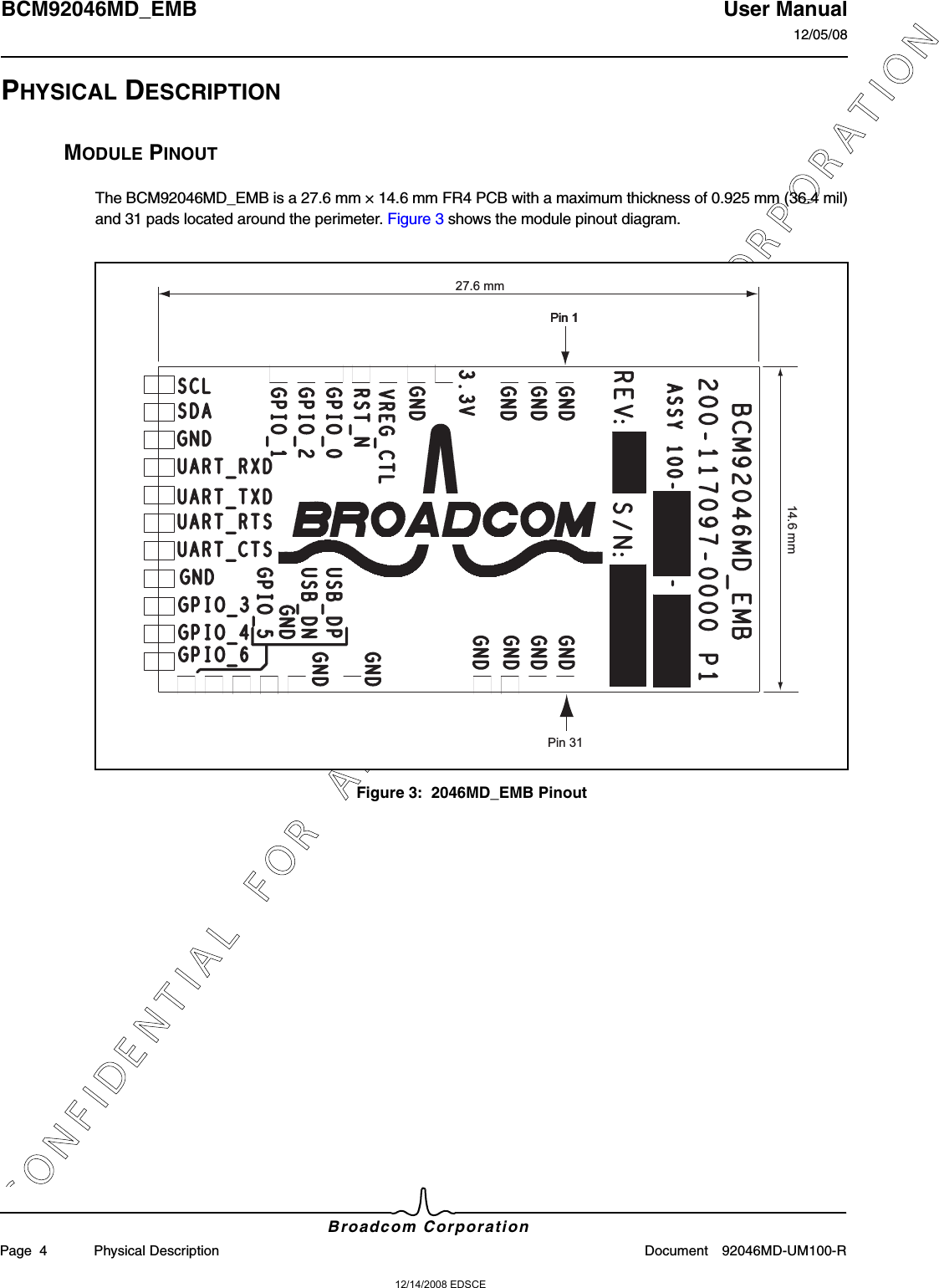
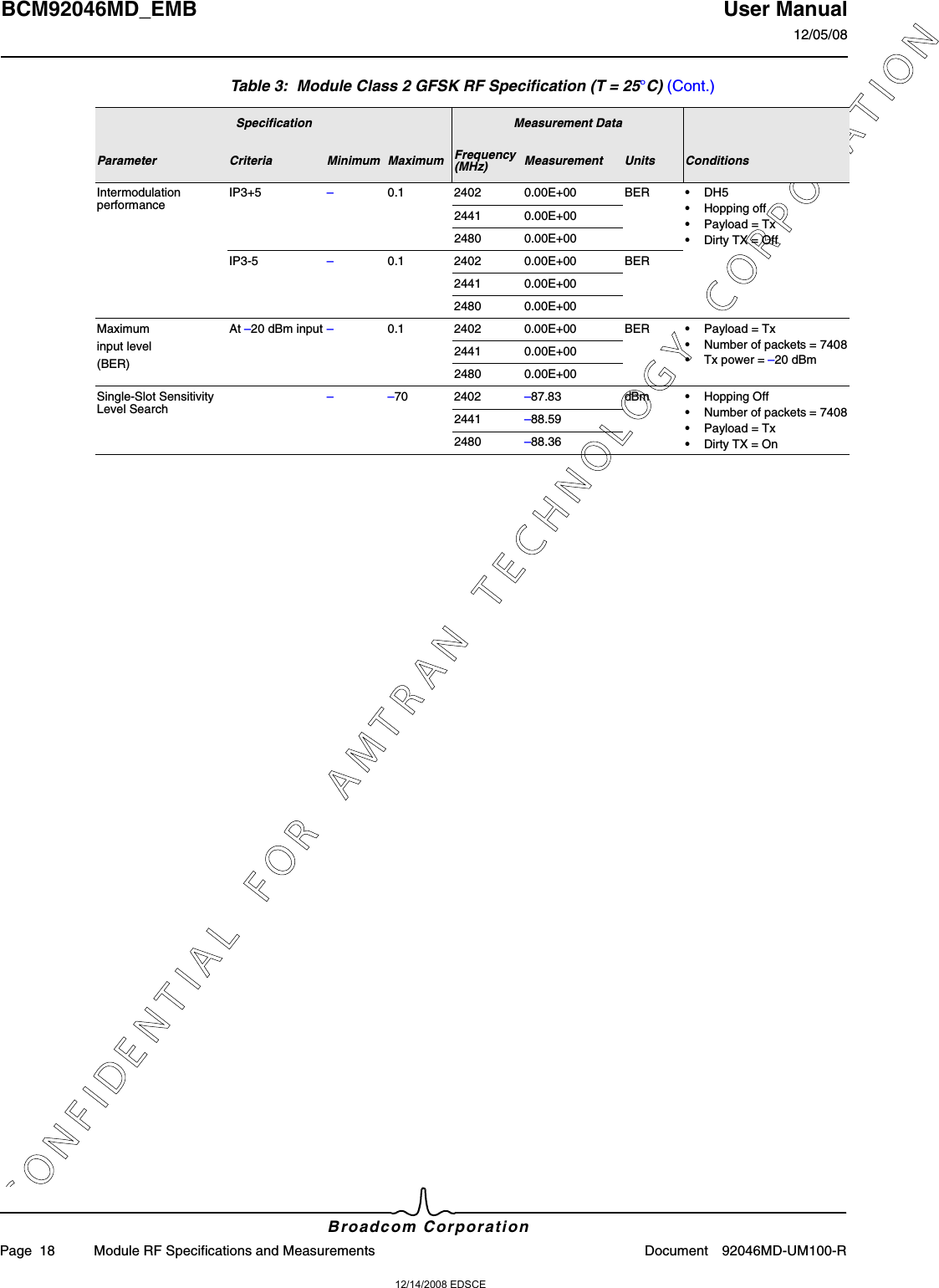
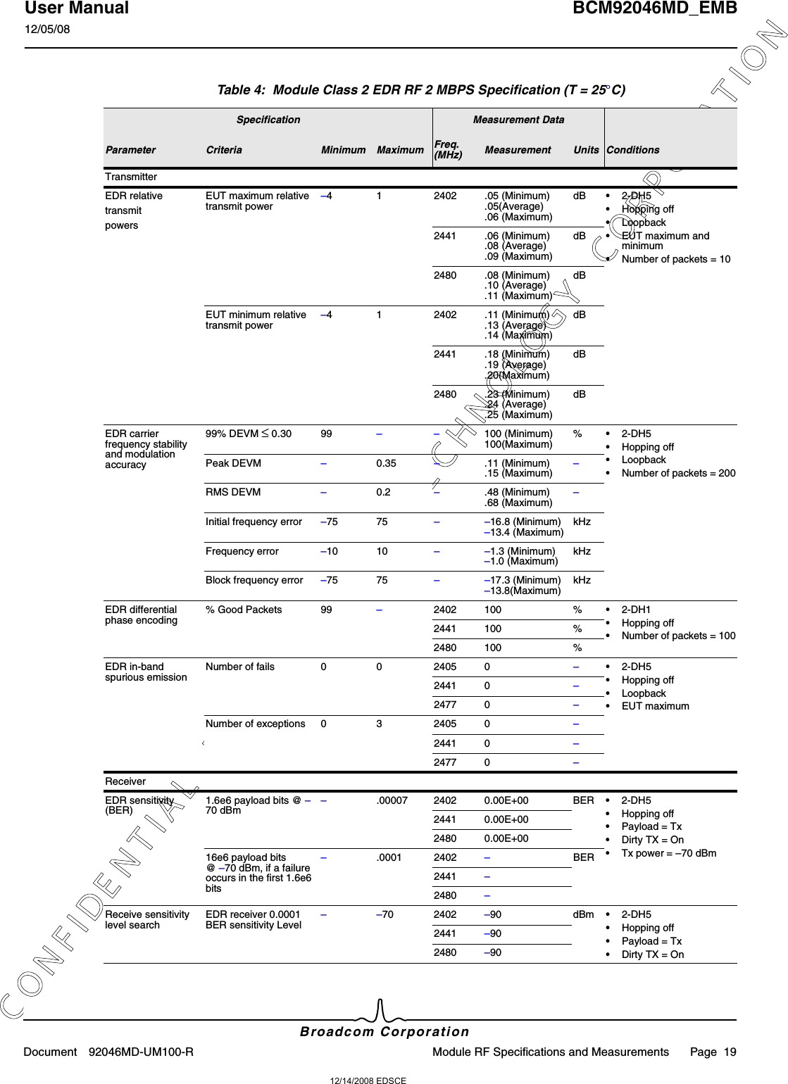
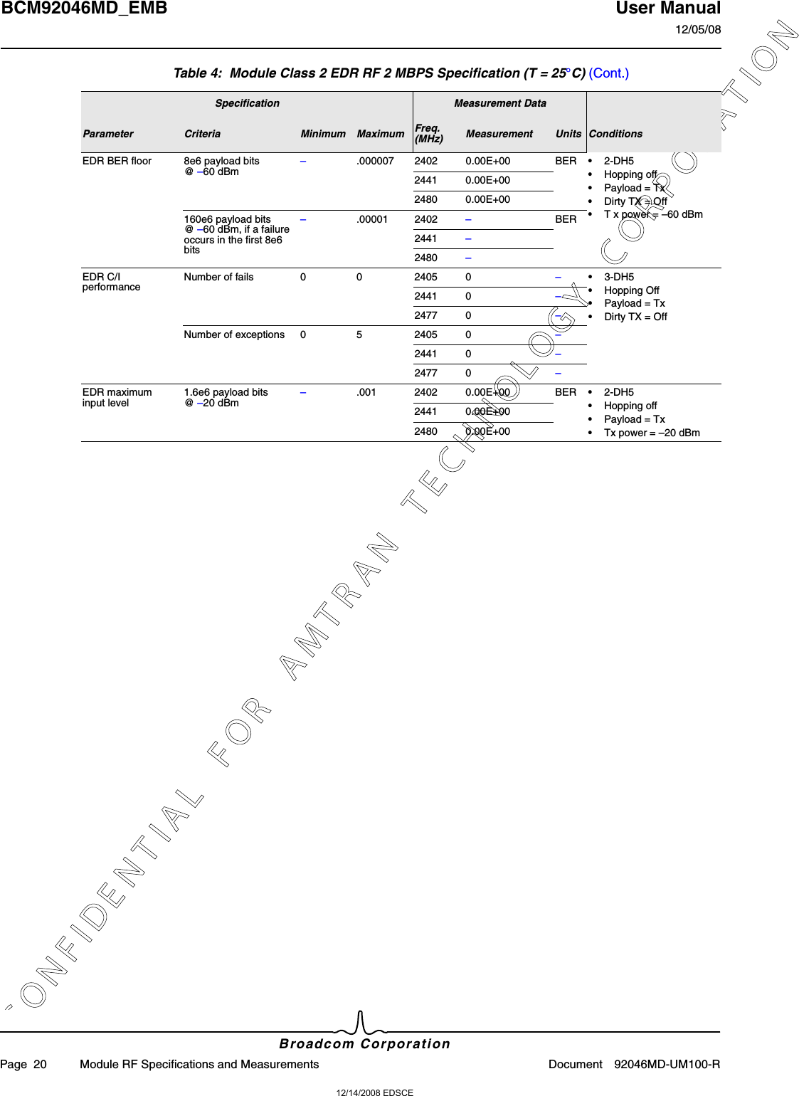
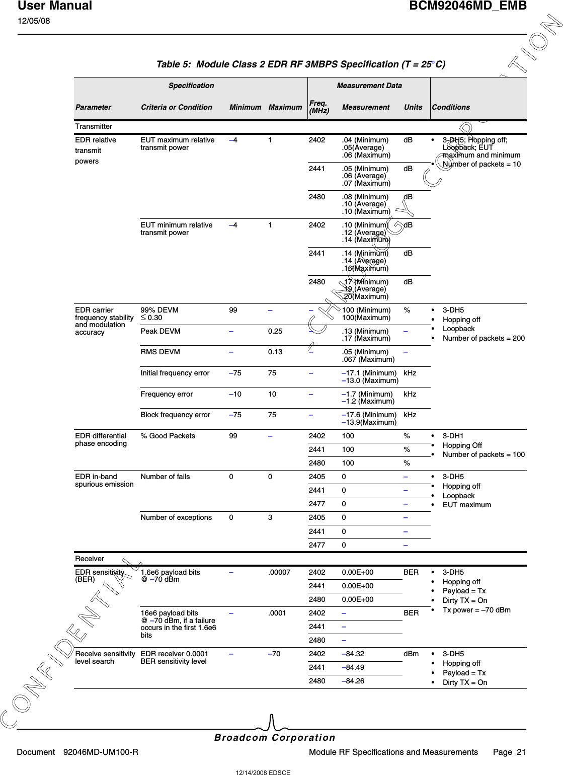
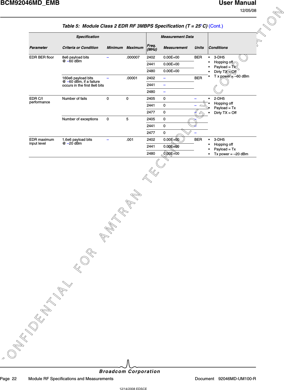
![12/14/2008 EDSCEC O N F I D E N T I A L F O R A M T R A N T E C H N O L O G Y C O R P O R A T I O NBCM92046MD_EMB User Manual12/05/08Broadcom CorporationPage 16 Module RF Specifications and Measurements Document 92046MD-UM100-RMODULE RF SPECIFICATIONS AND MEASUREMENTSTable 3, Table 4 on page 19, and Table 5 on page 21 show the Class 2 RF specifications and measurementsas referenced to the module’s RF input/output port without the PCB antenna (that is, all measurements areconducted not radiated).Table 3: Module Class 2 GFSK RF Specification (T = 25°C)Specification Measurement DataParameter Criteria Minimum Maximum Frequency(MHz) Measurement Units ConditionsTransmitterOutput power ––6 4 2402 1.84 (Pavg min.)1.85 (Pavg max.)2.09 (Peak)dBm •DH5 packet•Hopping on•Loopback•Number of packets = 102441 1.44 (Pavg min.)1.45 (Pavg max.)1.77 (Peak)2480 0.61 (Pavg min.)0.62 (Pavg max.)1.03 (Peak)Power density ––20 –.87 dBm per 100 kHz EIRP•DH5 packet•Hopping off•Loopback•Number of packets = 10Tx output spectrum frequency range –2400 2483.5 2402 2401.23 MHz •Payload = Tx•DH1 packet•PRBS9•Tx power [dBm] = 1.002480 2480.7Tx output spectrum 20 dB bandwidth –0 1 2402 .92 MHz •DH5 packet•Hopping off•Loopback;•Number of packets = 102441 .922480 .92Tx output spectrum, adjacent channelpower|M-N| = 2 ––20 2405 –54.09 dBm •DH5•Hopping Off•Loopback•Number of packets = 102441 –54.322477 –55.09|M-N| ≥ 3––40 2405 –56.96 dBm2441 –49.382477 –49.35Exceptions 0 3 2405 0 –2441 02477 0Fails 0 0 2405 0 –2441 02477 0](https://usermanual.wiki/Amtran-Technology-Co/SV422XVT-BT/User-Guide-1157727-Page-5.png)
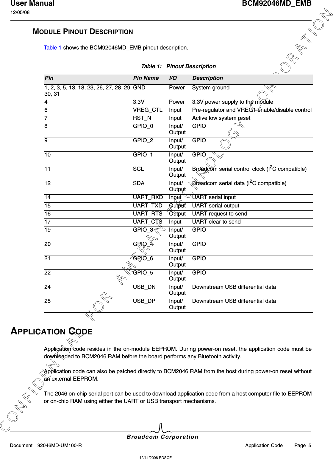
![12/14/2008 EDSCEC O N F I D E N T I A L F O R A M T R A N T E C H N O L O G Y C O R P O R A T I O NUser Manual BCM92046MD_EMB12/05/08Broadcom CorporationDocument 92046MD-UM100-R Module RF Specifications and Measurements Page 17Modulation Delta f2max ≥ 99.9% of all delta f2max115 –2402 132.8 kHz •DH5 Loopback•Number of packets = 10•Change payload = Toggle payload = Continue.2441 1362480 139.1Delta f1(Avg) 140 175 2402 151.9 kHz2441 149.32480 148.1Delta f2 / Delta f1 0.8 –2402 .94 –2441 .982480 1.01Initial carrier frequency tolerance –75 75 2402 –16.8 (Minimum)–15.5 (Average)–13.8 (Maximum)kHz •Hopping on•Number of packets = 10•Loopback2441 –16.1 (Minimum)–15.0 (Average)–13.6 (Maximum)kHz2480 –16.3 (Minimum)–13.1(Average)–11.5 (Maximum)kHzCarrier frequency drift One slot packetdrift [DH1] –25 25 2402 –6kHz•DH1 and DH3 and DH5•Hopping on•Number of packets = 10•Loopback2441 –52480 –6Three slot packet drift [DH3] –40 40 2402 –6kHz2441 –62480 –6Five slot packet drift [DH5] –40 40 2402 –7kHz2441 –62480 –6Drift rate – – 2402 5.33 dB2441 –4.792480 –6.03ReceiverSensitivity (BER) –70 dBm, single-slot packets–0.1 2402 0.00E+00 BER •Hopping off•Number of packets = 740•Payload = T•Dirty TX = On•Tx power = –70 dBm2441 0.00E+002480 0.00E+00–70 dBm, multislot packets –0.1 2402 0.00E+00 BER2441 0.00E+002480 0.00E+00C/IperformanceNumber of fails 0 0 2405 0 –•Payload = Tx•DH1 packet•PRBS9•Tx power [dBm] = 1.002441 02477 0Number of exceptions 0 5 2405 0 –2441 02477 0Table 3: Module Class 2 GFSK RF Specification (T = 25°C) (Cont.)Specification Measurement DataParameter Criteria Minimum Maximum Frequency(MHz) Measurement Units Conditions](https://usermanual.wiki/Amtran-Technology-Co/SV422XVT-BT/User-Guide-1157727-Page-6.png)