Amtran Technology Co SV422XVT-BT Bluetooth Embedded Module User Manual Rev 02
Amtran Technology Co Ltd Bluetooth Embedded Module Rev 02
User Manual Rev 02

12/14/2008 EDSCE
C O N F I D E N T I A L F O R A M T R A N T E C H N O L O G Y C O R P O R A T I O N
92046MD-UM100-R
5300 California Avenue • Irvine, CA 92617 • Phone: 949-926-5000 • Fax: 949-926-5203 12/05/08
User Manual
BCM92046MD_EMB
Bluetooth® Embedded Module

12/14/2008 EDSCE
C O N F I D E N T I A L F O R A M T R A N T E C H N O L O G Y C O R P O R A T I O N
User Manual BCM92046MD_EMB
12/05/08
Broadcom Corporation
Document 92046MD-UM100-R Overview Page 1
Section 1: Overview
INTRODUCTION
The BCM92046MD_EMB is a Bluetooth® embedded module based on the BCM2046 Bluetooth 2.1
specification-compliant stand-alone baseband processor with an integrated 2.4 GHz transceiver. It is fully
compliant with the Bluetooth radio specification and incorporates new modulation schemes to support
enhanced data rates (EDRs) of 2 Mbps and 3 Mbps. The BCM92046MD_EMB module supports both UART
and Universal Serial Bus (USB) version 2.0 full-speed interfaces, and is fully compatible with the HCI interface
specification. The module includes EEPROM, a crystal, and a Printed Circuit Board (PCB) antenna.
FEATURES
The module supports the following features:
•A Bluetooth 2.1 compliant embedded USB module with the following features:
- Secure Simple Pairing (SSP)
- Link Supervision Time Out (LSTO)
- Encryption Pause Resume (EPR)
- Enhance Inquiry Response (EIR)
- Sniff Subrating (SSR)
- Erroneous Data (ED)
- Packet Boundary Flag (PBF)
•A Programmable collaborative coexistence interface
•Class 1 output power capability
•Class 2 RF maximum output power specification of 4 dBm
•Full piconet and scatternet operation
•EDR rates of 2 MBps and 3 MBps
•A high-speed UART interface
•A USB 2.0 full-speed compliant interface
•Built-in Low Power Oscillator (LPO) clock or operation using an external LPO clock
•Full support for power-saving modes.
•Advanced Audio Distribution Profile (A2DP)
•Upgradeable firmware through an EEPROM download
•A PCB antenna
12/14/2008 EDSCE
C O N F I D E N T I A L F O R A M T R A N T E C H N O L O G Y C O R P O R A T I O N
BCM92046MD_EMB User Manual
12/05/08
Broadcom Corporation
Page 4 Physical Description Document 92046MD-UM100-R
PHYSICAL DESCRIPTION
MODULE PINOUT
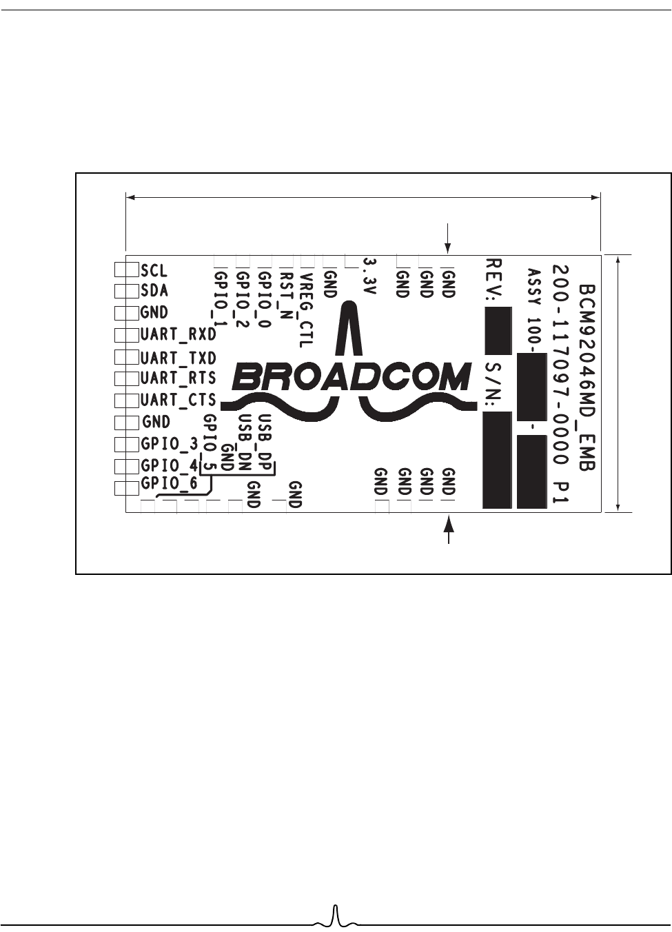
The BCM92046MD_EMB is a 27.6 mm × 14.6 mm FR4 PCB with a maximum thickness of 0.925 mm (36.4 mil)
and 31 pads located around the perimeter. Figure 3 shows the module pinout diagram.
Figure 3: 2046MD_EMB Pinout
Pin 1Pin 1
Pin 31
27.6 mm
14.6 mm

12/14/2008 EDSCE
C O N F I D E N T I A L F O R A M T R A N T E C H N O L O G Y C O R P O R A T I O N
User Manual BCM92046MD_EMB
12/05/08
Broadcom Corporation
Document 92046MD-UM100-R Application Code Page 5
MODULE PINOUT DESCRIPTION
Table 1 shows the BCM92046MD_EMB pinout description.
APPLICATION CODE
Application code resides in the on-module EEPROM. During power-on reset, the application code must be
downloaded to BCM2046 RAM before the board performs any Bluetooth activity.
Application code can also be patched directly to BCM2046 RAM from the host during power-on reset without
an external EEPROM.
The 2046 on-chip serial port can be used to download application code from a host computer file to EEPROM
or on-chip RAM using either the UART or USB transport mechanisms.
Table 1: Pinout Description
Pin Pin Name I/O Description
1, 2, 3, 5, 13, 18, 23, 26, 27, 28, 29,
30, 31
GND Power System ground
4 3.3V Power 3.3V power supply to the module
6 VREG_CTL Input Pre-regulator and VREG1 enable/disable control
7 RST_N Input Active low system reset
8 GPIO_0 Input/
Output
GPIO
9 GPIO_2 Input/
Output
GPIO
10 GPIO_1 Input/
Output
GPIO
11 SCL Input/
Output
Broadcom serial control clock (I2C compatible)
12 SDA Input/
Output
Broadcom serial data (I2C compatible)
14 UART_RXD Input UART serial input
15 UART_TXD Output UART serial output
16 UART_RTS Output UART request to send
17 UART_CTS Input UART clear to send
19 GPIO_3 Input/
Output
GPIO
20 GPIO_4 Input/
Output
GPIO
21 GPIO_6 Input/
Output
GPIO
22 GPIO_5 Input/
Output
GPIO
24 USB_DN Input/
Output
Downstream USB differential data
25 USB_DP Input/
Output
Downstream USB differential data

12/14/2008 EDSCE
C O N F I D E N T I A L F O R A M T R A N T E C H N O L O G Y C O R P O R A T I O N
BCM92046MD_EMB User Manual
12/05/08
Broadcom Corporation
Page 16 Module RF Specifications and Measurements Document 92046MD-UM100-R
MODULE RF SPECIFICATIONS AND MEASUREMENTS
Table 3, Table 4 on page 19, and Table 5 on page 21 show the Class 2 RF specifications and measurements
as referenced to the module’s RF input/output port without the PCB antenna (that is, all measurements are
conducted not radiated).
Table 3: Module Class 2 GFSK RF Specification (T = 25
°
C)
Specification Measurement Data
Parameter Criteria Minimum Maximum Frequency
(MHz) Measurement Units Conditions
Transmitter
Output power ––6 4 2402 1.84 (Pavg min.)
1.85 (Pavg max.)
2.09 (Peak)
dBm •DH5 packet
•Hopping on
•Loopback
•Number of packets = 102441 1.44 (Pavg min.)
1.45 (Pavg max.)
1.77 (Peak)
2480 0.61 (Pavg min.)
0.62 (Pavg max.)
1.03 (Peak)
Power density ––20 –.87 dBm per
100 kHz
EIRP
•DH5 packet
•Hopping off
•Loopback
•Number of packets = 10
Tx output spectrum
frequency range –2400 2483.5 2402 2401.23 MHz •Payload = Tx
•DH1 packet
•PRBS9
•Tx power [dBm] = 1.00
2480 2480.7
Tx output spectrum
20 dB bandwidth –0 1 2402 .92 MHz •DH5 packet
•Hopping off
•Loopback;
•Number of packets = 10
2441 .92
2480 .92
Tx output spectrum,
adjacent channel
power
|M-N| = 2 ––20 2405 –54.09 dBm •DH5
•Hopping Off
•Loopback
•Number of packets = 10
2441 –54.32
2477 –55.09
|M-N| ≥ 3––40 2405 –56.96 dBm
2441 –49.38
2477 –49.35
Exceptions 0 3 2405 0 –
2441 0
2477 0
Fails 0 0 2405 0 –
2441 0
2477 0
12/14/2008 EDSCE
C O N F I D E N T I A L F O R A M T R A N T E C H N O L O G Y C O R P O R A T I O N
User Manual BCM92046MD_EMB
12/05/08
Broadcom Corporation
Document 92046MD-UM100-R Module RF Specifications and Measurements Page 17
Modulation Delta f2max ≥
99.9% of all delta
f2max
115 –2402 132.8 kHz •DH5 Loopback
•Number of packets = 10
•Change payload = Toggle
payload = Continue.
2441 136
2480 139.1
Delta f1(Avg) 140 175 2402 151.9 kHz
2441 149.3
2480 148.1
Delta f2 / Delta f1 0.8 –2402 .94 –
2441 .98
2480 1.01
Initial carrier frequency
tolerance –75 75 2402 –16.8 (Minimum)
–15.5 (Average)
–13.8 (Maximum)
kHz •Hopping on
•Number of packets = 10
•Loopback
2441 –16.1 (Minimum)
–15.0 (Average)
–13.6 (Maximum)
kHz
2480 –16.3 (Minimum)
–13.1(Average)
–11.5 (Maximum)
kHz
Carrier frequency
drift One slot packet
drift [DH1] –25 25 2402 –6kHz•DH1 and DH3 and DH5
•Hopping on
•Number of packets = 10
•Loopback
2441 –5
2480 –6
Three slot packet
drift [DH3] –40 40 2402 –6kHz
2441 –6
2480 –6
Five slot packet
drift [DH5] –40 40 2402 –7kHz
2441 –6
2480 –6
Drift rate – – 2402 5.33 dB
2441 –4.79
2480 –6.03
Receiver
Sensitivity (BER) –70 dBm,
single-slot
packets
–0.1 2402 0.00E+00 BER •Hopping off
•Number of packets = 740
•Payload = T
•Dirty TX = On
•Tx power = –70 dBm
2441 0.00E+00
2480 0.00E+00
–70 dBm,
multislot packets –0.1 2402 0.00E+00 BER
2441 0.00E+00
2480 0.00E+00
C/I
performance
Number of fails 0 0 2405 0 –•Payload = Tx
•DH1 packet
•PRBS9
•Tx power [dBm] = 1.00
2441 0
2477 0
Number of
exceptions 0 5 2405 0 –
2441 0
2477 0
Table 3: Module Class 2 GFSK RF Specification (T = 25
°
C)
(Cont.)
Specification Measurement Data
Parameter Criteria Minimum Maximum Frequency
(MHz) Measurement Units Conditions

12/14/2008 EDSCE
C O N F I D E N T I A L F O R A M T R A N T E C H N O L O G Y C O R P O R A T I O N
BCM92046MD_EMB User Manual
12/05/08
Broadcom Corporation
Page 18 Module RF Specifications and Measurements Document 92046MD-UM100-R
Intermodulation
performance
IP3+5 –0.1 2402 0.00E+00 BER •DH5
•Hopping off
•Payload = Tx
•Dirty TX = Off
2441 0.00E+00
2480 0.00E+00
IP3-5 –0.1 2402 0.00E+00 BER
2441 0.00E+00
2480 0.00E+00
Maximum
input level
(BER)
At –20 dBm input –0.1 2402 0.00E+00 BER •Payload = Tx
•Number of packets = 7408
•Tx power = –20 dBm
2441 0.00E+00
2480 0.00E+00
Single-Slot Sensitivity
Level Search – –70 2402 –87.83 dBm •Hopping Off
•Number of packets = 7408
•Payload = Tx
•Dirty TX = On
2441 –88.59
2480 –88.36
Table 3: Module Class 2 GFSK RF Specification (T = 25
°
C)
(Cont.)
Specification Measurement Data
Parameter Criteria Minimum Maximum Frequency
(MHz) Measurement Units Conditions
12/14/2008 EDSCE
C O N F I D E N T I A L F O R A M T R A N T E C H N O L O G Y C O R P O R A T I O N
User Manual BCM92046MD_EMB
12/05/08
Broadcom Corporation
Document 92046MD-UM100-R Module RF Specifications and Measurements Page 19
Table 4: Module Class 2 EDR RF 2 MBPS Specification (T = 25
°
C)
Specification Measurement Data
Parameter Criteria Minimum Maximum Freq.
(MHz) Measurement Units Conditions
Transmitter
EDR relative
transmit
powers
EUT maximum relative
transmit power –41 2402 .05 (Minimum)
.05(Average)
.06 (Maximum)
dB •2-DH5
•Hopping off
•Loopback
•EUT maximum and
minimum
•Number of packets = 10
2441 .06 (Minimum)
.08 (Average)
.09 (Maximum)
dB
2480 .08 (Minimum)
.10 (Average)
.11 (Maximum)
dB
EUT minimum relative
transmit power
–41 2402 .11 (Minimum)
.13 (Average)
.14 (Maximum)
dB
2441 .18 (Minimum)
.19 (Average)
.20(Maximum)
dB
2480 .23 (Minimum)
.24 (Average)
.25 (Maximum)
dB
EDR carrier
frequency stability
and modulation
accuracy
99% DEVM ≤ 0.30 99 ––100 (Minimum)
100(Maximum)
%•2-DH5
•Hopping off
•Loopback
•Number of packets = 200
Peak DEVM –0.35 –.11 (Minimum)
.15 (Maximum) –
RMS DEVM –0.2 –.48 (Minimum)
.68 (Maximum) –
Initial frequency error –75 75 ––16.8 (Minimum)
–13.4 (Maximum)
kHz
Frequency error –10 10 ––1.3 (Minimum)
–1.0 (Maximum) kHz
Block frequency error –75 75 ––17.3 (Minimum)
–13.8(Maximum) kHz
EDR differential
phase encoding
% Good Packets 99 –2402 100 % •2-DH1
•Hopping off
•Number of packets = 100
2441 100 %
2480 100 %
EDR in-band
spurious emission
Number of fails 0024050 –•2-DH5
•Hopping off
•Loopback
•EUT maximum
2441 0 –
2477 0 –
Number of exceptions 0324050 –
2441 0 –
2477 0 –
Receiver
EDR sensitivity
(BER) 1.6e6 payload bits @ –
70 dBm –.00007 2402 0.00E+00 BER •2-DH5
•Hopping off
•Payload = Tx
•Dirty TX = On
•Tx power = –70 dBm
2441 0.00E+00
2480 0.00E+00
16e6 payload bits
@ –70 dBm, if a failure
occurs in the first 1.6e6
bits
–.0001 2402 –BER
2441 –
2480 –
Receive sensitivity
level search EDR receiver 0.0001
BER sensitivity Level – –70 2402 –90 dBm •2-DH5
•Hopping off
•Payload = Tx
•Dirty TX = On
2441 –90
2480 –90

12/14/2008 EDSCE
C O N F I D E N T I A L F O R A M T R A N T E C H N O L O G Y C O R P O R A T I O N
BCM92046MD_EMB User Manual
12/05/08
Broadcom Corporation
Page 20 Module RF Specifications and Measurements Document 92046MD-UM100-R
EDR BER floor 8e6 payload bits
@ –60 dBm –.000007 2402 0.00E+00 BER •2-DH5
•Hopping off
•Payload = Tx
•Dirty TX = Off
•T x power = –60 dBm
2441 0.00E+00
2480 0.00E+00
160e6 payload bits
@ –60 dBm, if a failure
occurs in the first 8e6
bits
–.00001 2402 –BER
2441 –
2480 –
EDR C/I
performance Number of fails 0024050 –•3-DH5
•Hopping Off
•Payload = Tx
•Dirty TX = Off
2441 0 –
2477 0 –
Number of exceptions 0524050 –
2441 0 –
2477 0 –
EDR maximum
input level 1.6e6 payload bits
@ –20 dBm –.001 2402 0.00E+00 BER •2-DH5
•Hopping off
•Payload = Tx
•Tx power = –20 dBm
2441 0.00E+00
2480 0.00E+00
Table 4: Module Class 2 EDR RF 2 MBPS Specification (T = 25
°
C)
(Cont.)
Specification Measurement Data
Parameter Criteria Minimum Maximum Freq.
(MHz) Measurement Units Conditions
12/14/2008 EDSCE
C O N F I D E N T I A L F O R A M T R A N T E C H N O L O G Y C O R P O R A T I O N
User Manual BCM92046MD_EMB
12/05/08
Broadcom Corporation
Document 92046MD-UM100-R Module RF Specifications and Measurements Page 21
Table 5: Module Class 2 EDR RF 3MBPS Specification (T = 25
°
C)
Specification Measurement Data
Parameter Criteria or Condition Minimum Maximum Freq.
(MHz) Measurement Units Conditions
Transmitter
EDR relative
transmit
powers
EUT maximum relative
transmit power –41 2402 .04 (Minimum)
.05(Average)
.06 (Maximum)
dB •3-DH5; Hopping off;
Loopback; EUT
maximum and minimum
•Number of packets = 10
2441 .05 (Minimum)
.06 (Average)
.07 (Maximum)
dB
2480 .08 (Minimum)
.10 (Average)
.10 (Maximum)
dB
EUT minimum relative
transmit power
–41 2402 .10 (Minimum)
.12 (Average)
.14 (Maximum)
dB
2441 .14 (Minimum)
.14 (Average)
.16(Maximum)
dB
2480 .17 (Minimum)
.19 (Average)
.20(Maximum)
dB
EDR carrier
frequency stability
and modulation
accuracy
99% DEVM
≤ 0.30
99 ––100 (Minimum)
100(Maximum)
%•3-DH5
•Hopping off
•Loopback
•Number of packets = 200
Peak DEVM –0.25 –.13 (Minimum)
.17 (Maximum) –
RMS DEVM –0.13 –.05 (Minimum)
.067 (Maximum) –
Initial frequency error –75 75 ––17.1 (Minimum)
–13.0 (Maximum)
kHz
Frequency error –10 10 ––1.7 (Minimum)
–1.2 (Maximum) kHz
Block frequency error –75 75 ––17.6 (Minimum)
–13.9(Maximum) kHz
EDR differential
phase encoding
% Good Packets 99 –2402 100 % •3-DH1
•Hopping Off
•Number of packets = 100
2441 100 %
2480 100 %
EDR in-band
spurious emission
Number of fails 00 2405 0 –•3-DH5
•Hopping off
•Loopback
•EUT maximum
2441 0 –
2477 0 –
Number of exceptions 03 2405 0 –
2441 0 –
2477 0 –
Receiver
EDR sensitivity
(BER) 1.6e6 payload bits
@ –70 dBm –.00007 2402 0.00E+00 BER •3-DH5
•Hopping off
•Payload = Tx
•Dirty TX = On
•Tx power = –70 dBm
2441 0.00E+00
2480 0.00E+00
16e6 payload bits
@ –70 dBm, if a failure
occurs in the first 1.6e6
bits
–.0001 2402 –BER
2441 –
2480 –
Receive sensitivity
level search EDR receiver 0.0001
BER sensitivity level – –70 2402 –84.32 dBm •3-DH5
•Hopping off
•Payload = Tx
•Dirty TX = On
2441 –84.49
2480 –84.26

12/14/2008 EDSCE
C O N F I D E N T I A L F O R A M T R A N T E C H N O L O G Y C O R P O R A T I O N
BCM92046MD_EMB User Manual
12/05/08
Broadcom Corporation
Page 22 Module RF Specifications and Measurements Document 92046MD-UM100-R
EDR BER floor 8e6 payload bits
@ –60 dBm –.000007 2402 0.00E+00 BER •3-DH5
•Hopping off
•Payload = Tx
•Dirty TX = Off
•T x power = –60 dBm
2441 0.00E+00
2480 0.00E+00
160e6 payload bits
@ –60 dBm, if a failure
occurs in the first 8e6 bits
–.00001 2402 –BER
2441 –
2480 –
EDR C/I
performance Number of fails 00 2405 0 –•2-DH5
•Hopping off
•Payload = Tx
•Dirty TX = Off
2441 0 –
2477 0 –
Number of exceptions 05 2405 0 –
2441 0 –
2477 0 –
EDR maximum
input level 1.6e6 payload bits
@ –20 dBm –.001 2402 0.00E+00 BER •3-DH5
•Hopping off
•Payload = Tx
•Tx power = –20 dBm
2441 0.00E+00
2480 0.00E+00
Table 5: Module Class 2 EDR RF 3MBPS Specification (T = 25
°
C)
(Cont.)
Specification Measurement Data
Parameter Criteria or Condition Minimum Maximum Freq.
(MHz) Measurement Units Conditions

12/14/2008 EDSCE
C O N F I D E N T I A L F O R A M T R A N T E C H N O L O G Y C O R P O R A T I O N
User Manual BCM92046MD_EMB
12/05/08
Broadcom Corporation
Document 92046MD-UM100-R Ordering Information Page 23
Section 3: Ordering Information
Contact your Broadcom representative for a BCM92046MD_EMB kit. See Table 6 for ordering information.
Table 6: Ordering Information
Description Part Number
BCM92046 Bluetooth Embedded Module BCM92046MD_EMB

Declaration of Conformity Label & Marking Requirements
This equipment has been tested and found to comply with the limits for a Class B digital device,
pursuant to Part 15 of the FCC Rules. These limits are designed to provide reasonable protection
against harmful interference in a residential installation. This equipment generates, uses and can
radiate radio frequency energy and, if not installed and used in accordance with the instructions, may
cause harmful interference to radio communications. However, there is no guarantee that interference
will not occur in a particular installation. If this equipment does cause harmful interference to radio
or television reception, which can be determined by turning the equipment off and on, the user is
encouraged to try to correct the interference by one or more of the following measures:
-- Reorient or relocate the receiving antenna.
-- Increase the separation between the equipment and receiver.
-- Connect the equipment into an outlet on a circuit different from that to which the
receiver is connected.
-- Consult the dealer or an experienced radio/TV technician for help.
FCC Caution: The user is cautioned that any changes or modifications not expressly approved by
Renishaw plc, or authorised representative could void the user’s authority to operate the equipment.
This device complies with part 15 of the FCC Rules. Operation is subject to the following two conditions:
(1) This device may not cause harmful interference, and
(2) this device must accept any interference received, including interference that may cause undesired
operation.