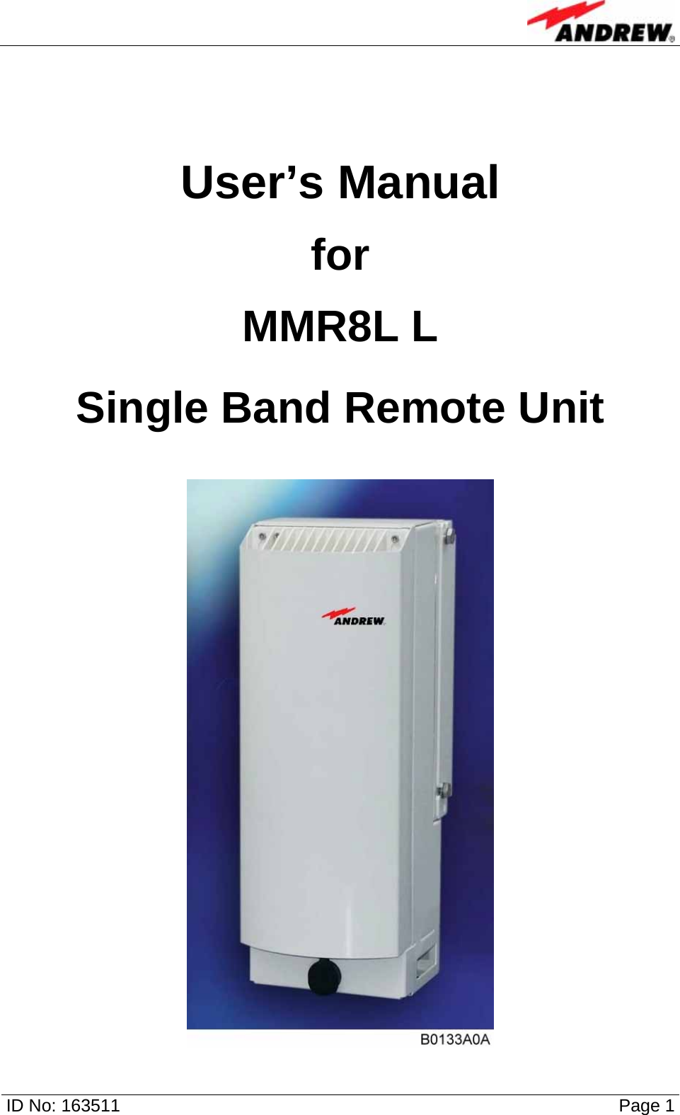
Andrew Wireless Innovations Group RPT-MMR8L Booster User Manual User s Manual
Andrew Wireless Innovations Group Booster User s Manual
UserManual.wiki
>
Andrew Wireless Innovations Group
>
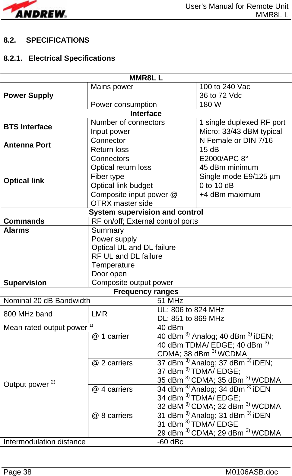
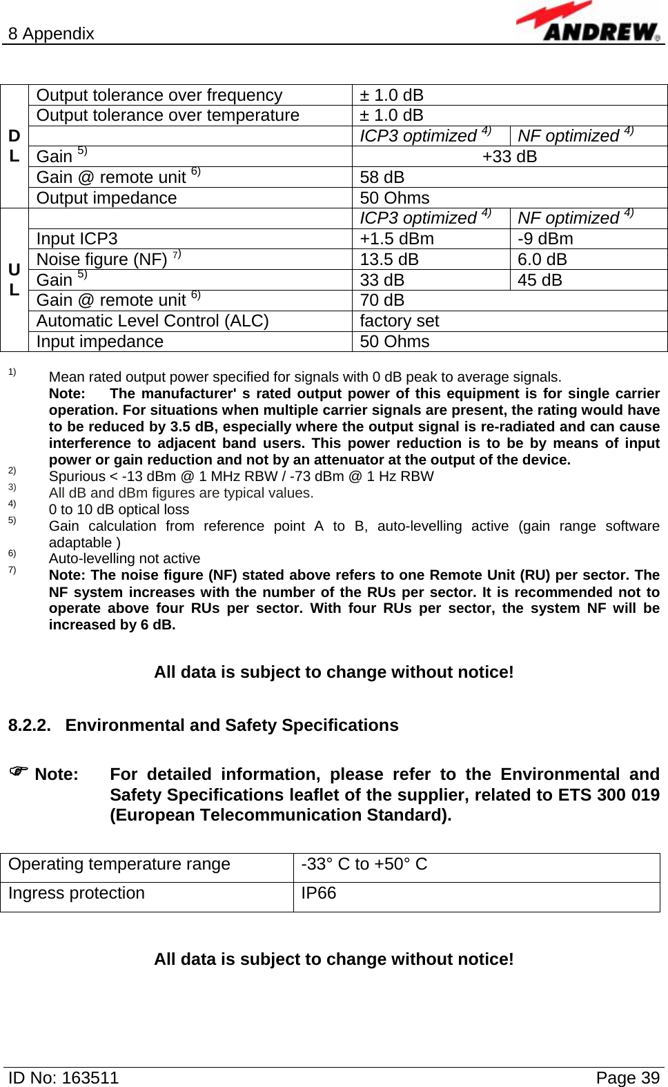
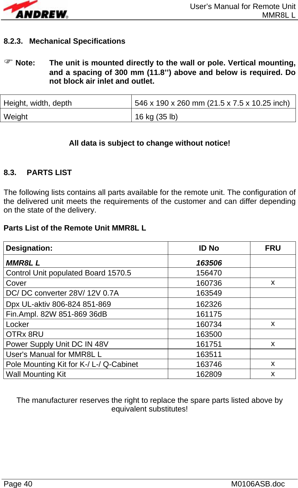
RPT MMR8L User Manual
Manual
Navigation menu
Upload a User Manual
Namespaces
Wiki Guide
HTML
PDF
Info
Views
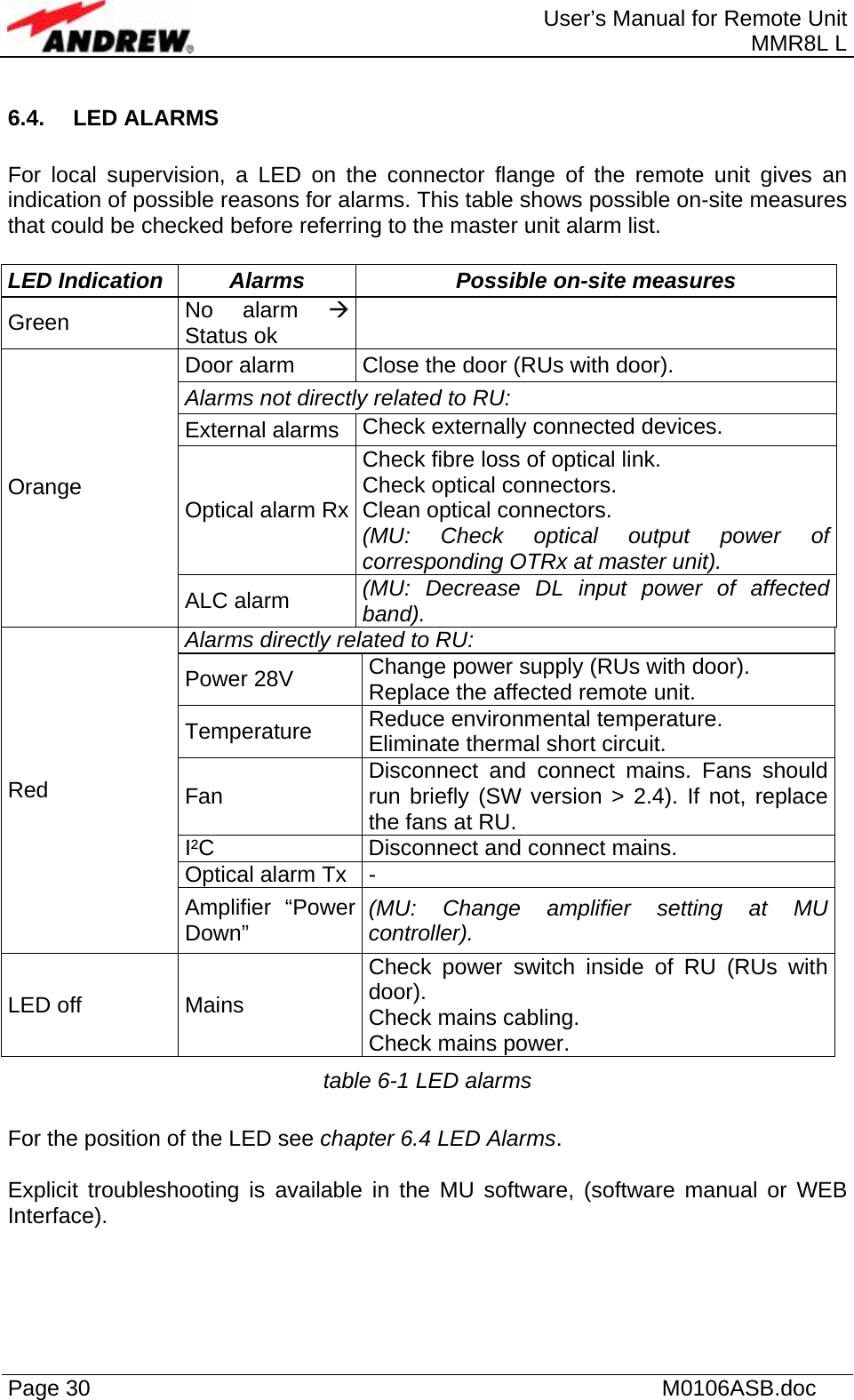
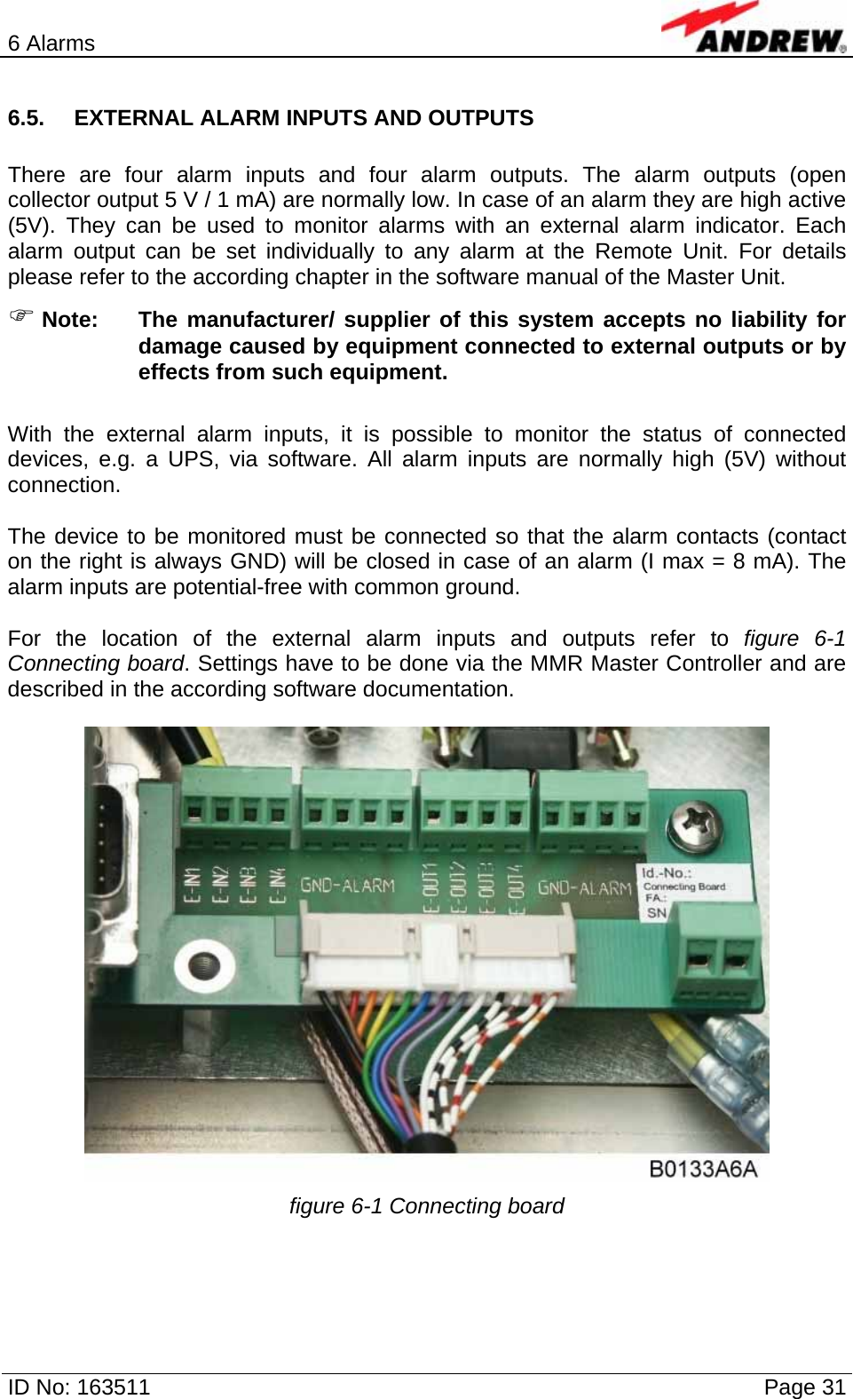
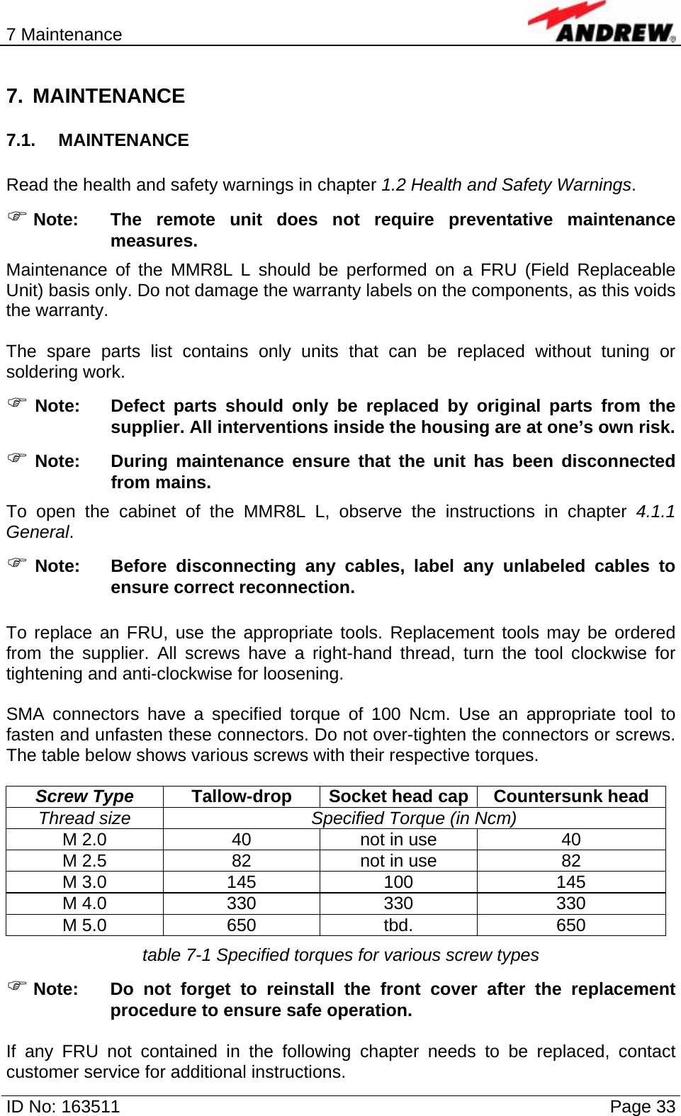
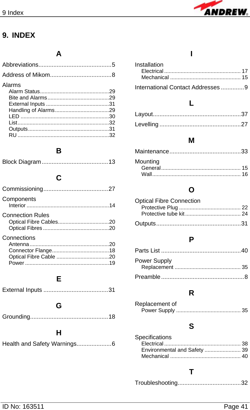
User Manual
Discussion / Help
Navigation