Andrew Wireless Innovations Group RPT-MMR8L Booster User Manual User s Manual
Andrew Wireless Innovations Group Booster User s Manual
Manual
ID No: 163511 Page 1
User’s Manual
for
MMR8L L
Single Band Remote Unit

User’s Manual for Remote Unit
MMR8L L
Page 2 M0106ASB.doc
© Copyright 2005 Mikom GmbH
All rights reserved.
All information contained in this manual has been revised thoroughly. Yet Mikom
accepts no liability for any omissions or faults.
Mikom reserves the right to change all hard- and software characteristics without
notice.
Names of products mentioned herein are used for identification purposes only and
may be trademarks and/or registered trademarks of their respective companies.
No parts of this publication may be reproduced, stored in a retrieval system,
transmitted in any form or by any means, electronical, mechanical photocopying,
recording or otherwise, without prior written permission of the publisher.
Mikom GmbH An Andrew Company, 27-January-2005

ID No: 163511 Page 3
TABLE OF CONTENTS
1. GENERAL 5
1.1. USED ABBREVIATIONS 5
1.2. HEALTH AND SAFETY WARNINGS 6
1.3. PREAMBLE 8
1.4. INTERNATIONAL CONTACT ADDRESSES 9
2. INTRODUCTION 11
2.1. PURPOSE 11
2.2. THE MMR8L L SINGLE BAND REMOTE UNIT 11
3. FUNCTIONAL DESCRIPTION 13
3.1. GENERAL 13
3.2. COMPONENTS OF THE MMR8L L REMOTE UNIT 14
4. INSTALLATION 15
4.1. MECHANICAL INSTALLATION 15
4.1.1. General 15
4.1.2. Wall and Pole Mounting 16
4.2. ELECTRICAL INSTALLATION 17
4.2.1. General 17
4.2.2. Connections 18
4.2.3. Grounding 18
4.2.4. Power Connection 19
4.2.5. Connection of the Antenna Cables 20
4.2.6. Optical Fibre Cable Connection 20
4.2.7. Protective Tube Kit 24
5. COMMISSIONING 27
5.1. GENERAL 27
5.2. AUTO-LEVELLING 27
6. ALARMS 29
6.1. BITE AND ALARMS 29
6.2. HANDLING OF ALARMS 29
6.3. ALARM STATUS 29
6.4. LED ALARMS 30
6.5. EXTERNAL ALARM INPUTS AND OUTPUTS 31
6.6. TROUBLESHOOTING 32

User’s Manual for Remote Unit
MMR8L L
Page 4 M0106ASB.doc
7. MAINTENANCE 33
7.1. MAINTENANCE 33
7.2. GENERAL 34
7.3. REPLACEMENT OF POWER SUPPLY 35
8. APPENDIX 37
8.1. LAYOUT 37
8.2. SPECIFICATIONS 38
8.2.1. Electrical Specifications 38
8.2.2. Environmental and Safety Specifications 39
8.2.3. Mechanical Specifications 40
8.3. PARTS LIST 40
9. INDEX 41
10. LIST OF CHANGES 42
FIGURES AND TABLES
figure 3-1 Configuration of an MMR8L L remote unit................................................ 13
figure 3-2 MMR8L L, base ........................................................................................ 14
figure 3-3 MMR8L L, lid ............................................................................................ 14
figure 4-1 Wall mounting........................................................................................... 16
figure 4-2 Pole mounting .......................................................................................... 16
figure 4-3 Connector flange ...................................................................................... 18
figure 4-4 Grounding bolt.......................................................................................... 18
figure 4-5 AC mains plug .......................................................................................... 19
figure 4-6 DC mains plug.......................................................................................... 19
figure 4-7 Protective plug assembly.......................................................................... 22
figure 4-8 Tube kit installation................................................................................... 25
figure 6-1 Connecting board ..................................................................................... 31
figure 7-1 Locker with key......................................................................................... 34
figure 7-2 Front and top cover screws ...................................................................... 34
figure 7-3 Position of mains power switch................................................................. 34
figure 7-4 Power supply screws................................................................................ 35
figure 8-1 Layout of the remote unit.......................................................................... 37
table 1-1 List of international contact addresses......................................................... 9
table 6-1 LED alarms................................................................................................ 30
table 7-1 Specified torques for various screw types ................................................. 33

1 General
ID No: 163511 Page 5
1. GENERAL
1.1. USED ABBREVIATIONS
ALC Automatic Level Control
AMPS American Mobile Phone System or Advanced Mobile Phone System
APAC Automatic Power Adjustment Circuit
BCCH Broadcast Control Channel
BITE Built In Test Equipment
BTS Base Transceiver Station
CDMA Code Division Multiple Access
CEPT Conférénce Européenne des Postes et Télécommunications
CF Center Frequency
CFO Center Frequency Offset
DL Downlink
EDGE Enhanced Data Rates for GSM Evolution
ESD Electrostatic Discharge
ETS European Telecommunication Standard
ETSI European Telecommunication Standards Institute
FSK Frequency Shift Keying
GSM Global System for Mobile Communication
I2C-Bus Inter Integrated Circuit Bus (Philips)
ID No Identification Number
IF Intermediate Frequency
LMT Local Maintenance Terminal
MS Mobile Station
NSO Network Supervision Option
OMC Operation and Maintenance Center
PCMCIA Personal Computer Modem Communication International Association
PCS Personal Communication System
PSTN Public Switched Telephone Network
Rev Revision
RF Radio Frequency
RLP Radio Link Protocol
RSSI Receive Signal Strength Indication
RTC Real Time Clock
RX Receiver
SCL Serial Clock
SDA Serial Data
TCH Traffic Channel
TDMA Time Division Multiple Access
TX Transmitter
UL Uplink
UMTS Universal Mobile Telecommunication System
UPS Uninterruptible Power Supply
VSWR Voltage Standing Wave Ratio

User’s Manual for Remote Unit
MMR8L L
Page 6 M0106ASB.doc
1.2. HEALTH AND SAFETY WARNINGS
1. Only suitably qualified personnel is allowed to work on this unit and only after
becoming familiar with all safety notices, installation, operation and maintenance
procedures contained in this manual.
2. Read and obey all the warning labels attached to the unit. Make sure that the
warning labels are kept in a legible condition and replace any missing or
damaged labels.
3. Obey all general and regional installation and safety regulations relating to work
on high voltage installations, as well as regulations covering correct use of tools
and personal protective equipment.
4. Keep operating instructions within easy reach and make them available to all
users.
5. It is the responsibility of the network provider to implement prevention measures
to avoid health hazards which may be associated to radiation from the antenna(s)
connected to the unit.
6. For US and Canadian installations: To comply with FCC RF exposure compliance
requirements, the following antenna installation and device operating
configurations must be satisfied: A separation distance of at least 40 cm must be
maintained between the antenna of this device and all persons. RF exposure
compliance may need to be addressed at the time of licensing, as required by the
responsible FCC Bureau(s), including antenna co-location requirements of
1.1307(b)(3). Maximum permissible antenna gain, including coaxial cable loss, is
0 dBi.
7. Make sure access is restricted to qualified personnel.
8. Use this equipment only for the purpose specified by the manufacturer. Do not
carry out any modifications or fit any spare parts which are not sold or
recommended by the manufacturer. This could cause fires, electric shock or other
injuries.
9. Due to power dissipation, the remote unit may reach a very high temperature.
10. Before opening the unit or (dis-)connecting the mains connector at the remote
unit, ensure that mains supply is disconnected.
11. ESD precautions must be observed! Before commencing maintenance work, use
the available grounding system to connect ESD protection measures.
12. This unit complies with European standard EN60950.

1 General
ID No: 163511 Page 7
13. Make sure the system settings are according to the intended use (see also
product information of manufacturer) and regulatory requirements are met.
14. Although the remote unit is internally protected against overvoltage, it is strongly
recommended to earth the antenna cables close to the remote unit’s antenna
connectors for protection against atmospheric discharge.
15. Laser radiation – Class 1! Do not stare into the beam; do not view it directly or
with optical instruments.

User’s Manual for Remote Unit
MMR8L L
Page 8 M0106ASB.doc
1.3. PREAMBLE
Mikom An Andrew Company is a leading manufacturer of coverage equipment for
mobile radio networks, specializing in low cost, high performance, RF and optical
repeaters. Our optical distributed networks and RF repeater systems provide
coverage for every application: outdoor use, indoor installations, tunnels, subways
and many more.
Mikom has engineering and manufacturing facilities in Germany, Italy and the USA.
In addition, it maintains many field engineering offices throughout the world.
Mikom GmbH operates a quality management system which complies with the
requirements of ISO 9001. All equipment is manufactured using only highly reliable
materials. In order to ensure constant first-rate quality of the products, a
comprehensive quality assurance has been conducted at all fabrication stages. Every
component leaves the factory only after a thorough final acceptance test,
accompanied by a test certificate guaranteeing optimal function.
The declaration of conformity for the product is available on request via the local
offices or from Mikom GmbH An Andrew Company directly.
Any intervention must be carried out by authorized persons only. If technical
assistance for the product is required, please contact the local office or Mikom
directly at one of the following addresses:
Mikom GmbH An Andrew Company
Industriering 10
86675 Buchdorf
Germany
Phone: +49 (0) 9099 69 0
Fax: +49 (0) 9099 69 930
email: WIsupport.germany@andrew.com
for The Americas:
Mikom US An Andrew Company
Phone: +1 (919) 771-2570
email: WIsupport.us@andrew.com
When set-up is performed according to this manual, the system will operate without
complications for a significant length of time.

1 General
ID No: 163511 Page 9
1.4. INTERNATIONAL CONTACT ADDRESSES
in Australia
6 Stuart Street
Padstow NSW 2211
Australia
Phone: +61 (2) 9774-4200
Fax: +61 (2) 9774-4500
email:
WIsupport.australia@andrew.com
in France
Z.I. des Ebisoires
78370 Plaisir
France
Phone: +33 (1)30-79-15-36
Fax: +33 (1) 30-55-55-37
email:
WIsupport.france@andrew.com
in the USA
108 Rand Park Drive
Garner
NC 27529
USA
Phone: +1 (919) 771-2570
Fax: + 1 (919) 771-
email:
WIsupport.us@andrew.com
in the UK
Guildgate House
Pelican Lane
Newbury
RG14 1NX, Berkshire, U.K.
Phone: +44 (1635) 569-695
Fax: +44 (1635) 569-463
email:
WIsupport.uk@andrew.com
in China
Rm 915 Chevalier
Commercial Centre; 8 Wang
Hoi Rd; Kowloon Bay SAR,
Hong Kong
Phone: +852 3106-6100
Fax: +852 2751-7800
email:
WIsupport.china@andrew.com
in Canada
1815 Ironstone Manor, # 12
Pickering, Ontario L1W 3W9
Canada
Phone: +1 (905) 839-3474
Fax: +1 (905) 839-4663
email:
WIsupport.canada@andrew.com
in Switzerland
Tiergartenweg 1
4710 Balsthal
Switzerland
Phone: +41 (6238) 61260
Fax: +41 (6238) 61261
email:
WIsupport.switzerland@andrew.com
in Italy
Via De Crescenzi 40
48018 Faenza
Italy
Phone: +39 0546 697111
Fax: +39 0546 682768
email:
WIsupport.italia@andrew.com
in Austria
Weglgasse 10
2320 Schwechat
Austria
Phone: +43 (1) 706 – 3999
Fax: +43 (1) 706 – 39999
email:
WIsupport.austria@andrew.com
in the Czech Republic
U Morusi 888
530 06 Pardubice-Svitkov
Czech. Republic
Phone: +42 (0406) 301280
Fax: +42 (0406) 301298
email:
WIsupport.czechrep@andrew.com
table 1-1 List of international contact addresses

User’s Manual for Remote Unit
MMR8L L
Page 10 M0106ASB.doc
For your notes:

2 Introduction
ID No: 163511 Page 11
2. INTRODUCTION
2.1. PURPOSE
Cellular telephone systems transmit signals in two directions between base
transceiver station (BTS) and mobile stations (MS) within the signal coverage area.
If weak signal transmissions occur within the coverage area because of indoor
applications, topological conditions or distance from the transmitter, extension of the
transmission range can be achieved by means of an optical distribution system.
Such a system contains an optical master unit and a remote unit. The number of the
remote unit depends on the hardware and software configuration. The remote unit is
connected to the master unit with optical links. The optical loss must be less than 10
dB inclusive optical couplers or splitters.
The master unit is the connection to the base transceiver stations. The configuration
of a master unit depends on the number of the remote units and the frequency range.
The optical transmission uses WDM-systems with a wavelength of 1550 nm in the
uplink and 1310 nm in the downlink.
2.2. THE MMR8L L SINGLE BAND REMOTE UNIT
The MMR8L L is a single-band multi-operator remote unit. It is used in conjunction
with a master unit in the MMR optical distribution system. This system transports the
whole LMR band simultaneously providing a cost effective solution for distributing
capacity from one or more base stations.
The MMR8L L transports signals on the RF layer in a very inexpensive manner. This
means that services from various operators can be transmitted simultaneously from a
cluster of base station to a remote location over the same fibre.

User’s Manual for Remote Unit
MMR8L L
Page 12 M0106ASB.doc
For your notes:
3 Functional Description
ID No: 163511 Page 13
3. FUNCTIONAL DESCRIPTION
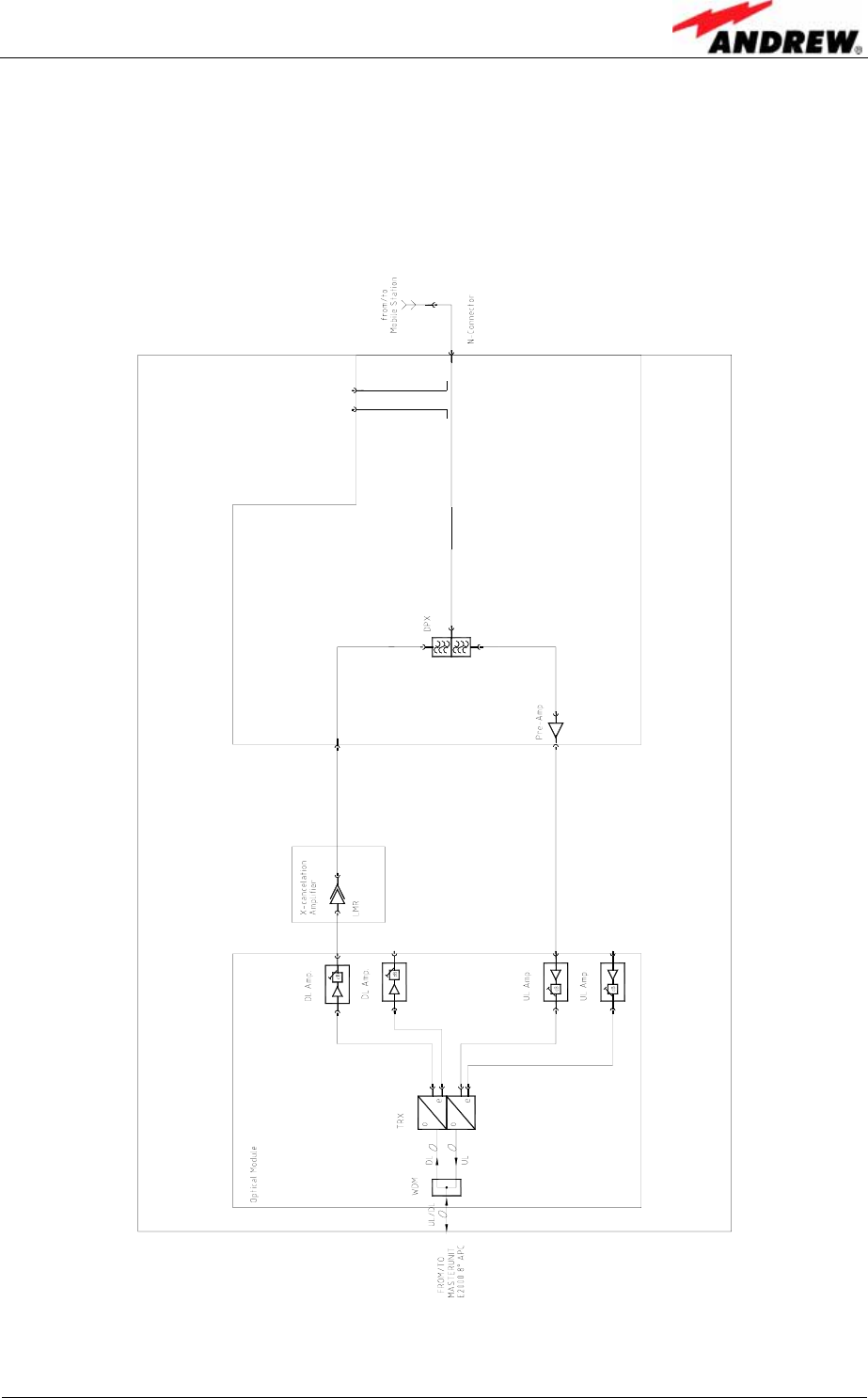
3.1. GENERAL
The following figure shows the configuration of an MMR8L L remote unit.
E1099BR
figure 3-1 Configuration of an MMR8L L remote unit
User’s Manual for Remote Unit
MMR8L L
Page 14 M0106ASB.doc
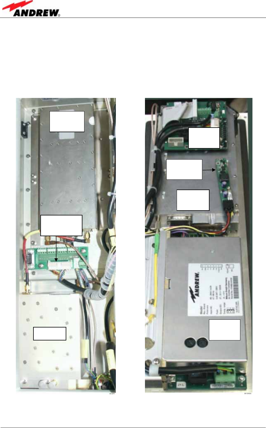
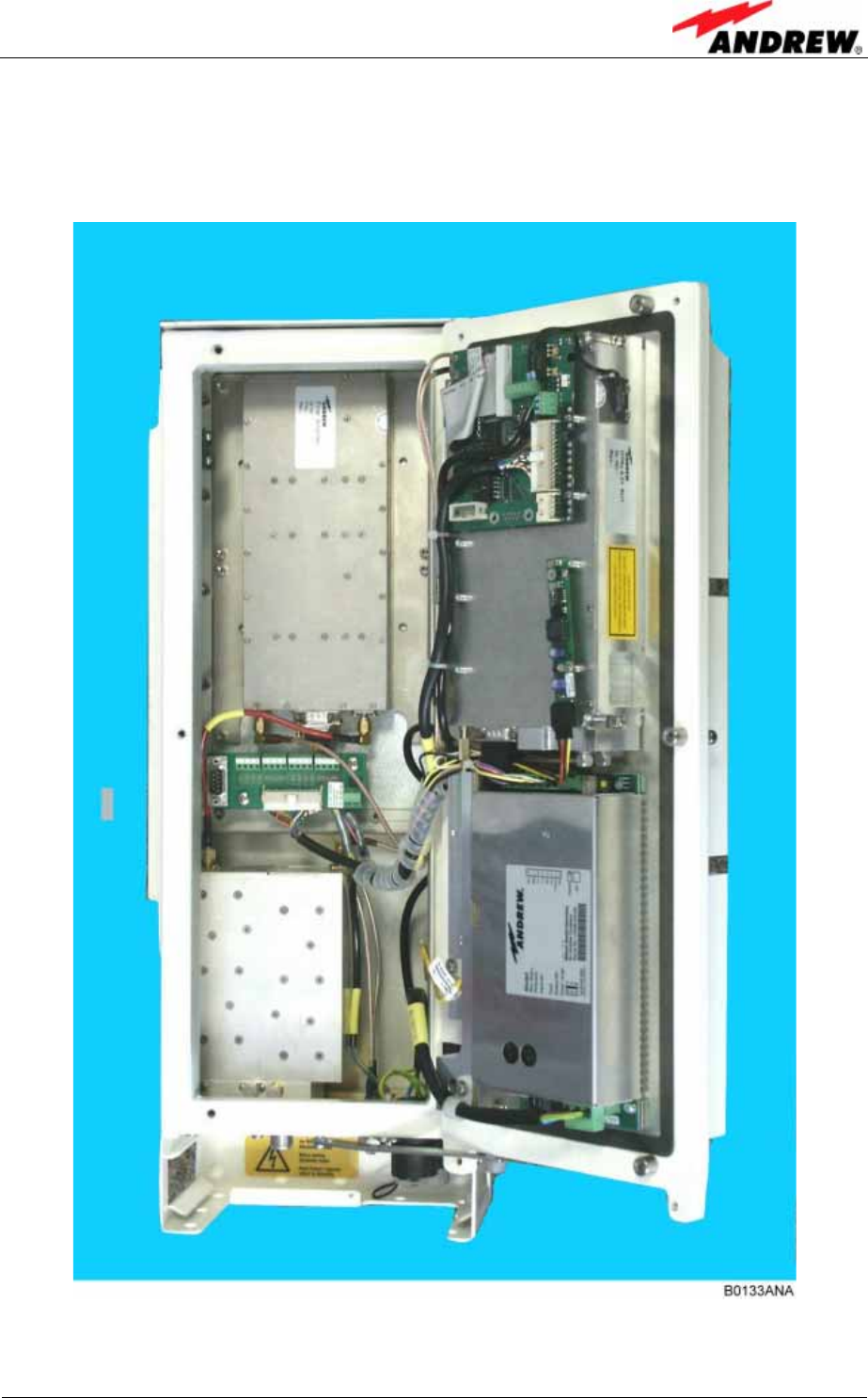
3.2. COMPONENTS OF THE MMR8L L REMOTE UNIT
The actual configuration of the remote unit can be seen at the configuration list which
is part of the delivery.
The following figure shows an exemplary view of an MMR8L L remote unit to
illustrate the individual components.
figure 3-2 MMR8L L, base figure 3-3 MMR8L L, lid
Duplexer
Final
Amplifier
Connecting
Board
Power
Supply
Optical
interface
Control
Board
DC/ DC
converter
4 Installation
ID No: 163511 Page 15
4. INSTALLATION
4.1. MECHANICAL INSTALLATION
4.1.1. General
Read the health and safety warnings in chapter 1.2 Health and Safety Warnings.
1. Do not install the unit in a way or at a place where the specifications
outlined in the Environmental and Safety Specifications leaflet of the
manufacturer are not met.
2. It is strongly recommended to install the unit vertically. If a different
installation of the remote unit is required, please contact customer service
for further information.
3. It is recommended only to use the mounting hardware delivered by the
manufacturer. If different mounting hardware is used, the specifications for
stationary use of the remote unit must not be exceeded.
) Note: Exceeding the specified load limits may cause the loss of warranty!
4. The unit is considerably heavy. Make sure that a suitable mounting
surface is used. Ensure there is adequate manpower to handle the weight of
the system.
5. Due to power dissipation, the remote unit may reach a very high
temperature. Ensure sufficient airflow for ventilation. Above and below the
unit a minimum distance of 300 mm to ceiling, floor, etc. has to be kept.
Also observe the instructions in the individual mounting procedures.
If any different or additional mounting material is used, ensure that the mounting
remains as safe as the mounting designed by the manufacturer. Ensure that the
static and dynamic strengths are adequate for the environmental conditions of the
site. The mounting itself must not vibrate, swing or move in any way that might cause
damage to the remote unit.
) Note: The remote unit is delivered with a pre-mounted front cover. This
cover is of vital importance for the passive cooling of the unit. Thus,
do not operate the unit without cover.
User’s Manual for Remote Unit
MMR8L L
Page 16 M0106ASB.doc
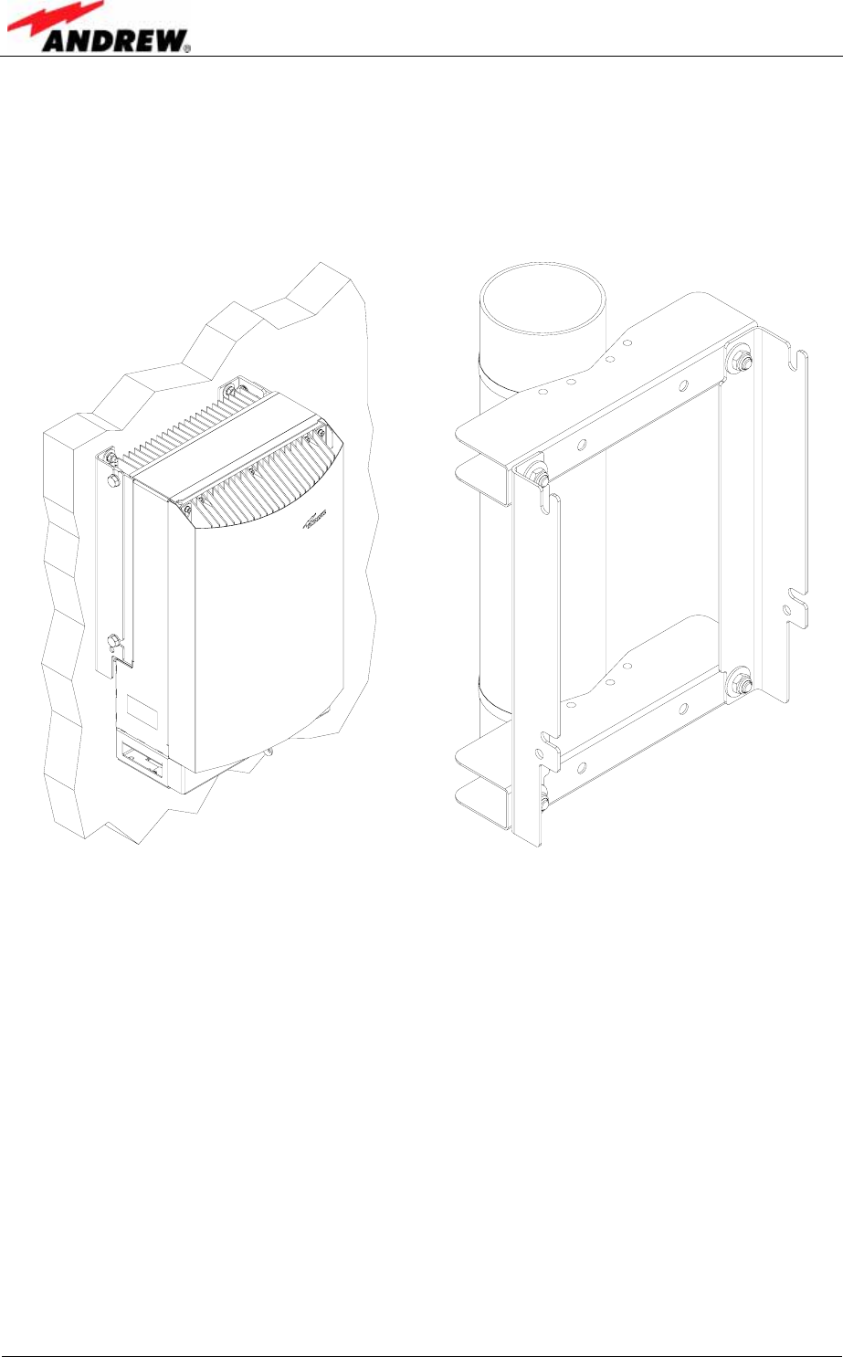
4.1.2. Wall and Pole Mounting
Wall and pole mounting equipment for the unit is available. For the according
mounting please refer to the mounting plan (drawing) that is part of the delivery.
figure 4-1 Wall mounting figure 4-2 Pole mounting
V1628M0 V1628M1

4 Installation
ID No: 163511 Page 17
4.2. ELECTRICAL INSTALLATION
4.2.1. General
Read the health and safety warnings in chapter 1.2 Health and Safety Warnings.
1. This unit contains dangerous voltages. Loss of life, severe personal injury or
property damage can be the result if the instructions contained in this manual are
not followed.
2. It is compulsory to ground the unit before connecting power supply. A grounding
bolt is provided on the cabinet to connect the ground bonding cable.
3. Although the remote unit is internally protected against overvoltage, it is strongly
recommended to earth the antenna cables close to the remote unit’s antenna
connectors for protection against atmospheric discharge. In areas with strong
lightning it is strongly recommended to insert additional lightning protection.
4. If the mains connector of the remote unit is not easily accessible, a separation
device in the mains circuit must be provided within easy reach.
5. Before connecting or disconnecting the mains connector at the remote unit,
ensure that mains supply is disconnected.
6. Make sure that an appropriate circuit breaker and an overcurrent limiting device
are connected between mains and remote unit.
7. A connection of mains supply to a power socket requires the power socket to be
nearby the remote unit.
8. The remote unit might be supplied from IT mains. (The maximum nominal line to
line voltage must not exceed 400VAC).
9. Incorrectly wired connections can destroy electrical and electronic components.
10. To avoid corrosion at the connectors caused by electrochemical processes, the
material of the cable connectors must not cause a higher potential difference than
0.6V (see electrochemical contact series).
11. It is sufficient to tighten the N antenna connector hand-screwed. Any use of a tool
(e.g. pair of pliers) might cause damage to the connector and thus lead to
malfunctioning of the remote unit.
12. For unstabilized electric networks which frequently generate spikes, it is advised
to use a voltage limiting device.
13. The unit complies with the surge requirement according to EN 61000-4-5 (fine
protection); however, it is recommended to install an additional medium (via local
supply connection) and/or coarse protection (external surge protection) depending
on the individual application in order to avoid damage caused by overcurrent.
14. Observe the labels on the front panels before connecting or disconnecting any
cables.
User’s Manual for Remote Unit
MMR8L L
Page 18 M0106ASB.doc
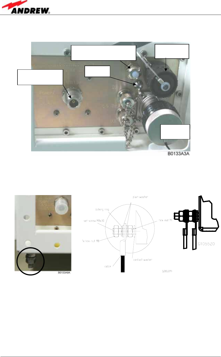
4.2.2. Connections
figure 4-3 Connector flange
4.2.3. Grounding
figure 4-4 Grounding bolt
Grounding must be carried out. Connect an earth bonding cable to the grounding
connection provided at the outside of the remote unit (see figure 4-3 Connector
flange). Do not use the grounding connection to connect external devices.
After loosening the hex nut, connect the earth bonding cable between the two
washers as illustrated in figure 4-4 Grounding bolt. Then, fasten all parts again with
the hex nut.
LED
Mains
connector
N-connector
mobile / antenna
Optical
connector
Cable gland (e.g. for
external alarms cable)
4 Installation
ID No: 163511 Page 19
4.2.4. Power Connection
Before connecting electrical power to the units, the system must be grounded as
described in the previous chapter.
Mains power must be connected at the mains connector of the unit (see figure 4-3
Connector flange).
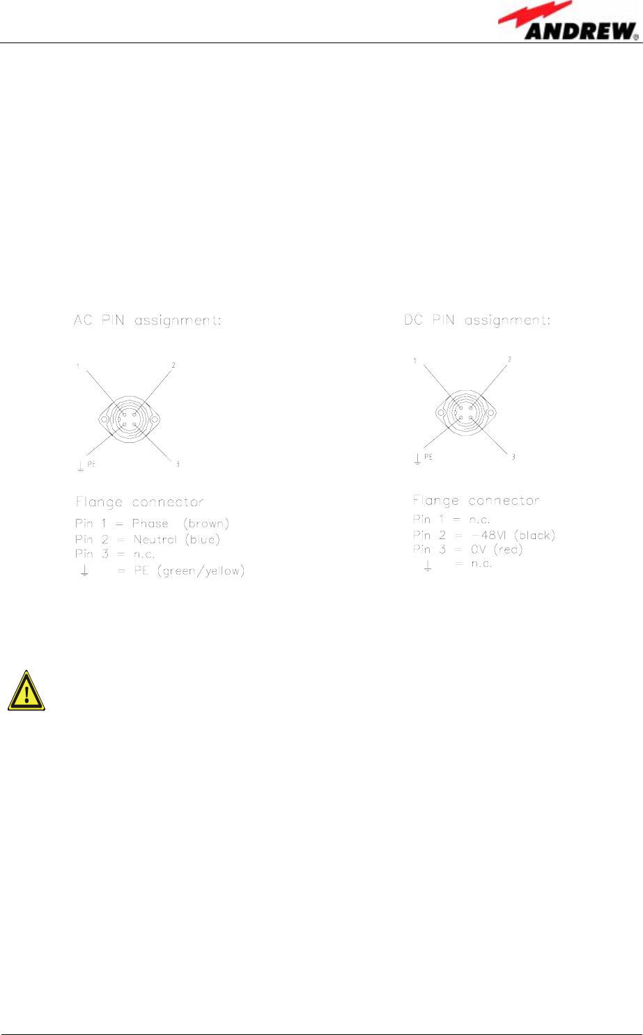
The power supply plug is part of the delivery. The correct wiring of the power supply
plug is as follows:
G1055Z0
G1055Z0
figure 4-5 AC mains plug figure 4-6 DC mains plug
For the AC power supply connection, a minimum cross section of 1.5
mm2 is required and for the DC power supply connection, a minimum
cross section of 2.5 mm2 is required. Each wire must observe the
applicable national regulations regarding loop impedance, voltage drop,
and methods of installation. Make sure to connect the correct voltage to
the unit.
) Note: Do not connect or disconnect the power cord at the mains connector
while power is on. Turn off mains* power before connecting the
power cord at the remote unit, then, engage mains again.
* Mains power must be interrupted with an external mains breaker. For the mains
breaker, observe the following recommendation:
120 Volt / 20 Amp max. or 240 Volt / 16 Amp, single-phase, 50/60 Hz AC service is
needed, i.e. the external AC breaker should be 20 Amps max. for 120-Volt service or
16 Amps for 240-Volt service.
For the DC power supply, observe the local regulations of the DC service provider.
User’s Manual for Remote Unit
MMR8L L
Page 20 M0106ASB.doc
4.2.5. Connection of the Antenna Cables
The remote unit has an N-type antenna connector or can be delivered with a 7/16
adapter. For its location please refer to figure 4-3 Connector flange. For mounting the
cable connectors, it is recommended to refer to the corresponding documentation of
the connector manufacturer. The bending radius of the antenna cables must remain
within the given specifications.
For the selection of cable and antenna it should be considered that a cable with
higher loss is less expensive but on the other hand it impairs performance.
It is sufficient to tighten the N-type (or 7/16) antenna connectors hand-
tight. The use of a tool (like pliers) may cause damage to the connector
and, therefore, lead to a malfunctioning of the remote unit.
4.2.6. Optical Fibre Cable Connection
In case of a backbone structure it has to be guaranteed that there is a
minimum wavelength difference of 20 nm. This will be guaranteed by
using four different optical interfaces with four different wavelengths
according to ITU grid. Thus, there are also four different remote units.
In one optical backbone, each type of unit can only be used once!
Rules for optical fibre connection
Optical signals are transmitted by use of optical fibres. When connecting these fibres
observe the following instructions.
) Note: Care should be taken when connecting and disconnecting fibre
optic cables. Scratches and dust significantly affect system
performance and may permanently damage the connector. Always
use protective caps on fibre optic connectors not in use.
In general optical fibres do not need special protective measures. However,
protection against environmental influences e.g. rodents and humidity must be
considered.
The optical fibre is a single mode fibre. Type is E9/125µm with the following minimum
requirements.
Attenuation: <0.36 dB/km @ 1310 nm / <0.26 dB/km @ 1550 nm
Dispersion: <3.5 ps/nm km @ 1310 nm / <18.0 ps/nm km @ 1550 nm

4 Installation
ID No: 163511 Page 21
The specified bending radius of the optical fibres must not be exceeded. The pigtails
for the connection between mini master and remote unit must have a sufficient
length. A protection for the feeding into units must be given. For MMR8L L the
system attenuation of the optical fibres, including the connectors, must not exceed
10 dB.
System attenuation and attenuation of optical components must be determined. This
can be achieved by measuring attenuation and reflection with an appropriate
measuring instrument. For pigtails, a total value of < 0.4 dB (measured to a reference
plug) can be assumed due to the dead zone of the reflectometer. These
measurements must be made with a sufficient length of optical fibre, at the in- and
output of the device which has to be measured.
Fibre cable connectors have to be of the same type (E2000APC) as the connectors
used for the unit. The fibre optic cables are connected to the optical transceiver.
) Note: Angled connectors are not compatible with straight optical
connectors; non-compatibility of connectors will result in
permanent damage to both connectors.
Before connecting the fibre cables, follow the procedure below to ensure optimized
performance. It is important that these procedures are carried out with care:
¾ Remove fibre optic protective caps.
¾ Do not bend the fibre optic cable in a tight radius (< 4 cm) as this may cause
cable damage and interrupt transmission.
¾ Using high-grade alcohol and lint-free cotton cleaning swabs, clean the end of
the fibre optic cable that will be inserted in the optical connectors on the donor
interface box.
¾ Blow out the laser receptacle with clean and dry compressed air to remove
any particulate matter.
¾ Connect the fibre optic cables by inserting the cable end into the laser
receptacle and aligning the key (on the cable end) with the keyed slot.
¾ Do not use any index matching gels or fluids of any kind in these connectors.
Gels are intended for laboratory use and attract dirt in the field.
User’s Manual for Remote Unit
MMR8L L
Page 22 M0106ASB.doc
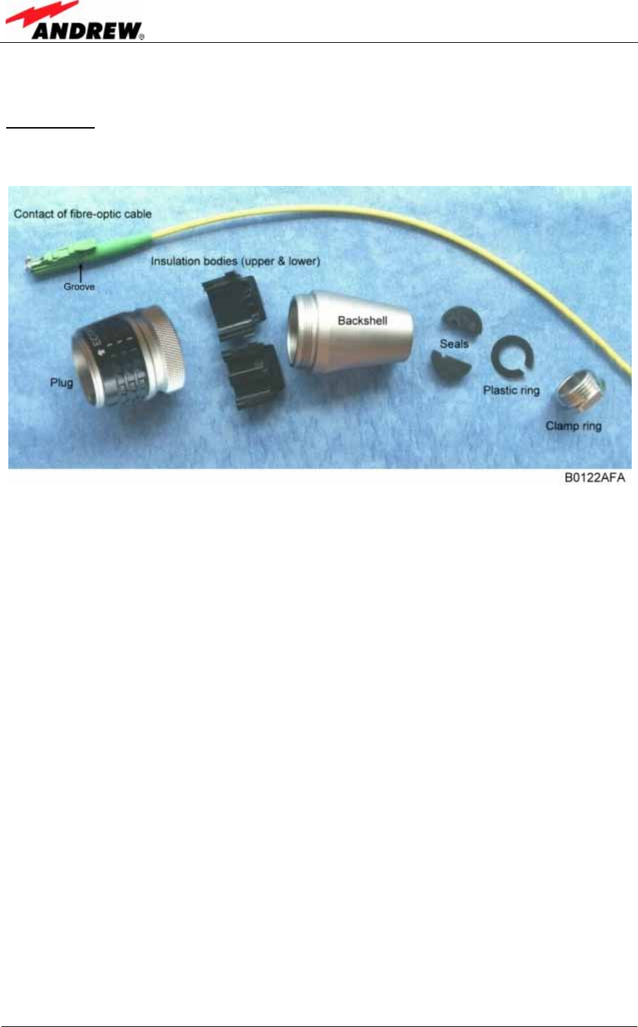
4.2.6.1. Protective Plug
Connection:
A protective plug is provided for the connection of the fibre-optic cables.
figure 4-7 Protective plug assembly
) Note: Only high-quality connectors must be used for this type of plug.
Qualified brands are Diamond or Huber & Suhner.
4 Installation
ID No: 163511 Page 23
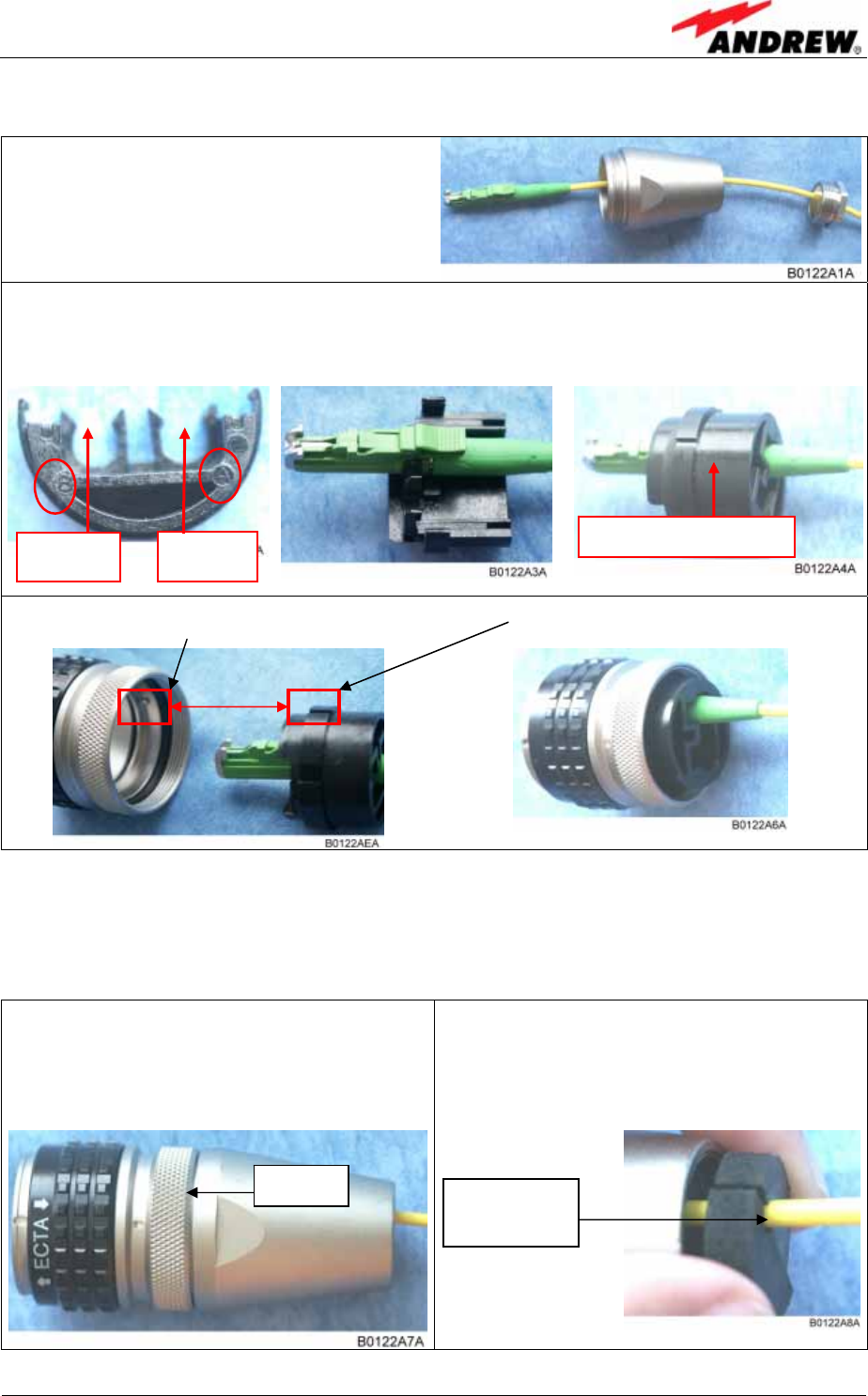
For plug assembly observe the following instruction.
1. Pass one or two contacts through the
backshell and the clamp ring.
2. Place the contact(s) on the lower insulation body by pushing the groove of the
contact into the cavity. If there is only one contact, cavity A must be used. Cavity
B is used for the diversity path.*
3. Then, mount the upper insulation body on the lower insulation body. **
4. Bring the insulator into the plug. The narrow groove of the insulator must be fitted
into the stamp of the plug.
* To release the contact for disassembling push the inner snap to the side and pull the contact out.
** To release upper and lower insulation body for disassembling, use a small screwdriver and
carefully open the snap-connections at the left and the right side of the insulator without
damaging them.
5. Fasten the insulator by screwing the
backshell tight onto it. Use a spanner
with opening 32 to screw the
backshell tight (no gap).
6. Place the appropriate seal parts (with
one groove for one contact or two
grooves for two contacts) over the
cable(s) and push them into the
backshell.
Cavity A Upper insulation body
Cavity B
Seals with
one groove
no gap
User’s Manual for Remote Unit
MMR8L L
Page 24 M0106ASB.doc
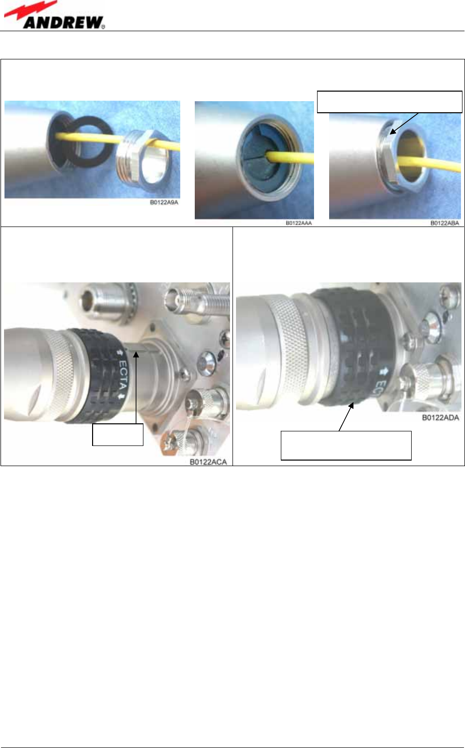
7. Bring the plastic ring over the cable(s), push it into the backshell and compress
the seals and plastic ring by screwing the clamp ring tight (no gap) using a
spanner with opening 20. ***
8. Connect the plug to the optical fibre
connector of the remote unit, again by
fitting a stamp on the plug into the
groove of the connector.
9. To lock the connector push the black
locking ring forward.****
*** For disassembling, release the clamping ring and remove the seals and the plastic ring first.
**** Locking mechanism: The system of locking the plug is based on a “push-pull” mechanism. The
locking ring has to be pushed forward to lock the connector and pulled back to free the
connection.
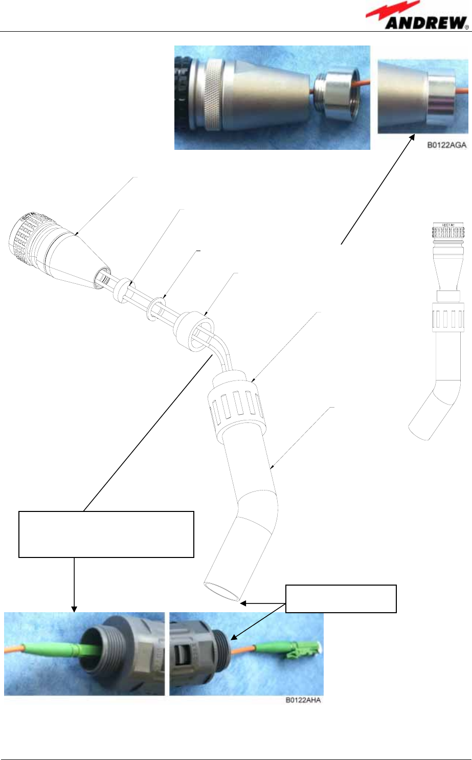
4.2.7. Protective Tube Kit
As additional protection for the optical fibres, this connector type can be
supplemented by a special tube kit. To fasten the tube correctly, first unscrew the
clamp ring (if already installed) of the original plug kit.
Then, proceed according to the following instruction:
Groove Push forward to lock, pull
back to free connection
Screw tight till gap is closed
4 Installation
ID No: 163511 Page 25
Scr ew t he reducer t o
t he prot ect ive plug
backshell wit hout gap.
Place t he appr opriat e seal
par t s (wit h) one groove f or
one cont act or t wo grooves
f or t wo cont act s) over t he
cable(s) and push t hem into
t he backshel l.
G1055M0
pr ot ect ive plug
f ibr e cable
r educer
coupling
pr ot ect ive t ube
plast ic ring
figure 4-8 Tube kit installation
Push the fibre optic cable
carefully through the tube until
it comes out at the other end.
Other end of tube

User’s Manual for Remote Unit
MMR8L L
Page 26 M0106ASB.doc
For your notes:

5 Commissioning
ID No: 163511 Page 27
5. COMMISSIONING
5.1. GENERAL
Read the health and safety warnings in chapter 1.2 Health and Safety Warnings as
well as the description carefully to avoid mistakes and proceed step by step as
described!
• Do not operate the remote unit without terminating the antenna connectors.
The antenna connectors may be terminated by connecting them to their
respective antennas or to a dummy load.
• Only qualified personnel should carry out the electrical, mechanical,
commissioning and maintenance activities that require the unit to be powered
on when open.
• When opening the remote unit do not damage the warranty labels on the
internal devices. The warranty is void if the seals are broken.
• Ensure that all connections have been performed according to chapter 4.2.2
Connections.
5.2. AUTO-LEVELLING
For a proper operation of the auto-levelling function, a defined level has to be set at
the optical interface (DL) of the master unit. For details refer to the software manual
of the master unit.

User’s Manual for Remote Unit
MMR8L L
Page 28 M0106ASB.doc
For your notes:

6 Alarms
ID No: 163511 Page 29
6. ALARMS
6.1. BITE AND ALARMS
The Built-In Test concept comprises the monitoring of the power supplies, the power
amplifiers and the optical interface.
All occurring alarms can be checked via software at the master unit.
6.2. HANDLING OF ALARMS
As soon as the software acknowledges a valid alarm, a message is transmitted to the
master unit.
If the reason for the alarm has been cleared or if the alarm should continue, a new
alarm message will not be repeated. If there was an interruption of at least five
seconds after acknowledgement, a new alarm message will be generated.
6.3. ALARM STATUS
For details refer to the corresponding software documentation of the Master Unit.
User’s Manual for Remote Unit
MMR8L L
Page 30 M0106ASB.doc
6.4. LED ALARMS
For local supervision, a LED on the connector flange of the remote unit gives an
indication of possible reasons for alarms. This table shows possible on-site measures
that could be checked before referring to the master unit alarm list.
LED Indication Alarms Possible on-site measures
Green No alarm Æ
Status ok
Door alarm Close the door (RUs with door).
Alarms not directly related to RU:
External alarms Check externally connected devices.
Optical alarm Rx
Check fibre loss of optical link.
Check optical connectors.
Clean optical connectors.
(MU: Check optical output power of
corresponding OTRx at master unit).
Orange
ALC alarm (MU: Decrease DL input power of affected
band).
Alarms directly related to RU:
Power 28V Change power supply (RUs with door).
Replace the affected remote unit.
Temperature Reduce environmental temperature.
Eliminate thermal short circuit.
Fan Disconnect and connect mains. Fans should
run briefly (SW version > 2.4). If not, replace
the fans at RU.
I²C Disconnect and connect mains.
Optical alarm Tx -
Red
A
mplifier “Power
Down” (MU: Change amplifier setting at MU
controller).
LED off Mains
Check power switch inside of RU (RUs with
door).
Check mains cabling.
Check mains power.
table 6-1 LED alarms
For the position of the LED see chapter 6.4 LED Alarms.
Explicit troubleshooting is available in the MU software, (software manual or WEB
Interface).
6 Alarms
ID No: 163511 Page 31
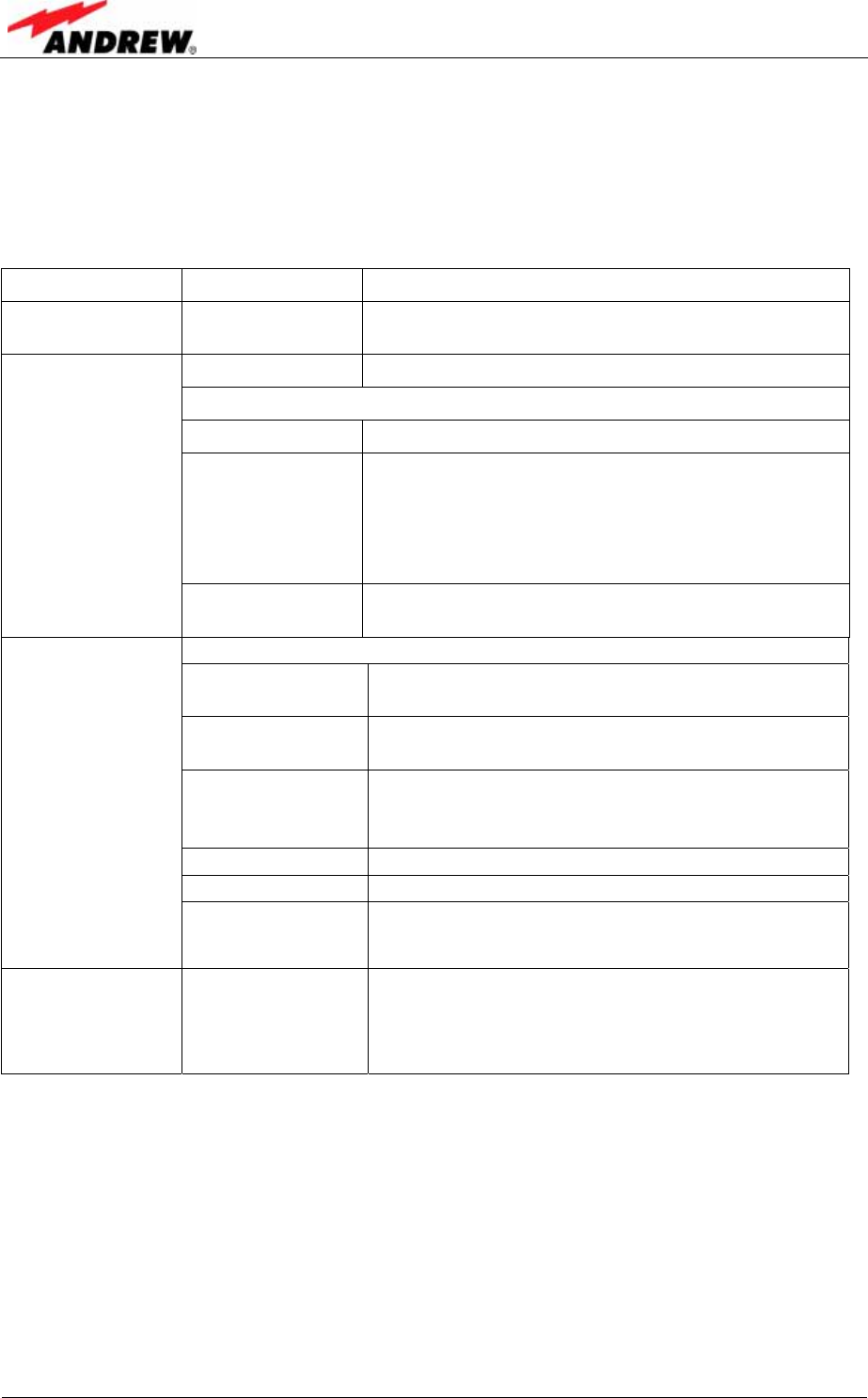
6.5. EXTERNAL ALARM INPUTS AND OUTPUTS
There are four alarm inputs and four alarm outputs. The alarm outputs (open
collector output 5 V / 1 mA) are normally low. In case of an alarm they are high active
(5V). They can be used to monitor alarms with an external alarm indicator. Each
alarm output can be set individually to any alarm at the Remote Unit. For details
please refer to the according chapter in the software manual of the Master Unit.
) Note: The manufacturer/ supplier of this system accepts no liability for
damage caused by equipment connected to external outputs or by
effects from such equipment.
With the external alarm inputs, it is possible to monitor the status of connected
devices, e.g. a UPS, via software. All alarm inputs are normally high (5V) without
connection.
The device to be monitored must be connected so that the alarm contacts (contact
on the right is always GND) will be closed in case of an alarm (I max = 8 mA). The
alarm inputs are potential-free with common ground.
For the location of the external alarm inputs and outputs refer to figure 6-1
Connecting board. Settings have to be done via the MMR Master Controller and are
described in the according software documentation.
figure 6-1 Connecting board

User’s Manual for Remote Unit
MMR8L L
Page 32 M0106ASB.doc
6.6. TROUBLESHOOTING
The status of the remote unit can be checked via the MMR Master Unit (for details
please refer to the software manual of the MMR Master Controller). Locally, the
status can be checked at the LED, see chapter 6.4 LED Alarms.

7 Maintenance
ID No: 163511 Page 33
7. MAINTENANCE
7.1. MAINTENANCE
Read the health and safety warnings in chapter 1.2 Health and Safety Warnings.
) Note: The remote unit does not require preventative maintenance
measures.
Maintenance of the MMR8L L should be performed on a FRU (Field Replaceable
Unit) basis only. Do not damage the warranty labels on the components, as this voids
the warranty.
The spare parts list contains only units that can be replaced without tuning or
soldering work.
) Note: Defect parts should only be replaced by original parts from the
supplier. All interventions inside the housing are at one’s own risk.
) Note: During maintenance ensure that the unit has been disconnected
from mains.
To open the cabinet of the MMR8L L, observe the instructions in chapter 4.1.1
General.
) Note: Before disconnecting any cables, label any unlabeled cables to
ensure correct reconnection.
To replace an FRU, use the appropriate tools. Replacement tools may be ordered
from the supplier. All screws have a right-hand thread, turn the tool clockwise for
tightening and anti-clockwise for loosening.
SMA connectors have a specified torque of 100 Ncm. Use an appropriate tool to
fasten and unfasten these connectors. Do not over-tighten the connectors or screws.
The table below shows various screws with their respective torques.
Screw Type Tallow-drop Socket head cap Countersunk head
Thread size Specified Torque (in Ncm)
M 2.0 40 not in use 40
M 2.5 82 not in use 82
M 3.0 145 100 145
M 4.0 330 330 330
M 5.0 650 tbd. 650
table 7-1 Specified torques for various screw types
) Note: Do not forget to reinstall the front cover after the replacement
procedure to ensure safe operation.
If any FRU not contained in the following chapter needs to be replaced, contact
customer service for additional instructions.
User’s Manual for Remote Unit
MMR8L L
Page 34 M0106ASB.doc
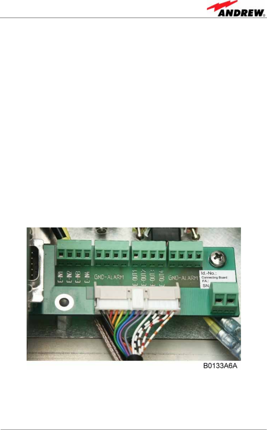
7.2. GENERAL
• To open the cabinet of the remote unit, first
dismount the locker by unlocking it with the key
(which is part of the delivery) and pulling it out
carefully.
figure 7-1 Locker with key
figure 7-2 Front and top
cover screws
• Then remove the front cover by loosening the
four M5 socket head cap screws (circle-marked
in figure 7-2 on the left). Do not remove those
screws. When they are loosened, the front cover
can be taken off.
• To open the cabinet, unscrew the three M5
socket head cap screws (captive) of the top
cover of the remote unit.
figure 7-3 Position of mains
power switch
• Set the mains power switch inside to On (I):
• Close the cabinet.
) Note: Do not forget to reinstall the front cover
afterwards to ensure safe operation.
• Check the status of the LED. Ensure it is showing
a green light.
Three top
cover
screws
Locker
Front
cover
Mains
power
switch
7 Maintenance
ID No: 163511 Page 35
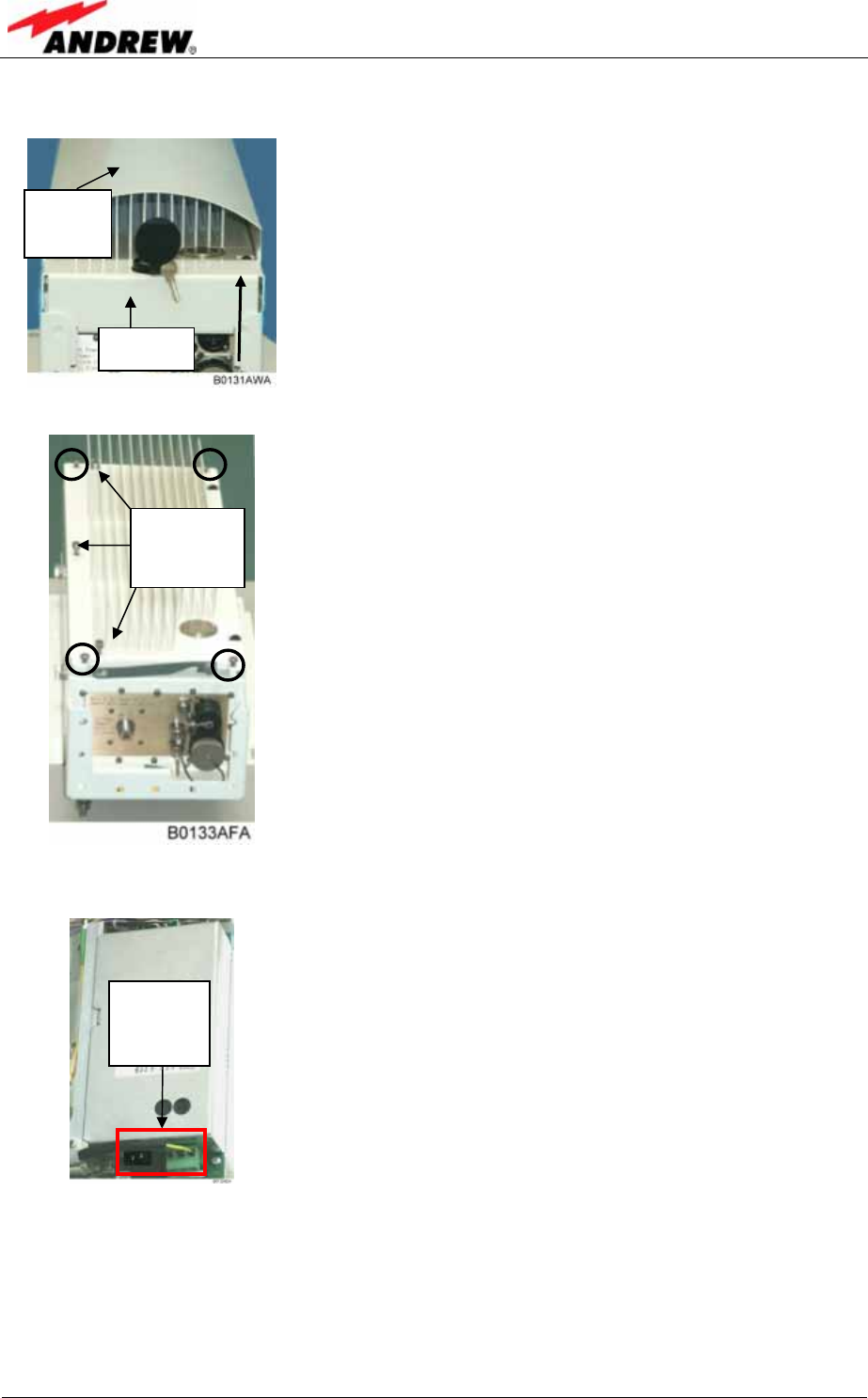
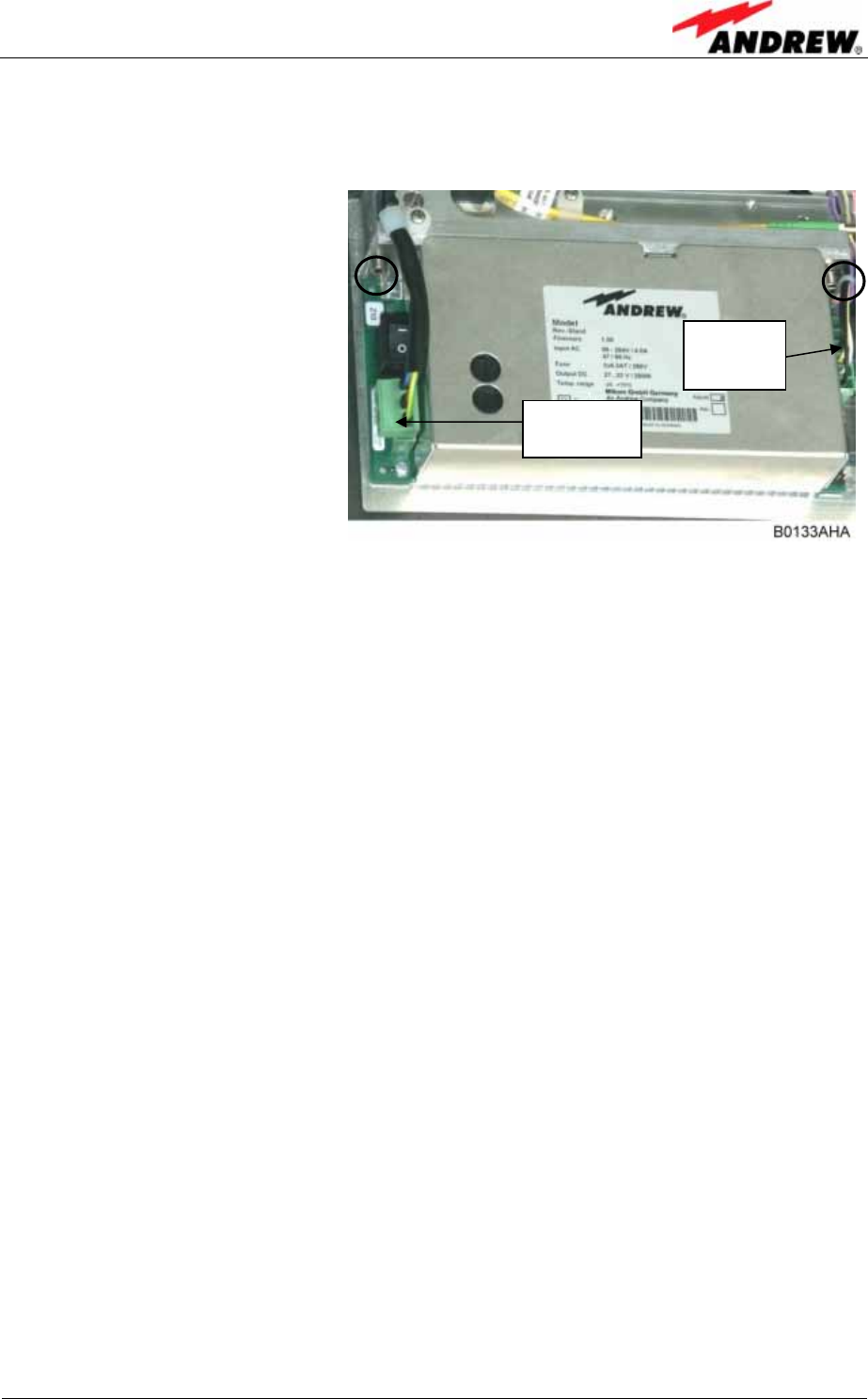
7.3. REPLACEMENT OF POWER SUPPLY
• To remove a power supply,
first disconnect mains,
mains cable and DC cable.
• Unscrew the hexagon
socket head cap screw on
the left-hand side and
loosen the other socket
head cap screw on the
right-hand side (circle-
marked) with an Allen key.
• Pull the power supply out.
• Apply heat-conducting
paste to the mounting
surface of the new power
supply.
• Carefully insert the new
power supply.
• Fasten the two socket
head cap screws.
• Reconnect all cables.
figure 7-4 Power supply screws
Mains
connector
DC con-
nector

User’s Manual for Remote Unit
MMR8L L
Page 36 M0106ASB.doc
For your notes:
8 Appendix
ID No: 163511 Page 37
8. APPENDIX
8.1. LAYOUT
figure 8-1 Layout of the remote unit
User’s Manual for Remote Unit
MMR8L L
Page 38 M0106ASB.doc
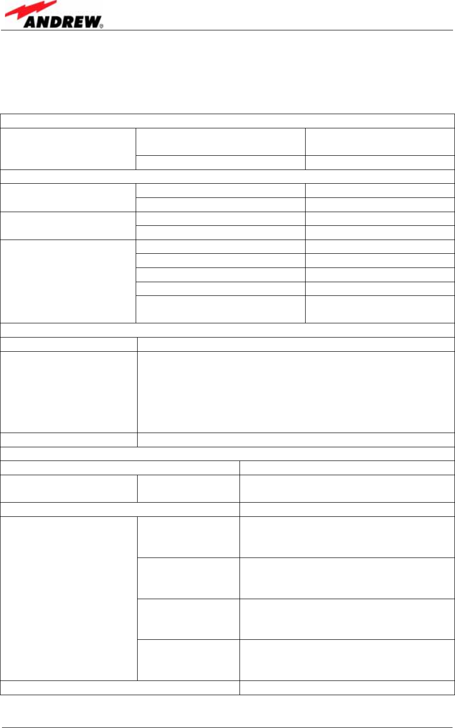
8.2. SPECIFICATIONS
8.2.1. Electrical Specifications
MMR8L L
Mains power 100 to 240 Vac
36 to 72 Vdc
Power Supply Power consumption 180 W
Interface
Number of connectors 1 single duplexed RF port
BTS Interface Input power Micro: 33/43 dBM typical
Connector N Female or DIN 7/16
Antenna Port Return loss 15 dB
Connectors E2000/APC 8°
Optical return loss 45 dBm minimum
Fiber type Single mode E9/125 µm
Optical link budget 0 to 10 dB
Optical link
Composite input power @
OTRX master side +4 dBm maximum
System supervision and control
Commands RF on/off; External control ports
Alarms Summary
Power supply
Optical UL and DL failure
RF UL and DL failure
Temperature
Door open
Supervision Composite output power
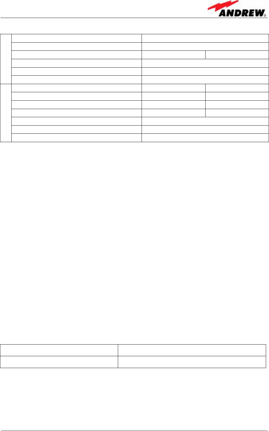
Frequency ranges
Nominal 20 dB Bandwidth 51 MHz
800 MHz band LMR UL: 806 to 824 MHz
DL: 851 to 869 MHz
Mean rated output power 1) 40 dBm
@ 1 carrier 40 dBm 3) Analog; 40 dBm 3) iDEN;
40 dBm TDMA/ EDGE; 40 dBm 3)
CDMA; 38 dBm 3) WCDMA
@ 2 carriers 37 dBm 3) Analog; 37 dBm 3) iDEN;
37 dBm 3) TDMA/ EDGE;
35 dBm 3) CDMA; 35 dBm 3) WCDMA
@ 4 carriers 34 dBm 3) Analog; 34 dBm 3) iDEN
34 dBm 3) TDMA/ EDGE;
32 dBM 3) CDMA; 32 dBm 3) WCDMA
Output power 2)
@ 8 carriers 31 dBm 3) Analog; 31 dBm 3) iDEN
31 dBm 3) TDMA/ EDGE
29 dBm 3) CDMA; 29 dBm 3) WCDMA
Intermodulation distance -60 dBc
8 Appendix
ID No: 163511 Page 39
Output tolerance over frequency ± 1.0 dB
Output tolerance over temperature ± 1.0 dB
ICP3 optimized 4) NF optimized
4)
Gain 5) +33 dB
Gain @ remote unit 6) 58 dB
D
L
Output impedance 50 Ohms
ICP3 optimized 4) NF optimized
4)
Input ICP3 +1.5 dBm -9 dBm
Noise figure (NF) 7) 13.5 dB 6.0 dB
Gain 5) 33 dB 45 dB
Gain @ remote unit 6) 70 dB
Automatic Level Control (ALC) factory set
U
L
Input impedance 50 Ohms
1) Mean rated output power specified for signals with 0 dB peak to average signals.
Note: The manufacturer' s rated output power of this equipment is for single carrier
operation. For situations when multiple carrier signals are present, the rating would have
to be reduced by 3.5 dB, especially where the output signal is re-radiated and can cause
interference to adjacent band users. This power reduction is to be by means of input
power or gain reduction and not by an attenuator at the output of the device.
2) Spurious < -13 dBm @ 1 MHz RBW / -73 dBm @ 1 Hz RBW
3) All dB and dBm figures are typical values.
4) 0 to 10 dB optical loss
5) Gain calculation from reference point A to B, auto-levelling active (gain range software
adaptable )
6) Auto-levelling not active
7) Note: The noise figure (NF) stated above refers to one Remote Unit (RU) per sector. The
NF system increases with the number of the RUs per sector. It is recommended not to
operate above four RUs per sector. With four RUs per sector, the system NF will be
increased by 6 dB.
All data is subject to change without notice!
8.2.2. Environmental and Safety Specifications
) Note: For detailed information, please refer to the Environmental and
Safety Specifications leaflet of the supplier, related to ETS 300 019
(European Telecommunication Standard).
Operating temperature range -33° C to +50° C
Ingress protection IP66
All data is subject to change without notice!
User’s Manual for Remote Unit
MMR8L L
Page 40 M0106ASB.doc
8.2.3. Mechanical Specifications
) Note: The unit is mounted directly to the wall or pole. Vertical mounting,
and a spacing of 300 mm (11.8’’) above and below is required. Do
not block air inlet and outlet.
Height, width, depth 546 x 190 x 260 mm (21.5 x 7.5 x 10.25 inch)
Weight 16 kg (35 lb)
All data is subject to change without notice!
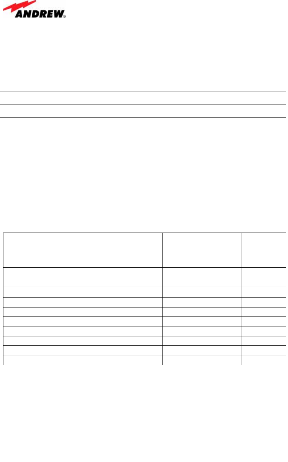
8.3. PARTS LIST
The following lists contains all parts available for the remote unit. The configuration of
the delivered unit meets the requirements of the customer and can differ depending
on the state of the delivery.
Parts List of the Remote Unit MMR8L L
Designation: ID No FRU
MMR8L L 163506
Control Unit populated Board 1570.5 156470
Cover 160736
x
DC/ DC converter 28V/ 12V 0.7A 163549
Dpx UL-aktiv 806-824 851-869 162326
Fin.Ampl. 82W 851-869 36dB 161175
Locker 160734
x
OTRx 8RU 163500
Power Supply Unit DC IN 48V 161751 x
User's Manual for MMR8L L 163511
Pole Mounting Kit for K-/ L-/ Q-Cabinet 163746 x
Wall Mounting Kit 162809 x
The manufacturer reserves the right to replace the spare parts listed above by
equivalent substitutes!

9 Index
ID No: 163511 Page 41
9. INDEX
A
Abbreviations............................................5
Address of Mikom.....................................8
Alarms
Alarm Status..............................................29
Bite and Alarms.........................................29
External Inputs ..........................................31
Handling of Alarms....................................29
LED ...........................................................30
List.............................................................32
Outputs......................................................31
RU .............................................................32
B
Block Diagram........................................13
C
Commissioning.......................................27
Components
Interior .......................................................14
Connection Rules
Optical Fibre Cables..................................20
Optical Fibres ............................................20
Connections
Antenna.....................................................20
Connector Flange......................................18
Optical Fibre Cable ...................................20
Power ........................................................19
E
External Inputs .......................................31
G
Grounding...............................................18
H
Health and Safety Warnings.....................6
I
Installation
Electrical ................................................... 17
Mechanical ............................................... 15
International Contact Addresses ..............9
L
Layout.....................................................37
Levelling .................................................27
M
Maintenance...........................................33
Mounting
General..................................................... 15
Wall........................................................... 16
O
Optical Fibre Connection
Protective Plug ......................................... 22
Protective tube kit..................................... 24
Outputs...................................................31
P
Parts List ................................................40
Power Supply
Replacement ............................................ 35
Preamble..................................................8
R
Replacement of
Power Supply ........................................... 35
S
Specifications
Electrical ................................................... 38
Environmental and Safety ........................ 39
Mechanical ............................................... 40
T
Troubleshooting......................................32
