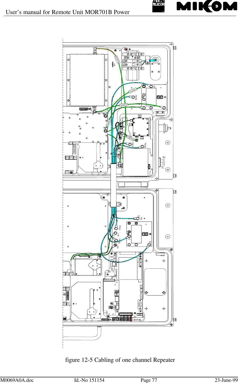
Andrew Wireless Innovations Group RPT-MOR701 PCS Repeater User Manual M0069A0A

Andrew Wireless Innovations Group PCS Repeater M0069A0A

User Manual

User’s manual for Remote Unit MOR701B PowerM0069A0A.doc Id.-No 151154 Page 123-June-99User’s manual forband or channel selective Remote UnitMOR701B Power(Id.-Nos.: 147362/148669)Author: Approved: QA:
User’s manual for Remote Unit MOR701B PowerM0069A0A.doc Id.-No 151154 Page 223-June-99Table of ContentsLIST OF UNIT SPECIFIC ABBREVIATIONS 6CONTENTS OF DELIVERY 9HEALTH AND SAFETY WARNING  10PREAMBLE 111INTRODUCTION 131.1 Intended purpose 131.2 About the MOR701B POWER 132FUNCTIONAL DESCRIPTION 142.1 General 152.2 RF modules 152.3 Mother board 172.4 Control module SM 2009 182.5 Duplexer 192.6 Active Combiner 202.7 Transceiver MFY1319 202.8 FSK modulator 212.9 4-way-Splitter 222.10 Measuring aids 222.11 Power supply 222.12 Feed forward amplifier 24
User’s manual for Remote Unit MOR701B PowerM0069A0A.doc Id.-No 151154 Page 323-June-993FUNCTIONS AND FEATURES 253.1 Band and channel selectivity 253.2 Gain setting 253.3 ALC 263.4 BITE and alarms 263.4.1 Handling of alarms 283.4.2 Status report 293.4.3 Severity levels 304OPTIONAL EQUIPMENT 324.1 VSWR module 324.2 External alarms 324.3 Battery backup module 345SPECIFICATION 365.1 Electrical specification 365.2 Optical specification 385.3 Mechanical specification 385.4 Environmental and safety 385.5 External electrical interfaces 395.5.1 Electrical power 395.5.2 RF connection 405.5.3 Optical connector 406INSTALLATION 416.1 Mechanical installation426.2 Electrical installation 456.2.1 Grounding 456.2.2 Power connection 466.2.3 Connection of the antenna cable 466.2.4 Connecting fibre optic cables 47
User’s manual for Remote Unit MOR701B PowerM0069A0A.doc Id.-No 151154 Page 423-June-997SETTING TO WORK 497.1 Preparation 497.2 Setting of operational parameters 507.2.1 Manual setting of the attenuation by means of rotary switches 507.2.2 Settings via personal computer as terminal 527.2.3 Remote control via Master Unit 548TROUBLE SHOOTING 558.1 Error indication 551.2 Boot process 551.3 Alarm monitoring with the STATUS HIST command 561.4 Power supply 561.5 General remarks 569MAINTENANCE 579.1 General 579.2 Replacement of the fuses (mains) 579.3 Replacement of the power supply fuse 589.4 Replacement of the mains cable 589.5 Replacement of the RAM / RTC battery 599.6 Replacement of the dummy battery backup module 609.7 Replacement of the duplexer 619.8 Replacement of RF modules 629.9 Replacement of the control module SM 2009 649.10 Replacement of power supplies 659.11 Replacement of Active Combiner modules 669.12 Replacement of feed forward amplifier 679.13 Replacement of the FSK modulator 69
User’s manual for Remote Unit MOR701B PowerM0069A0A.doc Id.-No 151154 Page 523-June-999.14 Replacement of the Transceiver MFY1319 6910 SPARE PARTS LIST 7011 CONFIGURATION LIST7212 APPENDIX 7312.1 Installation drawing of the Repeater 7312.2 Top view of the Repeater (left-hand side , four channel configuration) 7412.3 Top view of the Repeater (right-hand side, four channel configuration) 7512.4 One channel configuration –block diagram and cabling 7613 INDEX 78
User’s manual for Remote Unit MOR701B PowerM0069A0A.doc Id.-No 151154 Page 623-June-99LIST OF FIGURES AND TABLEStable 1-1 List of international sales offices............................................................................12figure 2-1 Block diagram of MOR701B Power.....................................................................14figure 2-2 Top view of an RF module...................................................................................16figure 2-3 Top view of a mother board .................................................................................17figure 2-4 Top view of the control module............................................................................18figure 2-5 Top view of the duplexer......................................................................................19figure 2-6 Top view of an Active Combiner module.............................................................20figure 2-7 Transceiver MFY1319 .........................................................................................20figure 2-8 Installation position of the Transceiver.................................................................21figure 2-9 Configuration of the connecting pins....................................................................21figure 2-10 Top view of the 4-way-Splitter (Transceiver dismounted) ..................................22figure 2-11 Mounting position of power supplies..................................................................23figure 2-12 ON / OFF position of external switch.................................................................24figure 2-13 Top view of the feed forward amplifier ..............................................................24figure 3-1 Position of rotary switches ...................................................................................25figure 3-2 Position of failure LEDs.......................................................................................26figure 3-3 Status hist report ..................................................................................................27table 3-4 List of all available alarms .....................................................................................28figure 3-5 Example of a GET1 report ...................................................................................29figure 3-6 Example of a STATUS report ..............................................................................30figure 4-1 Clamps for external alarms...................................................................................32figure 4-2 Cable configuration and installation position........................................................34figure 4-3 Mounting position of batteries..............................................................................35figure 5-1 Screw terminal for mains cable ............................................................................39figure 5-2 Connector panel layout ........................................................................................40figure 6-1 System description...............................................................................................41figure 6-2 Wall mounting brackets .......................................................................................43figure 6-3 Clearance distance................................................................................................44figure 6-4 Grounding kit.......................................................................................................45figure 6-5 Screw terminal .....................................................................................................46table 7-1 LED indication ......................................................................................................49figure 7-2 Position of the DIP-Switch 1................................................................................50figure 7-3 Position of the rotary switches..............................................................................51figure 7-4 Rotary switches and label.....................................................................................51table 7-5 DIP-switch configuration.......................................................................................52figure 7-6 DIP-switch 2 for local mode.................................................................................52figure 9-1 Top view of the Repeater .....................................................................................57figure 9-2 Fuse terminal .......................................................................................................58figure 9-3 Position of power supply fuse...............................................................................58figure 9-4 Position of  RAM/RTC battery.............................................................................60figure 9-5 Position of dummy battery backup module...........................................................61figure 9-6 Cable configuration of the duplexers....................................................................61figure 9-7 Connector panel layout ........................................................................................62figure 9-8 Top view of an RF module...................................................................................63
User’s manual for Remote Unit MOR701B PowerM0069A0A.doc Id.-No 151154 Page 723-June-99figure 9-9 Position of hex coded rotary switches...................................................................64table 9-10 Address of synthesizer .........................................................................................64figure 9-11 Position of control module .................................................................................65figure 9-12 Power supply......................................................................................................65figure 9-13 Position of special-nut M4..................................................................................66figure 9-14 Position of counter sunk screws on Active Combiner .........................................67figure 9-15 Position of the feed forward amplifier reset board ..............................................68figure 9-16 Position of feed forward amplifier (Right-hand side of Repeater).......................68figure 9-17 FSK modulator...................................................................................................69figure 9-18 Installation position............................................................................................69table 10-1 Spare parts list .....................................................................................................71figure 11-1 Sample of a configuration list.............................................................................72figure 12-1 Installation drawing of the Repeater...................................................................73figure 12-2 Top view of the Repeater (left-hand side, four channel configuration)................74figure 12-3 Top view of the Repeater (right-hand side, four channel configuration)..............75figure 12-4 Block diagram of one channel Repeater .............................................................76figure 12-5 Cabling of one channel Repeater........................................................................77
User’s manual for Remote Unit MOR701B PowerM0069A0A.doc Id.-No 151154 Page 823-June-99LIST OF UNIT SPECIFIC ABBREVIATIONSALC Automatic Level ControlBCCH Broadcast Control ChannelBITE Built In Test EquipmentBTS Base Transceiver StationDL DownlinkETS European Telecommunication StandardFFwd Feed Forward AmplifierFSK Frequency Shift KeyingId.-No. Ident NumberI²C-Bus  Inter Integrated Circuit Bus ( Philips )LMT Local Maintenance TimeoutMFY MIKOM TransceiverMOR MIKOM Optical RepeaterOMC Operation and Maintenance CentrePABX Private Automatic Branch ExchangePCMCIA Personal Computer Modem Communication International AssociationPSTN Public Switched Telephone NetworkRev RevisionRF Radio FrequencyRLP Radio Link ProtocolRSSI Receive Signal Strength IndicationRTC Real Time ClockSDA Serial Data Line of I²C-BusSCL Serial Clock Line of I²C-BusUL UplinkUPS Uninterruptable Power SupplyVSWR Voltage Standing Wave Ratio
User’s manual for Remote Unit MOR701B PowerM0069A0A.doc Id.-No 151154 Page 923-June-99CONTENTS OF DELIVERYQty 1Repeater MOR701B PowerQty 1User’s manual for Repeater MOR701B PowerQty 1Set of test protocols consisting of an electrical acceptance test protocoland a safety test protocol applying to the power supplyQty 1Spare parts kit containing:- 1 control cable RS232,- 1 hex socket key, size 2.5- 1 Torx key- 5 socket head cap screws M3.0 x 30- 2 tallow-drop screws TRX M5.0x25- 2 tallow-drop screws M2.0x6- 2 tallow-drop screws M3.0x5- 4 straight pins 3.0 x 25- 3 captive washers for M5- 4 Tyraps- 3x5g Silicon heat conducting paste- 1 hex socket screw key , size 4, long- 4 nuts- 2 fuses 8 A type MT- 5 socket head cap screws M3.0x20- 2 countersunk head screw M3.0x20- 4 special nuts M4Qty 1Wall mounting kit- 2 mounting brackets- 4 washers for M8- 4 socket head cap screws M8.0x16- 2 tire boltsQty 1Wall mounting sheet
User’s manual for Remote Unit MOR701B PowerM0069A0A.doc Id.-No 151154 Page 10 23-June-99HEALTH AND SAFETY WARNINGSF Note: The electrical installation has to be performed in accordance with the safetyregulations of the local authorities. Due to safety reasons the electricalinstallation must be performed by qualified personnel. The cover of this unitshould not be opened while power is applied. Subsequent installation,commissioning and maintenance activities that require the unit to bepowered with the cover open shall only be carried out by suitably qualifiedpersonnel.F Note: The grounding of the Unit has to be performed by all means. A groundingbolt is provided at the cabinet in order to connect the earth bonding cable.F Note: The Unit is heavy-weight. Make sure that a suitable mounting surface isused. Only adequate manpower is allowed to handle the system.F Note: ESD precautions have to be observed! Before maintenance work use theavailable grounding system to connect ESD protection measures.F Note: Due to power dissipation the Repeater may heat up the air volume inside thecabinet and reach a very high temperature. Therefore the Repeater must bemounted in the vertical plane to a wall or a mast without additionalenclosure to provide sufficient ventilation. Between the housing and the walla minimum distance must be kept in order to provide air circulation.F Note: Laser radiation! Do not stare into the beam or view directly with opticalinstruments. Class 3A laser product.
User’s manual for Remote Unit MOR701B PowerM0069A0A.doc Id.-No 151154 Page 11 23-June-99PREAMBLEIn cellular systems, Repeaters are used to enhance the influence of a base station in regionswhere, due to topological conditions, poor field strengths disable communication. MIKOM isa leading manufacturer of Repeaters. They provide excellent electrical characteristics, they arelight-weight and easy to install. Hence, the MIKOM Repeater is the preferred solution.Your Repeater has been built using high reliable materials. A comprehensive qualityassurance has been applied to all fabrication steps. This secures constant quality of theproduct. Every Repeater leaves the factory only after a thorough final acceptance test,accompanied by a test certificate, which warrants perfect function. The acceptance testcertificate is subject of the delivery, and it is fixed to the Repeater lid in order to provide aquick reference for the user.Any intervention has to be performed by authorized persons only. If you need technicalassistance with the Repeater MOR701B Power approach your local sales office (see table 1-1List of international sales offices) or MIKOM directly at the following address:Under consideration of all references given in this manual, the Repeater should be taken intoservice without any complications and should operate trouble-free for a long time.MIKOM GmbHIndustriering 1086675 BuchdorfGermanyTel: +49 (0) 9099 6 90Fax: +49 (0) 9099 69 31email: sales@mikom.comhttp://www.mikom.com
User’s manual for Remote Unit MOR701B PowerM0069A0A.doc Id.-No 151154 Page 12 23-June-99LIST OF INTERNATIONAL SALES OFFICESAllen Telecom Allen Telecom (Australia)P/L Forem France30500 Bruce Industrial Parkway PO  Box 903 Z.I. des EbisoiresCleveland, Ohio 44 139-3996 Bankstown NSW 2200 78370 PlaisirUSA Australia FrancePhone: +1 ( 216 ) 349-8657 Phone: +61 ( 2 ) 9793-9644 Phone: +33-1-30-79-15-30FAX: +1 ( 216 ) 349-8408 FAX: +61 ( 2 ) 9793-9747 FAX: +33-1-30-55-55-37FOREM S.p.A. AT Singapore AT ChinaVia Archimede N. 22/24 80 Marine Parade Road CITIC Building, # 11-0520041, Agrate Brianza #19-1 Parkway Parade 19 Jiangguomenwai AvenueMilan Singapore 449269 BeijingItaly China 100004Phone: +39-39-605-41 Phone: +65-345-8022 Phone: +86-10-6508-3088FAX: +39-39-605-4477 FAX: +65-345-8033 FAX: +86-10-6508-3066AT Canada FOREM UK AT Hong Kong1815 Ironstone Manor, # 12 Unit DCastle Industrial Park 1603 Remington Certer,23 Hung to road,Pickering, Ontario L1W 3W9Canada Pear Tree LaneNewbury, Berkshire Kwun Tong, Kow LoonHong KongU.K. RG 14  2EZPhone: +1 ( 905 ) 839-3474 Phone: +44-1635-569-695 Phone: +852-2389-1844FAX: +1 ( 905 ) 839-4663 FAX: +44-1635-569-463 FAX: +852-2389-4864AT IndiaB-256 Ground Floor.Chittaranjan ParkNew Delhi 110019Phone: +91-11-696-3918FAX: +91-11-652-1648table 1-1 List of international sales offices
User’s manual for Remote Unit MOR701B PowerM0069A0A.doc Id.-No 151154 Page 13 23-June-991 Introduction1.1 Intended purposeCellular telephone systems transmit signals in two directions between base stations andmobile telephones within the signal coverage area.If weak signal transmissions occur within the coverage area because of indoor applications,topological conditions or distance from the transmitter, a Repeater is used to extendtransmission range. In the downlink path the Repeater picks up the signal from a donorantenna of an existing cell, amplifies and re-transmits it into the desired dark spot. In theuplink direction the Repeater receives signals from mobile stations present in its coveragearea and re-transmits them to the corresponding base station.1.2 About the MOR701B POWERMIKOM’s MOR701B Power Remote is available as a band selective optical repeater forGSM, CDMA and TDMA technology and as a channel selective optical repeater for CDMAand TDMA technology.A GSM channel selective version is available (MOR 740).The MOR701B Power Remote repeater bi-directionally amplifies signals between multiplemobiles and a single base station in the PCS1900 frequency band using optical fibres forinterconnection to a Master Unit. It is employed mainly in tunnels, canyons, and other areaswhere physical structures cause weak field strengths. It can provide highly selectiveamplification of band segments or channels in the PCS1900 band.The MOR701B Power Remote can be combined with other repeaters in order to create amulti-band optical repeater system. Modules operating in GSM1800, GSM900, AMPS800, oriDEN bands are available. When different modules are combined a common antenna andcontrol interface is available.The MR701 Power Remote can be set-up locally at the Master Unit through the optical fibreor remotely at the OMC. A PCMCIA slot for modem operation is an available option at theMaster Unit. The repeater has a large number of functions that can be monitored and changedby the operators via a terminal emulation program or the MIKOM OMC software platform.An easy to understand and simple to learn communication language is available to help theoperator query status reports from the repeater or to change settings.
User’s manual for Remote Unit MOR701B PowerM0069A0A.doc Id.-No 151154 Page 14 23-June-992 Functional descriptionThe Repeater MOR701B Power can be equipped from one to four bands or channels.The following block diagram shall illustrate the configuration of the system.*: one physical module contains UL and DL**: with more than two channels, the amplifier is included*** For correct cabling see Assembly Guidefigure 2-1 Block diagram of MOR701B Power
User’s manual for Remote Unit MOR701B PowerM0069A0A.doc Id.-No 151154 Page 15 23-June-992.1 GeneralThe Repeater consists of two amplifier chains. The signals to and from the mobiles arecombined to an antenna by a frequency separation unit, denominated in the following asDuplexer. The optical signals to and from the Master Unit are converted by the OpticalTransceiver.In the Downlink direction the optical signals from the Master Unit are converted into RF-signals by the Transceiver (see chapter 2.7). They pass the 4-way-Splitter (see chapter2.9),which provides the RF-signal for the RF modules. After the RF module (see chapter 2.2) theyare combined by the Active Combiner (see chapter 2.6) and afterwards amplified by the FeedForward Amplifier (see chapter 2.12), which provides the required output power. Finally thesignals are fed to the antenna by the Duplexer (see chapter 2.5).In the Uplink direction the signals from the mobiles are seperated by the Duplexer, get to aPre-Amplifier and afterwards to an RF module. The signals are combined by the ActiveCombiner then, get converted into optical signals by the Transceiver (see chapter 2.7) and arefinally transmitted to the Master Unit.In the final amplifier of the Downlink a power detection measures the output power andcontrols the gain. In the Uplink the gain is controlled by the Active Combiner to protect theOptical Transceiver. This power detection is called Automatic Level Control (ALC) (seechapter 3.3).2.2 RF modulesThe task of the RF modules is to amplify the receive signals and to convert them into anintermediate frequency. The signals, then, proceed a filter stage comprising of highly selectivefilters, and run through a digital controllable attenuator. The attenuation can be set in steps of2 dB, locally or remotely. By using the same synthesizer frequency, that was used to convertthe signals down to intermediate frequency, the intermediate frequency is mixed up to theoriginal frequency.The synthesizer is controlled via an I²C-Bus. In case of a breakdown in mains, gain andfrequency data are non-volatile stored in an EEPROM on board.See figure 2-2 Top view of an RF module for an exemplary channel or band module.
User’s manual for Remote Unit MOR701B PowerM0069A0A.doc Id.-No 151154 Page 16 23-June-99figure 2-2 Top view of an RF module
User’s manual for Remote Unit MOR701B PowerM0069A0A.doc Id.-No 151154 Page 17 23-June-992.3 Mother boardThe function of the mother board is the communication between the RF modules and thecontrol module via the I²C-Bus.In the three and four channel configuration of the Repeater there is a mother board on the left-and on the right-hand side, whereas in the one and two channel configuration there is only onemother board implemented on the right-hand side of the Repeater.Mother boards are located underneath the RF modules.figure 2-3 Top view of a mother board
User’s manual for Remote Unit MOR701B PowerM0069A0A.doc Id.-No 151154 Page 18 23-June-992.4 Control module SM 2009The control module SM 2009 is a DOS compatible micro computer. The wholecommunication between the operator and the Repeater can be done via the control module. Byusing the RS232 interface the Repeater can be controlled locally by using a VT100 terminal,or a PC emulating the VT100 terminal.Frequency and gain, power down of RF stages and ALC can be controlled and statusmessages can be received remotely via the Master Unit.The data transfer between the control module SM 2009 and the mother board is realized bythe I²C-Bus system.The I²C-Bus concept was developed by Philips for the serial connection of integrated circuitswithin one device. Two wires, SDA - serial data and SCL - serial clock, carry data betweenthe devices connected to the bus. Each device is recognized by a unique address and canoperate either as transmitter or receiver.All MOR701B Power configuration parameters are stored in an EEPROM on the controlmodule if a power supply failure occurs.figure 2-4 Top view of the control module
User’s manual for Remote Unit MOR701B PowerM0069A0A.doc Id.-No 151154 Page 19 23-June-992.5 DuplexerThe task of the duplexer is to isolate uplink from downlink, i.e. isolate transmit path fromreceive path. The pass bandwidth of the duplexer is the entire width of the uplink band andthe downlink band.Two frequency - dependent versions of the MOR701B Power are available:Id - No UL frequency DL frequency147362 1850 - 1885 MHz 1930 - 1965 MHz148669 1875 - 1910 MHz 1955 - 1990 MHzfigure 2-5 Top view of the duplexerRF probe30 dBDuplexer
User’s manual for Remote Unit MOR701B PowerM0069A0A.doc Id.-No 151154 Page 20 23-June-992.6 Active CombinerAfter passing through the RF modules, the signals will be combined by the Active Combinermodule in the UL and in the DL path. The Active Combiner will be followed by the feedforward amplifier in the DL and by the Transceiver in the UL.figure 2-6 Top view of an Active Combiner module2.7 Transceiver MFY1319The Transceiver MFY1319 is the interface between the optic and the electrical distributionunit. The function of the Transceiver is to convert the optical signal into an electrical signaland vice versa.figure 2-7 Transceiver MFY1319
User’s manual for Remote Unit MOR701B PowerM0069A0A.doc Id.-No 151154 Page 21 23-June-99figure 2-8 Installation position of the TransceiverThe configuration of the connecting pins is shown in the following figure.Pin 1 GNDPin 2 Rx Alarm normally closedPin 3 Tx Alarm commonPin 4 VccPin 5 Rx Alarm commonPin 6 Rx Alarm normally openPin 7 Tx Alarm normally closedPin 8 Tx Alarm normally openfigure 2-9 Configuration of the connecting pins2.8 FSK modulatorTo enable remote control between the Master Unit and the Remote Units a serial interface willbe implemented, in the following designated as FSK modulator. Signals from the RemoteUnit will be modulated to a 10.7 MHz carrier and are fed to the optical Transceiver to betransmitted to the Master Unit via optical vibre and vice versa.TransceiverMFY1319Optical connectorsconnecting pins
User’s manual for Remote Unit MOR701B PowerM0069A0A.doc Id.-No 151154 Page 22 23-June-992.9 4-way-SplitterThe 4-way-Splitter provides the RF-signal to the RF modules. It splits up the signal from theReceiver and provides four equal RF outputs with an attenuation of 10 dB for the RFmodules. It is mounted underneath the Optical Transceiver and can be seen only, if theTransceiver is dismounted.figure 2-10 Top view of the 4-way-Splitter (Transceiver dismounted)2.10 Measuring aidsWith the built-in RF probe test signals can be applied or detected. The duplexer is equippedwith a probe which provides a coupling factor of 30 dB. This facilitates measurements underall operational conditions, while an antenna or a dummy load may be connected.The position of the coupler on the duplexer is shown in figure 2-5 Top view of the duplexer.2.11 Power supplyFor the MOR701B Power three power supplies are necessary.Power supplies are available with different mains power. See list below for available powersupplies.
User’s manual for Remote Unit MOR701B PowerM0069A0A.doc Id.-No 151154 Page 23 23-June-99• 115 VAC ± 15% / 40 - 65 Hz• 230 VAC ± 15% / 40 - 65 Hz• 185 - 320 VAC / 40 - 65 Hz• 24 VDC• 42 to 60 VDC• 80 to 130 VDCThe following figure shows the mounting position of the power supplies in the MOR701BPower cabinet.* service connector is not included in each power supplyfigure 2-11 Mounting position of power suppliesThe power supplies are equipped with a power socket, protected with two fuses. Each powersupply can be switched on or off by means of an external switch. The modules of the Repeaterare voltage free if all power supplies are switched off. The power socket, however, is stillprovided with mains power.See figure 2-12 ON / OFF position of external switch.Power suppliespower socket(service connector*)G0850M0
User’s manual for Remote Unit MOR701B PowerM0069A0A.doc Id.-No 151154 Page 24 23-June-99figure 2-12 ON / OFF position of external switchF Note: To switch the whole Repeater voltage free, you have to remove thefuses F1 and F2 on the screw terminal.The power supply is factory-set.2.12 Feed forward amplifierThe feed forward amplifier is the final stage which enables high output power as well as ahigh ICP3. One amplifier is installed for the DL Out path.figure 2-13 Top view of the feed forward amplifier
User’s manual for Remote Unit MOR701B PowerM0069A0A.doc Id.-No 151154 Page 25 23-June-993 Functions and features3.1 Band and channel selectivityThe selectivity is achieved by highly selective filters in the IF part of the band / channelmodules.3.2 Gain settingThe gain can be changed by introducing attenuation into the amplifier chain. By using a rotaryswitch the attenuation can be adjusted locally in the range from 0 dB to 30 dB maximum insteps of 2 dB. The attenuation can be set for the UL and DL path separately.The rotary switches are mounted on the mother board. These switches are accessible throughthe long hole between the two RF modules (see figure 3-1 Position of rotary switches). Theycan be adjusted easily by means of a small screwdriver.figure 3-1 Position of rotary switchesFor remote control an RS232 interface can be used to set the gain.The functions of the control module may be used locally by means of a VT100 terminal or apersonal computer emulating the VT100 terminal. See also chapter 7.2, which deals withsettings of operational parameters.long hole
User’s manual for Remote Unit MOR701B PowerM0069A0A.doc Id.-No 151154 Page 26 23-June-993.3 ALCIn order to protect the final amplifier and the optical devices from overload and to prevent thesystem to generate spurious emission, the amplifier for the DL Out and the Active Combinerfor the UL Out have an Automatic Level Control, designed to limit the output power to adefined level. A part of the output power is rectified, amplified and used to control anattenuator network. In order to avoid oscillation, the control amplifier has an integratingcharacteristic, so that a step function response obtains a delayed rise and decay.FNote: The ALC protects the final amplifier and the optical devices. To keepspurious emissions below certain limits, the input power into the Repeaterand the attenuation settings of the Repeater have to be consideredproperly.3.4 BITE and alarmsThe Built-In TEst concept comprises the monitoring of the power supplies, the operationalcurrents in the RF modules, the mother board and the remote control interface. Furthermore,the synthesizer lock and the temperature of the Repeater are monitored.There are three multicoloured LEDs mounted on the control module. The LED L3 indicatesthe presence of electrical power of +12VDC in the Repeater. Every alarm is indicated by thefailure LEDs, L1 and L2.Position of the LEDs on the control module is shown in the following figure.figure 3-2 Position of failure LEDs
User’s manual for Remote Unit MOR701B PowerM0069A0A.doc Id.-No 151154 Page 27 23-June-99All alarms can be checked by typing the ‘STATUS HIST’ command. It is possible to cancelminor alarms with no influence on the system by typing the ‘ALARMACKN’ command, e.g.ALC active, VSWR or door open. The following print screen illustrates a possible ‘STATUSHIST’ reportfigure 3-3 Status hist reportIn case a hardware failure is detected the concerning hardware module has to be replaced. Analarm can be acknowledged manually by software command. If all alarms have beenacknowledged the summary error LEDs are set back to green indication.In case of mains power failure all data of the STATUS HIST list are lost.The alarm can also be sent to the OMC.The following list comprises all available alarms in the Repeater. These alarms may occur inthe STATUS HIST list.
User’s manual for Remote Unit MOR701B PowerM0069A0A.doc Id.-No 151154 Page 28 23-June-99NO. ALARM NAME ALARM ACTIVE STATUS1AMPLIFIER BIAS FAILURE2POWER SUPPLY 8 V FAILURE3POWER SUPPLY 12 V FAILURE4MAINS FAILURE5SYNTH FAILURE6DOOR OPEN(7) VSWR ALARM8ALC FAILURE9LITHIUM BATTERY VOLTAGE LOW10 OVERTEMP11 INVALID LOGIN ATTEMPT12 I2C BUS FAILURE(13*) EXT. ALARM 1 FAILURE(14*) EXT. ALARM 2 FAILURE(15*) EXT. ALARM 3 FAILURE(16*) EXT. ALARM 4 FAILURE(17**) EXT. BATTERY OVERTEMP.*  Alarm default settings changeable by software instruction SET ALIAS.**  This alarm may be activated together with the external alarms, for instance UPStemperature(...) Optional alarmstable 3-4 List of all available alarms3.4.1 Handling of alarmsAs soon as the software recognizes a valid alarm, a message is transmitted to theMaster Unit.If the reason for the alarm has been cleared or if the alarm should continue, a new alarmmessage will not be repeated. If there was an interruption of at least one second afteracknowledgement, a new alarm message will be generated.
User’s manual for Remote Unit MOR701B PowerM0069A0A.doc Id.-No 151154 Page 29 23-June-993.4.2 Status reportTwo instructions enable the operator to gain knowledge of the system status. Typing the GETcommand will be responded by a listing of all settings of the Repeater. STATUS will beresponded by a listing of all individual status information.An example is listed below for a GET1* (REP1009V1.xx) and STATUS report. The listingcontains random data to demonstrate in which way these messages appear.*: Due to the fact that the report is very long, the GET report can be split in two parts. You have to type GET1 tosee the first and GET2 to see the second part.The complete listing of the dialogue language with the processor of the control moduleincluding the instructions to and the messages from the system is available as a separatemanual.figure 3-5 Example of a GET1 report
User’s manual for Remote Unit MOR701B PowerM0069A0A.doc Id.-No 151154 Page 30 23-June-99figure 3-6 Example of a STATUS report3.4.3 Severity levelsThis parameter defines five severity levels for an alarm and can be set in the alarm mask(detailed description in the software manual). The severity levels indicate how the capabilityof the managed object has been affected.The levels are described below and are ordered from most severe to least severe:- Critical: The critical severity level indicates that a service affecting condition hasoccurred and an immediate corrective action is required to restore thecapability of the managed object.- Major: The major severity level indicates that a service affecting condition hasdeveloped and an urgent corrective action is required. Such a severity can bereported, for example, when there is a severe degradation in the capability ofthe managed object and its full capability must be restored.- Minor: The minor severity level indicates the existence of a non-service affecting faultcondition and that corrective actions should be taken in order to prevent a moreserious failure. Such a severity can be reported, for example, when the detectedalarm condition is not currently degrading the capability of the managed object.
User’s manual for Remote Unit MOR701B PowerM0069A0A.doc Id.-No 151154 Page 31 23-June-99- Warning: The warning severity level indicates the detection of a potential or impendingservice affecting failure before any significant effect has been caused. Action should be taken to further diagnose and correction of the problem shall preventa more serious service affecting failure.- Disable: The disable severity level indicates that the detected failure has no influence onthe system and shall not be sent to the terminal.
User’s manual for Remote Unit MOR701B PowerM0069A0A.doc Id.-No 151154 Page 32 23-June-994 Optional equipmentThe following modules can be integrated as an option.4.1 VSWR moduleVSWR signal is continually measured by a special VSWR module. An alarm can be given forVSWR < 10 dB.4.2 External alarmsWith the following option it is possible to monitor 4 external alarms via the Repeatersoftware. Hence the status of the connected device, e.g. UPS, can be monitored.The contacts of the alarms can be accessed at clamps on the main board (right-hand side ofthe Repeater).figure 4-1 Clamps for external alarms
User’s manual for Remote Unit MOR701B PowerM0069A0A.doc Id.-No 151154 Page 33 23-June-99The electrical connection has to be as follows.External alarm 1 (low active)External alarm 2 (low acitve)External alarm 3 (high active)            External alarm 4 (high active)           GroundConfiguration: 5 V / 0.5 mA max. for open collector applications.All external alarms are normally high without connection. Due to the fact that the externalalarms 3 and 4 are high active, they have to be connected to ground to prevent an alarmmessage.The factory-set response after typing the software command STATUS EXTALARM is forinstance „EXT. ALARM 1 OK“, if the alarm is not active and „EXT. ALARM 1 FAILURE“,if the alarm is active.The name for each external alarm and the name for the alarm message can be defined by thecustomer with the corresponding software command.The following example describes the response for the external alarms to control a UPS.Example: External alarms if the UPS is activeEXTERNAL ALARM STATUSUPS alarm activeBattery low !UPS door openBattery door openor External alarms if the UPS is not activeEXTERNAL ALARM STATUSUPS not activeBattery OKUPS door closedBattery door closedFor the DC wiring an additional cable bridge has to be installed on the control module (seefigure 4-2 Cable configuration and installation position).
User’s manual for Remote Unit MOR701B PowerM0069A0A.doc Id.-No 151154 Page 34 23-June-99figure 4-2 Cable configuration and installation position4.3 Battery backup moduleIf backup is required only for the control module, low capacity batteries are available tooperate the controller for at least ten minutes under normal environmental conditions.Battery backup is provided for the control module to transmit alarm information in case ofpower failure. The battery type is a NiCd 8.4V/300 mAh.F Note: This battery backup module is provided for the control module only.The batteries are protected from deep discharge by use of a low voltage disconnect circuit. Alocal switch is provided to disconnect the battery backup system during maintenance to ensurethat all circuits are voltage-free.The switch is located on the battery backup module.Switch ON ( default ) OFFBattery backup active Battery backup not activeThe module is directly plugged into the control module. During the charging process a greenLED V7 on the module indicates, that the battery is charged at the moment. After finishingthe process the LED V7 will be switched off.The batteries are mounted underneath the modem mounting plate (see following figure).Control module
User’s manual for Remote Unit MOR701B PowerM0069A0A.doc Id.-No 151154 Page 35 23-June-99figure 4-3 Mounting position of batteries
User’s manual for Remote Unit MOR701B PowerM0069A0A.doc Id.-No 151154 Page 36 23-June-995 Specification5.1 Electrical specificationFrequency range UL: 1850 - 1885 MHz; DL: 1930 - 1965 MHzUL: 1875 - 1910 MHz; DL: 1955 - 1990 MHzUseable bandwidth 35 MHz in the upper or lower PCS1900 bandGain 65 dBGain variation overfrequency and temperature* ±2.5 dB (±3.5 dB at extreme temperatures)Gain adjust range 30 dB in 2 dB stepsGain adjust range tolerance ±0.5 dBReturn loss 15 dB @ 25°C ambient temperatureSpurious/intermodulation -13 dBm maxSpectral re-growth (CDMA only) -45 dBc (J-STD-008)Power supply 115 VAC ± 15% / 40 - 65 HzOption: 230 VAC ± 15% / 40 - 65 HzOption: 185 - 320 VAC / 40 - 65 HzOption: 24 VDCOption: 42 to 60 VDCRF connector  7/16 femaleOption: N femaleEnvironmental and safety  See separate leaflet*: Normal temperature range +5° to +40°C; Extreme temperature range -33° to +50°C
User’s manual for Remote Unit MOR701B PowerM0069A0A.doc Id.-No 151154 Page 37 23-June-99BAND AND CHANNEL SPECIFICATIONSOption I(fixed bw) Option II(fixed bw) Option III(variable bw) ChannelCDMA       TDMA3 dB bandwidth 5 MHz 15 MHz 0.1 to 15MHz 1.23 MHz 30 kHzSlope 3 dB to 30 dB 1 MHz 2 MHz 2 MHz - -30 dB bandwith - - - fc ± 900kHz fc ±60 kHz50 dB bandwith - - - fc ± 1.5 MHz fc ± 120 kHzDelay 6 µs 3 µs 6 µs < 6 µs 20 µsDelay variation(typical) ±150 ns ±150 ns ±150 ns ±500 ns ±500 nsFar off selectivity 40 dB 40 dB 40 dB 60 dB 55 dBNF at Gmax 6 dB 6 dB 8 dB 6 dB 6 dBNF at Gmax-30 dB 12 dB 12 dB 13 dB 12 dB 12 dBOICP-3 at Gmax 59.0 dBm 59.0 dBm 59.0 dBm 59.0 dBm 59.0 dBmOICP-3 at Gmax -10 dB 58.6dBm58.5dBm58.5dBm58.5dBm59.0dBmOICP-3 at Gmax -20 dB 58.0dBm58.0dBm57.5dBm58.0dBm58.5dBmOICP-3 at Gmax -30 dB 56.0dBm56.0dBm53.0dBm55.0dBm57.0dBmOutput noisein band at Gmax -78 dBm/Hz -78 dBm/Hz -76 dBm/Hz - -Output noise out ofband at Gmax -98 dBm/Hz -98 dBm/Hz -96 dBm/Hz - -Power consumtionstandby/max power1 module (typ.cons)4 modules (typ.cons)130/220W160/250W130/220W160/250W145/220W180/270W130/210W160/240W130/210W160/240WAll data is subject to change without notice !
User’s manual for Remote Unit MOR701B PowerM0069A0A.doc Id.-No 151154 Page 38 23-June-995.2 Optical specificationMax. allowed optical loss Master / Remote 10 dB**optical loss up to 13 dB with slightly  degraded specificationsRequired optical return lossreflection + backscatter 45 dB5.3 Mechanical specificationStandard cabinetMax. Height x Width x Depth: 21.1 x 18.2 x 7.9 inches535 x 462.5 x 200 mmVolume: approximately 45 litresWeight: approximately 103 lbs (47 kg per unit in standardconfiguration)The illustration of chapter 12.1 provides the dimensions and the view of the layout.5.4 Environmental and safetyFor detailed information refer to the environmental and safety specification leaflet forMIKOM indoor / outdoor cell enhancers, related to ETS 300019 (European Tele-communication Standard).Operating temperature (normal temperature range): + 5° C ... + 40° C (extreme temperature range): - 33° C ... + 50° CHumidity: + 30° C/ 93 %
User’s manual for Remote Unit MOR701B PowerM0069A0A.doc Id.-No 151154 Page 39 23-June-995.5 External electrical interfaces5.5.1 Electrical powerThe Repeater MOR701B Power can be supplied with the following power supplies (mains):• 115 Vac ± 15% 40 - 65 Hz• 230 V ac ± 15% 40 - 65 Hz• 185 - 320 Vac 40 - 65 Hz• 24 Vdc• ±42 to ±60 Vdc• ±80 to ±130 VdcA firmly installed mains cable is used, which is fed into the housing through a watertightcable gland. Due to safety reasons the power supply lead has to be protected by two 8 A fuses.Inside the Repeater, mains are connected to a screw terminal.See figure 5-1 Screw terminal for mains cable for the position of the two 8 A fuses.figure 5-1 Screw terminal for mains cable
User’s manual for Remote Unit MOR701B PowerM0069A0A.doc Id.-No 151154 Page 40 23-June-995.5.2 RF connectionThere is a 7/16 female antenna connector at the outside of the housing accessible on theconnector panel.figure 5-2 Connector panel layoutThe 7/16 TX-downlink connector should be connected to the antenna system for thecommunication with the mobile units.MobileAs an option a 7/16 - N adapter is available.5.5.3 Optical connectorThe Remote Unit is connected to the Master Unit via optical fibres. Therefore two opticalconnectors (DIN, SC/APC or FC/APC) are available at the front side of the Repeater. Theyare labelled with RX and TX.BTSG0850Z0
User’s manual for Remote Unit MOR701B PowerM0069A0A.doc Id.-No 151154 Page 41 23-June-996  InstallationBTSRX UplinkTX DownlinkMobilesTX UplinkRX Downlinkto/frommobile stationsto/fromBTSRepeater System*Master UnitRemoteUnit 1 RemoteUnit xx....***: This is possible alternativly**: The number of Remote Units depends on the configuration of the Master Unitfigure 6-1 System description
User’s manual for Remote Unit MOR701B PowerM0069A0A.doc Id.-No 151154 Page 42 23-June-996.1 Mechanical installationF Note: Due to power dissipation the Repeater may heat up the air volume insidethe cabinet and reach a very high temperature. Therefore it is necessary to mount theRepeater in the vertical plane to a wall or a mast without additional enclosure to providesufficient ventilation. Between the housing and the wall a minimum distance must bekept in order to provide air circulation.F Note: The weight of the MOR701B Power is approximately 47 kg in standardconfiguration.The Repeater must be mounted in the verticalplane to a wall or a mast, which means theconnectors have to be located at the bottom.Use the mounting brackets, which are part of thedelivery. This will guarantee a minimumdistance between the wall and the Repeaterhousing. The cabinet must be fixed to the wall(brackets) with four screws.Check the correspondence of the wall mountingkit and the wall.
User’s manual for Remote Unit MOR701B PowerM0069A0A.doc Id.-No 151154 Page 43 23-June-99Mounting procedure:Dismount the mounting brackets first. They are screwed tight to the housing with four sockethead cap screws M8.0x16 (see figure below) and two tire bolts.figure 6-2 Wall mounting bracketsUse the wall mounting sheet to mark the position of the drilling holes. Drill 4 holes and screwthe mounting brackets to the wall. Attach the upper two socket head cap screws M8.0x16 tothe Repeater housing. Now it is possible to hang the Repeater into the mounting brackets. Fixthen the lower two socket head cap screws M8.0x16 and the 2 tire bolts.F Note: The unit is heavy-weight. Make sure that a suitable mounting surface isused. Only adequate manpower is allowed to handle the system.The installation position of the Repeater follows from the installation drawing, see figure 12-1Installation drawing of the Repeater. Make sure that there is free access to the electricalconnections. The allowed bending radius of the connected cables must not be exceeded.Furthermore the Repeater shall be mounted in a way that there is free access to the individualunits inside the cabinet, while the door of the Repeater is open.Therefore keep a clearance distance of 1 m on each side, above and below the unit.See following figure 6-3 Clearance distance.mounting brackets
User’s manual for Remote Unit MOR701B PowerM0069A0A.doc Id.-No 151154 Page 44 23-June-99figure 6-3 Clearance distance
User’s manual for Remote Unit MOR701B PowerM0069A0A.doc Id.-No 151154 Page 45 23-June-996.2 Electrical installationFNote: ESD precautions have to be observed! Before working inside the cabinetuse the available grounding system to connect ESD protection measures.The electrical installation has to be performed in accordance with thesafety regulations of the local authorities. Due to safety reasons theelectrical installation must be performed by qualified personnel. Thecover of this unit should not be opened while power is applied.Subsequent installation, commissioning and maintenance activities thatrequire the unit to be powered with the cover open shall only be carriedout by suitably qualified personnel6.2.1 GroundingGrounding has to be performed by all means. Therefore a grounding bolt is provided at thecabinet. An earth bonding cable will be mounted in the factory and will be delivered with theunit. Don’t use the grounding screw for connecting external devices.The complete grounding kit is part of the delivery schedule.figure 6-4 Grounding kit
User’s manual for Remote Unit MOR701B PowerM0069A0A.doc Id.-No 151154 Page 46 23-June-996.2.2 Power connectionBefore connecting electrical power to the Repeater grounding has to be performed. TheRepeater is equipped with a firmly connected power cord. Due to safety reasons the powersupply lead of the Repeater has to be protected with two 8 A fuses, type MT. In the event thelength of the power cord should not be sufficient it can be replaced by a longer cable.figure 6-5 Screw terminalF Note: If the power supply lead has to be replaced use a cable of the same quality.6.2.3 Connection of the antenna cableThe Repeater has a female antenna connector 7/16 (or N with adapter). For mounting thecorresponding cable connector we recommend to refer to the applicable documentation of therespective connector manufacturer. The bending radius of the antenna cable must remainwithin its specification. This will warrant proper operation of the system; otherwise changesin the electrical behaviour of the cable might occur which could cause malfunction of theRepeater system.F Note:  It is sufficient to fix the 7/16 (or N) antenna connector hand-screwed.Any use of a tool (like tongs) might cause damage to the connector andthus lead to malfunctioning of the Repeater.
User’s manual for Remote Unit MOR701B PowerM0069A0A.doc Id.-No 151154 Page 47 23-June-996.2.4 Connecting fibre optic cablesThe standard transmission of the optical signals is carried out by means of an optical fibre pairfor each Remote Unit.F Note: Extreme care should be taken when connecting and disconnecting thefibre optic cable. Scratches and dust significantly affect system performance and may permanently damage the connector, necessitating re-termination. Always use protective caps on fibre optic connectors and receptacles when not used.The structure of the cable is not critical. However, demands of the site as for example rodentprotection and so on have to be kept in mind.The optical fibre is a single mode fibre. The type is E9/125 with the following minimumrequirements.Attenuation < 0.3 dB/km @ 1300 nmDispersion < 3.5 ps/nm*km @ 1300 nmThe allowed bending radius of the optical fibres must be kept by all means at any time.The pig tails for the connection between Master and Remote Unit must have a sufficientlength. A protection for the feeding into units has to be given.The system attenuation of the optical fibres including the connectors must not exceed 10 dB.Less than 5 dB is desired.The system attenuation and the attenuation of the opical components have to be determined.This can be achieved by measuring the attenuation and the reflection with an appropriatemeasuring instrument. For pig tails a total value of < 0.4 dB ( measured to a reference plug )can be assumed due to the dead zone of the reflectometre. These measurements have to bemade with a sufficient length of optical fibre in front of and behind the device to be measured.The fibre cables should be terminated with the same type of connector (DIN 8° or SC/APC8°) as is used in the unit. The fibre optic cables are connected to the optical Transceiver andreceiver.F Note:   Angled connectors are not compatible with straight optical connectors;non-compatibility of connectors will result in permanent damage to bothwaiting connectors.
User’s manual for Remote Unit MOR701B PowerM0069A0A.doc Id.-No 151154 Page 48 23-June-99Before connecting the fibre cables, follow the procedures below to ensure properperformance. It is important that these procedures be performed with care:1.  Remove fibre optic protective caps. 2.  Do not bend the fibre optic cable in a tight radius (<4 cm) as this may cause cable damageand interrupt transmission. 3.  Using high-grade alcohol and lint-free cotton cleaning swabs, clean the end of the fibreoptic cable that will be inserted in the optical connectors on the donor interface box. 4.  Blow the end dry with clean, dry compressed air. 5.  Vigorously blow out the laser receptacle with clean, dry compressed air to remove anyparticulate matter. 6.  Connect the fibre optic cables by inserting the cable end into the laser receptacle andaligning the key (on the cable end) with the keyed slot. 7.  Do not use any index matching gels or fluids of any kind in these connectors. Gels areintended for laboratory use and attract dirt in the field.
User’s manual for Remote Unit MOR701B PowerM0069A0A.doc Id.-No 151154 Page 49 23-June-997 Setting to work7.1 PreparationF Note: It is not allowed to operate the Repeater without termination of the antenna connections! The termination can be performed by the antenna connection as well as a dummy load or the 50-Ohm-terminated connectionof a measuring instrument.Before bringing the Repeater system into service it is necessary to measure the antennaisolation. The Repeater system has its maximum available gain when the attenuation is set tozero. On site the maximum allowed gain is 15 dB less than the value of the antenna isolation.In order to check the function of the Repeater system on site it is advisable to operate theRepeater system with 50 Ohm termination. This makes it possible to set the necessary gainand to test the set value without the necessity of transmitting on air.In order to perform settings the Repeater has to be opened. Please ensure not to damage theseals which are on the modules situated on the RF modules inside of the Repeater, becausethis would lead to risk the success of warranty claims.After taking the Repeater into service following signals occur during the boot process.InternalLED L1 InternalLED L2 InternalLED L3 Causegreen red green red green- - - - ll Power on state,Software boot startsll Flashesred shorttimell Flashes redshort time ll Software boot startsll ll ll Software is runningtable 7-1 LED indication
User’s manual for Remote Unit MOR701B PowerM0069A0A.doc Id.-No 151154 Page 50 23-June-997.2 Setting of operational parametersAttenuation of the Repeater can be set manually, locally or remotely. Frequency can be setlocally and remotely.There are three different possibilities to set the operational parameters:-manual settings by means of rotary switches-local control via RS232 interface and PC-remote control via Master Unit7.2.1 Manual setting of the attenuation by means of rotary switchesThe manual mode allows the user to set the required attenuation by means of rotary switches.With a small screwdriver, which fits through the long holes of the RF modules, the values canbe adjusted by turning the switch carefully to the desired position.F Note: To enable manual settings of parameters the mode switch (DIP-Switch 1)has to be changed from OFF to ON.The DIP-Switch is mounted on the control module, located on the left-hand side of theRepeater.figure 7-2 Position of the DIP-Switch 1DIP-Switch 1
User’s manual for Remote Unit MOR701B PowerM0069A0A.doc Id.-No 151154 Page 51 23-June-99The gain can be set by introducing attenuation into the amplifier chain. By using a rotaryswitch the attenuation can be adjusted locally in the range from 0 dB to 30 dB maximum insteps of  2 dB. The attenuation can be set for the UL and DL path separately.The rotary switches are mounted on the mother board. These switches are accessible throughthe long hole between the two RF modules ( see figure 7-3 Position of the rotary switches).They can be adjusted easily by means of a small screwdriver.figure 7-3 Position of the rotary switchesA label on the RF module, located next to the rotary switch, illustrates the usage of the rotaryswitch (see figure 7-4 Rotary switches and label).figure 7-4 Rotary switches and labelF Note: Gain can be changed independently for the uplink and downlink path.DIP-Switch configuration:long hole
User’s manual for Remote Unit MOR701B PowerM0069A0A.doc Id.-No 151154 Page 52 23-June-99DIP-Switch ON OFF (default values)1manual auto2remote mode local mode3n.c. n.c.4software downloadmanually controlled software downloadcontrolled by softwaretable 7-5 DIP-switch configuration7.2.2 Settings via personal computer as terminalInstead of manually setting operational parameters via rotary switches it is also possible to usethe functions of the control module. The local mode for settings via PC has to be set.Therefore the DIP-Switch 2 has to be at position OFF.figure 7-6 DIP-switch 2 for local modeDIP-Switch 2
User’s manual for Remote Unit MOR701B PowerM0069A0A.doc Id.-No 151154 Page 53 23-June-99A VT100 terminal or a PC with VT100 emulation can be connected to the control moduleSM2009 by a standard RS232 cable, if necessary in connection with an adapter 9 to 25.Cable Connections PC                      -                     Control Module SM20099 contact SUB - D- Connector 9 contact SUB - D- Connectormale malePC               RS 232MOR701B PowerPIN           PIN1  )                                                                        (  12  )                                                                        (  23  )                                                                        (  34  )                                                                        (  45  )                                                                        (  56  )                                                                         (  67  )                                                                        (  78  )                                                                        (  89  )                                                                          (  9The following communication mode between control module and VT100 is set initially. 9600 baud - 8 bit - no parity -1 stopbitThese settings can only be changed after connection of the terminal.Modifications are possible by software commands.F Note: Settings on the Repeater can be performed after the following procedureonly.
User’s manual for Remote Unit MOR701B PowerM0069A0A.doc Id.-No 151154 Page 54 23-June-99After connecting the PC to the Repeater, following procedure is necessary to get access to theprogram.MIKOM REPEATER MOR701B - SM2009 - SW: REP1007V1.11ENTER <.> <CR> TO LOGIN1. Step:                  Type the two keys ( . ) FULLSTOP and (↵) ENTERYou have to type the keys:2. Step:                  ENTER USER IDYou have to enter: UserID1 ↵F Note: The input is case sensitive, no blanks. After three mistrial followsdisconnection.3. Step:                  ENTER PASSWORDYou have to enter: P-word1 ↵F Note: The input is case sensitive, no blanks. After three mistrials followsdisconnection.7.2.3 Remote control via Master UnitThe Remote Unit can be set remotely through the optical interface by devices connected to theMaster Unit. ↵↵.
User’s manual for Remote Unit MOR701B PowerM0069A0A.doc Id.-No 151154 Page 55 23-June-998 Trouble shootingAll Repeaters are factory-set to „Power down disabled“ status, this means the channel groupis active. To switch off the channel group use the software command „PWRDOWN enabled“.(You find a detailed description in the software manual.)8.1 Error indicationl = LED on- = LED offInternalLED L1 InternalLED L2 InternalLED L3 Causegreen red green red green- - - - -No power.Check presence of power atthe input; replace fuseaccording to chapter 9.3,check battery backup modulel l l Indicates asummary failure8.2 Boot processFollowing signals occur during boot process.InternalLED L1 InternalLED L2 InternalLED L3 Causegreen red green red green- - - - llPower on state, Software bootstartsll Flashes redshort time ll Flashes redshort time ll Software boot startsll ll ll Software is running
User’s manual for Remote Unit MOR701B PowerM0069A0A.doc Id.-No 151154 Page 56 23-June-998.3 Alarm monitoring with the STATUS HIST commandCheck alarms with ‘status hist‘ command.1.  If a hardware module is damaged, replace corresponding hardware module.2.  Minor alarms with no influence on the system can be cancelled by confirming the alarmwith the ‘alarmackn’ command, e.g., ALC active, VSWR, RSSI or DOOR OPEN.3.  If all alarms have been acknowledged the summary error LEDs will be set back to greenindication.4.  In case of mains power failure the contents of the actual STATUS HIST list is lost.For a complete list of available alarms, see table 3-4 List of all available alarms8.4 Power supplyThe output voltage is factory set and should not be changed.8.5 General remarks• After a software download previous user settings ( data default values ) might beoverwritten. Before you start a software download save the set values for:- centre frequency- attenuation- ALC threshold• If an ALC or AMPBIAS alarm occurs during installation or commissioning an user errormight be the cause, due to wrong measurements.
User’s manual for Remote Unit MOR701B PowerM0069A0A.doc Id.-No 151154 Page 57 23-June-999 Maintenance9.1 GeneralF Note:  The Repeater does not require preventative maintenance measures.It is only recommended to replace the RAM/RTC batteryafter three years usage as a prophylactic measure. Thenominal lifetime of these batteries is five years undernormal environmental conditions.In the event of a malfunction it is advantageous to checkthe status of the antenna systems as well as the continuityof the entire cabling including connectors, before replacingthe modules.Maintenance on the Repeater shall be performed only byreplacing modules. Soldering on printed circuit boardsshall be avoided. In order to sustain warranty take care notto damage unintentionally the seals on the modules.The spare part list, consequently, contains only units,which can be replaced without tuning or complexsoldering work.figure 9-1 Top view of the RepeaterF Note:  Defect parts should only be replaced by original parts from MIKOM.All interventions inside the housing are at one’s own risk.During maintenance ensure that the Repeater has been disconnected frommains.Open the lock at the connector panel and remove the cover plate. To open the housing use aTorx key and unscrew the four Torx screws.9.2 Replacement of the fuses (mains)The mains cable is protected with two fuses F1 and F2 8A type MT. They are accessibleinside of the Repeater at the fuse terminal on the right-hand side. Open the screw plug for thefuse and take out the fuse.F Note:  Use only fuses of the same type and the same rating when replacing!See figure 9-2 Fuse terminal for position of the 8A fuses.
User’s manual for Remote Unit MOR701B PowerM0069A0A.doc Id.-No 151154 Page 58 23-June-99figure 9-2 Fuse terminal9.3 Replacement of the power supply fuseEach power supply is protected with a fuse 10 A / 35 V. The fuse is mounted outside of thepower supply housing.F Note:  Use only fuses of the same type and the same rating when replacing!figure 9-3 Position of power supply fuse9.4 Replacement of the mains cableThe Repeater will be delivered with a firmly connected mains cable.In case the length of the delivered mains cable should not be sufficient or in case of a defect,the mains cable can be replaced.F Note: Disconnect Repeater from mains first.
User’s manual for Remote Unit MOR701B PowerM0069A0A.doc Id.-No 151154 Page 59 23-June-99Remove the clamping profile at the outside of the housingby pulling at the mains cable. Open the PG9 threaded jointwith a spanner size 17. Inside the housing remove theplastic cable clip by unscrewing the tallow-drop screw.Then use a small screwdriver and open the screws of thefuse terminal.Now the mains cablecan be removed bypulling at the cable. For the installation of a new cablestrip the isolation of a new cable to the length of 18 cm.Put the screw of the cable gland over the cable then usethe joint rubber and pull it over the cable. This willguarantee a tight connection. Now insert the cable.Inside the housing pull an insulated tube with the lengthof 8 cm over the wires. Now close the PG9 threadedjoint. Screw the wires to the fuse terminal. Fix the cablewith the plastic cable clip.Put the cable in the guide shaft and close it with the clamping profile.9.5 Replacement of the RAM / RTC batteryThe RAM / RTC battery of the control module has to be replaced in case of memory loss oras a preventive measure after approximately three years usage. The RAM / RTC battery ismounted on the left-hand side of the Repeater underneath the dummy battery backup moduleFirst remove the whole dummy battery backup module ( see figure 9-5 Position of dummybattery backup module ), which is plugged into the control module. Take off the Lithiumbattery by means of a small screwdriver, placed between the battery and the battery socket.The type of the battery is CR 2450 Lithium 3 V / 500mAh, manufacturer is RENATA.After replacement of the RAM battery, the control module has its basic settings, date and timehave to be set to the actual value.
User’s manual for Remote Unit MOR701B PowerM0069A0A.doc Id.-No 151154 Page 60 23-June-99figure 9-4 Position of  RAM/RTC batteryF Note: Before replacing the battery, disconnect the Repeater from mains.Observe the rules for changing Lithium batteries. Wrong connection ortreatment may result in bursting of the battery and dissemination ofhazardous substances.Don’t try to charge this battery.9.6 Replacement of the dummy battery backup moduleThe dummy battery backup module is accessible after opening the housing on the left-handside.Before you are able to remove the module from the socket, release the three snap-in lockings.RAM/RTC batterydummy battery backup module
User’s manual for Remote Unit MOR701B PowerM0069A0A.doc Id.-No 151154 Page 61 23-June-99figure 9-5 Position of dummy battery backup module9.7 Replacement of the duplexerThis description is valid for the one channel configuration of the Repeater only. For differentconfigurations refer to the assembly guide for the Repeater.Remove the semi-rigid cables which connect the DL Output with the feed forward amplifierby loosening the SMA connector. Use a torque wrench. Then remove the semi-rigid cablefrom the mother board.It is recommended not to remove the amplifier which is mounted on the backside of theduplexer. A new duplexer will be delivered with a premounted amplifier.The cables have to be connected as shown below.figure 9-6 Cable configuration of the duplexersdummy battery backup moduleG0850M1
User’s manual for Remote Unit MOR701B PowerM0069A0A.doc Id.-No 151154 Page 62 23-June-99Unscrew the four counter sunk screws M3 at the connector panel of the Repeater. See figure9-7 Connector panel layout.figure 9-7 Connector panel layout9.8 Replacement of RF modulesTo remove the RF modules, disconnect the SMA connectors by means of a torque wrench.If the Repeater is equipped with TDMA modules, the external filter on top of the modulesmust be dismounted beforehand. The external filter box covers two of the socket head capscrews the TDMA module is fixed with.Unscrew the socket head cap screw on top of the external filter box, pull the box carefully offand continue the dismounting procedure as described below.Unscrew six socket head cap screws by means of a hex socket key.Pull carefully by means of the mounting strap, fixed on the module (see figure 9-8 Top viewof an RF module) and take off the module.G0850Z0
User’s manual for Remote Unit MOR701B PowerM0069A0A.doc Id.-No 151154 Page 63 23-June-99*: TDMA and CDMA modules are equipped with mounting straps on the left and on the right side.figure 9-8 Top view of an RF moduleConnecting the RF modules depends on the number of channels your Repeater is equippedwith, i.e. with one up to four channels. Each configuration has got a different cabling. Seeassembly guide of the channel modification kits for the cabling of the RF modules dependenton the configuration of the Repeater.Mountingstrap *Socket head capscrews
User’s manual for Remote Unit MOR701B PowerM0069A0A.doc Id.-No 151154 Page 64 23-June-99For the exchange of an RF moduleor the installation of a new RFmodule, the slave address of the synthesizerhas to be set. This can be done by meansof hex-coded rotary switches mountedon the lower side of the modules(figure 9-9 Position of hex coded rotary switches).figure 9-9 Position of hexcoded rotary switchesThe synthesizer address must be set like shown in the following table:AddressRF module UL DLChannel one 0 1Channel two 2 3Channel three 4 5Channel four 6 7table 9-10 Address of synthesizerInstructions for band selective modules with variable bandwith can be found in a seperatedocument.9.9 Replacement of the control module SM 2009The control module is a Printed Circuit Board situated on the left-hand side of the Repeater.Disconnect the DC cable from power supply.Disconnect the flat cable.Remove the battery backup module and remove the Tyrap which is fixed to the controlmodule.Take off the whole control module completely with mounting plate by unscrewing four tallowdrop screws M4.Hex-coded rotary switchfor ULHex-coded rotary switchfor DL
User’s manual for Remote Unit MOR701B PowerM0069A0A.doc Id.-No 151154 Page 65 23-June-99For mounting proceed in reverse order.Position of the control module in the Repeater is illustrated in figure 9-11 Position of controlmodule.figure 9-11 Position of control module9.10 Replacement of power suppliesF Note: Ensure that mains are disconnected.There are three power supplies mounted in the Repeater housing, two on each side. Open theRepeater to get access to the devices.Remove all connected cables from the clamps of the power supply. Try to loose the plug bymeans of a small screwdriver placed between the plug and socket.ONFuse 10A / 35Vfigure 9-12 Power supply
User’s manual for Remote Unit MOR701B PowerM0069A0A.doc Id.-No 151154 Page 66 23-June-99The power supply is fixed to the Repeater housing by means of two special nuts M4. Afterloosening the screws the power supply can be removed. To open these screws a special keywith a spherical head is required (This key is part of the delivery). Place a small screwdriverbetween the Repeater housing and the power supply to loose the device.figure 9-13 Position of special-nut M4F Note: Don’t forget to put heat conducting paste on the mounting side forinstallation of a new power supply. Use the conducting paste, which isincluded in the spare parts kit.9.11 Replacement of Active Combiner modulesThe Active Combiner modules are mounted on both sides of the Repeater.Disconnect all SMA connectors by means of a torque wrench.Unscrew two counter sunk screws M3x20mm. See figure 9-14 Position of counter sunkscrews on Active Combiner.
User’s manual for Remote Unit MOR701B PowerM0069A0A.doc Id.-No 151154 Page 67 23-June-99figure 9-14 Position of counter sunk screws on Active CombinerThe cabling of the Active Combiners depends on the configuration of the Repeater. Forcorrect connections see assembly guide for the channel modification kits.9.12 Replacement of feed forward amplifierThere is one amplifier mounted on the right-hand side of the Repeater. It is fixed to thehousing by means of 6 socket head cap screws M4x25.A special reset board is connected to the 15 pole SUB-D connector. (see figure 9-15 Positionof the feed forward amplifier reset board)This reset board is part of the feed forward amplifier. A new feed forward amplifier will bedelivered with a premounted reset board.countersunkscrews
User’s manual for Remote Unit MOR701B PowerM0069A0A.doc Id.-No 151154 Page 68 23-June-99figure 9-15 Position of the feed forward amplifier reset boardRemove the ready made cable which is plugged to the 15 pole SUB-D connector of the resetboard. Unscrew the screw clip first.The SMA connectors can be removed only after dismounting the amplifier.Position of the feed forward amplifier is illustrated in figure 9-16 Position of feed forwardamplifier (Right-hand side of Repeater).figure 9-16 Position of feed forward amplifier (Right-hand side of Repeater)Reset boardfeedforwardamplifier
User’s manual for Remote Unit MOR701B PowerM0069A0A.doc Id.-No 151154 Page 69 23-June-999.13 Replacement of the FSK modulatorTo remove the FSK modulator disconnect all connected cables. Remove the two tallow dropscrews which connect the FSK modulator with the MFY1319. The device can be removed.figure 9-17 FSK modulator9.14 Replacement of the Transceiver MFY1319To remove the Transceiver dismount the FSK modulator which is fixed with two screws M3on top of the Transceiver. Disconnect all cables. Then unscrew the four counter sunk screwsM3 at the connector panel. Now you can remove the Transceiver MFY1319.figure 9-18 Installation positionTransceiver MFYFSK modulator
User’s manual for Remote Unit MOR701B PowerM0069A0A.doc Id.-No 151154 Page 70 23-June-9910 Spare parts listThe following list contains all parts available for the MOR701B Power . The configuration ofthe delivered unit meets the requirements of the customer and can differ depending on thestate of delivery.Designation Id.-No.Mounting material 150521Basic Module 148702Extension Module 148705Basic Module TDMA 148703Extension Module TDMA 148706Basic Module CDMA 148704Extension Module CDMA 148707Basic Module var. BW 148714Extension Module var. BW 148945Conversion Module 5 MHz 148716Conversion Module 15 MHz 148717PCS Duplexer UL Input 1850.0 - 1885.0 MHz 144382PCS Duplexer UL Input 1875.0 - 1910.0 MHz 144384Feedforward Amplifier 1930 - 1990 MHz 148628Transceiver MFY1319 DIN Connector 143094Transceiver MFY1319 SC Connector 146616FSK Modulator 10,7 MHz 145820Power Supply 115 Vac ±15% 40 - 65 Hz USA plug 141230Power Supply 230 Vac ±15% 14 - 65 Hz Ger plug 138305Power Supply 230 Vac ±15% 14 - 65 Hz UK plug 142832Power Supply 230 Vac ±15% 14 - 65 Hz no plug 144306Power Supply 24Vdc no plug 145504Power Supply 185 - 320 Vac 40 - 65 Hz no plug 148812Power Supply ±42 - ±60 Vdc no plug 144946Power Supply ±80 - ±130 Vdc no plug 145524SW MOB100 V1.10 143055Control Unit SM2009 143051SW SLV1007 V1.01 146278SW SLV1009 V1.04 147956Manual SW SLV1009 V1.xx 148354Dummy Battery Backup Module 143750Battery Backup Module 143052Sparepart Kit 146200Wall mounting Kit 146179Main Board 26V version 149778Main Board 26V version 149777Active Combiner DL 1930 - 1990 MHz 148685Active Combiner UL 1850 - 1910 MHz 148887
User’s manual for Remote Unit MOR701B PowerM0069A0A.doc Id.-No 151154 Page 71 23-June-994-way-Splitter 150730Termination Resistor 33167Ready-made cable data 149936Ready-made cable DC 149928Ready-made cable data 148576Ready-made cable DC 149648Ready-made cable DC female headers 6 contacts 1507534 External Alarms option Kit 147710Adapter 7/16 male N female 112425Mother board 147024Manual for MOR701B Power 151154Assembly guide for modification kits 151045Modification Kit for one channel 149917Modification Kit for two channels 149918Modification Kit for three channels 149919Modification Kit for four channels 149920table 10-1 Spare parts list
User’s manual for Remote Unit MOR701B PowerM0069A0A.doc Id.-No 151154 Page 72 23-June-9911 Configuration listThe actual configuration of the Repeater system has been entered on a separate list atdelivery. This configuration list is subject of the delivery schedule providing actualinformation of part number, Id. number, serial number and revision status of the Repeater.Whenever parts should be replaced the user is kindly asked to update the list.See sample below:Remote Unit MOR701BId.-No.: 147362 SN:Part name Id.-No.  Rev SNBasic Module *** *** ***Extension Module *** *** ***Power Supply Duplexer UL inputFeed Forward amplifierTransceiver MFY1319FSK Modulator 10.7 MHzControl Unit SM2009SW SLV100xBattery Backup ModuleMother BoardSW MOB100Connecting BoardActive CombinerDate: _________________ QA: ________________________figure 11-1 Sample of a configuration list
User’s manual for Remote Unit MOR701B PowerM0069A0A.doc Id.-No 151154 Page 73 23-June-9912 Appendix12.1 Installation drawing of the Repeaterfigure 12-1 Installation drawing of the Repeater
User’s manual for Remote Unit MOR701B PowerM0069A0A.doc Id.-No 151154 Page 74 23-June-9912.2 Top view of the Repeater (left-hand side , four channel configuration)figure 12-2 Top view of the Repeater (left-hand side, four channel configuration)
User’s manual for Remote Unit MOR701B PowerM0069A0A.doc Id.-No 151154 Page 75 23-June-9912.3 Top view of the Repeater (right-hand side, four channel configuration)figure 12-3 Top view of the Repeater (right-hand side, four channel configuration)
User’s manual for Remote Unit MOR701B PowerM0069A0A.doc Id.-No 151154 Page 76 23-June-9912.4 One channel configuration –block diagram and cablingfigure 12-4 Block diagram of one channel Repeater
User’s manual for Remote Unit MOR701B PowerM0069A0A.doc Id.-No 151154 Page 77 23-June-99figure 12-5 Cabling of one channel Repeater
User’s manual for Remote Unit MOR701B PowerM0069A0A.doc Id.-No 151154 Page 78 23-June-9913 IndexAAbbreviations  8Active Combiner  20, 66Address of MIKOM  11Alarm monitoring  56AlarmsExternal alarms  32Handling of  28Indication of  26List of all alarms  28ALC  26Antenna connector  40Antenna connectors  46Antenna isolation  49BBattery backup  34BITE  26Boot process  55CChannelSetting via PC  52Clamping profile  59Connector type7/16 female  40Contents of delivery  9Control module  18DDIP-Switch  51Dummy battery backup module  60Duplexer  19, 61EEEPROM  18Environmental and safety  38ESD precautions  11FFeed forward amplifier  24Fibre optic cable  47FSK modulator  21GGainLocal settings  25, 51Setting via PC  52Grounding  45HHealth and safety warnings  10II²C-Bus  18Ident numbers  70InstallationElectrical  46Mechanical  42Interfaces  18RS232  18International sales offices  12LLEDs  26Local settings  50MMaintenance  57Measurements ofVSWR signals  32MFY1319  20Mother board  17Mounting brackets  43OOptical connectors  40Optional modules  32PPower supply  22Replacement of  66
User’s manual for Remote Unit MOR701B PowerM0069A0A.doc Id.-No 151154 Page 79 23-June-99RRAM / RTC battery  59Remote control  25via Master Unit  54RF module  62Rotary switchTo set the gain  51SSetting of operational parameters  50Setting to work  49Severity levels  30SpecificationsOptical  38Splitter  22Status report  29TTest probe  22Transceiver MFY  20Trouble shooting  55

Navigation menu