Andrew Wireless Innovations Group RPT-MOR701 PCS Repeater User Manual M0069A0A
Andrew Wireless Innovations Group PCS Repeater M0069A0A
User Manual

User’s manual for Remote Unit MOR701B Power
M0069A0A.doc Id.-No 151154 Page 123-June-99
User’s manual for
band or channel selective Remote Unit
MOR701B Power
(Id.-Nos.: 147362/148669)
Author: Approved: QA:

User’s manual for Remote Unit MOR701B Power
M0069A0A.doc Id.-No 151154 Page 223-June-99
Table of Contents
LIST OF UNIT SPECIFIC ABBREVIATIONS 6
CONTENTS OF DELIVERY 9
HEALTH AND SAFETY WARNING 10
PREAMBLE 11
1INTRODUCTION 13
1.1 Intended purpose 13
1.2 About the MOR701B POWER 13
2FUNCTIONAL DESCRIPTION 14
2.1 General 15
2.2 RF modules 15
2.3 Mother board 17
2.4 Control module SM 2009 18
2.5 Duplexer 19
2.6 Active Combiner 20
2.7 Transceiver MFY1319 20
2.8 FSK modulator 21
2.9 4-way-Splitter 22
2.10 Measuring aids 22
2.11 Power supply 22
2.12 Feed forward amplifier 24

User’s manual for Remote Unit MOR701B Power
M0069A0A.doc Id.-No 151154 Page 323-June-99
3FUNCTIONS AND FEATURES 25
3.1 Band and channel selectivity 25
3.2 Gain setting 25
3.3 ALC 26
3.4 BITE and alarms 26
3.4.1 Handling of alarms 28
3.4.2 Status report 29
3.4.3 Severity levels 30
4OPTIONAL EQUIPMENT 32
4.1 VSWR module 32
4.2 External alarms 32
4.3 Battery backup module 34
5SPECIFICATION 36
5.1 Electrical specification 36
5.2 Optical specification 38
5.3 Mechanical specification 38
5.4 Environmental and safety 38
5.5 External electrical interfaces 39
5.5.1 Electrical power 39
5.5.2 RF connection 40
5.5.3 Optical connector 40
6INSTALLATION 41
6.1 Mechanical installation42
6.2 Electrical installation 45
6.2.1 Grounding 45
6.2.2 Power connection 46
6.2.3 Connection of the antenna cable 46
6.2.4 Connecting fibre optic cables 47

User’s manual for Remote Unit MOR701B Power
M0069A0A.doc Id.-No 151154 Page 423-June-99
7SETTING TO WORK 49
7.1 Preparation 49
7.2 Setting of operational parameters 50
7.2.1 Manual setting of the attenuation by means of rotary switches 50
7.2.2 Settings via personal computer as terminal 52
7.2.3 Remote control via Master Unit 54
8TROUBLE SHOOTING 55
8.1 Error indication 55
1.2 Boot process 55
1.3 Alarm monitoring with the STATUS HIST command 56
1.4 Power supply 56
1.5 General remarks 56
9MAINTENANCE 57
9.1 General 57
9.2 Replacement of the fuses (mains) 57
9.3 Replacement of the power supply fuse 58
9.4 Replacement of the mains cable 58
9.5 Replacement of the RAM / RTC battery 59
9.6 Replacement of the dummy battery backup module 60
9.7 Replacement of the duplexer 61
9.8 Replacement of RF modules 62
9.9 Replacement of the control module SM 2009 64
9.10 Replacement of power supplies 65
9.11 Replacement of Active Combiner modules 66
9.12 Replacement of feed forward amplifier 67
9.13 Replacement of the FSK modulator 69

User’s manual for Remote Unit MOR701B Power
M0069A0A.doc Id.-No 151154 Page 523-June-99
9.14 Replacement of the Transceiver MFY1319 69
10 SPARE PARTS LIST 70
11 CONFIGURATION LIST72
12 APPENDIX 73
12.1 Installation drawing of the Repeater 73
12.2 Top view of the Repeater (left-hand side , four channel configuration) 74
12.3 Top view of the Repeater (right-hand side, four channel configuration) 75
12.4 One channel configuration –block diagram and cabling 76
13 INDEX 78

User’s manual for Remote Unit MOR701B Power
M0069A0A.doc Id.-No 151154 Page 623-June-99
LIST OF FIGURES AND TABLES
table 1-1 List of international sales offices............................................................................12
figure 2-1 Block diagram of MOR701B Power.....................................................................14
figure 2-2 Top view of an RF module...................................................................................16
figure 2-3 Top view of a mother board .................................................................................17
figure 2-4 Top view of the control module............................................................................18
figure 2-5 Top view of the duplexer......................................................................................19
figure 2-6 Top view of an Active Combiner module.............................................................20
figure 2-7 Transceiver MFY1319 .........................................................................................20
figure 2-8 Installation position of the Transceiver.................................................................21
figure 2-9 Configuration of the connecting pins....................................................................21
figure 2-10 Top view of the 4-way-Splitter (Transceiver dismounted) ..................................22
figure 2-11 Mounting position of power supplies..................................................................23
figure 2-12 ON / OFF position of external switch.................................................................24
figure 2-13 Top view of the feed forward amplifier ..............................................................24
figure 3-1 Position of rotary switches ...................................................................................25
figure 3-2 Position of failure LEDs.......................................................................................26
figure 3-3 Status hist report ..................................................................................................27
table 3-4 List of all available alarms .....................................................................................28
figure 3-5 Example of a GET1 report ...................................................................................29
figure 3-6 Example of a STATUS report ..............................................................................30
figure 4-1 Clamps for external alarms...................................................................................32
figure 4-2 Cable configuration and installation position........................................................34
figure 4-3 Mounting position of batteries..............................................................................35
figure 5-1 Screw terminal for mains cable ............................................................................39
figure 5-2 Connector panel layout ........................................................................................40
figure 6-1 System description...............................................................................................41
figure 6-2 Wall mounting brackets .......................................................................................43
figure 6-3 Clearance distance................................................................................................44
figure 6-4 Grounding kit.......................................................................................................45
figure 6-5 Screw terminal .....................................................................................................46
table 7-1 LED indication ......................................................................................................49
figure 7-2 Position of the DIP-Switch 1................................................................................50
figure 7-3 Position of the rotary switches..............................................................................51
figure 7-4 Rotary switches and label.....................................................................................51
table 7-5 DIP-switch configuration.......................................................................................52
figure 7-6 DIP-switch 2 for local mode.................................................................................52
figure 9-1 Top view of the Repeater .....................................................................................57
figure 9-2 Fuse terminal .......................................................................................................58
figure 9-3 Position of power supply fuse...............................................................................58
figure 9-4 Position of RAM/RTC battery.............................................................................60
figure 9-5 Position of dummy battery backup module...........................................................61
figure 9-6 Cable configuration of the duplexers....................................................................61
figure 9-7 Connector panel layout ........................................................................................62
figure 9-8 Top view of an RF module...................................................................................63

User’s manual for Remote Unit MOR701B Power
M0069A0A.doc Id.-No 151154 Page 723-June-99
figure 9-9 Position of hex coded rotary switches...................................................................64
table 9-10 Address of synthesizer .........................................................................................64
figure 9-11 Position of control module .................................................................................65
figure 9-12 Power supply......................................................................................................65
figure 9-13 Position of special-nut M4..................................................................................66
figure 9-14 Position of counter sunk screws on Active Combiner .........................................67
figure 9-15 Position of the feed forward amplifier reset board ..............................................68
figure 9-16 Position of feed forward amplifier (Right-hand side of Repeater).......................68
figure 9-17 FSK modulator...................................................................................................69
figure 9-18 Installation position............................................................................................69
table 10-1 Spare parts list .....................................................................................................71
figure 11-1 Sample of a configuration list.............................................................................72
figure 12-1 Installation drawing of the Repeater...................................................................73
figure 12-2 Top view of the Repeater (left-hand side, four channel configuration)................74
figure 12-3 Top view of the Repeater (right-hand side, four channel configuration)..............75
figure 12-4 Block diagram of one channel Repeater .............................................................76
figure 12-5 Cabling of one channel Repeater........................................................................77

User’s manual for Remote Unit MOR701B Power
M0069A0A.doc Id.-No 151154 Page 823-June-99
LIST OF UNIT SPECIFIC ABBREVIATIONS
ALC Automatic Level Control
BCCH Broadcast Control Channel
BITE Built In Test Equipment
BTS Base Transceiver Station
DL Downlink
ETS European Telecommunication Standard
FFwd Feed Forward Amplifier
FSK Frequency Shift Keying
Id.-No. Ident Number
I²C-Bus Inter Integrated Circuit Bus ( Philips )
LMT Local Maintenance Timeout
MFY MIKOM Transceiver
MOR MIKOM Optical Repeater
OMC Operation and Maintenance Centre
PABX Private Automatic Branch Exchange
PCMCIA Personal Computer Modem Communication International Association
PSTN Public Switched Telephone Network
Rev Revision
RF Radio Frequency
RLP Radio Link Protocol
RSSI Receive Signal Strength Indication
RTC Real Time Clock
SDA Serial Data Line of I²C-Bus
SCL Serial Clock Line of I²C-Bus
UL Uplink
UPS Uninterruptable Power Supply
VSWR Voltage Standing Wave Ratio

User’s manual for Remote Unit MOR701B Power
M0069A0A.doc Id.-No 151154 Page 923-June-99
CONTENTS OF DELIVERY
Qty 1Repeater MOR701B Power
Qty 1User’s manual for Repeater MOR701B Power
Qty 1Set of test protocols consisting of an electrical acceptance test protocol
and a safety test protocol applying to the power supply
Qty 1Spare parts kit containing:
- 1 control cable RS232,
- 1 hex socket key, size 2.5
- 1 Torx key
- 5 socket head cap screws M3.0 x 30
- 2 tallow-drop screws TRX M5.0x25
- 2 tallow-drop screws M2.0x6
- 2 tallow-drop screws M3.0x5
- 4 straight pins 3.0 x 25
- 3 captive washers for M5
- 4 Tyraps
- 3x5g Silicon heat conducting paste
- 1 hex socket screw key , size 4, long
- 4 nuts
- 2 fuses 8 A type MT
- 5 socket head cap screws M3.0x20
- 2 countersunk head screw M3.0x20
- 4 special nuts M4
Qty 1Wall mounting kit
- 2 mounting brackets
- 4 washers for M8
- 4 socket head cap screws M8.0x16
- 2 tire bolts
Qty 1Wall mounting sheet

User’s manual for Remote Unit MOR701B Power
M0069A0A.doc Id.-No 151154 Page 10 23-June-99
HEALTH AND SAFETY WARNINGS
F Note: The electrical installation has to be performed in accordance with the safety
regulations of the local authorities. Due to safety reasons the electrical
installation must be performed by qualified personnel. The cover of this unit
should not be opened while power is applied. Subsequent installation,
commissioning and maintenance activities that require the unit to be
powered with the cover open shall only be carried out by suitably qualified
personnel.
F Note: The grounding of the Unit has to be performed by all means. A grounding
bolt is provided at the cabinet in order to connect the earth bonding cable.
F
Note: The Unit is heavy-weight. Make sure that a suitable mounting surface is
used. Only adequate manpower is allowed to handle the system.
F
Note: ESD precautions have to be observed! Before maintenance work use the
available grounding system to connect ESD protection measures.
F
Note: Due to power dissipation the Repeater may heat up the air volume inside the
cabinet and reach a very high temperature. Therefore the Repeater must be
mounted in the vertical plane to a wall or a mast without additional
enclosure to provide sufficient ventilation. Between the housing and the wall
a minimum distance must be kept in order to provide air circulation.
F
Note: Laser radiation! Do not stare into the beam or view directly with optical
instruments. Class 3A laser product.

User’s manual for Remote Unit MOR701B Power
M0069A0A.doc Id.-No 151154 Page 11 23-June-99
PREAMBLE
In cellular systems, Repeaters are used to enhance the influence of a base station in regions
where, due to topological conditions, poor field strengths disable communication. MIKOM is
a leading manufacturer of Repeaters. They provide excellent electrical characteristics, they are
light-weight and easy to install. Hence, the MIKOM Repeater is the preferred solution.
Your Repeater has been built using high reliable materials. A comprehensive quality
assurance has been applied to all fabrication steps. This secures constant quality of the
product. Every Repeater leaves the factory only after a thorough final acceptance test,
accompanied by a test certificate, which warrants perfect function. The acceptance test
certificate is subject of the delivery, and it is fixed to the Repeater lid in order to provide a
quick reference for the user.
Any intervention has to be performed by authorized persons only. If you need technical
assistance with the Repeater MOR701B Power approach your local sales office (see table 1-1
List of international sales offices) or MIKOM directly at the following address:
Under consideration of all references given in this manual, the Repeater should be taken into
service without any complications and should operate trouble-free for a long time.
MIKOM GmbH
Industriering 10
86675 Buchdorf
Germany
Tel: +49 (0) 9099 6 90
Fax: +49 (0) 9099 69 31
email: sales@mikom.com
http://www.mikom.com

User’s manual for Remote Unit MOR701B Power
M0069A0A.doc Id.-No 151154 Page 12 23-June-99
LIST OF INTERNATIONAL SALES OFFICES
Allen Telecom Allen Telecom (Australia)
P/L Forem France
30500 Bruce Industrial Parkway PO Box 903 Z.I. des Ebisoires
Cleveland, Ohio 44 139-3996 Bankstown NSW 2200 78370 Plaisir
USA Australia France
Phone: +1 ( 216 ) 349-8657 Phone: +61 ( 2 ) 9793-9644 Phone: +33-1-30-79-15-30
FAX: +1 ( 216 ) 349-8408 FAX: +61 ( 2 ) 9793-9747 FAX: +33-1-30-55-55-37
FOREM S.p.A. AT Singapore AT China
Via Archimede N. 22/24 80 Marine Parade Road CITIC Building, # 11-05
20041, Agrate Brianza #19-1 Parkway Parade 19 Jiangguomenwai Avenue
Milan Singapore 449269 Beijing
Italy China 100004
Phone: +39-39-605-41 Phone: +65-345-8022 Phone: +86-10-6508-3088
FAX: +39-39-605-4477 FAX: +65-345-8033 FAX: +86-10-6508-3066
AT Canada FOREM UK AT Hong Kong
1815 Ironstone Manor, # 12 Unit D
Castle Industrial Park 1603 Remington Certer,
23 Hung to road,
Pickering, Ontario L1W 3W9
Canada Pear Tree Lane
Newbury, Berkshire Kwun Tong, Kow Loon
Hong Kong
U.K. RG 14 2EZ
Phone: +1 ( 905 ) 839-3474 Phone: +44-1635-569-695 Phone: +852-2389-1844
FAX: +1 ( 905 ) 839-4663 FAX: +44-1635-569-463 FAX: +852-2389-4864
AT India
B-256 Ground Floor.
Chittaranjan Park
New Delhi 110019
Phone: +91-11-696-3918
FAX: +91-11-652-1648
table 1-1 List of international sales offices

User’s manual for Remote Unit MOR701B Power
M0069A0A.doc Id.-No 151154 Page 13 23-June-99
1 Introduction
1.1 Intended purpose
Cellular telephone systems transmit signals in two directions between base stations and
mobile telephones within the signal coverage area.
If weak signal transmissions occur within the coverage area because of indoor applications,
topological conditions or distance from the transmitter, a Repeater is used to extend
transmission range. In the downlink path the Repeater picks up the signal from a donor
antenna of an existing cell, amplifies and re-transmits it into the desired dark spot. In the
uplink direction the Repeater receives signals from mobile stations present in its coverage
area and re-transmits them to the corresponding base station.
1.2 About the MOR701B POWER
MIKOM’s MOR701B Power Remote is available as a band selective optical repeater for
GSM, CDMA and TDMA technology and as a channel selective optical repeater for CDMA
and TDMA technology.
A GSM channel selective version is available (MOR 740).
The MOR701B Power Remote repeater bi-directionally amplifies signals between multiple
mobiles and a single base station in the PCS1900 frequency band using optical fibres for
interconnection to a Master Unit. It is employed mainly in tunnels, canyons, and other areas
where physical structures cause weak field strengths. It can provide highly selective
amplification of band segments or channels in the PCS1900 band.
The MOR701B Power Remote can be combined with other repeaters in order to create a
multi-band optical repeater system. Modules operating in GSM1800, GSM900, AMPS800, or
iDEN bands are available. When different modules are combined a common antenna and
control interface is available.
The MR701 Power Remote can be set-up locally at the Master Unit through the optical fibre
or remotely at the OMC. A PCMCIA slot for modem operation is an available option at the
Master Unit. The repeater has a large number of functions that can be monitored and changed
by the operators via a terminal emulation program or the MIKOM OMC software platform.
An easy to understand and simple to learn communication language is available to help the
operator query status reports from the repeater or to change settings.
User’s manual for Remote Unit MOR701B Power
M0069A0A.doc Id.-No 151154 Page 14 23-June-99
2 Functional description
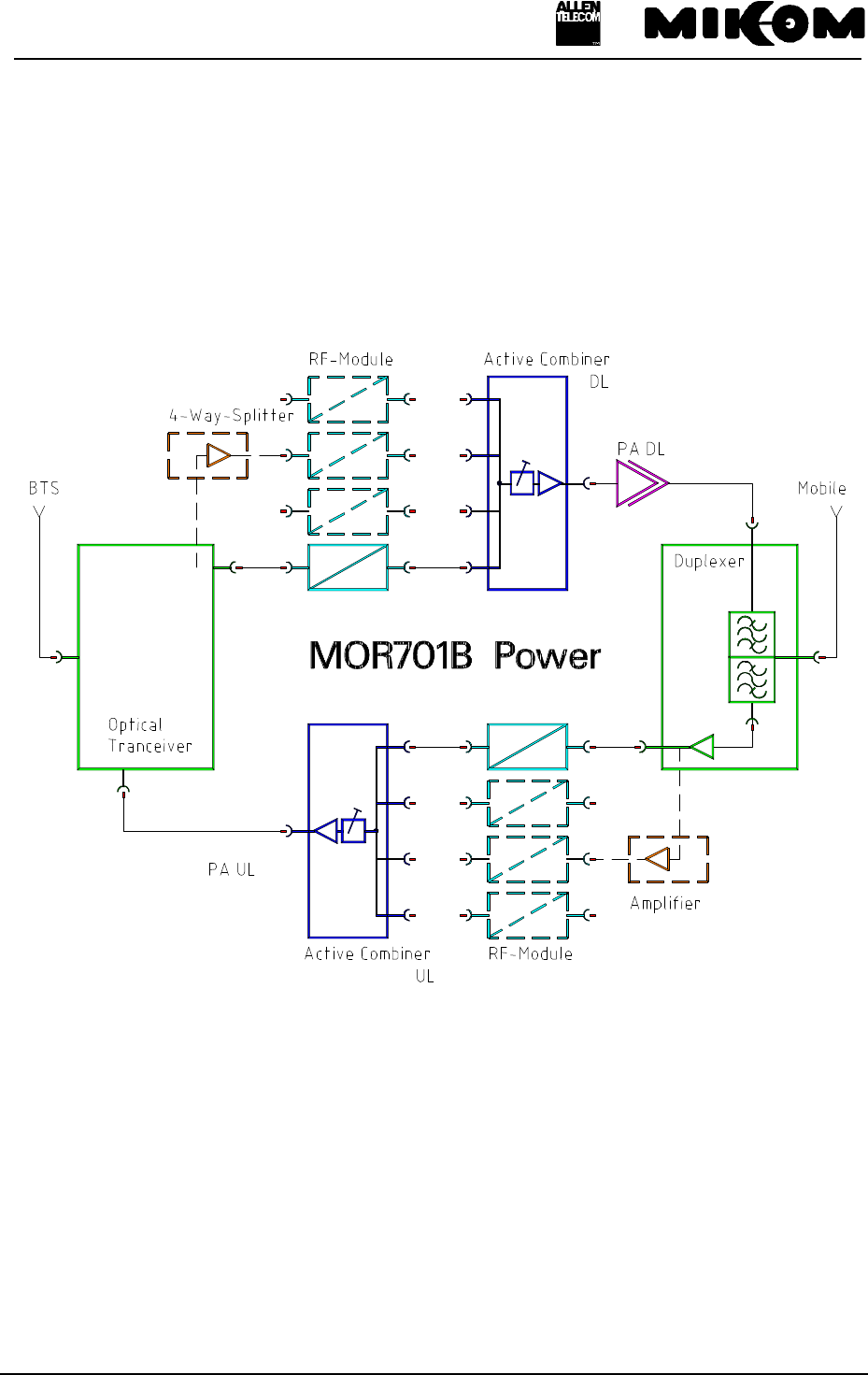
The Repeater MOR701B Power can be equipped from one to four bands or channels.
The following block diagram shall illustrate the configuration of the system.
*: one physical module contains UL and DL
**: with more than two channels, the amplifier is included
*** For correct cabling see Assembly Guide
figure 2-1 Block diagram of MOR701B Power

User’s manual for Remote Unit MOR701B Power
M0069A0A.doc Id.-No 151154 Page 15 23-June-99
2.1 General
The Repeater consists of two amplifier chains. The signals to and from the mobiles are
combined to an antenna by a frequency separation unit, denominated in the following as
Duplexer. The optical signals to and from the Master Unit are converted by the Optical
Transceiver.
In the Downlink direction the optical signals from the Master Unit are converted into RF-
signals by the Transceiver (see chapter 2.7). They pass the 4-way-Splitter (see chapter2.9),
which provides the RF-signal for the RF modules. After the RF module (see chapter 2.2) they
are combined by the Active Combiner (see chapter 2.6) and afterwards amplified by the Feed
Forward Amplifier (see chapter 2.12), which provides the required output power. Finally the
signals are fed to the antenna by the Duplexer (see chapter 2.5).
In the Uplink direction the signals from the mobiles are seperated by the Duplexer, get to a
Pre-Amplifier and afterwards to an RF module. The signals are combined by the Active
Combiner then, get converted into optical signals by the Transceiver (see chapter 2.7) and are
finally transmitted to the Master Unit.
In the final amplifier of the Downlink a power detection measures the output power and
controls the gain. In the Uplink the gain is controlled by the Active Combiner to protect the
Optical Transceiver. This power detection is called Automatic Level Control (ALC) (see
chapter 3.3).
2.2 RF modules
The task of the RF modules is to amplify the receive signals and to convert them into an
intermediate frequency. The signals, then, proceed a filter stage comprising of highly selective
filters, and run through a digital controllable attenuator. The attenuation can be set in steps of
2 dB, locally or remotely. By using the same synthesizer frequency, that was used to convert
the signals down to intermediate frequency, the intermediate frequency is mixed up to the
original frequency.
The synthesizer is controlled via an I²C-Bus. In case of a breakdown in mains, gain and
frequency data are non-volatile stored in an EEPROM on board.
See figure 2-2 Top view of an RF module for an exemplary channel or band module.
User’s manual for Remote Unit MOR701B Power
M0069A0A.doc Id.-No 151154 Page 16 23-June-99
figure 2-2 Top view of an RF module
User’s manual for Remote Unit MOR701B Power
M0069A0A.doc Id.-No 151154 Page 17 23-June-99
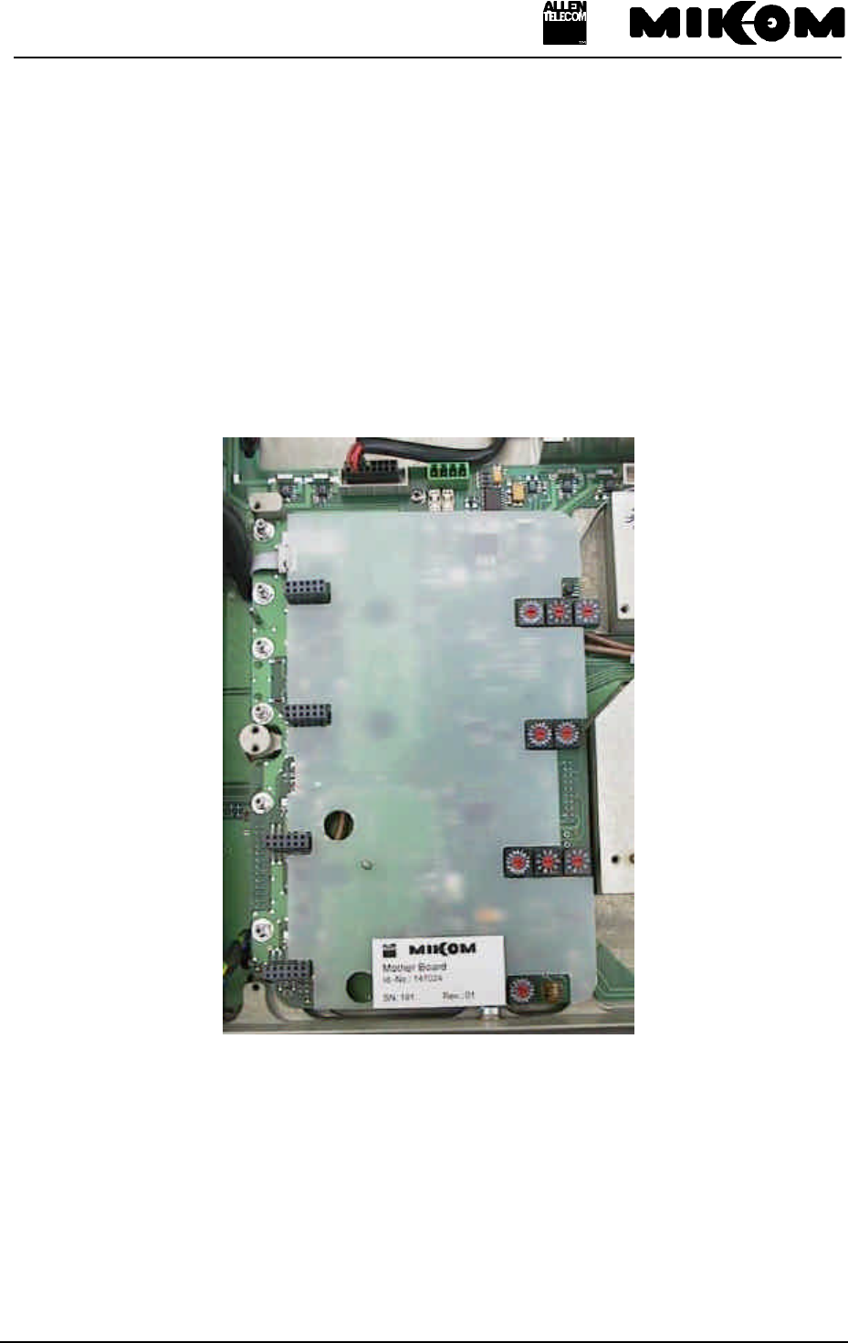
2.3 Mother board
The function of the mother board is the communication between the RF modules and the
control module via the I²C-Bus.
In the three and four channel configuration of the Repeater there is a mother board on the left-
and on the right-hand side, whereas in the one and two channel configuration there is only one
mother board implemented on the right-hand side of the Repeater.
Mother boards are located underneath the RF modules.
figure 2-3 Top view of a mother board
User’s manual for Remote Unit MOR701B Power
M0069A0A.doc Id.-No 151154 Page 18 23-June-99
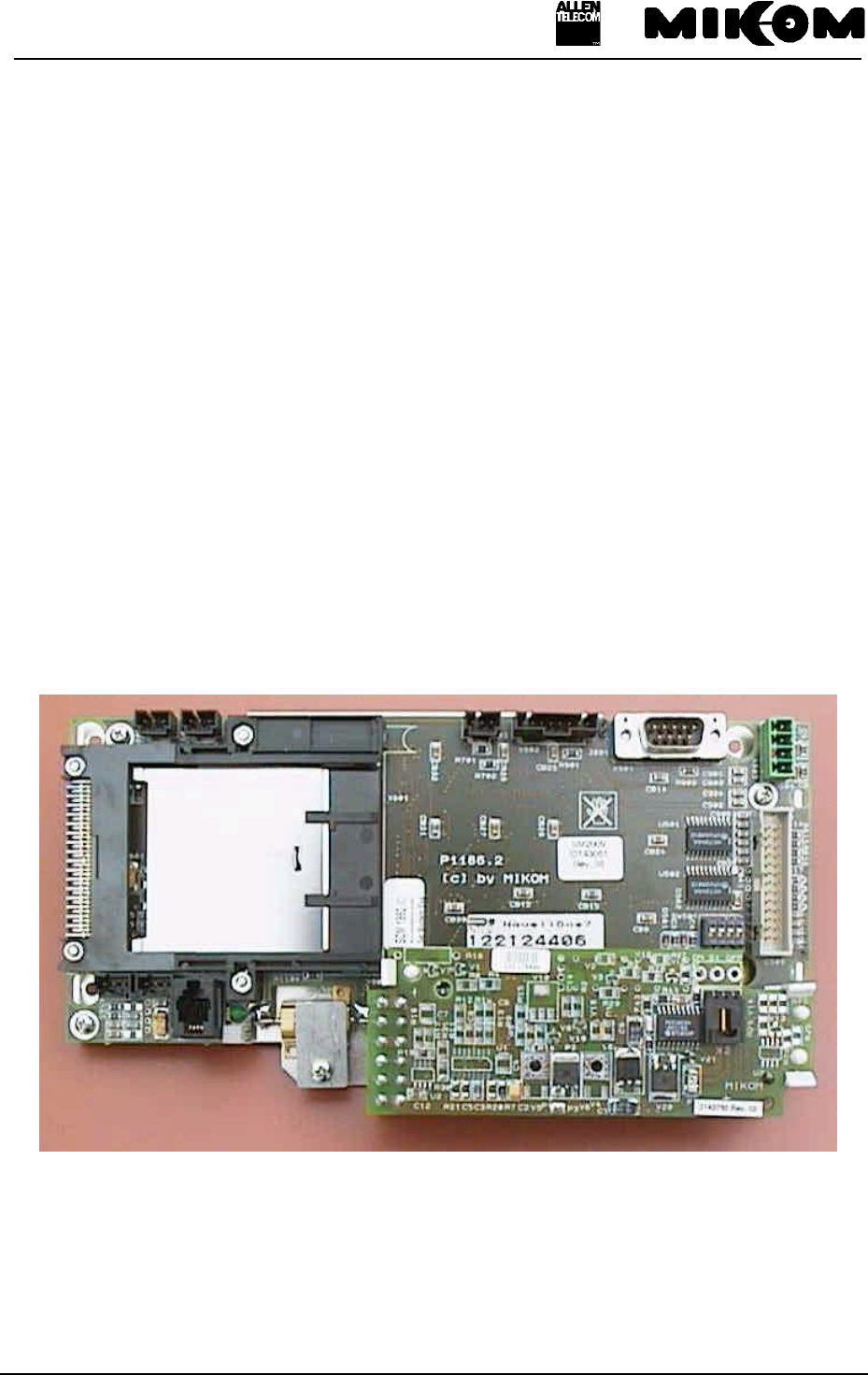
2.4 Control module SM 2009
The control module SM 2009 is a DOS compatible micro computer. The whole
communication between the operator and the Repeater can be done via the control module. By
using the RS232 interface the Repeater can be controlled locally by using a VT100 terminal,
or a PC emulating the VT100 terminal.
Frequency and gain, power down of RF stages and ALC can be controlled and status
messages can be received remotely via the Master Unit.
The data transfer between the control module SM 2009 and the mother board is realized by
the I²C-Bus system.
The I²C-Bus concept was developed by Philips for the serial connection of integrated circuits
within one device. Two wires, SDA - serial data and SCL - serial clock, carry data between
the devices connected to the bus. Each device is recognized by a unique address and can
operate either as transmitter or receiver.
All MOR701B Power configuration parameters are stored in an EEPROM on the control
module if a power supply failure occurs.
figure 2-4 Top view of the control module
User’s manual for Remote Unit MOR701B Power
M0069A0A.doc Id.-No 151154 Page 19 23-June-99
2.5 Duplexer
The task of the duplexer is to isolate uplink from downlink, i.e. isolate transmit path from
receive path. The pass bandwidth of the duplexer is the entire width of the uplink band and
the downlink band.
Two frequency - dependent versions of the MOR701B Power are available:
Id - No UL frequency DL frequency
147362 1850 - 1885 MHz 1930 - 1965 MHz
148669 1875 - 1910 MHz 1955 - 1990 MHz
figure 2-5 Top view of the duplexer
RF probe
30 dB
Duplexer
User’s manual for Remote Unit MOR701B Power
M0069A0A.doc Id.-No 151154 Page 20 23-June-99
2.6 Active Combiner
After passing through the RF modules, the signals will be combined by the Active Combiner
module in the UL and in the DL path. The Active Combiner will be followed by the feed
forward amplifier in the DL and by the Transceiver in the UL.
figure 2-6 Top view of an Active Combiner module
2.7 Transceiver MFY1319
The Transceiver MFY1319 is the interface between the optic and the electrical distribution
unit. The function of the Transceiver is to convert the optical signal into an electrical signal
and vice versa.
figure 2-7 Transceiver MFY1319
User’s manual for Remote Unit MOR701B Power
M0069A0A.doc Id.-No 151154 Page 21 23-June-99
figure 2-8 Installation position of the Transceiver
The configuration of the connecting pins is shown in the following figure.
Pin 1 GND
Pin 2 Rx Alarm normally closed
Pin 3 Tx Alarm common
Pin 4 Vcc
Pin 5 Rx Alarm common
Pin 6 Rx Alarm normally open
Pin 7 Tx Alarm normally closed
Pin 8 Tx Alarm normally open
figure 2-9 Configuration of the connecting pins
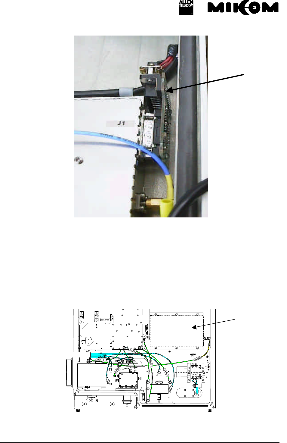
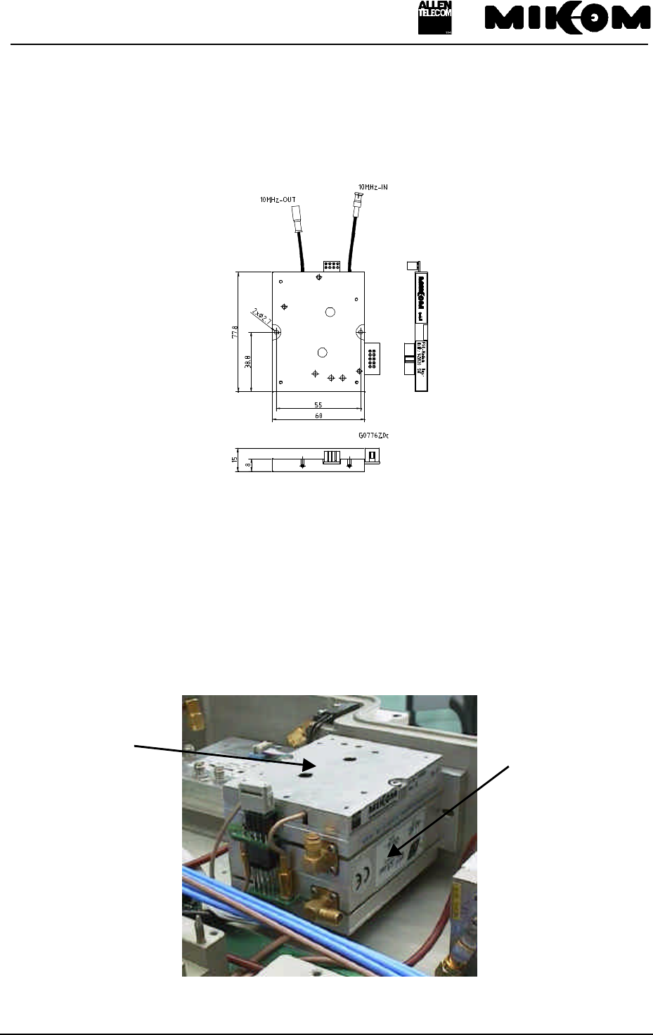
2.8 FSK modulator
To enable remote control between the Master Unit and the Remote Units a serial interface will
be implemented, in the following designated as FSK modulator. Signals from the Remote
Unit will be modulated to a 10.7 MHz carrier and are fed to the optical Transceiver to be
transmitted to the Master Unit via optical vibre and vice versa.
Transceiver
MFY1319
Optical connectors
connecting pins
User’s manual for Remote Unit MOR701B Power
M0069A0A.doc Id.-No 151154 Page 22 23-June-99
2.9 4-way-Splitter
The 4-way-Splitter provides the RF-signal to the RF modules. It splits up the signal from the
Receiver and provides four equal RF outputs with an attenuation of 10 dB for the RF
modules. It is mounted underneath the Optical Transceiver and can be seen only, if the
Transceiver is dismounted.
figure 2-10 Top view of the 4-way-Splitter (Transceiver dismounted)
2.10 Measuring aids
With the built-in RF probe test signals can be applied or detected. The duplexer is equipped
with a probe which provides a coupling factor of 30 dB. This facilitates measurements under
all operational conditions, while an antenna or a dummy load may be connected.
The position of the coupler on the duplexer is shown in figure 2-5 Top view of the duplexer.
2.11 Power supply
For the MOR701B Power three power supplies are necessary.
Power supplies are available with different mains power. See list below for available power
supplies.
User’s manual for Remote Unit MOR701B Power
M0069A0A.doc Id.-No 151154 Page 23 23-June-99
• 115 VAC ± 15% / 40 - 65 Hz
• 230 VAC ± 15% / 40 - 65 Hz
• 185 - 320 VAC / 40 - 65 Hz
• 24 VDC
• 42 to 60 VDC
• 80 to 130 VDC
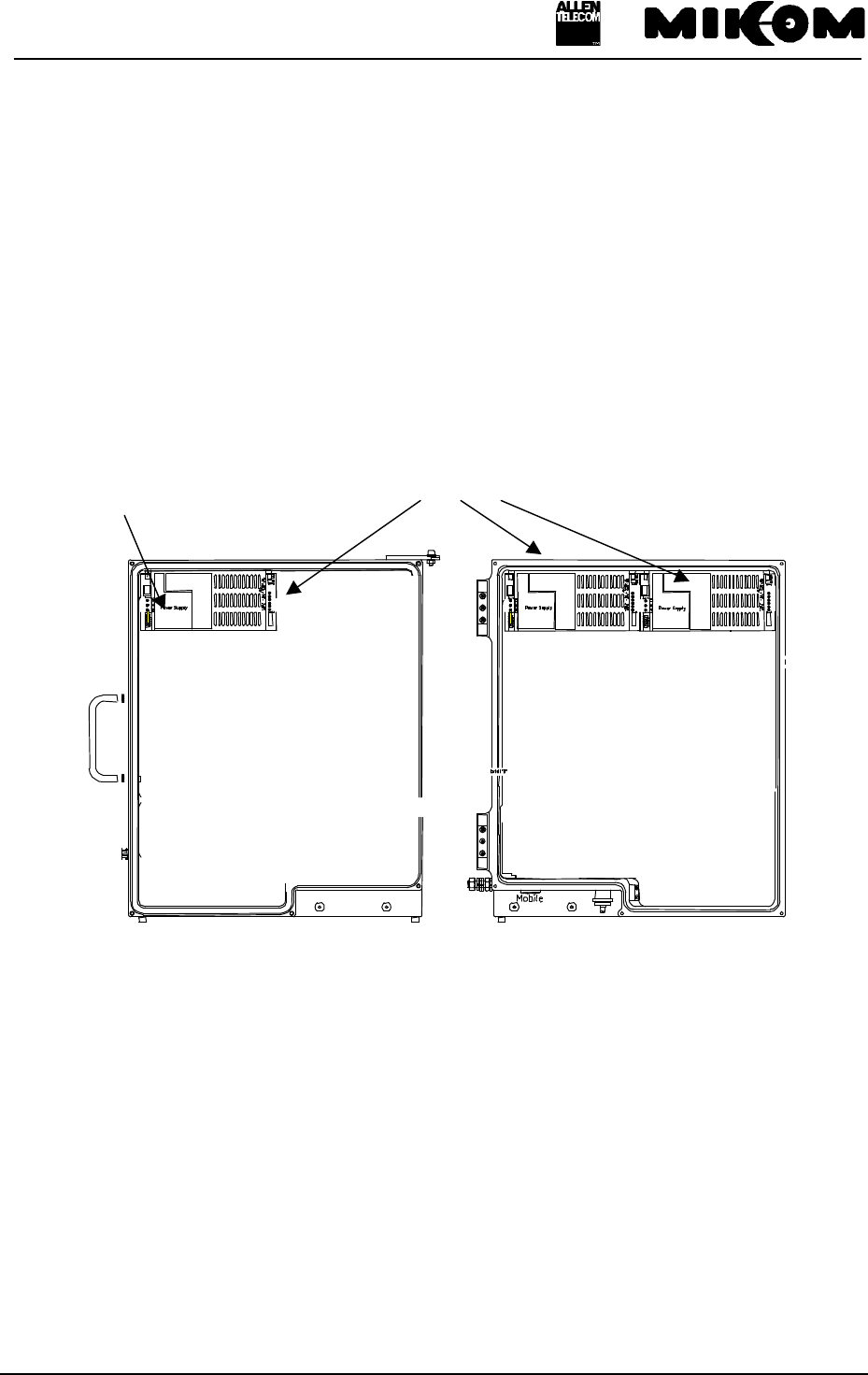
The following figure shows the mounting position of the power supplies in the MOR701B
Power cabinet.
* service connector is not included in each power supply
figure 2-11 Mounting position of power supplies
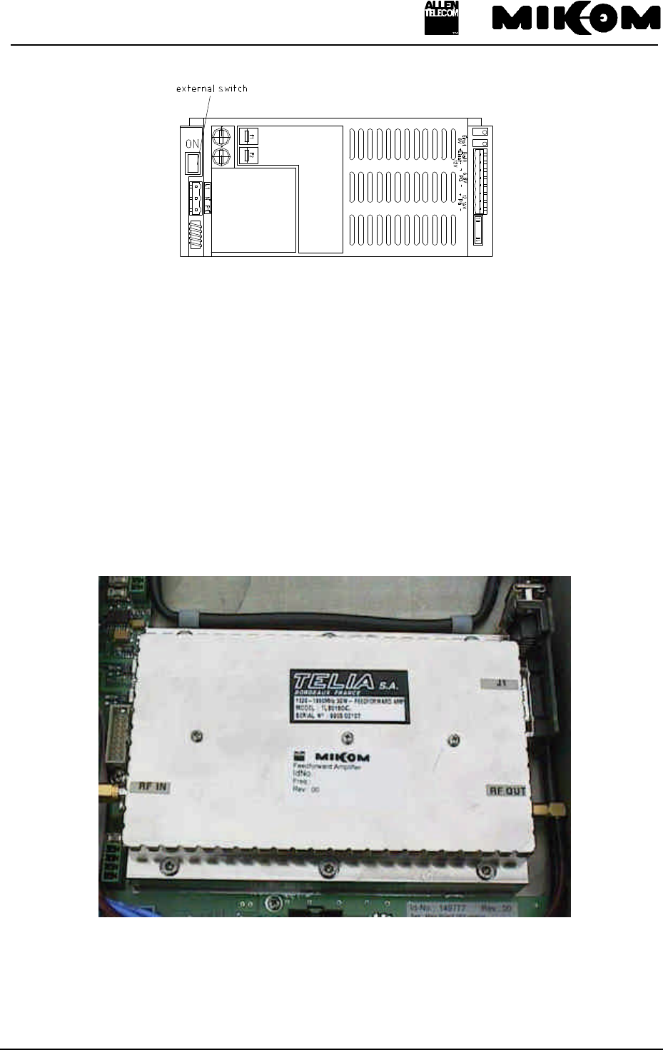
The power supplies are equipped with a power socket, protected with two fuses. Each power
supply can be switched on or off by means of an external switch. The modules of the Repeater
are voltage free if all power supplies are switched off. The power socket, however, is still
provided with mains power.
See figure 2-12 ON / OFF position of external switch.
Power supplies
power socket
(service connector*)
G0850M0
User’s manual for Remote Unit MOR701B Power
M0069A0A.doc Id.-No 151154 Page 24 23-June-99
figure 2-12 ON / OFF position of external switch
F Note: To switch the whole Repeater voltage free, you have to remove the
fuses F1 and F2 on the screw terminal.
The power supply is factory-set.
2.12 Feed forward amplifier
The feed forward amplifier is the final stage which enables high output power as well as a
high ICP3. One amplifier is installed for the DL Out path.
figure 2-13 Top view of the feed forward amplifier
User’s manual for Remote Unit MOR701B Power
M0069A0A.doc Id.-No 151154 Page 25 23-June-99
3 Functions and features
3.1 Band and channel selectivity
The selectivity is achieved by highly selective filters in the IF part of the band / channel
modules.
3.2 Gain setting
The gain can be changed by introducing attenuation into the amplifier chain. By using a rotary
switch the attenuation can be adjusted locally in the range from 0 dB to 30 dB maximum in
steps of 2 dB. The attenuation can be set for the UL and DL path separately.
The rotary switches are mounted on the mother board. These switches are accessible through
the long hole between the two RF modules (see figure 3-1 Position of rotary switches). They
can be adjusted easily by means of a small screwdriver.
figure 3-1 Position of rotary switches
For remote control an RS232 interface can be used to set the gain.
The functions of the control module may be used locally by means of a VT100 terminal or a
personal computer emulating the VT100 terminal. See also chapter 7.2, which deals with
settings of operational parameters.
long hole
User’s manual for Remote Unit MOR701B Power
M0069A0A.doc Id.-No 151154 Page 26 23-June-99
3.3 ALC
In order to protect the final amplifier and the optical devices from overload and to prevent the
system to generate spurious emission, the amplifier for the DL Out and the Active Combiner
for the UL Out have an Automatic Level Control, designed to limit the output power to a
defined level. A part of the output power is rectified, amplified and used to control an
attenuator network. In order to avoid oscillation, the control amplifier has an integrating
characteristic, so that a step function response obtains a delayed rise and decay.
FNote: The ALC protects the final amplifier and the optical devices. To keep
spurious emissions below certain limits, the input power into the Repeater
and the attenuation settings of the Repeater have to be considered
properly.
3.4 BITE and alarms
The Built-In TEst concept comprises the monitoring of the power supplies, the operational
currents in the RF modules, the mother board and the remote control interface. Furthermore,
the synthesizer lock and the temperature of the Repeater are monitored.
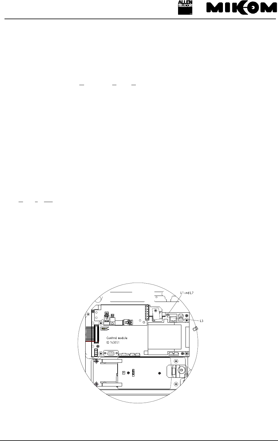
There are three multicoloured LEDs mounted on the control module. The LED L3 indicates
the presence of electrical power of +12VDC in the Repeater. Every alarm is indicated by the
failure LEDs, L1 and L2.
Position of the LEDs on the control module is shown in the following figure.
figure 3-2 Position of failure LEDs
User’s manual for Remote Unit MOR701B Power
M0069A0A.doc Id.-No 151154 Page 27 23-June-99
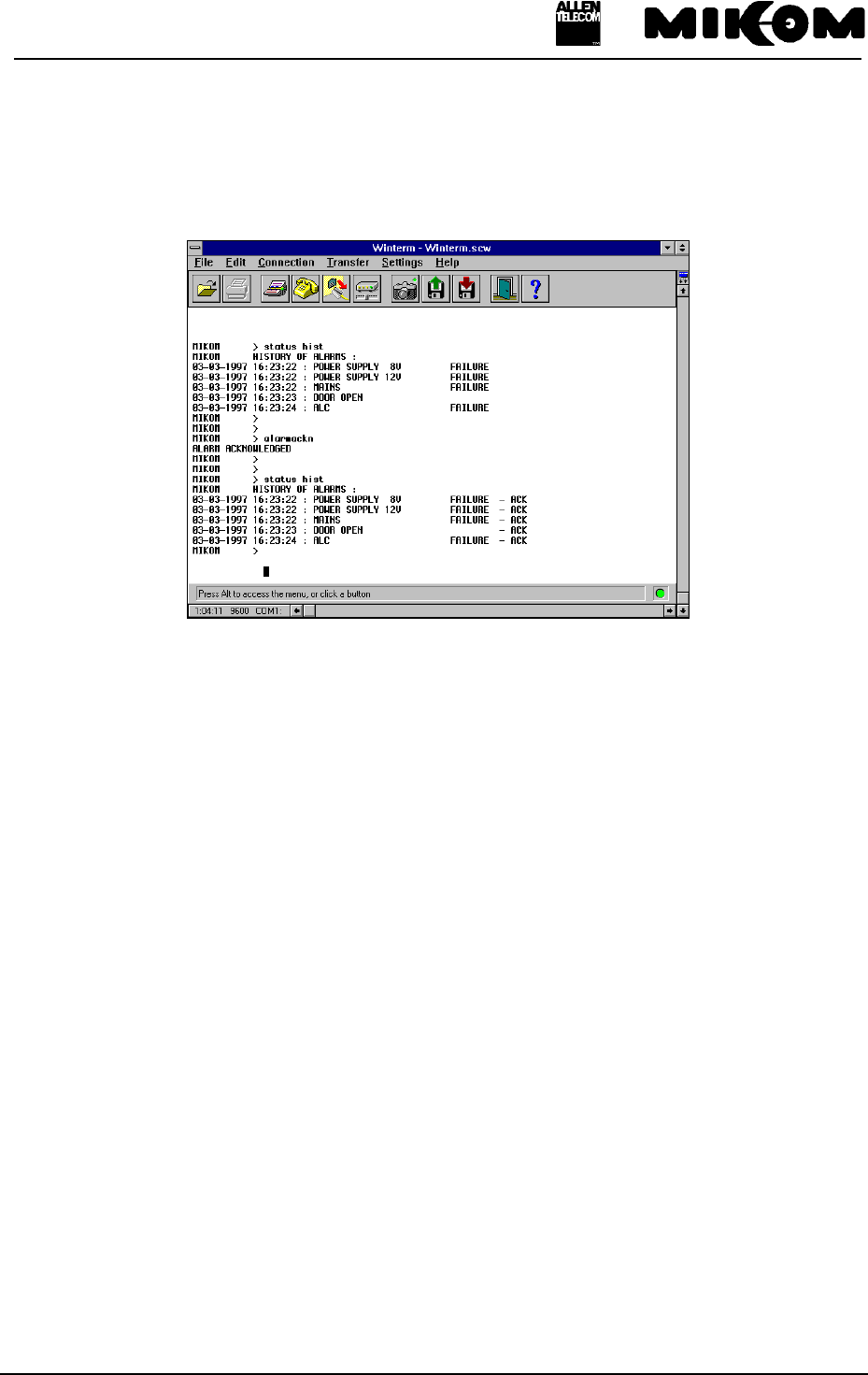
All alarms can be checked by typing the ‘STATUS HIST’ command. It is possible to cancel
minor alarms with no influence on the system by typing the ‘ALARMACKN’ command, e.g.
ALC active, VSWR or door open. The following print screen illustrates a possible ‘STATUS
HIST’ report
figure 3-3 Status hist report
In case a hardware failure is detected the concerning hardware module has to be replaced. An
alarm can be acknowledged manually by software command. If all alarms have been
acknowledged the summary error LEDs are set back to green indication.
In case of mains power failure all data of the STATUS HIST list are lost.
The alarm can also be sent to the OMC.
The following list comprises all available alarms in the Repeater. These alarms may occur in
the STATUS HIST list.

User’s manual for Remote Unit MOR701B Power
M0069A0A.doc Id.-No 151154 Page 28 23-June-99
NO. ALARM NAME ALARM ACTIVE STATUS
1AMPLIFIER BIAS FAILURE
2POWER SUPPLY 8 V FAILURE
3POWER SUPPLY 12 V FAILURE
4MAINS FAILURE
5SYNTH FAILURE
6DOOR OPEN
(7) VSWR ALARM
8ALC FAILURE
9LITHIUM BATTERY VOLTAGE LOW
10 OVERTEMP
11 INVALID LOGIN ATTEMPT
12 I2C BUS FAILURE
(13*) EXT. ALARM 1 FAILURE
(14*) EXT. ALARM 2 FAILURE
(15*) EXT. ALARM 3 FAILURE
(16*) EXT. ALARM 4 FAILURE
(17**) EXT. BATTERY OVERTEMP.
* Alarm default settings changeable by software instruction SET ALIAS.
** This alarm may be activated together with the external alarms, for instance UPS
temperature
(...) Optional alarms
table 3-4 List of all available alarms
3.4.1 Handling of alarms
As soon as the software recognizes a valid alarm, a message is transmitted to theMaster Unit.
If the reason for the alarm has been cleared or if the alarm should continue, a new alarm
message will not be repeated. If there was an interruption of at least one second after
acknowledgement, a new alarm message will be generated.
User’s manual for Remote Unit MOR701B Power
M0069A0A.doc Id.-No 151154 Page 29 23-June-99
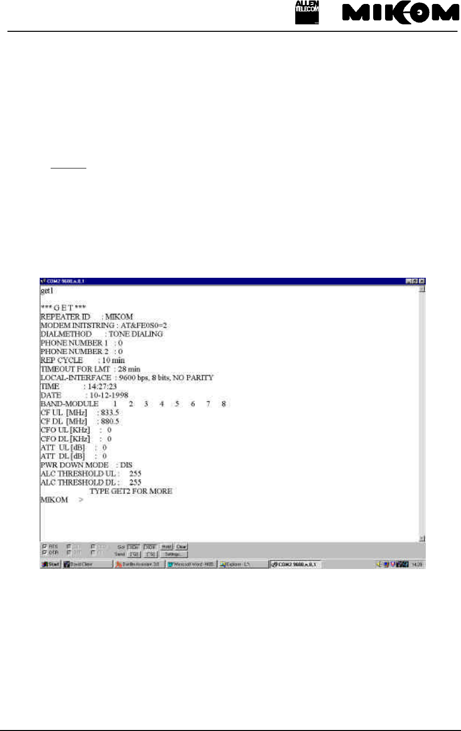
3.4.2 Status report
Two instructions enable the operator to gain knowledge of the system status. Typing the GET
command will be responded by a listing of all settings of the Repeater. STATUS will be
responded by a listing of all individual status information.
An example is listed below for a GET1* (REP1009V1.xx) and STATUS report. The listing
contains random data to demonstrate in which way these messages appear.
*: Due to the fact that the report is very long, the GET report can be split in two parts. You have to type GET1 to
see the first and GET2 to see the second part.
The complete listing of the dialogue language with the processor of the control module
including the instructions to and the messages from the system is available as a separate
manual.
figure 3-5 Example of a GET1 report
User’s manual for Remote Unit MOR701B Power
M0069A0A.doc Id.-No 151154 Page 30 23-June-99
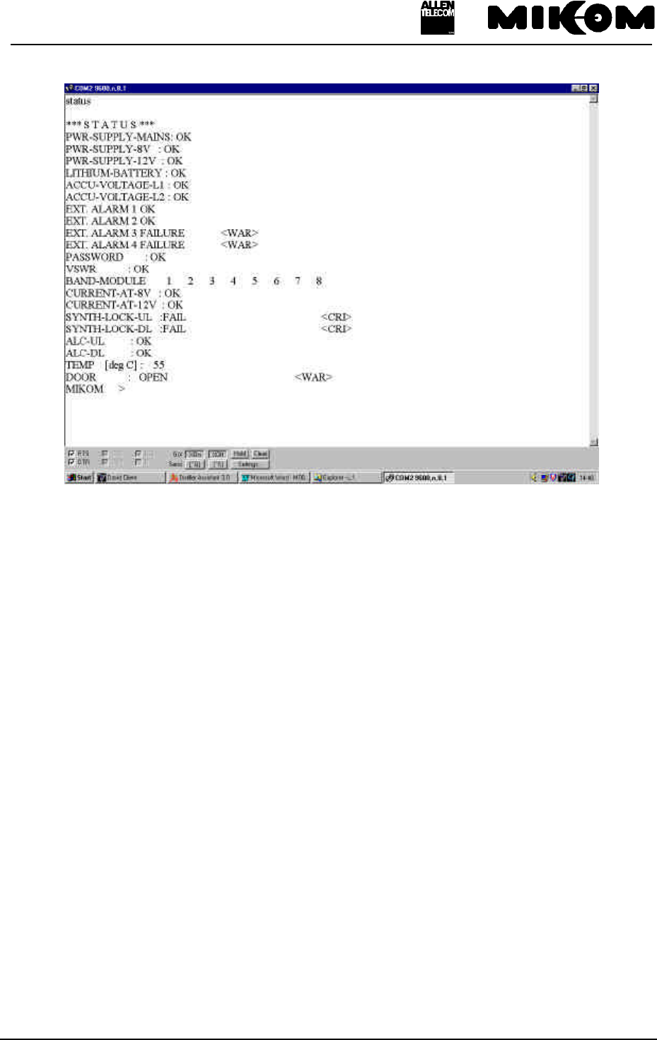
figure 3-6 Example of a STATUS report
3.4.3 Severity levels
This parameter defines five severity levels for an alarm and can be set in the alarm mask
(detailed description in the software manual). The severity levels indicate how the capability
of the managed object has been affected.
The levels are described below and are ordered from most severe to least severe:
- Critical: The critical severity level indicates that a service affecting condition has
occurred and an immediate corrective action is required to restore the
capability of the managed object.
- Major: The major severity level indicates that a service affecting condition has
developed and an urgent corrective action is required. Such a severity can be
reported, for example, when there is a severe degradation in the capability of
the managed object and its full capability must be restored.
- Minor: The minor severity level indicates the existence of a non-service affecting fault
condition and that corrective actions should be taken in order to prevent a more
serious failure. Such a severity can be reported, for example, when the detected
alarm condition is not currently degrading the capability of the managed object.

User’s manual for Remote Unit MOR701B Power
M0069A0A.doc Id.-No 151154 Page 31 23-June-99
- Warning: The warning severity level indicates the detection of a potential or impending
service affecting failure before any significant effect has been caused. Action
should be taken to further diagnose and correction of the problem shall prevent
a more serious service affecting failure.
- Disable: The disable severity level indicates that the detected failure has no influence on
the system and shall not be sent to the terminal.
User’s manual for Remote Unit MOR701B Power
M0069A0A.doc Id.-No 151154 Page 32 23-June-99
4 Optional equipment
The following modules can be integrated as an option.
4.1 VSWR module
VSWR signal is continually measured by a special VSWR module. An alarm can be given for
VSWR < 10 dB.
4.2 External alarms
With the following option it is possible to monitor 4 external alarms via the Repeater
software. Hence the status of the connected device, e.g. UPS, can be monitored.
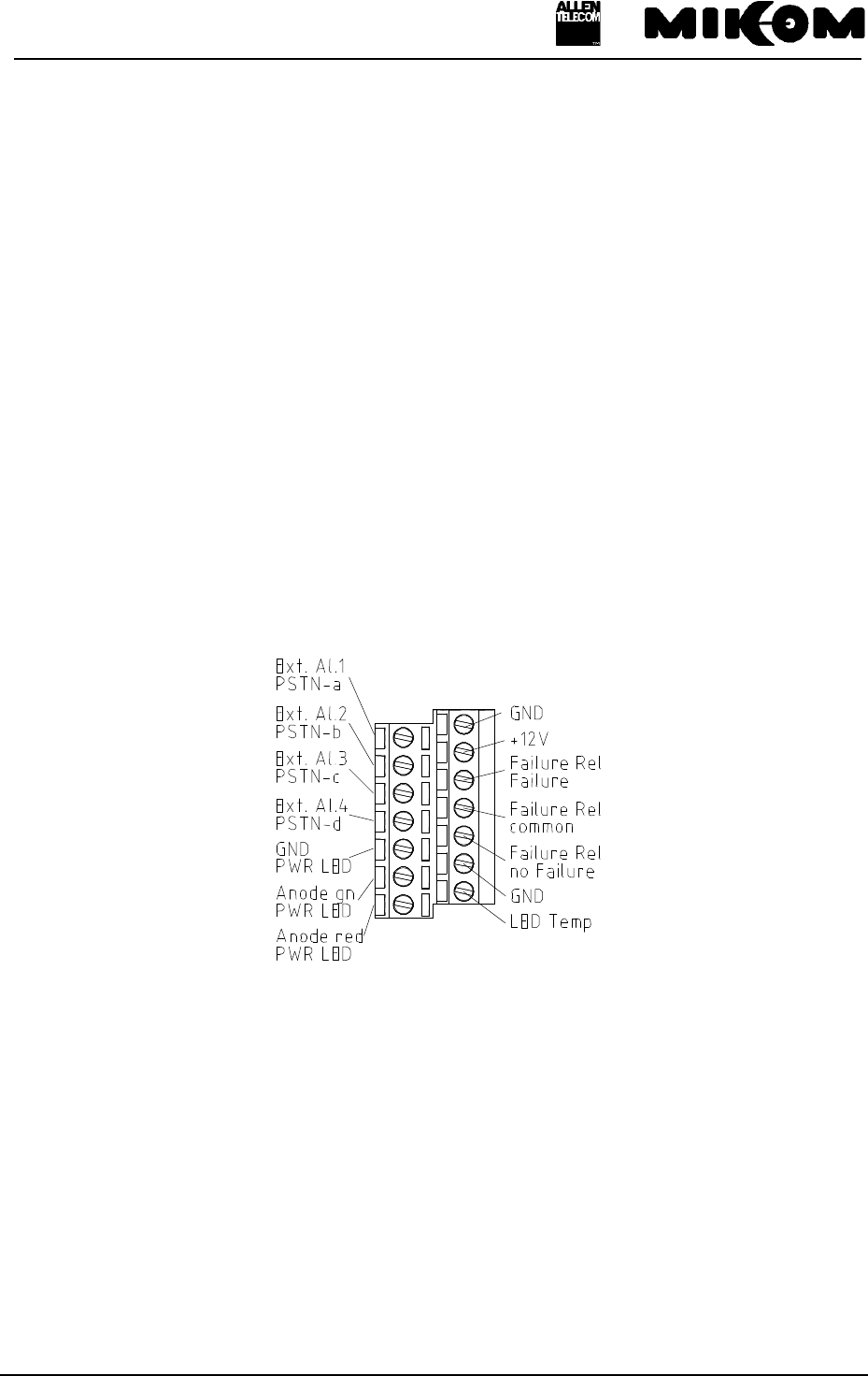
The contacts of the alarms can be accessed at clamps on the main board (right-hand side of
the Repeater).
figure 4-1 Clamps for external alarms

User’s manual for Remote Unit MOR701B Power
M0069A0A.doc Id.-No 151154 Page 33 23-June-99
The electrical connection has to be as follows.
External alarm 1 (low active)
External alarm 2 (low acitve)
External alarm 3 (high active)
External alarm 4 (high active)
Ground
Configuration: 5 V / 0.5 mA max. for open collector applications.
All external alarms are normally high without connection. Due to the fact that the external
alarms 3 and 4 are high active, they have to be connected to ground to prevent an alarm
message.
The factory-set response after typing the software command STATUS EXTALARM is for
instance „EXT. ALARM 1 OK“, if the alarm is not active and „EXT. ALARM 1 FAILURE“,
if the alarm is active.
The name for each external alarm and the name for the alarm message can be defined by the
customer with the corresponding software command.
The following example describes the response for the external alarms to control a UPS.
Example: External alarms if the UPS is active
EXTERNAL ALARM STATUS
UPS alarm active
Battery low !
UPS door open
Battery door open
or External alarms if the UPS is not active
EXTERNAL ALARM STATUS
UPS not active
Battery OK
UPS door closed
Battery door closed
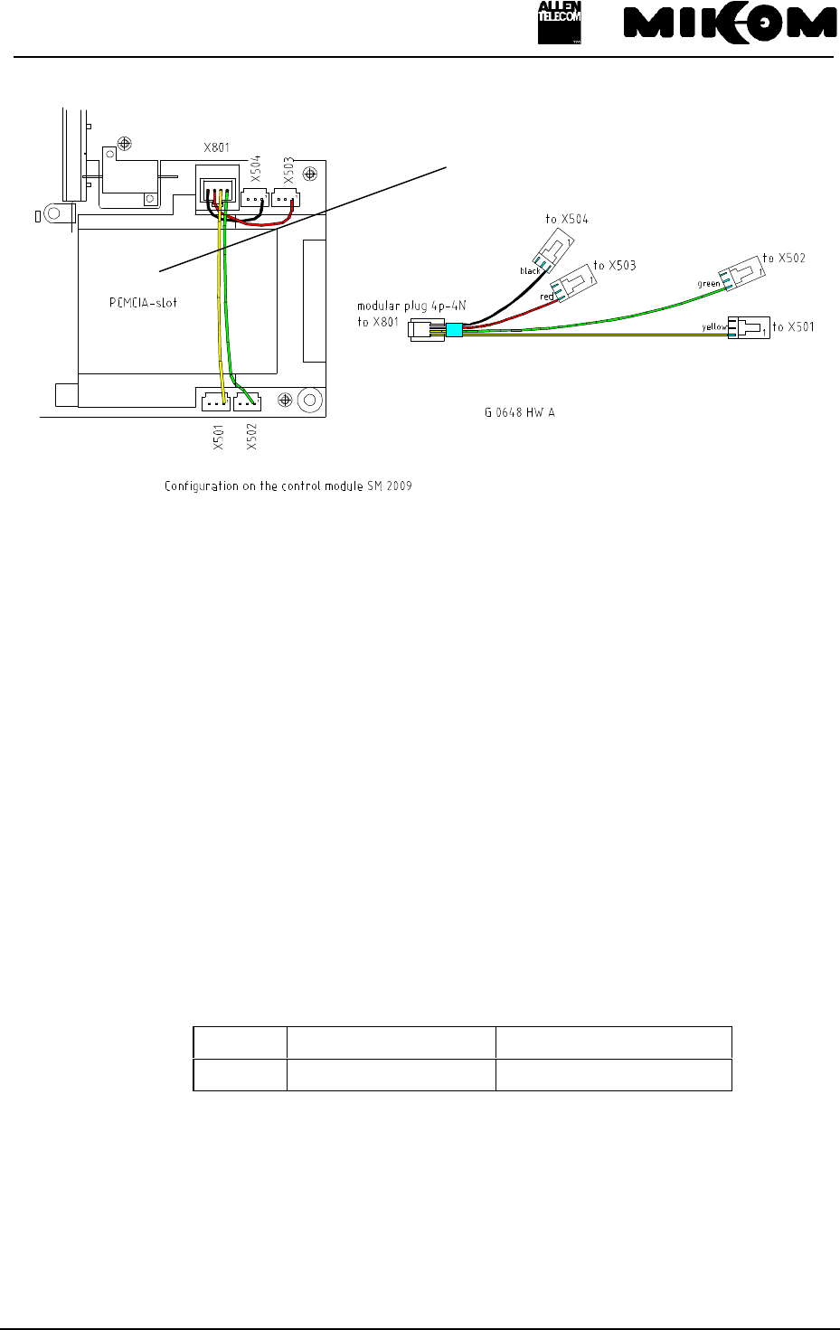
For the DC wiring an additional cable bridge has to be installed on the control module (see
figure 4-2 Cable configuration and installation position).
User’s manual for Remote Unit MOR701B Power
M0069A0A.doc Id.-No 151154 Page 34 23-June-99
figure 4-2 Cable configuration and installation position
4.3 Battery backup module
If backup is required only for the control module, low capacity batteries are available to
operate the controller for at least ten minutes under normal environmental conditions.
Battery backup is provided for the control module to transmit alarm information in case of
power failure. The battery type is a NiCd 8.4V/300 mAh.
F Note: This battery backup module is provided for the control module only.
The batteries are protected from deep discharge by use of a low voltage disconnect circuit. A
local switch is provided to disconnect the battery backup system during maintenance to ensure
that all circuits are voltage-free.
The switch is located on the battery backup module.
Switch ON ( default ) OFF
Battery backup active Battery backup not active
The module is directly plugged into the control module. During the charging process a green
LED V7 on the module indicates, that the battery is charged at the moment. After finishing
the process the LED V7 will be switched off.
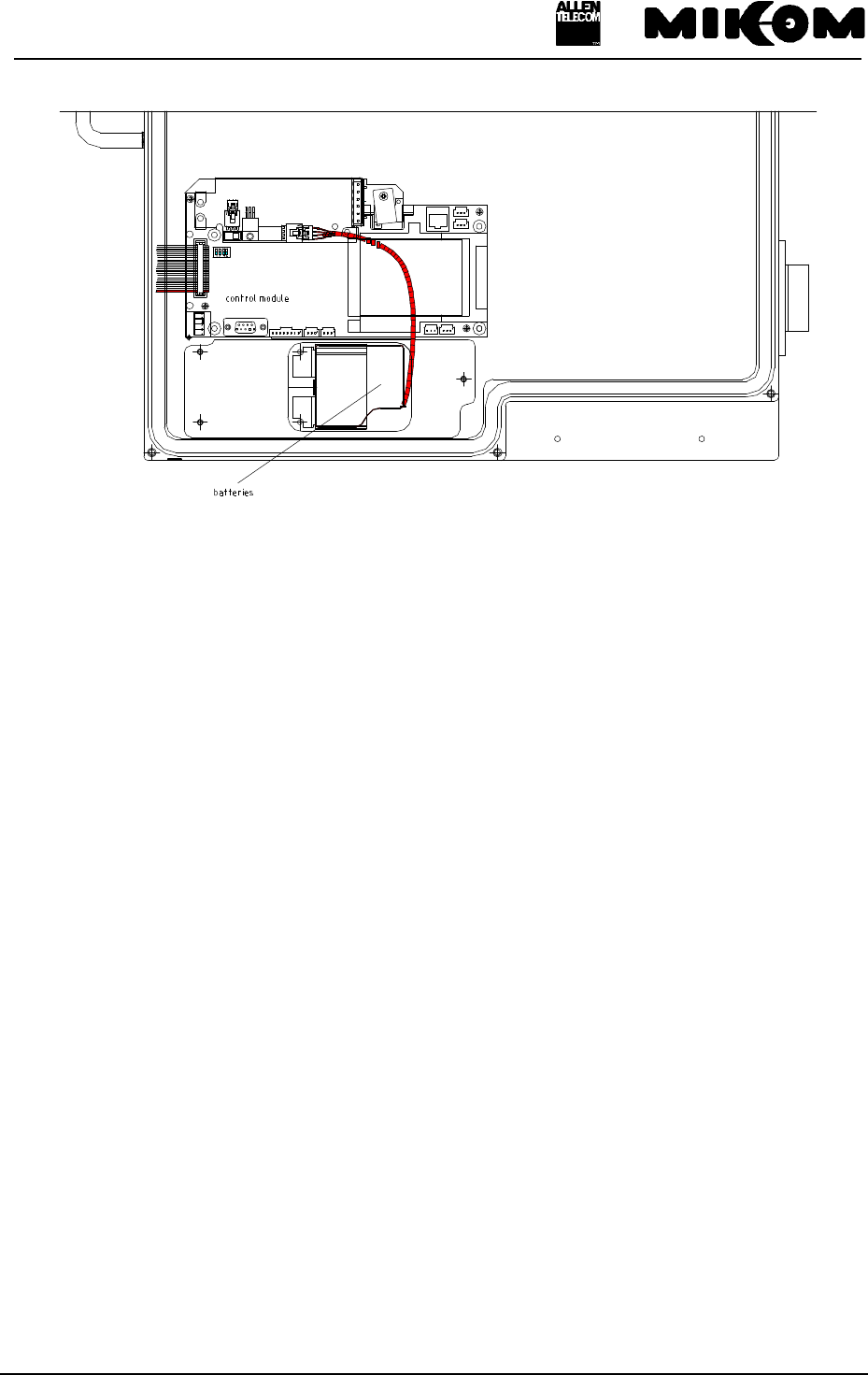
The batteries are mounted underneath the modem mounting plate (see following figure).
Control module
User’s manual for Remote Unit MOR701B Power
M0069A0A.doc Id.-No 151154 Page 35 23-June-99
figure 4-3 Mounting position of batteries

User’s manual for Remote Unit MOR701B Power
M0069A0A.doc Id.-No 151154 Page 36 23-June-99
5 Specification
5.1 Electrical specification
Frequency range UL: 1850 - 1885 MHz; DL: 1930 - 1965 MHz
UL: 1875 - 1910 MHz; DL: 1955 - 1990 MHz
Useable bandwidth 35 MHz in the upper or lower PCS1900 band
Gain 65 dB
Gain variation over
frequency and temperature* ±2.5 dB (±3.5 dB at extreme temperatures)
Gain adjust range 30 dB in 2 dB steps
Gain adjust range tolerance ±0.5 dB
Return loss 15 dB @ 25°C ambient temperature
Spurious/intermodulation -13 dBm max
Spectral re-growth (CDMA only) -45 dBc (J-STD-008)
Power supply 115 VAC ± 15% / 40 - 65 Hz
Option: 230 VAC ± 15% / 40 - 65 Hz
Option: 185 - 320 VAC / 40 - 65 Hz
Option: 24 VDC
Option: 42 to 60 VDC
RF connector 7/16 female
Option: N female
Environmental and safety See separate leaflet
*: Normal temperature range +5° to +40°C; Extreme temperature range -33° to +50°C

User’s manual for Remote Unit MOR701B Power
M0069A0A.doc Id.-No 151154 Page 37 23-June-99
BAND AND CHANNEL SPECIFICATIONS
Option I
(fixed bw) Option II
(fixed bw) Option III
(variable bw) Channel
CDMA TDMA
3 dB bandwidth 5 MHz 15 MHz 0.1 to 15
MHz 1.23 MHz 30 kHz
Slope 3 dB to 30 dB 1 MHz 2 MHz 2 MHz - -
30 dB bandwith - - - fc ± 900kHz fc ±60 kHz
50 dB bandwith - - - fc ± 1.5 MHz fc ± 120 kHz
Delay 6 µs 3 µs 6 µs < 6 µs 20 µs
Delay variation
(typical) ±150 ns ±150 ns ±150 ns ±500 ns ±500 ns
Far off selectivity 40 dB 40 dB 40 dB 60 dB 55 dB
NF at Gmax 6 dB 6 dB 8 dB 6 dB 6 dB
NF at Gmax-30 dB 12 dB 12 dB 13 dB 12 dB 12 dB
OICP-3 at Gmax 59.0 dBm 59.0 dBm 59.0 dBm 59.0 dBm 59.0 dBm
OICP-3 at Gmax -
10 dB 58.6
dBm
58.5
dBm
58.5
dBm
58.5
dBm
59.0
dBm
OICP-3 at Gmax -
20 dB 58.0
dBm
58.0
dBm
57.5
dBm
58.0
dBm
58.5
dBm
OICP-3 at Gmax -
30 dB 56.0
dBm
56.0
dBm
53.0
dBm
55.0
dBm
57.0
dBm
Output noise
in band at Gmax -78 dBm/Hz -78 dBm/Hz -76 dBm/Hz - -
Output noise out of
band at Gmax -98 dBm/Hz -98 dBm/Hz -96 dBm/Hz - -
Power consumtion
standby/max power
1 module (typ.cons)
4 modules (typ.cons)
130/220W
160/250W
130/220W
160/250W
145/220W
180/270W
130/210W
160/240W
130/210W
160/240W
All data is subject to change without notice !

User’s manual for Remote Unit MOR701B Power
M0069A0A.doc Id.-No 151154 Page 38 23-June-99
5.2 Optical specification
Max. allowed optical loss Master / Remote 10 dB*
*optical loss up to 13 dB with slightly
degraded specifications
Required optical return loss
reflection + backscatter 45 dB
5.3 Mechanical specification
Standard cabinet
Max. Height x Width x Depth: 21.1 x 18.2 x 7.9 inches
535 x 462.5 x 200 mm
Volume: approximately 45 litres
Weight: approximately 103 lbs (47 kg per unit in standard
configuration)
The illustration of chapter 12.1 provides the dimensions and the view of the layout.
5.4 Environmental and safety
For detailed information refer to the environmental and safety specification leaflet for
MIKOM indoor / outdoor cell enhancers, related to ETS 300019 (European Tele-
communication Standard).
Operating temperature (normal temperature range): + 5° C ... + 40° C
(extreme temperature range): - 33° C ... + 50° C
Humidity: + 30° C/ 93 %
User’s manual for Remote Unit MOR701B Power
M0069A0A.doc Id.-No 151154 Page 39 23-June-99
5.5 External electrical interfaces
5.5.1 Electrical power
The Repeater MOR701B Power can be supplied with the following power supplies (mains):
• 115 Vac ± 15% 40 - 65 Hz
• 230 V ac ± 15% 40 - 65 Hz
• 185 - 320 Vac 40 - 65 Hz
• 24 Vdc
• ±42 to ±60 Vdc
• ±80 to ±130 Vdc
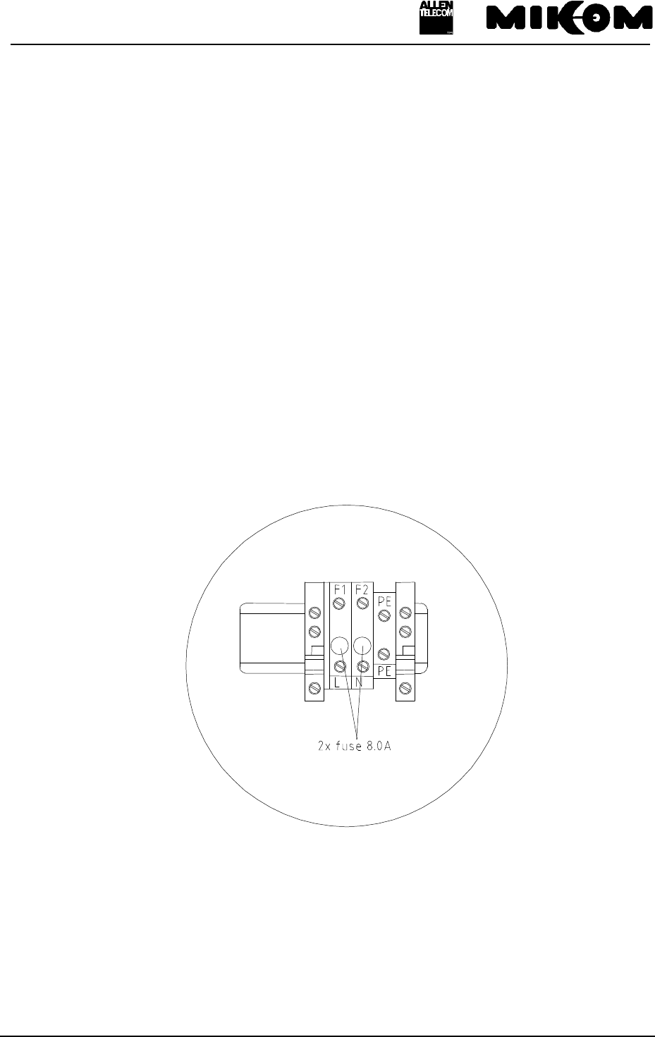
A firmly installed mains cable is used, which is fed into the housing through a watertight
cable gland. Due to safety reasons the power supply lead has to be protected by two 8 A fuses.
Inside the Repeater, mains are connected to a screw terminal.
See figure 5-1 Screw terminal for mains cable for the position of the two 8 A fuses.
figure 5-1 Screw terminal for mains cable
User’s manual for Remote Unit MOR701B Power
M0069A0A.doc Id.-No 151154 Page 40 23-June-99
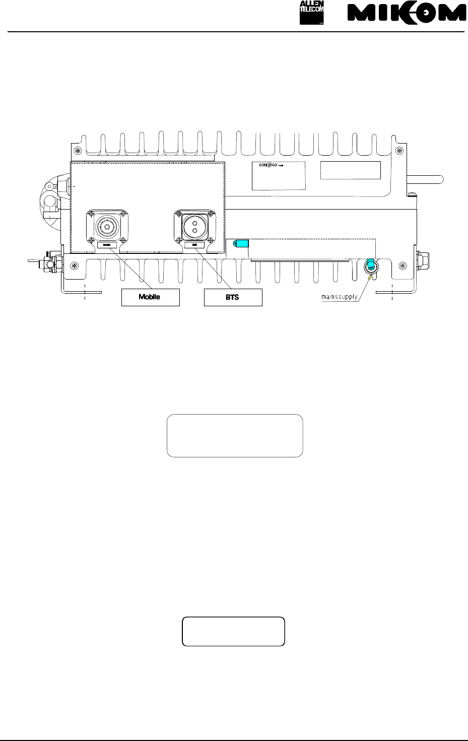
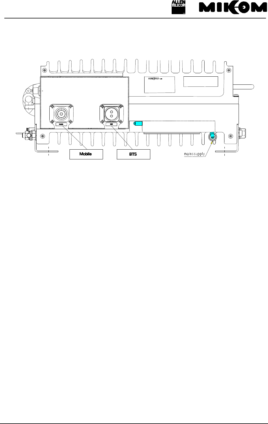
5.5.2 RF connection
There is a 7/16 female antenna connector at the outside of the housing accessible on the
connector panel.
figure 5-2 Connector panel layout
The 7/16 TX-downlink connector should be connected to the antenna system for the
communication with the mobile units.
Mobile
As an option a 7/16 - N adapter is available.
5.5.3 Optical connector
The Remote Unit is connected to the Master Unit via optical fibres. Therefore two optical
connectors (DIN, SC/APC or FC/APC) are available at the front side of the Repeater. They
are labelled with RX and TX.
BTS
G0850Z0
User’s manual for Remote Unit MOR701B Power
M0069A0A.doc Id.-No 151154 Page 41 23-June-99
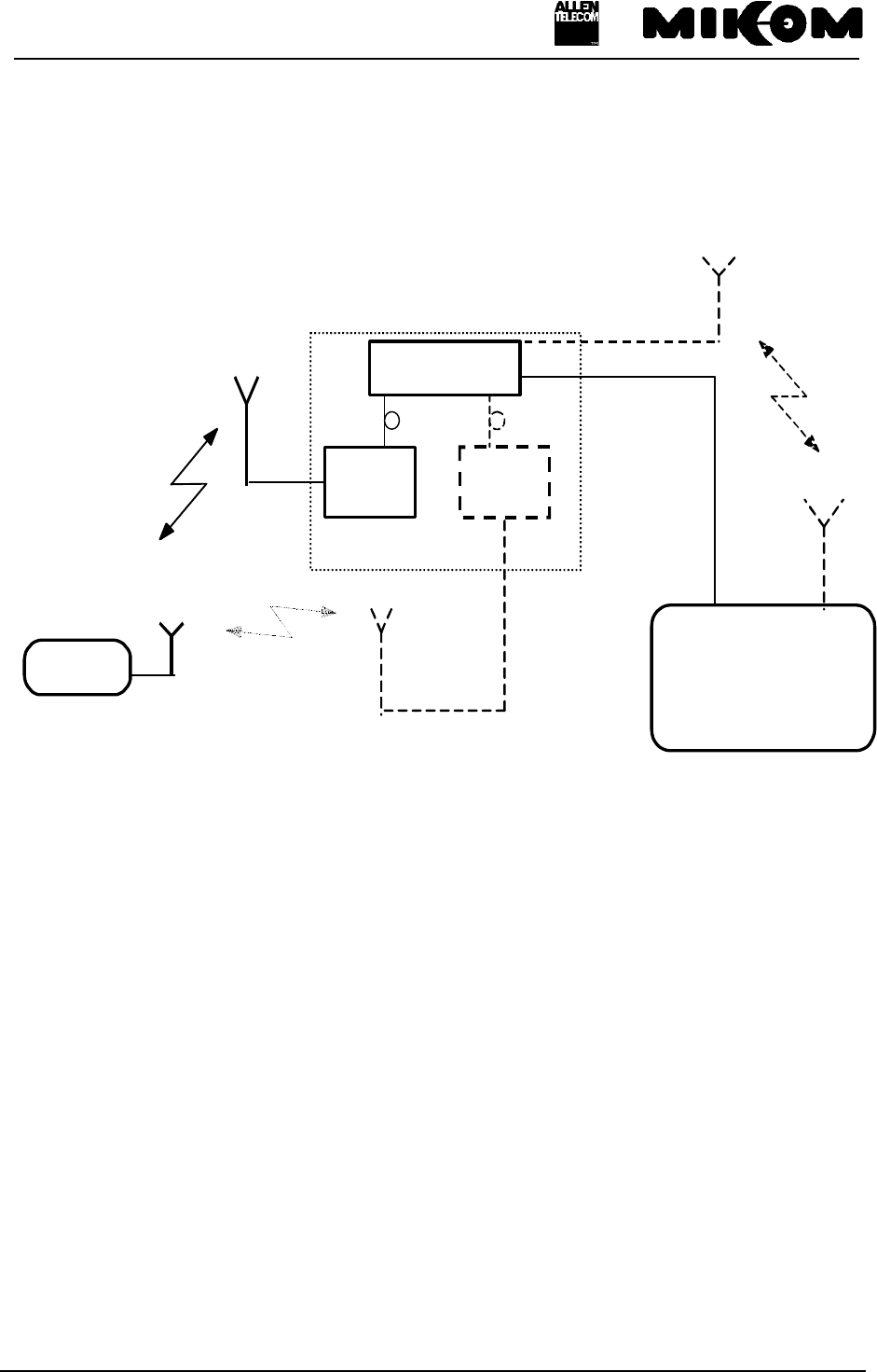
6 Installation
BTS
RX Uplink
TX Downlink
Mobiles
TX Uplink
RX Downlink
to/from
mobile stations
to/from
BTSRepeater System
*
Master Unit
Remote
Unit 1 Remote
Unit xx.
...
**
*: This is possible alternativly
**: The number of Remote Units depends on the configuration of the Master Unit
figure 6-1 System description
User’s manual for Remote Unit MOR701B Power
M0069A0A.doc Id.-No 151154 Page 42 23-June-99
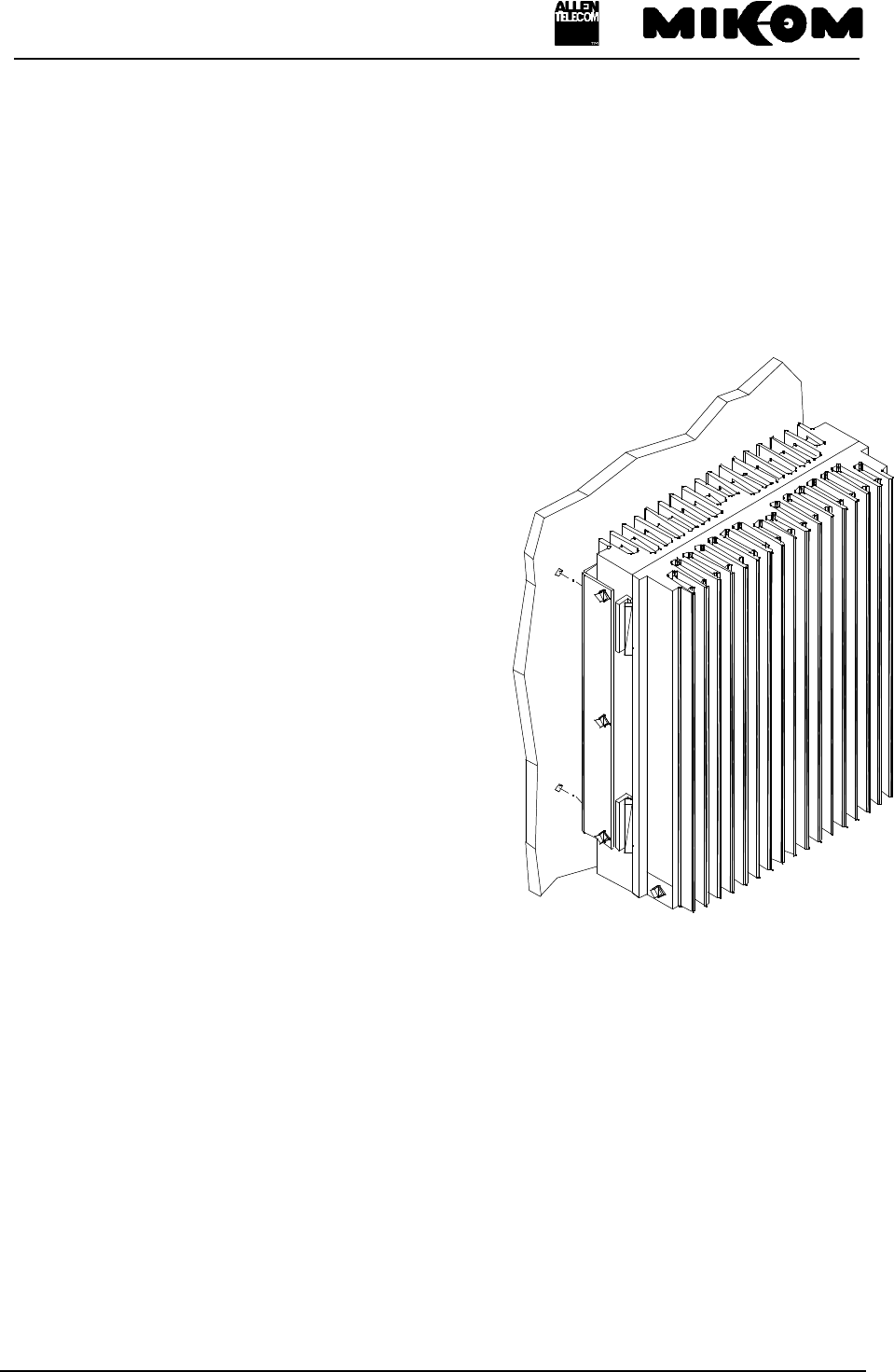
6.1 Mechanical installation
F Note: Due to power dissipation the Repeater may heat up the air volume inside
the cabinet and reach a very high temperature. Therefore it is necessary to mount the
Repeater in the vertical plane to a wall or a mast without additional enclosure to provide
sufficient ventilation. Between the housing and the wall a minimum distance must be
kept in order to provide air circulation.
F Note: The weight of the MOR701B Power is approximately 47 kg in standard
configuration.
The Repeater must be mounted in the vertical
plane to a wall or a mast, which means the
connectors have to be located at the bottom.
Use the mounting brackets, which are part of the
delivery. This will guarantee a minimum
distance between the wall and the Repeater
housing. The cabinet must be fixed to the wall
(brackets) with four screws.
Check the correspondence of the wall mounting
kit and the wall.
User’s manual for Remote Unit MOR701B Power
M0069A0A.doc Id.-No 151154 Page 43 23-June-99
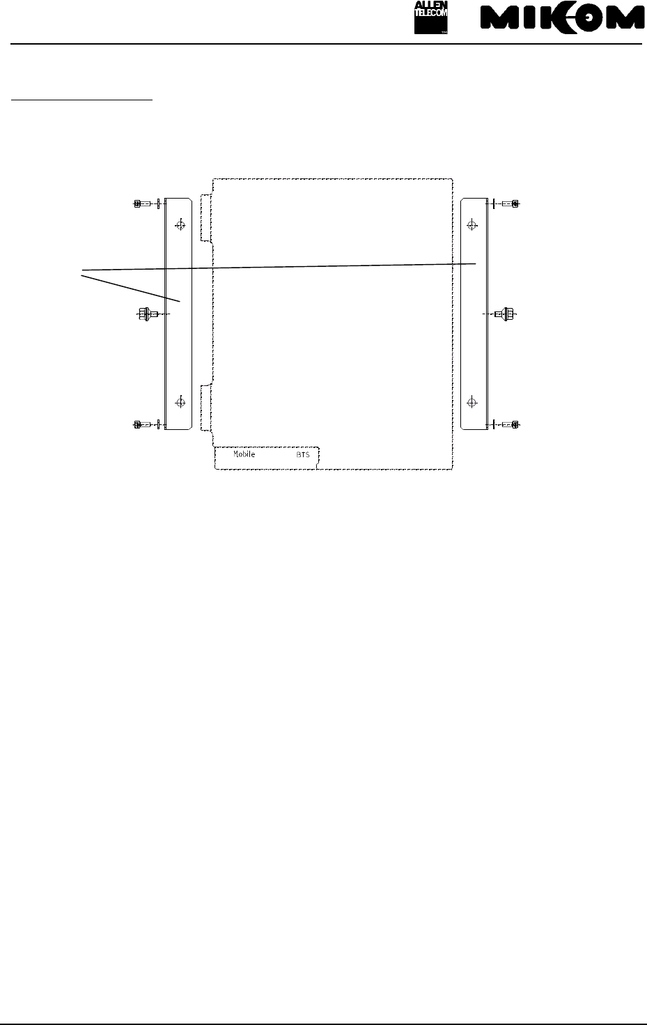
Mounting procedure:
Dismount the mounting brackets first. They are screwed tight to the housing with four socket
head cap screws M8.0x16 (see figure below) and two tire bolts.
figure 6-2 Wall mounting brackets
Use the wall mounting sheet to mark the position of the drilling holes. Drill 4 holes and screw
the mounting brackets to the wall. Attach the upper two socket head cap screws M8.0x16 to
the Repeater housing. Now it is possible to hang the Repeater into the mounting brackets. Fix
then the lower two socket head cap screws M8.0x16 and the 2 tire bolts.
F Note: The unit is heavy-weight. Make sure that a suitable mounting surface is
used. Only adequate manpower is allowed to handle the system.
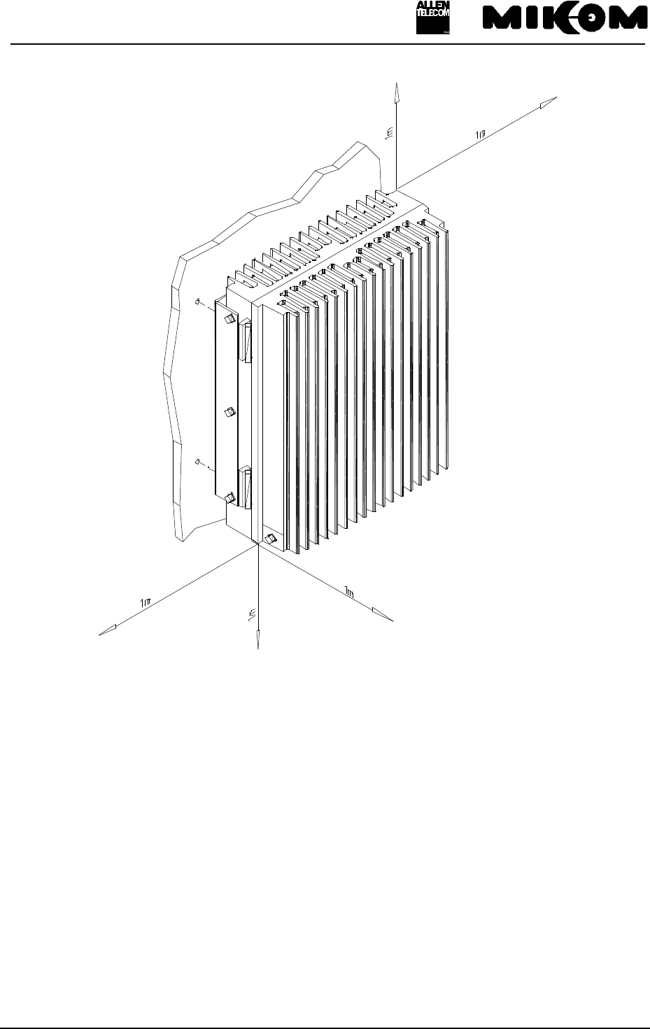
The installation position of the Repeater follows from the installation drawing, see figure 12-1
Installation drawing of the Repeater. Make sure that there is free access to the electrical
connections. The allowed bending radius of the connected cables must not be exceeded.
Furthermore the Repeater shall be mounted in a way that there is free access to the individual
units inside the cabinet, while the door of the Repeater is open.
Therefore keep a clearance distance of 1 m on each side, above and below the unit.
See following figure 6-3 Clearance distance.
mounting brackets
User’s manual for Remote Unit MOR701B Power
M0069A0A.doc Id.-No 151154 Page 44 23-June-99
figure 6-3 Clearance distance
User’s manual for Remote Unit MOR701B Power
M0069A0A.doc Id.-No 151154 Page 45 23-June-99
6.2 Electrical installation
FNote: ESD precautions have to be observed! Before working inside the cabinet
use the available grounding system to connect ESD protection measures.
The electrical installation has to be performed in accordance with the
safety regulations of the local authorities. Due to safety reasons the
electrical installation must be performed by qualified personnel. The
cover of this unit should not be opened while power is applied.
Subsequent installation, commissioning and maintenance activities that
require the unit to be powered with the cover open shall only be carried
out by suitably qualified personnel
6.2.1 Grounding
Grounding has to be performed by all means. Therefore a grounding bolt is provided at the
cabinet. An earth bonding cable will be mounted in the factory and will be delivered with the
unit. Don’t use the grounding screw for connecting external devices.
The complete grounding kit is part of the delivery schedule.
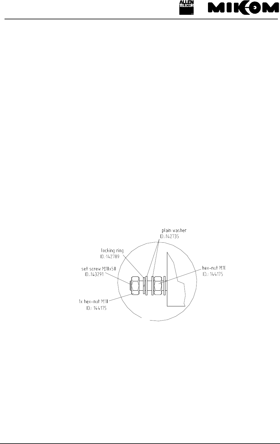
figure 6-4 Grounding kit
User’s manual for Remote Unit MOR701B Power
M0069A0A.doc Id.-No 151154 Page 46 23-June-99
6.2.2 Power connection
Before connecting electrical power to the Repeater grounding has to be performed. The
Repeater is equipped with a firmly connected power cord. Due to safety reasons the power
supply lead of the Repeater has to be protected with two 8 A fuses, type MT. In the event the
length of the power cord should not be sufficient it can be replaced by a longer cable.
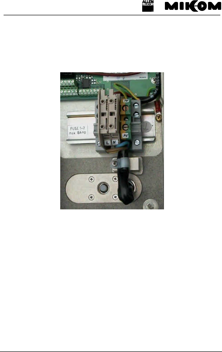
figure 6-5 Screw terminal
F Note: If the power supply lead has to be replaced use a cable of the same quality.
6.2.3 Connection of the antenna cable
The Repeater has a female antenna connector 7/16 (or N with adapter). For mounting the
corresponding cable connector we recommend to refer to the applicable documentation of the
respective connector manufacturer. The bending radius of the antenna cable must remain
within its specification. This will warrant proper operation of the system; otherwise changes
in the electrical behaviour of the cable might occur which could cause malfunction of the
Repeater system.
F Note: It is sufficient to fix the 7/16 (or N) antenna connector hand-screwed.
Any use of a tool (like tongs) might cause damage to the connector and
thus lead to malfunctioning of the Repeater.

User’s manual for Remote Unit MOR701B Power
M0069A0A.doc Id.-No 151154 Page 47 23-June-99
6.2.4 Connecting fibre optic cables
The standard transmission of the optical signals is carried out by means of an optical fibre pair
for each Remote Unit.
F Note: Extreme care should be taken when connecting and disconnecting the
fibre optic cable. Scratches and dust significantly affect system
performance and may permanently damage the connector, necessitating
re-termination. Always use protective caps on fibre optic connectors and
receptacles when not used.
The structure of the cable is not critical. However, demands of the site as for example rodent
protection and so on have to be kept in mind.
The optical fibre is a single mode fibre. The type is E9/125 with the following minimum
requirements.
Attenuation < 0.3 dB/km @ 1300 nm
Dispersion < 3.5 ps/nm*km @ 1300 nm
The allowed bending radius of the optical fibres must be kept by all means at any time.
The pig tails for the connection between Master and Remote Unit must have a sufficient
length. A protection for the feeding into units has to be given.
The system attenuation of the optical fibres including the connectors must not exceed 10 dB.
Less than 5 dB is desired.
The system attenuation and the attenuation of the opical components have to be determined.
This can be achieved by measuring the attenuation and the reflection with an appropriate
measuring instrument. For pig tails a total value of < 0.4 dB ( measured to a reference plug )
can be assumed due to the dead zone of the reflectometre. These measurements have to be
made with a sufficient length of optical fibre in front of and behind the device to be measured.
The fibre cables should be terminated with the same type of connector (DIN 8° or SC/APC
8°) as is used in the unit. The fibre optic cables are connected to the optical Transceiver and
receiver.
F Note: Angled connectors are not compatible with straight optical connectors;
non-compatibility of connectors will result in permanent damage to both
waiting connectors.

User’s manual for Remote Unit MOR701B Power
M0069A0A.doc Id.-No 151154 Page 48 23-June-99
Before connecting the fibre cables, follow the procedures below to ensure proper
performance. It is important that these procedures be performed with care:
1. Remove fibre optic protective caps.
2. Do not bend the fibre optic cable in a tight radius (<4 cm) as this may cause cable damage
and interrupt transmission.
3. Using high-grade alcohol and lint-free cotton cleaning swabs, clean the end of the fibre
optic cable that will be inserted in the optical connectors on the donor interface box.
4. Blow the end dry with clean, dry compressed air.
5. Vigorously blow out the laser receptacle with clean, dry compressed air to remove any
particulate matter.
6. Connect the fibre optic cables by inserting the cable end into the laser receptacle and
aligning the key (on the cable end) with the keyed slot.
7. Do not use any index matching gels or fluids of any kind in these connectors. Gels are
intended for laboratory use and attract dirt in the field.

User’s manual for Remote Unit MOR701B Power
M0069A0A.doc Id.-No 151154 Page 49 23-June-99
7 Setting to work
7.1 Preparation
F Note: It is not allowed to operate the Repeater without termination of the
antenna connections! The termination can be performed by the antenna
connection as well as a dummy load or the 50-Ohm-terminated connection
of a measuring instrument.
Before bringing the Repeater system into service it is necessary to measure the antenna
isolation. The Repeater system has its maximum available gain when the attenuation is set to
zero. On site the maximum allowed gain is 15 dB less than the value of the antenna isolation.
In order to check the function of the Repeater system on site it is advisable to operate the
Repeater system with 50 Ohm termination. This makes it possible to set the necessary gain
and to test the set value without the necessity of transmitting on air.
In order to perform settings the Repeater has to be opened. Please ensure not to damage the
seals which are on the modules situated on the RF modules inside of the Repeater, because
this would lead to risk the success of warranty claims.
After taking the Repeater into service following signals occur during the boot process.
Internal
LED L1 Internal
LED L2 Internal
LED L3 Cause
green red green red green
- - - - ll Power on state,
Software boot starts
ll Flashes
red short
time
ll Flashes red
short time ll Software boot starts
ll ll ll Software is running
table 7-1 LED indication
User’s manual for Remote Unit MOR701B Power
M0069A0A.doc Id.-No 151154 Page 50 23-June-99
7.2 Setting of operational parameters
Attenuation of the Repeater can be set manually, locally or remotely. Frequency can be set
locally and remotely.
There are three different possibilities to set the operational parameters:
-manual settings by means of rotary switches
-local control via RS232 interface and PC
-remote control via Master Unit
7.2.1 Manual setting of the attenuation by means of rotary switches
The manual mode allows the user to set the required attenuation by means of rotary switches.
With a small screwdriver, which fits through the long holes of the RF modules, the values can
be adjusted by turning the switch carefully to the desired position.
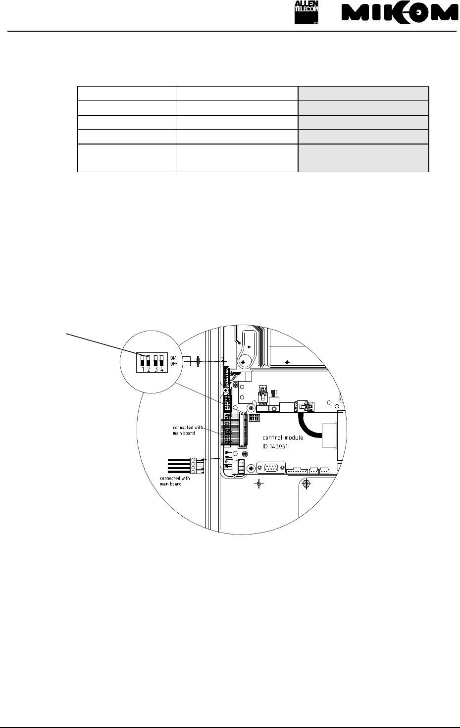
F Note: To enable manual settings of parameters the mode switch (DIP-Switch 1)
has to be changed from OFF to ON.
The DIP-Switch is mounted on the control module, located on the left-hand side of the
Repeater.
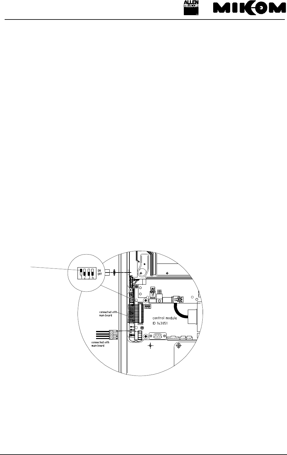
figure 7-2 Position of the DIP-Switch 1
DIP-Switch 1
User’s manual for Remote Unit MOR701B Power
M0069A0A.doc Id.-No 151154 Page 51 23-June-99
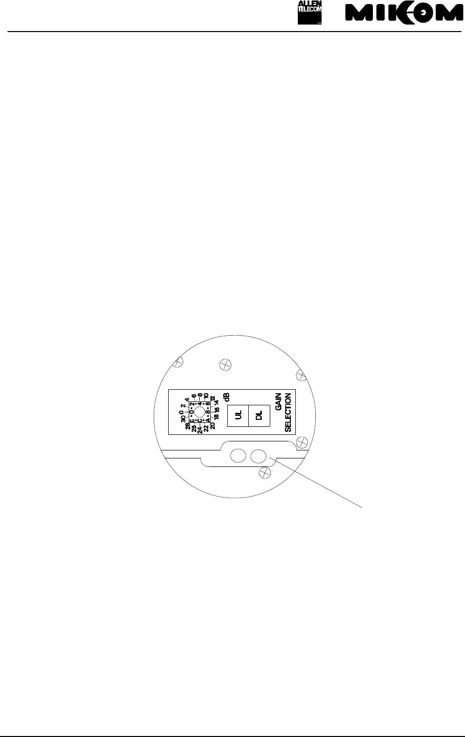
The gain can be set by introducing attenuation into the amplifier chain. By using a rotary
switch the attenuation can be adjusted locally in the range from 0 dB to 30 dB maximum in
steps of 2 dB. The attenuation can be set for the UL and DL path separately.
The rotary switches are mounted on the mother board. These switches are accessible through
the long hole between the two RF modules ( see figure 7-3 Position of the rotary switches).
They can be adjusted easily by means of a small screwdriver.
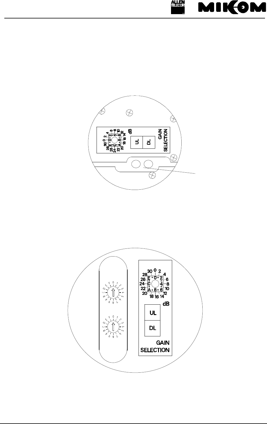
figure 7-3 Position of the rotary switches
A label on the RF module, located next to the rotary switch, illustrates the usage of the rotary
switch (see figure 7-4 Rotary switches and label).
figure 7-4 Rotary switches and label
F Note: Gain can be changed independently for the uplink and downlink path.
DIP-Switch configuration:
long hole
User’s manual for Remote Unit MOR701B Power
M0069A0A.doc Id.-No 151154 Page 52 23-June-99
DIP-Switch ON OFF (default values)
1manual auto
2remote mode local mode
3n.c. n.c.
4software download
manually controlled software download
controlled by software
table 7-5 DIP-switch configuration
7.2.2 Settings via personal computer as terminal
Instead of manually setting operational parameters via rotary switches it is also possible to use
the functions of the control module. The local mode for settings via PC has to be set.
Therefore the DIP-Switch 2 has to be at position OFF.
figure 7-6 DIP-switch 2 for local mode
DIP-Switch 2
User’s manual for Remote Unit MOR701B Power
M0069A0A.doc Id.-No 151154 Page 53 23-June-99
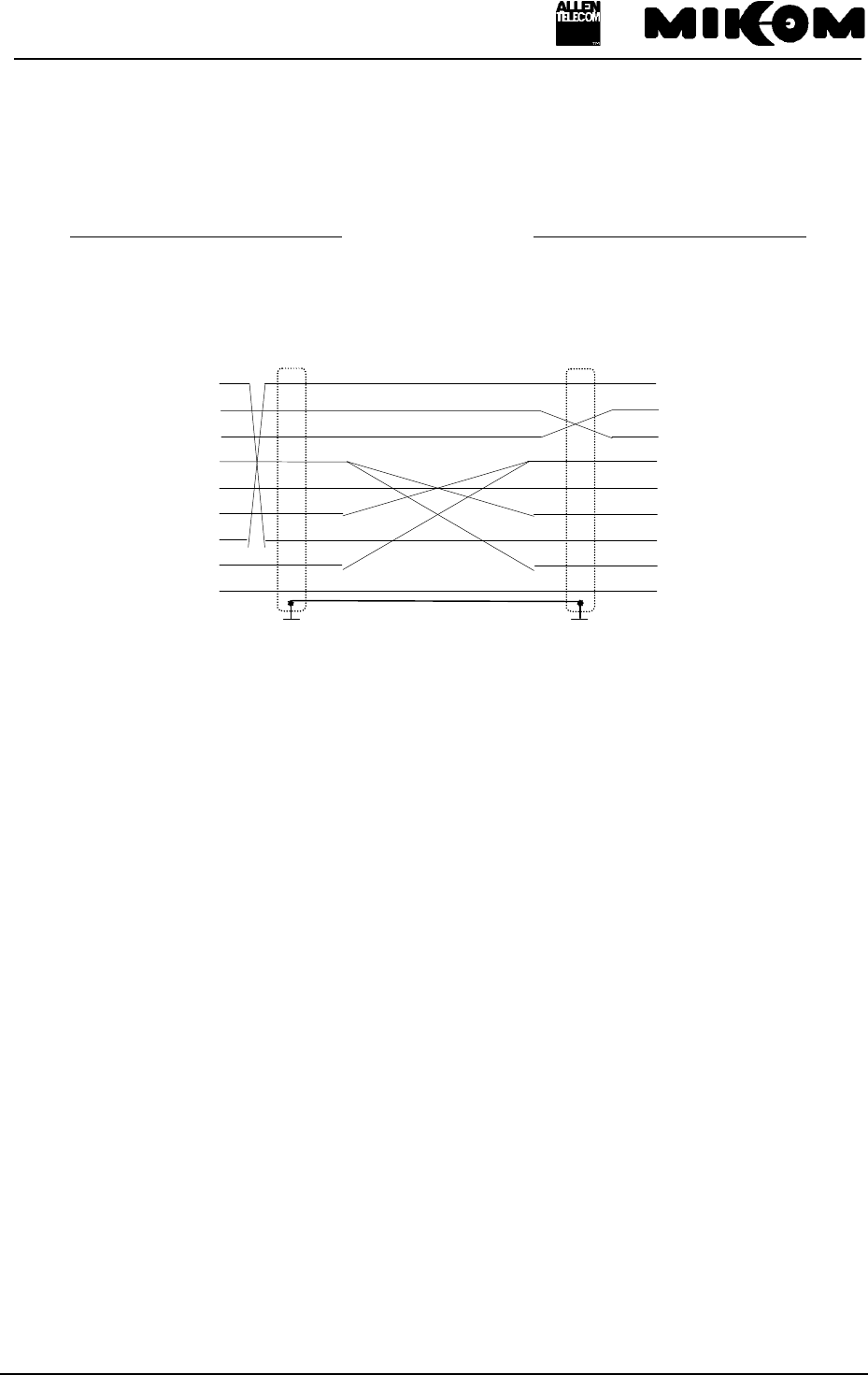
A VT100 terminal or a PC with VT100 emulation can be connected to the control module
SM2009 by a standard RS232 cable, if necessary in connection with an adapter 9 to 25.
Cable Connections PC - Control Module SM2009
9 contact SUB - D- Connector 9 contact SUB - D- Connector
male male
PC RS 232
MOR701B Power
PIN PIN
1 ) ( 1
2 ) ( 2
3 ) ( 3
4 ) ( 4
5 ) ( 5
6 ) ( 6
7 ) ( 7
8 ) ( 8
9 ) ( 9
The following communication mode between control module and VT100 is set initially.
9600 baud - 8 bit - no parity -1 stopbit
These settings can only be changed after connection of the terminal.
Modifications are possible by software commands.
F Note: Settings on the Repeater can be performed after the following procedure
only.

User’s manual for Remote Unit MOR701B Power
M0069A0A.doc Id.-No 151154 Page 54 23-June-99
After connecting the PC to the Repeater, following procedure is necessary to get access to the
program.
MIKOM REPEATER MOR701B - SM2009 - SW: REP1007V1.11
ENTER <.> <CR> TO LOGIN
1. Step: Type the two keys ( . ) FULLSTOP and (↵) ENTER
You have to type the keys:
2. Step: ENTER USER ID
You have to enter: UserID1 ↵
F Note: The input is case sensitive, no blanks. After three mistrial follows
disconnection.
3. Step: ENTER PASSWORD
You have to enter: P-word1 ↵
F Note: The input is case sensitive, no blanks. After three mistrials follows
disconnection.
7.2.3 Remote control via Master Unit
The Remote Unit can be set remotely through the optical interface by devices connected to the
Master Unit.
↵↵
.

User’s manual for Remote Unit MOR701B Power
M0069A0A.doc Id.-No 151154 Page 55 23-June-99
8 Trouble shooting
All Repeaters are factory-set to „Power down disabled“ status, this means the channel group
is active. To switch off the channel group use the software command „PWRDOWN enabled“.
(You find a detailed description in the software manual.)
8.1 Error indication
l = LED on
- = LED off
Internal
LED L1 Internal
LED L2 Internal
LED L3 Cause
green red green red green
- - - - -
No power.
Check presence of power at
the input; replace fuse
according to chapter 9.3,
check battery backup module
l l l Indicates a
summary failure
8.2 Boot process
Following signals occur during boot process.
Internal
LED L1 Internal
LED L2 Internal
LED L3 Cause
green red green red green
- - - - ll
Power on state, Software boot
starts
ll Flashes red
short time ll Flashes red
short time ll Software boot starts
ll ll ll Software is running

User’s manual for Remote Unit MOR701B Power
M0069A0A.doc Id.-No 151154 Page 56 23-June-99
8.3 Alarm monitoring with the STATUS HIST command
Check alarms with ‘status hist‘ command.
1. If a hardware module is damaged, replace corresponding hardware module.
2. Minor alarms with no influence on the system can be cancelled by confirming the alarm
with the ‘alarmackn’ command, e.g., ALC active, VSWR, RSSI or DOOR OPEN.
3. If all alarms have been acknowledged the summary error LEDs will be set back to green
indication.
4. In case of mains power failure the contents of the actual STATUS HIST list is lost.
For a complete list of available alarms, see table 3-4 List of all available alarms
8.4 Power supply
The output voltage is factory set and should not be changed.
8.5 General remarks
• After a software download previous user settings ( data default values ) might be
overwritten. Before you start a software download save the set values for:
- centre frequency
- attenuation
- ALC threshold
• If an ALC or AMPBIAS alarm occurs during installation or commissioning an user error
might be the cause, due to wrong measurements.
User’s manual for Remote Unit MOR701B Power
M0069A0A.doc Id.-No 151154 Page 57 23-June-99
9 Maintenance
9.1 General
F Note: The Repeater does not require preventative maintenance measures.
It is only recommended to replace the RAM/RTC battery
after three years usage as a prophylactic measure. The
nominal lifetime of these batteries is five years under
normal environmental conditions.
In the event of a malfunction it is advantageous to check
the status of the antenna systems as well as the continuity
of the entire cabling including connectors, before replacing
the modules.
Maintenance on the Repeater shall be performed only by
replacing modules. Soldering on printed circuit boards
shall be avoided. In order to sustain warranty take care not
to damage unintentionally the seals on the modules.
The spare part list, consequently, contains only units,
which can be replaced without tuning or complex
soldering work.
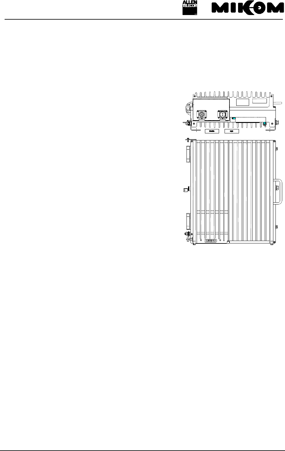
figure 9-1 Top view of the Repeater
F Note: Defect parts should only be replaced by original parts from MIKOM.
All interventions inside the housing are at one’s own risk.
During maintenance ensure that the Repeater has been disconnected from
mains.
Open the lock at the connector panel and remove the cover plate. To open the housing use a
Torx key and unscrew the four Torx screws.
9.2 Replacement of the fuses (mains)
The mains cable is protected with two fuses F1 and F2 8A type MT. They are accessible
inside of the Repeater at the fuse terminal on the right-hand side. Open the screw plug for the
fuse and take out the fuse.
F Note: Use only fuses of the same type and the same rating when replacing!
See figure 9-2 Fuse terminal for position of the 8A fuses.
User’s manual for Remote Unit MOR701B Power
M0069A0A.doc Id.-No 151154 Page 58 23-June-99
figure 9-2 Fuse terminal
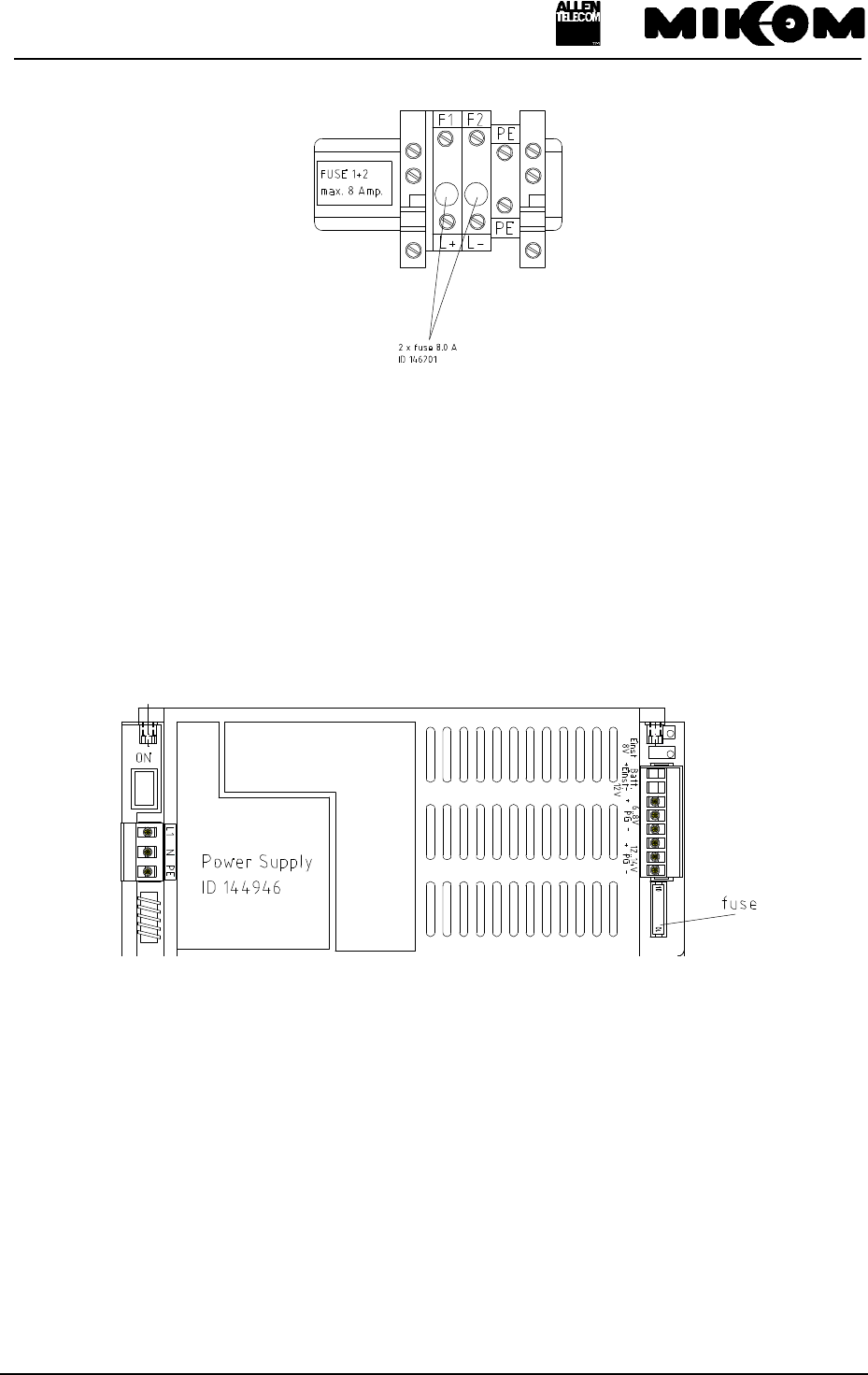
9.3 Replacement of the power supply fuse
Each power supply is protected with a fuse 10 A / 35 V. The fuse is mounted outside of the
power supply housing.
F Note: Use only fuses of the same type and the same rating when replacing!
figure 9-3 Position of power supply fuse
9.4 Replacement of the mains cable
The Repeater will be delivered with a firmly connected mains cable.
In case the length of the delivered mains cable should not be sufficient or in case of a defect,
the mains cable can be replaced.
F Note: Disconnect Repeater from mains first.
User’s manual for Remote Unit MOR701B Power
M0069A0A.doc Id.-No 151154 Page 59 23-June-99
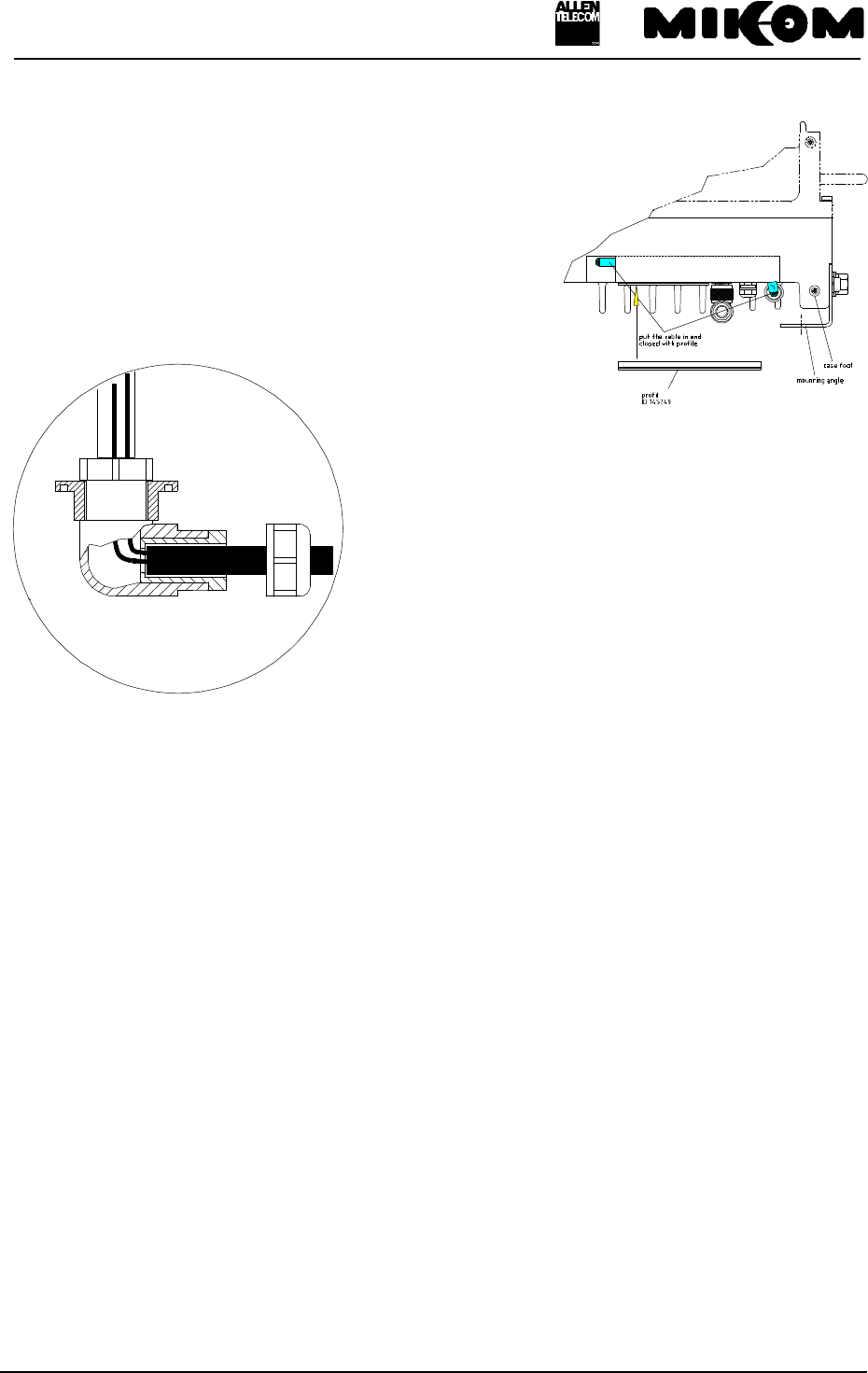
Remove the clamping profile at the outside of the housing
by pulling at the mains cable. Open the PG9 threaded joint
with a spanner size 17. Inside the housing remove the
plastic cable clip by unscrewing the tallow-drop screw.
Then use a small screwdriver and open the screws of the
fuse terminal.
Now the mains cable
can be removed by
pulling at the cable. For the installation of a new cable
strip the isolation of a new cable to the length of 18 cm.
Put the screw of the cable gland over the cable then use
the joint rubber and pull it over the cable. This will
guarantee a tight connection. Now insert the cable.
Inside the housing pull an insulated tube with the length
of 8 cm over the wires. Now close the PG9 threaded
joint. Screw the wires to the fuse terminal. Fix the cable
with the plastic cable clip.
Put the cable in the guide shaft and close it with the clamping profile.
9.5 Replacement of the RAM / RTC battery
The RAM / RTC battery of the control module has to be replaced in case of memory loss or
as a preventive measure after approximately three years usage. The RAM / RTC battery is
mounted on the left-hand side of the Repeater underneath the dummy battery backup module
First remove the whole dummy battery backup module ( see figure 9-5 Position of dummy
battery backup module ), which is plugged into the control module. Take off the Lithium
battery by means of a small screwdriver, placed between the battery and the battery socket.
The type of the battery is CR 2450 Lithium 3 V / 500mAh, manufacturer is RENATA.
After replacement of the RAM battery, the control module has its basic settings, date and time
have to be set to the actual value.
User’s manual for Remote Unit MOR701B Power
M0069A0A.doc Id.-No 151154 Page 60 23-June-99
figure 9-4 Position of RAM/RTC battery
F Note: Before replacing the battery, disconnect the Repeater from mains.
Observe the rules for changing Lithium batteries. Wrong connection or
treatment may result in bursting of the battery and dissemination of
hazardous substances.
Don’t try to charge this battery.
9.6 Replacement of the dummy battery backup module
The dummy battery backup module is accessible after opening the housing on the left-hand
side.
Before you are able to remove the module from the socket, release the three snap-in lockings.
RAM/RTC battery
dummy battery backup module
User’s manual for Remote Unit MOR701B Power
M0069A0A.doc Id.-No 151154 Page 61 23-June-99
figure 9-5 Position of dummy battery backup module
9.7 Replacement of the duplexer
This description is valid for the one channel configuration of the Repeater only. For different
configurations refer to the assembly guide for the Repeater.
Remove the semi-rigid cables which connect the DL Output with the feed forward amplifier
by loosening the SMA connector. Use a torque wrench. Then remove the semi-rigid cable
from the mother board.
It is recommended not to remove the amplifier which is mounted on the backside of the
duplexer. A new duplexer will be delivered with a premounted amplifier.
The cables have to be connected as shown below.
figure 9-6 Cable configuration of the duplexers
dummy battery backup module
G0850M1
User’s manual for Remote Unit MOR701B Power
M0069A0A.doc Id.-No 151154 Page 62 23-June-99
Unscrew the four counter sunk screws M3 at the connector panel of the Repeater. See figure
9-7 Connector panel layout.
figure 9-7 Connector panel layout
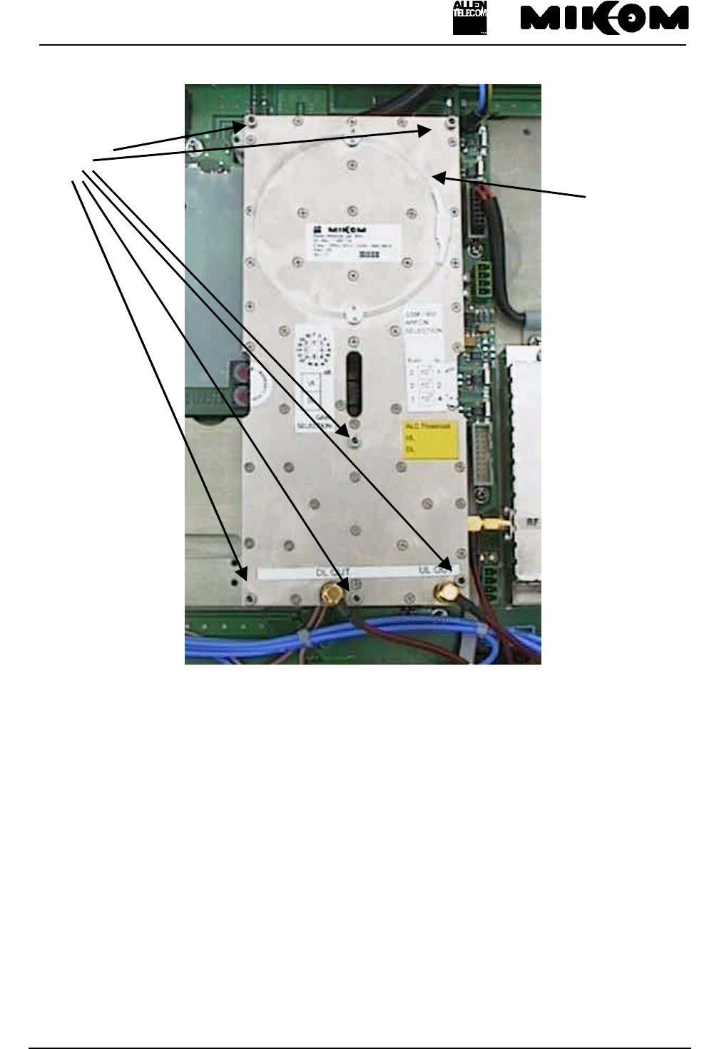
9.8 Replacement of RF modules
To remove the RF modules, disconnect the SMA connectors by means of a torque wrench.
If the Repeater is equipped with TDMA modules, the external filter on top of the modules
must be dismounted beforehand. The external filter box covers two of the socket head cap
screws the TDMA module is fixed with.
Unscrew the socket head cap screw on top of the external filter box, pull the box carefully off
and continue the dismounting procedure as described below.
Unscrew six socket head cap screws by means of a hex socket key.
Pull carefully by means of the mounting strap, fixed on the module (see figure 9-8 Top view
of an RF module) and take off the module.
G0850Z0
User’s manual for Remote Unit MOR701B Power
M0069A0A.doc Id.-No 151154 Page 63 23-June-99
*: TDMA and CDMA modules are equipped with mounting straps on the left and on the right side.
figure 9-8 Top view of an RF module
Connecting the RF modules depends on the number of channels your Repeater is equipped
with, i.e. with one up to four channels. Each configuration has got a different cabling. See
assembly guide of the channel modification kits for the cabling of the RF modules dependent
on the configuration of the Repeater.
Mounting
strap *
Socket head cap
screws
User’s manual for Remote Unit MOR701B Power
M0069A0A.doc Id.-No 151154 Page 64 23-June-99
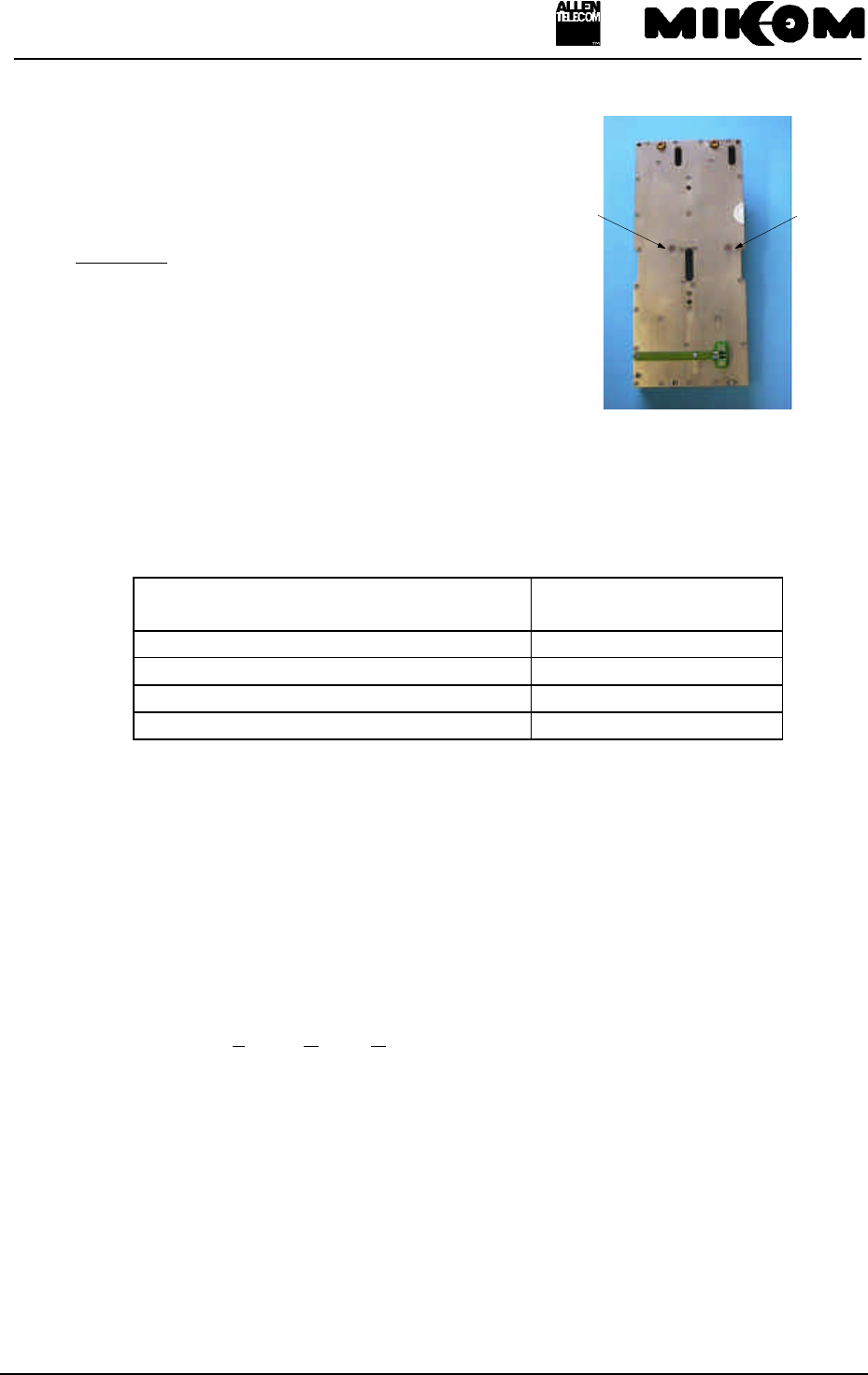
For the exchange of an RF module
or the installation of a new RF
module, the slave address of the synthesizer
has to be set. This can be done by means
of hex-coded rotary switches mounted
on the lower side of the modules
(figure 9-9 Position of hex coded rotary switches).
figure 9-9 Position of hex
coded rotary switches
The synthesizer address must be set like shown in the following table:
Address
RF module UL DL
Channel one 0 1
Channel two 2 3
Channel three 4 5
Channel four 6 7
table 9-10 Address of synthesizer
Instructions for band selective modules with variable bandwith can be found in a seperate
document.
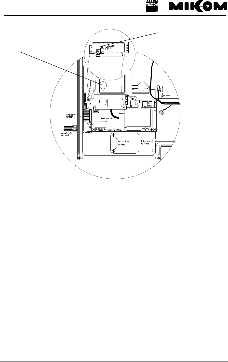
9.9 Replacement of the control module SM 2009
The control module is a Printed Circuit Board situated on the left-hand side of the Repeater.
Disconnect the DC cable from power supply.
Disconnect the flat cable.
Remove the battery backup module and remove the Tyrap which is fixed to the control
module.
Take off the whole control module completely with mounting plate by unscrewing four tallow
drop screws M4.
Hex-coded rotary switch
for UL
Hex-coded rotary switch
for DL
User’s manual for Remote Unit MOR701B Power
M0069A0A.doc Id.-No 151154 Page 65 23-June-99
For mounting proceed in reverse order.
Position of the control module in the Repeater is illustrated in figure 9-11 Position of control
module.
figure 9-11 Position of control module
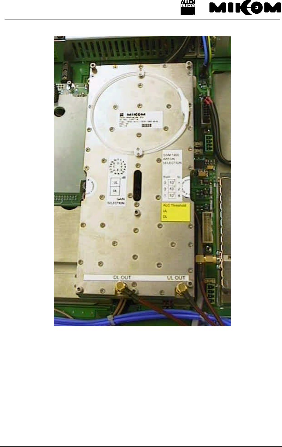
9.10 Replacement of power supplies
F Note: Ensure that mains are disconnected.
There are three power supplies mounted in the Repeater housing, two on each side. Open the
Repeater to get access to the devices.
Remove all connected cables from the clamps of the power supply. Try to loose the plug by
means of a small screwdriver placed between the plug and socket.
ON
Fuse 10A / 35V
figure 9-12 Power supply

User’s manual for Remote Unit MOR701B Power
M0069A0A.doc Id.-No 151154 Page 66 23-June-99
The power supply is fixed to the Repeater housing by means of two special nuts M4. After
loosening the screws the power supply can be removed. To open these screws a special key
with a spherical head is required (This key is part of the delivery). Place a small screwdriver
between the Repeater housing and the power supply to loose the device.
figure 9-13 Position of special-nut M4
F Note: Don’t forget to put heat conducting paste on the mounting side for
installation of a new power supply. Use the conducting paste, which is
included in the spare parts kit.
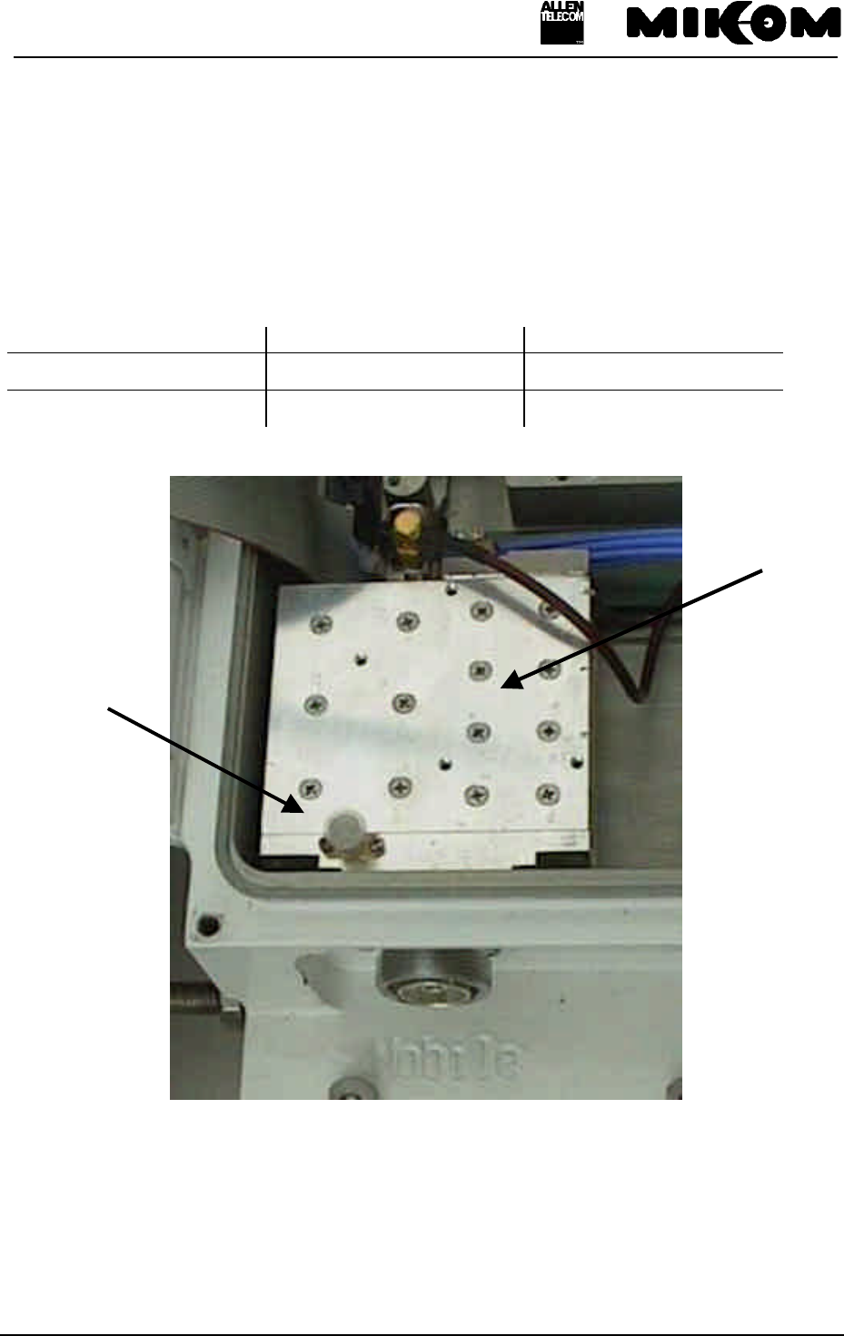
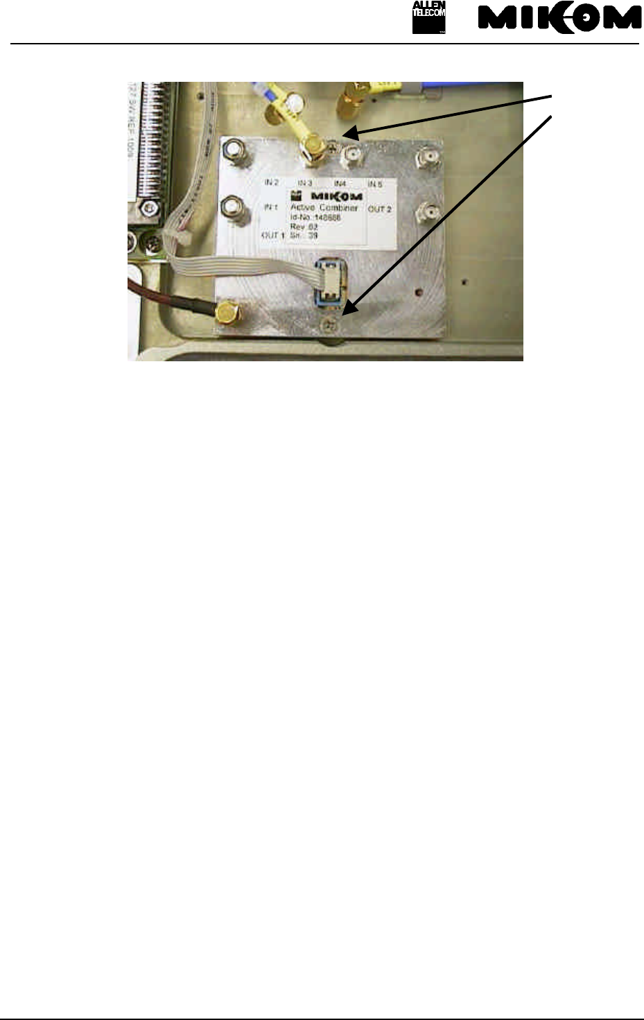
9.11 Replacement of Active Combiner modules
The Active Combiner modules are mounted on both sides of the Repeater.
Disconnect all SMA connectors by means of a torque wrench.
Unscrew two counter sunk screws M3x20mm. See figure 9-14 Position of counter sunk
screws on Active Combiner.
User’s manual for Remote Unit MOR701B Power
M0069A0A.doc Id.-No 151154 Page 67 23-June-99
figure 9-14 Position of counter sunk screws on Active Combiner
The cabling of the Active Combiners depends on the configuration of the Repeater. For
correct connections see assembly guide for the channel modification kits.
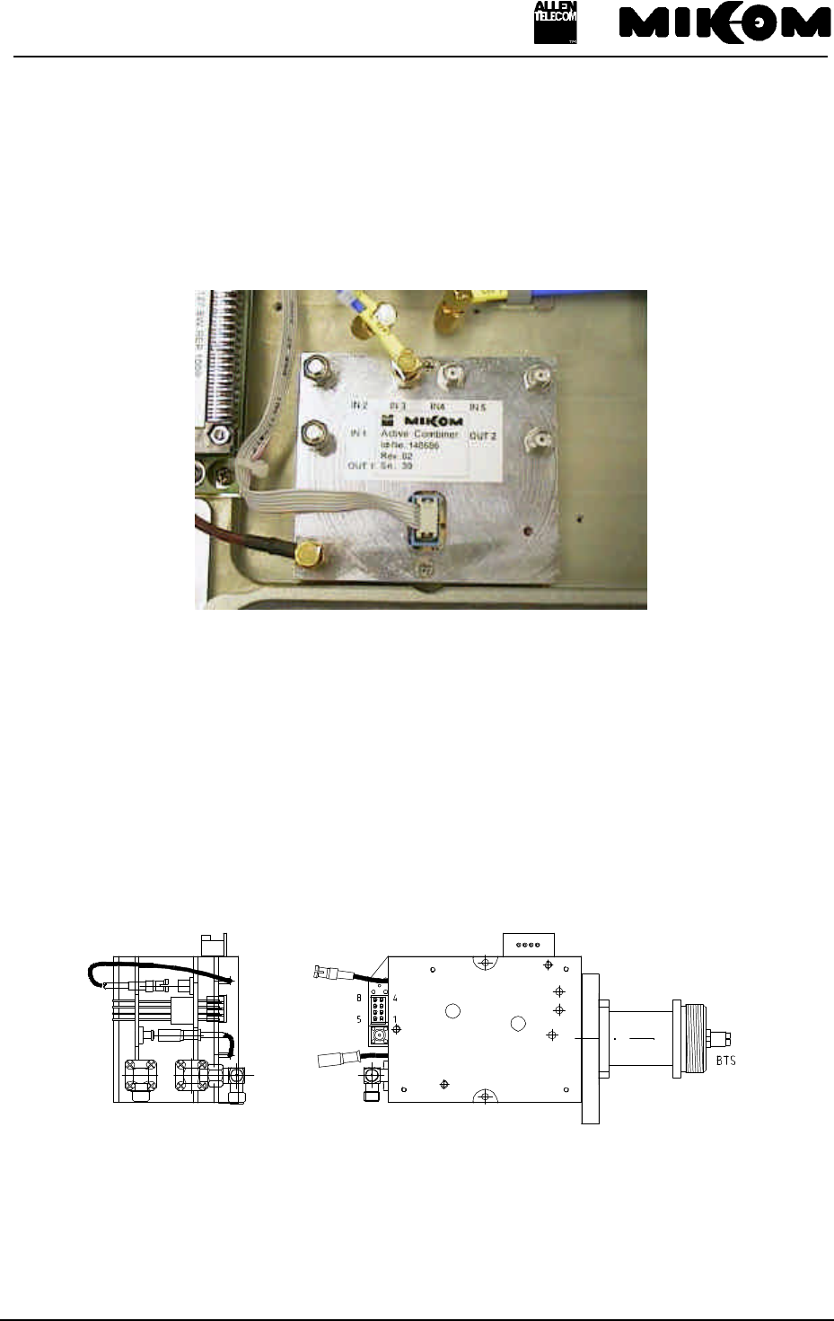
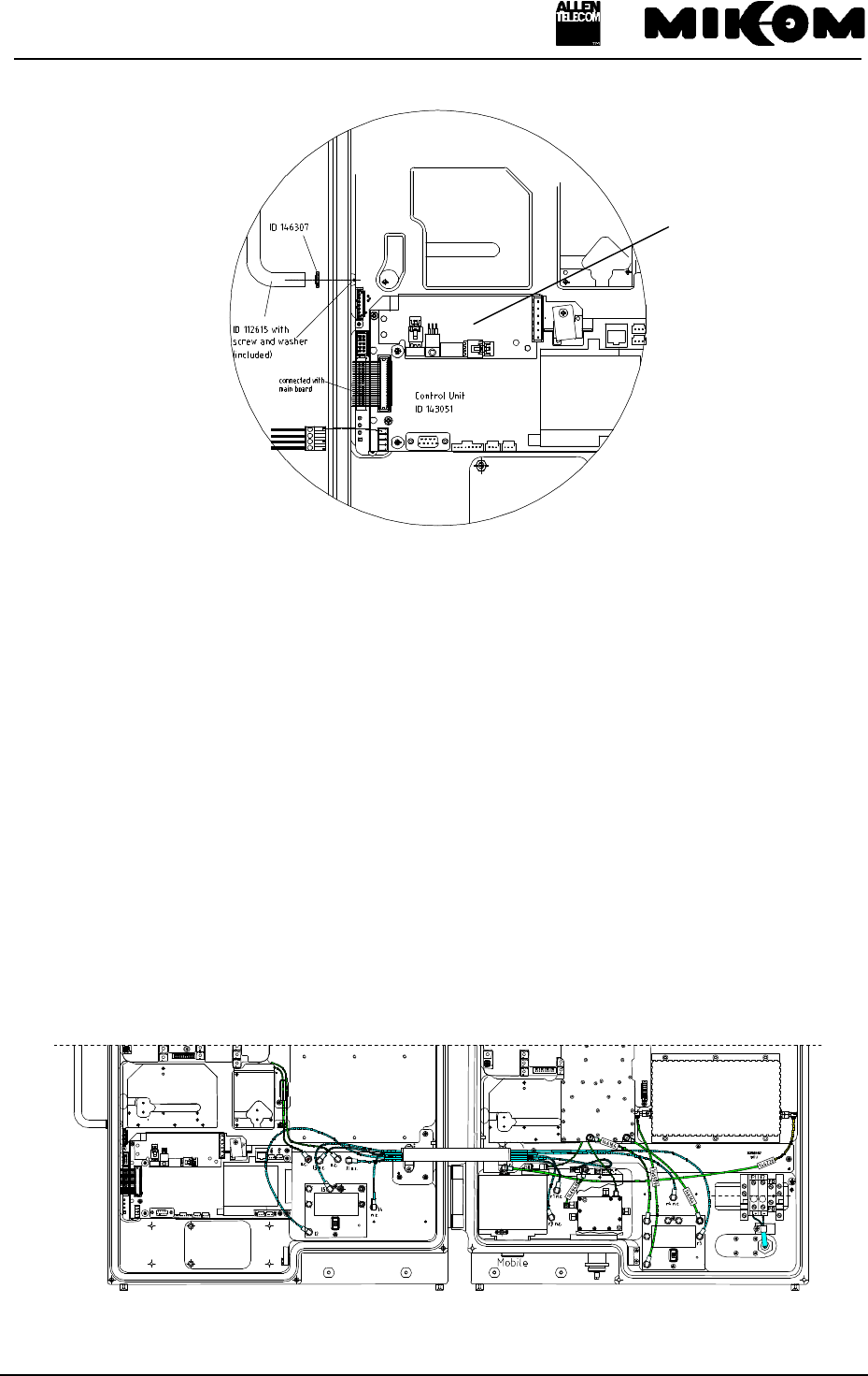
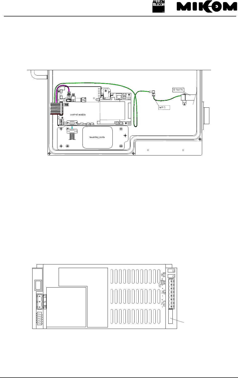
9.12 Replacement of feed forward amplifier
There is one amplifier mounted on the right-hand side of the Repeater. It is fixed to the
housing by means of 6 socket head cap screws M4x25.
A special reset board is connected to the 15 pole SUB-D connector. (see figure 9-15 Position
of the feed forward amplifier reset board)
This reset board is part of the feed forward amplifier. A new feed forward amplifier will be
delivered with a premounted reset board.
counter
sunk
screws
User’s manual for Remote Unit MOR701B Power
M0069A0A.doc Id.-No 151154 Page 68 23-June-99
figure 9-15 Position of the feed forward amplifier reset board
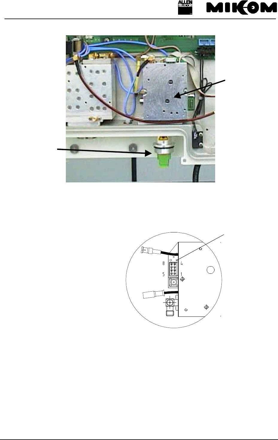
Remove the ready made cable which is plugged to the 15 pole SUB-D connector of the reset
board. Unscrew the screw clip first.
The SMA connectors can be removed only after dismounting the amplifier.
Position of the feed forward amplifier is illustrated in figure 9-16 Position of feed forward
amplifier (Right-hand side of Repeater).
figure 9-16 Position of feed forward amplifier (Right-hand side of Repeater)
Reset board
feed
forward
amplifier
User’s manual for Remote Unit MOR701B Power
M0069A0A.doc Id.-No 151154 Page 69 23-June-99
9.13 Replacement of the FSK modulator
To remove the FSK modulator disconnect all connected cables. Remove the two tallow drop
screws which connect the FSK modulator with the MFY1319. The device can be removed.
figure 9-17 FSK modulator
9.14 Replacement of the Transceiver MFY1319
To remove the Transceiver dismount the FSK modulator which is fixed with two screws M3
on top of the Transceiver. Disconnect all cables. Then unscrew the four counter sunk screws
M3 at the connector panel. Now you can remove the Transceiver MFY1319.
figure 9-18 Installation position
Transceiver MFYFSK modulator

User’s manual for Remote Unit MOR701B Power
M0069A0A.doc Id.-No 151154 Page 70 23-June-99
10 Spare parts list
The following list contains all parts available for the MOR701B Power . The configuration of
the delivered unit meets the requirements of the customer and can differ depending on the
state of delivery.
Designation Id.-No.
Mounting material 150521
Basic Module 148702
Extension Module 148705
Basic Module TDMA 148703
Extension Module TDMA 148706
Basic Module CDMA 148704
Extension Module CDMA 148707
Basic Module var. BW 148714
Extension Module var. BW 148945
Conversion Module 5 MHz 148716
Conversion Module 15 MHz 148717
PCS Duplexer UL Input 1850.0 - 1885.0 MHz 144382
PCS Duplexer UL Input 1875.0 - 1910.0 MHz 144384
Feedforward Amplifier 1930 - 1990 MHz 148628
Transceiver MFY1319 DIN Connector 143094
Transceiver MFY1319 SC Connector 146616
FSK Modulator 10,7 MHz 145820
Power Supply 115 Vac ±15% 40 - 65 Hz USA plug 141230
Power Supply 230 Vac ±15% 14 - 65 Hz Ger plug 138305
Power Supply 230 Vac ±15% 14 - 65 Hz UK plug 142832
Power Supply 230 Vac ±15% 14 - 65 Hz no plug 144306
Power Supply 24Vdc no plug 145504
Power Supply 185 - 320 Vac 40 - 65 Hz no plug 148812
Power Supply ±42 - ±60 Vdc no plug 144946
Power Supply ±80 - ±130 Vdc no plug 145524
SW MOB100 V1.10 143055
Control Unit SM2009 143051
SW SLV1007 V1.01 146278
SW SLV1009 V1.04 147956
Manual SW SLV1009 V1.xx 148354
Dummy Battery Backup Module 143750
Battery Backup Module 143052
Sparepart Kit 146200
Wall mounting Kit 146179
Main Board 26V version 149778
Main Board 26V version 149777
Active Combiner DL 1930 - 1990 MHz 148685
Active Combiner UL 1850 - 1910 MHz 148887

User’s manual for Remote Unit MOR701B Power
M0069A0A.doc Id.-No 151154 Page 71 23-June-99
4-way-Splitter 150730
Termination Resistor 33167
Ready-made cable data 149936
Ready-made cable DC 149928
Ready-made cable data 148576
Ready-made cable DC 149648
Ready-made cable DC female headers 6 contacts 150753
4 External Alarms option Kit 147710
Adapter 7/16 male N female 112425
Mother board 147024
Manual for MOR701B Power 151154
Assembly guide for modification kits 151045
Modification Kit for one channel 149917
Modification Kit for two channels 149918
Modification Kit for three channels 149919
Modification Kit for four channels 149920
table 10-1 Spare parts list

User’s manual for Remote Unit MOR701B Power
M0069A0A.doc Id.-No 151154 Page 72 23-June-99
11 Configuration list
The actual configuration of the Repeater system has been entered on a separate list at
delivery. This configuration list is subject of the delivery schedule providing actual
information of part number, Id. number, serial number and revision status of the Repeater.
Whenever parts should be replaced the user is kindly asked to update the list.
See sample below:
Remote Unit MOR701B
Id.-No.: 147362 SN:
Part name Id.-No. Rev SN
Basic Module *** *** ***
Extension Module *** *** ***
Power Supply
Duplexer UL input
Feed Forward amplifier
Transceiver MFY1319
FSK Modulator 10.7 MHz
Control Unit SM2009
SW SLV100x
Battery Backup Module
Mother Board
SW MOB100
Connecting Board
Active Combiner
Date: _________________ QA: ________________________
figure 11-1 Sample of a configuration list
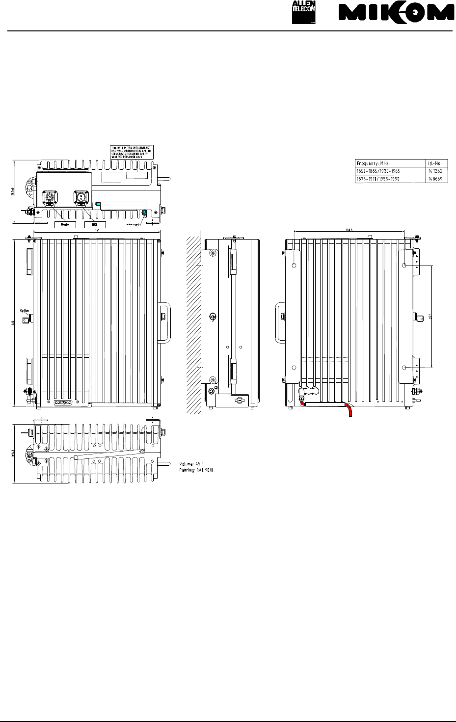
User’s manual for Remote Unit MOR701B Power
M0069A0A.doc Id.-No 151154 Page 73 23-June-99
12 Appendix
12.1 Installation drawing of the Repeater
figure 12-1 Installation drawing of the Repeater
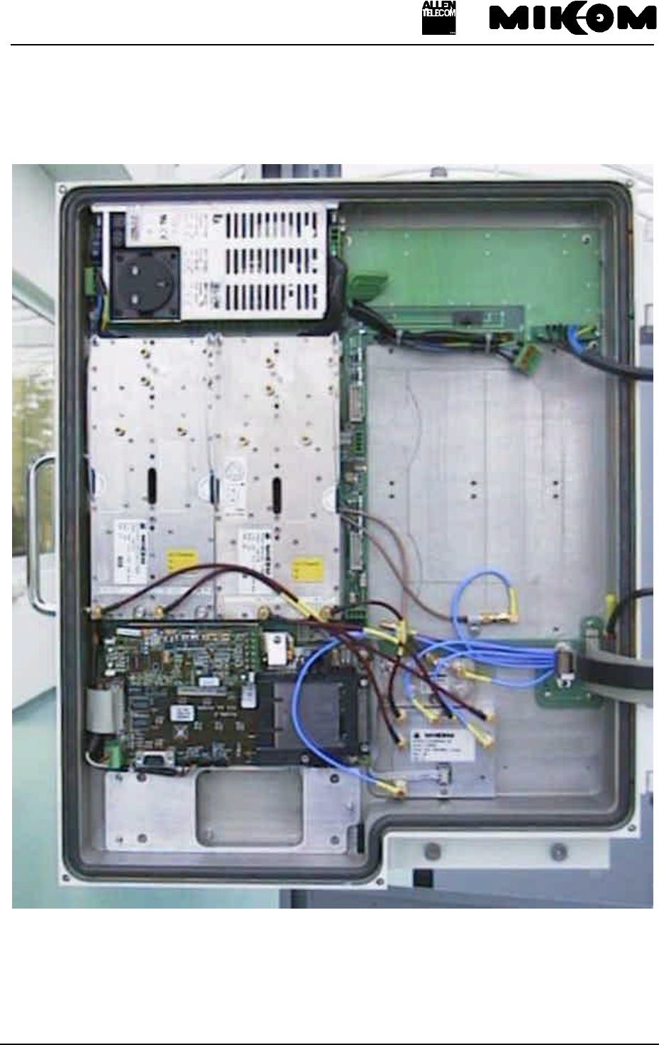
User’s manual for Remote Unit MOR701B Power
M0069A0A.doc Id.-No 151154 Page 74 23-June-99
12.2 Top view of the Repeater (left-hand side , four channel configuration)
figure 12-2 Top view of the Repeater (left-hand side, four channel configuration)
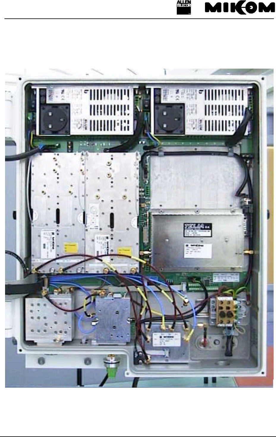
User’s manual for Remote Unit MOR701B Power
M0069A0A.doc Id.-No 151154 Page 75 23-June-99
12.3 Top view of the Repeater (right-hand side, four channel configuration)
figure 12-3 Top view of the Repeater (right-hand side, four channel configuration)
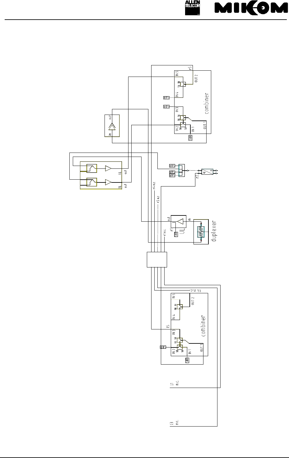
User’s manual for Remote Unit MOR701B Power
M0069A0A.doc Id.-No 151154 Page 76 23-June-99
12.4 One channel configuration –block diagram and cabling
figure 12-4 Block diagram of one channel Repeater
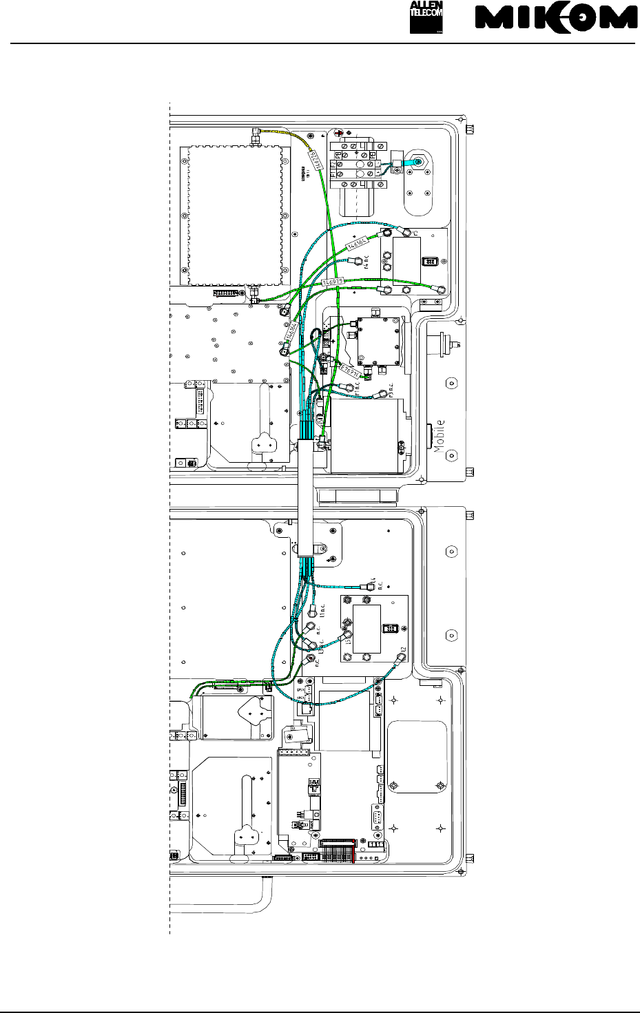
User’s manual for Remote Unit MOR701B Power
M0069A0A.doc Id.-No 151154 Page 77 23-June-99
figure 12-5 Cabling of one channel Repeater

User’s manual for Remote Unit MOR701B Power
M0069A0A.doc Id.-No 151154 Page 78 23-June-99
13 Index
A
Abbreviations 8
Active Combiner 20, 66
Address of MIKOM 11
Alarm monitoring 56
Alarms
External alarms 32
Handling of 28
Indication of 26
List of all alarms 28
ALC 26
Antenna connector 40
Antenna connectors 46
Antenna isolation 49
B
Battery backup 34
BITE 26
Boot process 55
C
Channel
Setting via PC 52
Clamping profile 59
Connector type
7/16 female 40
Contents of delivery 9
Control module 18
D
DIP-Switch 51
Dummy battery backup module 60
Duplexer 19, 61
E
EEPROM 18
Environmental and safety 38
ESD precautions 11
F
Feed forward amplifier 24
Fibre optic cable 47
FSK modulator 21
G
Gain
Local settings 25, 51
Setting via PC 52
Grounding 45
H
Health and safety warnings 10
I
I²C-Bus 18
Ident numbers 70
Installation
Electrical 46
Mechanical 42
Interfaces 18
RS232 18
International sales offices 12
L
LEDs 26
Local settings 50
M
Maintenance 57
Measurements of
VSWR signals 32
MFY1319 20
Mother board 17
Mounting brackets 43
O
Optical connectors 40
Optional modules 32
P
Power supply 22
Replacement of 66

User’s manual for Remote Unit MOR701B Power
M0069A0A.doc Id.-No 151154 Page 79 23-June-99
R
RAM / RTC battery 59
Remote control 25
via Master Unit 54
RF module 62
Rotary switch
To set the gain 51
S
Setting of operational parameters 50
Setting to work 49
Severity levels 30
Specifications
Optical 38
Splitter 22
Status report 29
T
Test probe 22
Transceiver MFY 20
Trouble shooting 55