Andrew Wireless Innovations Group RPT-MR701 REPEATER User Manual M0062A0B
Andrew Wireless Innovations Group REPEATER M0062A0B
Contents
Software manual

REP1009V1.xx
M0062A0B.doc Id.-No. 148964 Page 16-Apr-99
REP1009V1.xx ( Id.-No. 147127 )
Software manual
for band/channel selective Repeater
Copyright MIKOM, Buchdorf 1998
All rights reserved.
No parts of this publication may be
reproduced, stored in a retrieval system, transmitted in any form or by
any means, electronical, mechanical photocopying,
recording or otherwise, without prior written permission of the
publisher.
Author: Approved: QA:

REP1009V1.xx
M0062A0B.doc Id.-No. 148964 Page 211.12.98
Table of contents
LIST OF UNIT SPECIFIC ABBREVIATIONS 4
1INTRODUCTION 5
2INSTALLATION 6
3SOFTWARE DOWNLOAD 7
3.1 Download procedure in local mode7
3.1.1 Download procedure in local mode, software controlled: 7
3.1.2 Download procedure in local mode, manually controlled: 8
4RUNNING THE SOFTWARE 10
4.1 Via PC or Laptop as terminal 10
4.2 Via modem 12
4.2.1 PSTN modem 12
4.2.2 Siemens M1 modem for GSM900 14
4.2.3 Motorola mobile ( CELLect1 card ) 14
5DESCRIPTION OF THE COMMANDS 15
5.1 Instruction modes 15
5.2 Conventions 15
5.3 Description of SET commands 16
5.3.1 SET ALARMMASK, definition of the severity level for an alarm 17
5.3.2 SET ALCTHR, setting of the ALC threshold 18
5.3.3 SET ALIAS*, enter name strings for external alarms 1 ... 4 19
5.3.4 SET ATT, sets attenuation in uplink or downlink path 19
5.3.5 SET BAUD, definition of baudrate used 19
5.3.6 SET CF, setting of the center frequency 20
5.3.7 SET CFO, setting of the frequency offset 20
5.3.8 SET DIALMETH, setting of the dialing method 20
5.3.9 SET ID, Repeater identification 20
5.3.10 SET ILA, definition of a limit for invalid login attempts 21
5.3.11 SET INITSTR, definition of a initialisation string 21
5.3.12 SET LMT, to change timeout for local maintenance interface 21
5.3.13 SET LOGIC, definition of the I/O port logic for the external alarms 22
5.3.14 SET NUM, definition of 2 phone numbers used for the automatic dial out 22
5.3.15 SET PAR, definition of parity 22
5.3.16 SET PWD, to change password 22
5.3.17 SET PWRDOWN, to switch off band modules 23
5.3.18 SET REP, definition of waiting time between alarm call trials 23
5.3.19 SET TIME, to change actual time and date 24
5.3.20 SET UID, changes user identification 24

REP1009V1.xx
M0062A0B.doc Id.-No. 148964 Page 311.12.98
5.4 Description of the GET commands 25
5.4.1 GET ALARMMASK, displays the set severity level for an alarm 27
5.4.2 GET ALCTHR, displays the set value for the ALC threshold 27
5.4.3 GET ALIAS*, name strings for external alarms 27
5.4.4 GET ATT, gain setting 28
5.4.5 GET BAUD, baudrate 28
5.4.6 GET CF, set centre frequency in the GSM900 / GSM1800 band 28
5.4.7 GET CFO, frequency offset 29
5.4.8 GET ID, Repeater identification 29
5.4.9 GET ILA, displays stored number of invalid login attempts 29
5.4.10 GET INITSTR, displays the string which is used to initialize the modem 29
5.4.11 GET LMT, timeout for local interface 30
5.4.12 GET LOGIC, displays the logic of the I/O ports 30
5.4.13 GET NUM, displays stored phone numbers 30
5.4.14 GET PAR, modem parity 30
5.4.15 GET PWRDOWN, displays power down status of the modules 30
5.4.16 GET REP, defines waiting time between trials for automatic alarm call 31
5.4.17 GET TIME, to get the actual time and date 31
5.5 Status commands 32
5.5.1 STATUS ALC, displays the actual status 33
5.5.2 STATUS AMPBIAS, current consumption of the RF modules 33
5.5.3 STATUS DOOR, door open / closed 33
5.5.4 STATUS HIST, list of all occurred alarms 33
5.5.5 STATUS I2C , displays the status of the I²C bus 35
5.5.6 STATUS LBATT, response information about Lithium battery 35
5.5.7 STATUS PWR, status of the power supplies 35
5.5.8 STATUS SYNTH, modules in operation 35
5.5.9 STATUS TEMP, temperature 36
5.6 Optional status commands 37
5.6.1 STATUS ACCU, response voltage value of backup battery 37
5.6.2 STATUS EXTALARM, status of external alarms 37
5.6.3 STATUS VSWR, displays the DL antenna VSWR 37
5.7 Action commands 38
5.7.1 ALARMACKN, acknowledgement of all alarms. 38
5.7.2 BYE, disconnect Repeater from telephone line in remote mode 38
5.7.3 BYE, disconnect Repeater from local maintenance interface 39
5.7.4 DNLOAD, starts software download 39
5.7.5 VER, displays the version of software and hardware 39
5.8 Optional action commands 40
5.8.1 ACCUDIS, starts discharge of accumulator 40
5.8.2 STOPDIS, stops battery discharging immediately 40
5.9 Error messages 41
5.9.1 SYNTAX ERROR 41
5.9.2 VALUE ERROR41
5.9.3 I²C-BUS ERROR 41
5.10 Features 41
6INDEX 42

REP1009V1.xx
M0062A0B.doc Id.-No. 148964 Page 411.12.98
LIST OF UNIT SPECIFIC ABBREVIATIONS
ALC Automatic Level Control
DL Downlink
EEPROM Electrical erasable programming read only memory
I²C-Bus Inter Integrated Circuit Bus
LMT Local Maintenance Terminal
MR Mikom Repeater
OMC Operation and Maintenance Center
RF Radio Frequency
RSSI Receive Signal Strength Indication
UL Uplink
UPS Uninterruptable Power Supply
VSWR Voltage Standing Wave Ratio

REP1009V1.xx
M0062A0B.doc Id.-No. 148964 Page 511.12.98
1 Introduction
This manual describes the functions of the standard software REP1009V1.xx implemented in
band/channel selective Repeaters of the second generation. These Repeaters can be set locally
or remotely. A PCMCIA slot for modem operation is available. The design of the Repeater
comprises a large number of functions which the operator may monitor via terminal emulation
program or the MIKOM OMC software platform. An easy to understand and easy to learn
communication language supports the operator to query status reports from the Repeater or to
change settings.
Your Repeater is equipped with the required software which enables the operator to
communicate with the microprocessor of the control module.
The communication with the microprocessor of the control module is realized with a VT100
compatible dialogue.
The software is accessible in two different ways.
n Locally
n Remotely
Both possibilities are described below.
• The communication can be done locally by connecting a Laptop or a PC with VT100
emulation or a VT100 terminal via the control cable.
Required equipment: - Laptop or PC with terminal program, e.g. PROCOMM
- one serial RS232 cable: SUB-D9 (female) to SUB-D9 (female)
Laptop or PC
with terminal program
figure 1-1 Repeater locally controlled

REP1009V1.xx
M0062A0B.doc Id.-No. 148964 Page 611.12.98
• Furthermore the communication can be realized remotely via modem.
figure 1-2 Repeater remotely controlled
2 Installation
The actual software version is part of the delivery schedule of your Repeater unit and will be
installed in factory.

REP1009V1.xx
M0062A0B.doc Id.-No. 148964 Page 711.12.98
3 Software download
It might be necessary to download another software version. This can be realized in two
different ways.
n Software download in local mode
n Software download in remote mode
3.1 Download procedure in local mode
Two different download procedures exist in local mode. The software download software or
manually controlled. After a software download previous user settings ( data default values )
might be overwritten. Before you start a software download save the set values for:
n attenuation
n ALC threshold
3.1.1 Download procedure in local mode, software controlled:
Required equipment: - PC with terminal program, e.g. PROCOMM
- one serial RS232 cable: SUB-D9 (female) to SUB-D9 (female)
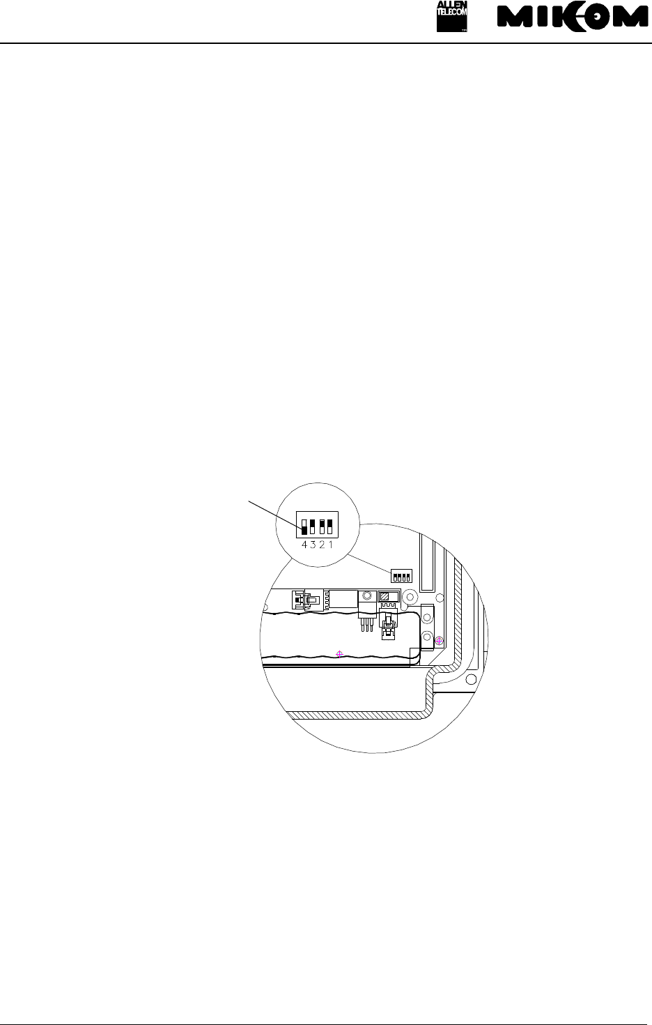
1. Check the position of DIP-Switch 4 ( position OFF ) on the control module.
figure 3-1 Position of DIP-Switch 4
1. Switch on Repeater and PC and connect control cable. Wait until the boot process is
finished.
2. Start Repeater software and login by typing ‘User-ID1’ and ‘P-word1’.
3. Type software command:
Syntax: DNLOAD ↵
4. Exit terminal program immediately.
OFF
ON
DIP-Switch 4
REP1009V1.xx
M0062A0B.doc Id.-No. 148964 Page 811.12.98
5. To start upload procedure type:
Syntax: upload 1 ↵ or
upload 2 ↵
depending on which serial interface is available ( COM 1 or COM 2 ).
6. The copy procedure is running. You will be asked to continue by pressing any key. Now the
software download is in progress. The download lasts approximately 1 minute.
7. Software boot starts automatically.
Response: ‘MIKOM REPEATER MRx01A - SM2009 - SW:REP1009V1.xx’
ENTER <.> <CR> TO LOGIN
3.1.2 Download procedure in local mode, manually controlled:
Required equipment: - PC or Laptop
- one serial RS232 cable: SUB-D9 (female) to SUB-D9 (female)
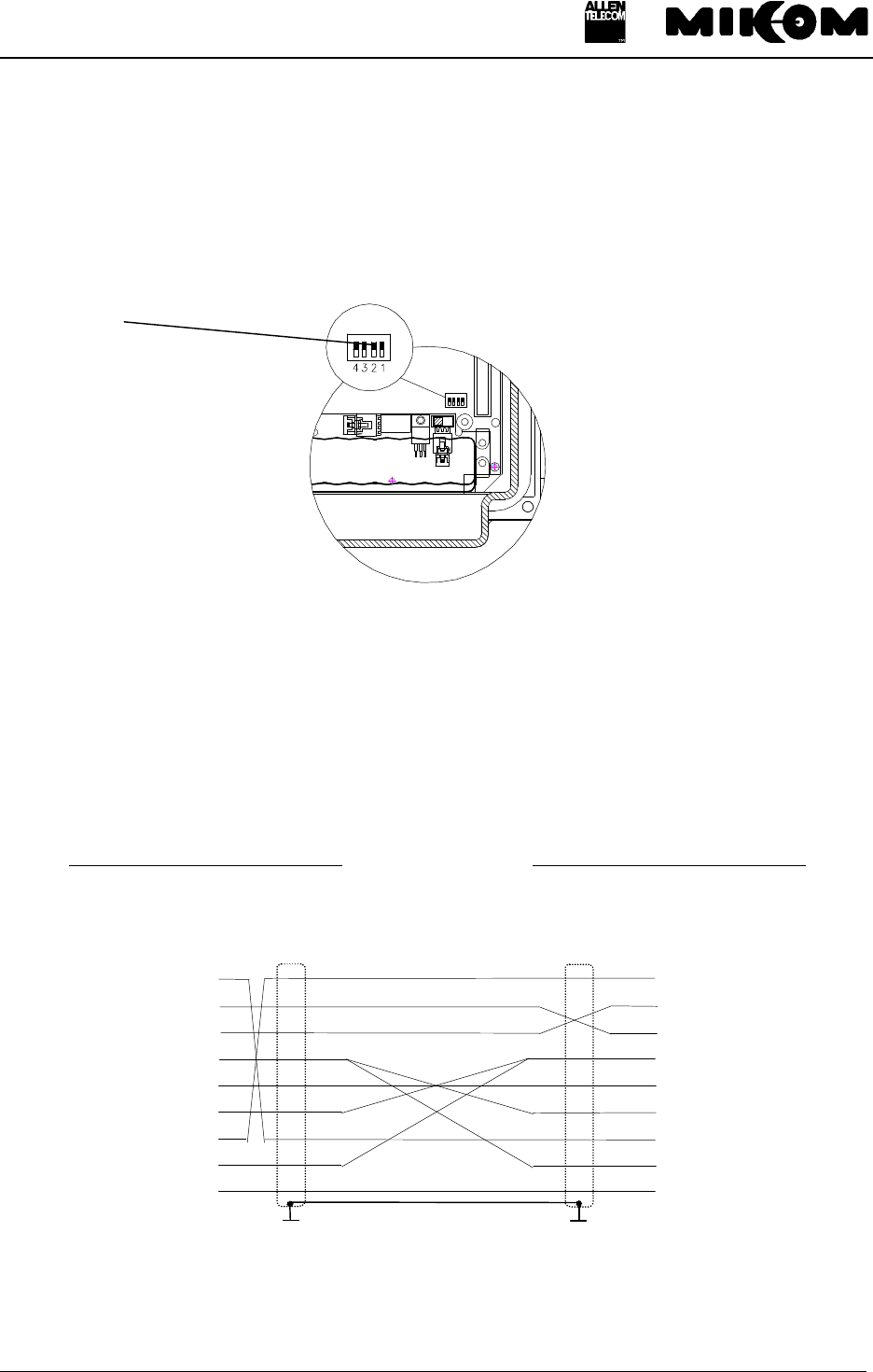
1. Set the DIP-Switch 4 to position ON on the control module.
figure 3-2 Position of DIP-Switch 4
1. To start upload procedure type:
Syntax: upload 1 ↵ or
upload 2 ↵
depending on which serial interface is available ( COM 1 or COM 2 ).
OFF
ON
DIP-Switch 4

REP1009V1.xx
M0062A0B.doc Id.-No. 148964 Page 911.12.98
2. The copy procedure is running. You will be asked to continue by pressing any key. Now the
software download is in progress. The download lasts approximately 5 minutes in local
mode.
3. Software boot starts automatically.
4. Don’t forget to switch back the DIP-Switch 4 to position OFF.
REP1009V1.xx
M0062A0B.doc Id.-No. 148964 Page 10 11.12.98
4 Running the software
4.1 Via PC or Laptop as terminal
The local mode for settings via PC has to be set. Therefore the DIP-Switch 2 has to be at
position OFF.
figure 4-1 DIP-Switch 2 for local mode
F Note: Only if a Modem M1 is used DIP-Switch 2 has to be set.
A VT100 terminal or a PC with VT100 emulation can be connected to the control module
SM2009 by a standard RS232 cable, if necessary in connection with an adapter 9 to 25.
PC or Laptop - Control Module SM2009
9 contact SUB - D- Connector 9 contact SUB - D- Connector
male male
PC RS 232
PIN PIN
1 ) ( 1
2 ) ( 2
3 ) ( 3
4 ) ( 4
5 ) ( 5
6 ) ( 6
7 ) ( 7
8 ) ( 8
9 ) ( 9
figure 4-2 Cable connection
The following communication mode between control module and VT100 is set initially.
OFF
ON

REP1009V1.xx
M0062A0B.doc Id.-No. 148964 Page 11 11.12.98
9600 baud - 8 bit - no parity -1 stopbit
These settings can only be changed after connection of the terminal. If all wanted settings have
been initialized and a modem has to be used it will be recommended to check whether the
settings comply with the capabilities of the modem and the line. Modifications are possible by
software commands.
F Note: Settings on the Repeater can be performed after the following procedure
only.
After connecting the PC to the Repeater, following procedure is necessary to get access to the
program.
MIKOM REPEATER MRx01A - SM2009 - SW: REP1009V1.xx
ENTER <.> <CR>
1. Step: Type the two keys ( . ) FULLSTOP and (↵) ENTER
You have to type the keys:
2. Step: ENTER USER ID
You have to enter: UserID1 ↵
F Note: The input is case sensitive, no blanks. After three mistrial follows
disconnection.
3. Step: ENTER PASSWORD
You have to enter: P-word1 ↵
F Note: The input is case sensitive, no blanks. After three mistrials follows
disconnection.
↵↵
.

REP1009V1.xx
M0062A0B.doc Id.-No. 148964 Page 12 11.12.98
4.2 Via modem
The Repeater will be delivered with a preset init string. This init string was used for internal
tests. In case no connection can be established check the local conditions and change the init
string if necessary.
Three different modem types are available
• PSTN modem ( DigiTel 34P ), line modem
• Siemens M1 for GSM900, wireless modem
• Motorola for GSM900 or GSM1800, wireless modem
The following list contains the description of the AT commands:
&F Sets modem to factory configuration
E0 Echo OFF
S0=1 Auto answer ON; the GSM module / M1 modem goes off-
hook after the first ringing signal.
S7=60 Waiting time for connection after dialing; permissible values
are from 0 ... 60.
B13 Setting to 9600 bps asynchronous mode
\ N6 Auto reliable operation
\ N0 Standard operation, no error correction
+CBST=7,0,1 Set bearer service type to 9600 bps. Non-transparent
connection ( uses RLP )
X3 Not waiting for dial tone; usually used at PABX.
*P1 Switch ON phone
&K4 Enables XON / XOFF flow control
Table 4.2-1 List of AT commands
4.2.1 PSTN modem
A Hayes compatible PSTN modem can be connected to the control module SM 2009 by the
control cable, which is subject of the delivery schedule.
The init string for the PSTN modem is:
AT&F X3 E0 S0=2

REP1009V1.xx
M0062A0B.doc Id.-No. 148964 Page 13 11.12.98
control module SM2009 - cable connection modem
PCMCIA
figure 4-3 Connection of control module and PSTN modem
The following communication mode between control module and VT100 is initially set for the
use of a Hayes-compatible modem.
9600 baud - 8 bit - no parity -1 stopbit
These settings can only be changed after connection of the terminal. If a different modem has
to be used or if the quality of the line does not allow to use the set parameters, the settings
have to be changed in PC mode. This is the same for all other parameters, which can be set
previously for modem mode by software.
F Note: Settings on the Repeater can be performed after the following procedure
only.
After connection to the Repeater following response appears on screen:
1. Step: ENTER USER ID
Response on the screen: ENTER USER ID:------
You have to enter: UserID1 ↵
F Note: The input is case sensitive, no blanks. After three mistrial follows
disconnection.
2. Step: ENTER PASSWORD
Response on the screen: ENTER PASSWORD:--------
You have to enter: P-word1 ↵
F Note: The input is case sensitive, no blanks. After three mistrials follows
disconnection.

REP1009V1.xx
M0062A0B.doc Id.-No. 148964 Page 14 11.12.98
4.2.2 Siemens M1 modem for GSM900
The Siemens M1 modem can be connected to the control module SM 2009 by the control
cable, which is subject of the delivery schedule.
If an individual antenna of a wireless modem is required, the antenna cable may be fed through
a watertight grommet at the connector panel of the housing.
The init string for the Siemens M1 modem is ( without reset circuit )
AT E0 S0=1 B13 S7=60 \N6
The init string for the Siemens M1 modem has to be set by PC / Laptop ( with reset circuit )
AT E0 S0=1 B13 S7=60 \N6 &W
This is the standard init string. If no connection can be established check the local conditions
and change the init string if necessary.
4.2.3 Motorola mobile ( CELLect1 card )
The Motorola mobile ( Dual band ) together with the CELLect1 card can be connected to the
control module SM 2009 by the control cable, which is subject of the delivery schedule.
If an individual antenna of a wireless modem is required, the antenna cable may be fed through
a watertight grommet at the connector panel of the housing.
The init string for the Motorola module is:
AT&F &K4 E0 S0=2 *P1 \N0+CBST=7,0,1

REP1009V1.xx
M0062A0B.doc Id.-No. 148964 Page 15 11.12.98
5 Description of the commands
All available software commands are described in the following chapter.
5.1 Instruction modes
There are four different types of commands:
- SET commands - to change variable parameters
- GET commands - to ask status of variable parameters
- STATUS commands - to ask status of fixed parameters
- ACTION commands - to perform certain actions
5.2 Conventions
The instruction is written in capital letters followed by selections in square brackets to be
entered.
SET NUM [x] [number] ↵↵
The selections can be entered directly following the instruction e.g. SET NUM, but in case
only SET NUM has been entered the computer queries for the missing information in an
interactive dialogue. As an example, x can be substituted by 1 or 2 corresponding to the
wanted position in the telephone list and number can be substituted by the telephone number,
which may consists of up to 25 characters.
↵↵ stands for carriage return. It indicates to press the return key. If, in the above example, the
telephone number 2716 with priority 2 has to be entered the following command has to be
typed:
SET NUM 2 2716 ↵

REP1009V1.xx
M0062A0B.doc Id.-No. 148964 Page 16 11.12.98
5.3 Description of SET commands
SET commands are used to set variable parameters. These parameters are stored non-volatile
in an EEPROM.
Table 5.3-1 presents a summary of SET commands.
Command Description
SET ALARMMASK definition of the severity level for an alarm
SET ALCTHR setting of the ALC threshold
SET ALIAS* alarm message name for external alarms
SET ATT attenuation in DL and UL path
SET BAUD definition of local interface baudrate
SET CF sets the center frequency in UL and DL
SET CFO sets frequency offset in UL and DL
SET DIALMETH changes the dialing method pulse / tone
SET ID Repeater identification
SET ILA sets the maximum value for invalid login attempts
SET INITSTR definition of string for initialisation of the modem
SET LMT changes timeout of local interface
SET LOGIC definition of the logic of I/O ports for external alarms
SET NUM two phone numbers for automatic dial out
SET PAR definition of parity
SET PWD changes password
SET PWRDOWN switch off band/channel modules
SET REP definition of waiting time between alarm calls
SET TIME changes date and time
SET UID changes user identification
* Option Table 5.3-1 Summary of SET commands
If a SET command has been entered not correctly SYNTAX ERROR or VALUE ERROR will
be returned depending on whether the erroneous input was due to an error in correct writing
the command or the erroneous input was a non-plausible value.

REP1009V1.xx
M0062A0B.doc Id.-No. 148964 Page 17 11.12.98
5.3.1 SET ALARMMASK, definition of the severity level for an alarm
Syntax: SET ALARMMASK ↵
Response:ENTER ALARMMASKSTRING: ↵
ENTER BAND MODULE (1-8) : ↵
ENTER PERCEIVED SEVERITY(CRI,MAJ,MIN,WAR,DIS): ↵
where the ALARMMASKSTRING must be one of the following strings
PWR-SUPPLY-MAIN
PWR-SUPPLY-8V
PWR-SUPPLY-12V
LITHIUM-BATT
PASSWORD
TEMPERATURE
DOOR
SYNTH-LOCK-UL
SYNTH-LOCK-DL
ALC-UL
ALC-DL
CURRENT-AT-8V
CURRENT-AT-12V
or if the corresponding option is active
ACCU-VOLTAGE-L1
ACCU-VOLTAGE-L2
VSWR
EXT-ALARM-1
EXT-ALARM-2
EXT-ALARM-3
EXT-ALARM-4
For each alarmmask string it is also possible to set the severity level for all modules at the same
time.
Syntax:
SET ALARMMASK-ALL ALC-UL CRI CRI CRI CRI CRI CRI CRI CRI
With this command it is possible to change the severity level for an alarm message. The
severity level for an optional alarm can only be changed if the option is enabled. There will be
no alarm message if the severity level has been set to DIS ( disabled ), or if the corresponding
band/channel module has been switched off with the command SET PWRDOWN ENA.

REP1009V1.xx
M0062A0B.doc Id.-No. 148964 Page 18 11.12.98
The severity parameter defines five levels for an alarm message and can be set in the alarm
mask. The severity levels indicate how the capability of the managed object has been affected.
The levels are described below and are ordered from most severe to least severe:
- Critical: The critical severity level indicates that a service affecting condition has
occurred and an immediate corrective action is required to restore the capability
of the managed object.
- Major: The major severity level indicates that a service affecting condition has
developed and an urgent corrective action is required. Such a severity can be
reported, for example, when there is a severe degradation in the capability of the
managed object and its full capability must be restored.
- Minor: The minor severity level indicates the existence of a non-service affecting fault
condition and that corrective actions should be taken in order to prevent a more
serious failure. Such a severity can be reported, for example, when the detected
alarm condition is not currently degrading the capability of the managed object.
- Warning: The warning severity level indicates the detection of a potential or impending
service affecting failure before any significant effect has been caused. Action
should be taken to further diagnose and correction of the problem shall prevent
a more serious service affecting failure.
- Disable: The disable severity level indicates that the detected failure has no influence
on the system and shall not be sent to the terminal.
The alarm message for all status alarms will not be sent, if the alarm mask is set to DIS or the
module is deactivated with PWRDOWN ENA.
5.3.2 SET ALCTHR, setting of the ALC threshold
With this command it is possible to set the ALC threshold. The value for the ALC threshold
will be determined in factory and can be found on a label on the RF modules. In case a second
module will be mounted or a module will be exchanged the values for the ALC threshold have
to be compared. If the modules have different values, the higher value must be set, due to the
fact that the threshold can only be set for the whole Repeater.
F Note: The higher ALC threshold value has to be set.
Syntax: SET ALCTHR ↵
Response: BAND-MODULE ( 1/2 3/4 5/6 7/8 ): ↵

REP1009V1.xx
M0062A0B.doc Id.-No. 148964 Page 19 11.12.98
ENTER MODE (UL or DL) : ↵
ENTER ALC THRESHOLD 0 - 255 : ↵
* * * C A U T I O N * * *
THE FOLLOWING ACTION MAY CAUSE DAMAGE TO
EXTERNAL HARDWARE
PRESS <Y> + <CR> TO PERFORM CHANGE
Allowed values are binary digits 0 ... 255. Default value is 255.
5.3.3 SET ALIAS*, enter name strings for external alarms 1 ... 4
Syntax:SET ALIAS ↵
Response: ENTER ENTRY - 1 TRU 4: ↵
ENTER ALARM ACTIVE NAME STRING -MAX 30 CHARS
: ↵
ENTER ALARM NON ACTIVE NAME STRING -MAX 30 CHARS
: ↵
You will be asked to enter a name string for the external alarms 1 ... 4. Two different names
can be defined, the first input is the name for the alarm active name and the second input is the
name if the alarm is not active. Be aware the OMC needs appropriate key words for
recognising an alarm.
5.3.4 SET ATT, sets attenuation in uplink or downlink path
Syntax : SET ATT ↵
Response: ENTER BAND MODULE ( 1-8 ): ↵
ENTER MODE ( UL or DL): ↵
ENTER ATTENUATION: ↵
You will be asked to enter the band module, mode and attenuation ( attenuation in dB, only
values between 0 and 30 dB in steps of 2 dB ).
5.3.5 SET BAUD, definition of baudrate used
Syntax: SET BAUD [ baudrate ] ↵
Response: ENTER BAUDRATE – 1200, 2400, 4800 OR 9600:

REP1009V1.xx
M0062A0B.doc Id.-No. 148964 Page 20 11.12.98
After first power on or change of battery a baudrate of 9600 is used.
5.3.6 SET CF, setting of the center frequency
Syntax: SET CF ↵
Response: ENTER BAND MODULE (1-8): ↵
ENTER CF UL <MHz>: ↵
ENTER CF DL <MHz>: ↵
The frequency can be set within the range of the GSM900 / GSM1800 band.
5.3.7 SET CFO, setting of the frequency offset
Syntax: SET CFO ↵
Response: ENTER BAND MODULE (1-8): ↵
ENTER CFO UL <kHz>: ↵
ENTER CFO DL <kHz>: ↵
The frequency offset can be set in the range of +/- 1 MHz in steps of 10 kHz.
5.3.8 SET DIALMETH, setting of the dialing method
Syntax: SET DIALMETH ↵
Response: ENTER DIALING METHOD: T - TONE DIALING
P - PULSE DIALING
ENTER CHOICE: ↵
The default method is tone dialing.
5.3.9 SET ID, Repeater identification
Syntax: SET ID ↵
Response: ENTER ID STRING - MAX 25 CHARS: ↵

REP1009V1.xx
M0062A0B.doc Id.-No. 148964 Page 21 11.12.98
where Repeater ID may be max. 25 symbols. All characters between 21 H and 7E H will be
accepted.
If you skip this request, the default Repeater identification appears:
Response: Repeater ID: MIKOM
5.3.10 SET ILA, definition of a limit for invalid login attempts
Syntax: SET ILA ↵
Response: ENTER VALUE : ↵
The maximum allowed number of invalid login attempts have to be entered. Default value is 8.
Setting range is 3 – 10 invalid login attempts.
5.3.11 SET INITSTR, definition of a initialisation string
Syntax : SET INITSTR [Initstring] ↵
Response: ENTER MODEM INIT STRING - MAX 60 CHARS
: ↵
where : [ Initstring ] is max. 60 symbols, 21 H to
7E H is allowed.
Initstring stands for the string stored in the modem for initialisation. It is defined in the manual
of the modem.
This stored INIT STRING was used for internal tests. In case no connection can be established
check the local conditions and change the INIT STRING if necessary
F Note: Use upper case characters for entry.
5.3.12 SET LMT, to change timeout for local maintenance interface
Syntax: SET LMT ↵
Response: ENTER VALUE: ↵

REP1009V1.xx
M0062A0B.doc Id.-No. 148964 Page 22 11.12.98
Enter the local maintenance terminal timeout in minutes. LMT can be set in the range from 5 to
99 minutes. Default value is 25 minutes.
5.3.13 SET LOGIC, definition of the I/O port logic for the external alarms
With this command it is possible to set the logic of the I/O ports for the external alarms. The
logic can be changed for each alarm separately. The default settings of the I/O ports on the
control module are LLHH. This command is only available if the option “External Alarms” is
active.
Syntax: SET LOGIC↵
Response: ENTER ALARM LEVEL 1 (H/L): ↵
ENTER ALARM LEVEL 2 (H/L): ↵
ENTER ALARM LEVEL 3 (H/L): ↵
ENTER ALARM LEVEL 4 (H/L): ↵
5.3.14 SET NUM, definition of 2 phone numbers used for the automatic dial out
Syntax: SET NUM ↵
Response: ENTER ENTRY - 1 TRU 2: ↵
ENTER PHONE NUMBER - MAX 25 CHARS: ↵
Depending on the entry the numbers can have the priority 1 or 2 and max. 25 symbols are
allowed.
5.3.15 SET PAR, definition of parity
Syntax : SET PAR [ parameter ] ↵
Response: SELECT PARAMETER:
7 BITS ODD PARITY - 1
7 BITS EVEN PARITY - 2
8 BITS NO PARITY - 3
enter choice :
After first power on or change of battery the interface module is preset to 8 Bits no parity.
5.3.16 SET PWD, to change password
Syntax: SET PWD ↵
Response: ENTER ENTRY - 1 TRU 4: ↵

REP1009V1.xx
M0062A0B.doc Id.-No. 148964 Page 23 11.12.98
1 to 4 different passwords are possible. Users with password 1 or 2 have full access to the
Repeater ( SET and GET commands possible). Users with password 3 or 4 have restricted
access ( only GET commands are available ).
After typing this command you are requested to type the old password and finish with ↵.
ENTER OLD PASSWORD: ----- ↵
If the old password was correct you are requested to type the new password ( 1 - 10 symbols
long - letters, numbers, case sensitive ) and finish with ↵.
ENTER NEW PASSWORD – MIN 1 MAX 10 CHARS: --------- ↵
To store the new password the new password has to be typed again.
ENTER NEW PASSWORD AGAIN TO CONFIRM : ---------- ↵
PASSWORD HAS BEEN CHANGED
After first power on or change of batteries the default password ( to be determined for each
customer ) is used.
5.3.17 SET PWRDOWN, to switch off band/channel modules
Syntax: SET PWRDOWN ↵
Response: ENTER BAND MODULE ( 1-8 ): ↵
SET POWER DOWN MODE: E - ENABLE POWER DOWN
D - DISABLE POWER DOWN
ENTER CHOICE: ↵
After typing the command you are asked to enter band module and the mode.
Power down enable, means to switch off the band module.
5.3.18 SET REP, definition of waiting time between alarm call trials
If an alarm call is not acknowledged, the call will be repeated in time intervals, until it is
acknowledged. The minimum value for the waiting time is 5 minutes.
Syntax : SET REP [ cycle length ] ↵
Response: ENTER CYCLE LENGTH IN MIN: ↵
REP CYCLE: 10 MIN

REP1009V1.xx
M0062A0B.doc Id.-No. 148964 Page 24 11.12.98
where : [ cycle length ] is the waiting time in minutes
5 - 99 is allowed ( default: 10 min )
5.3.19 SET TIME, to change actual time and date
Syntax: SET TIME ↵
After carriage return the software queries line by line for the input as follows:
ENTER YEAR < YYYY > (SKIP WITH CR):
ENTER MONTH < MM > (SKIP WITH CR):
ENTER DAY < DD > (SKIP WITH CR):
ENTER HOURS < HH > (SKIP WITH CR):
ENTER MINUTES < MM > (SKIP WITH CR):
PRESS CR TO START
5.3.20 SET UID, changes user identification
Syntax: SET UID ↵
Response: ENTER ENTRY - 1 TRU 4: ↵
1 to 4 user identification terms are possible. Users with user ID 1 or 2 have full access to the
Repeater ( SET and GET commands possible). Users with ID 3 or 4 have restricted access
( only GET commands are available ).
After typing this command you are requested to type the old UID and finish with ↵.
ENTER OLD USER ID: ----- ↵
If the old UID was correct you are requested to type the new UID and finish with ↵.
ENTER NEW USER ID - MIN 1 MAX 10 CHARS:: --------- ↵
To store the new UID type it again.
ENTER NEW USER ID AGAIN TO CONFIRM : ---------- ↵
USER ID HAS BEEN CHANGED
After first power on or changing of the Lithium battery the default password ( to be
determined for each customer ) will be loaded.

REP1009V1.xx
M0062A0B.doc Id.-No. 148964 Page 25 11.12.98
5.4 Description of the GET commands
GET commands are used to ask for the status of variable parameters.
Table 5.4-1 presents a summary of GET commands.
Command Description
GET ALARMMASK definition of the severity level for an alarm
GET ALCTHR setting of the ALC threshold
GET ALIAS* displays all name strings of external alarms
GET ATT attenuation in DL and UL path
GET BAUD baudrate of the local interface
GET CF lists center frequencies of 8 band modules
GET CFO frequency offset
GET DIALMETH information about dial method pulse / tone
GET ID Repeater identification
GET ILA sets the maximum value for invalid login attempts
GET INITSTR initialisation string for the modem
GET LMT timeout of the local interface
GET LOGIC definition of the logic of I/O ports for external alarms
GET NUM two phone numbers for automatic dial out
GET PAR parity ( communication parameter of the local interface )
GET PWRDOWN displays state if a band module is powered down
GET REP waiting time between alarm calls via modem
GET TIME date and time of system
* Option
Table 5.4-1 Summary of GET commands
If a GET command has been entered not correctly, SYNTAX ERROR will be returned.
By typing the GET command all status information are given. Due to the fact that the report is
very long the GET report can be split in two parts. You have to type GET1 to see the first part
and GET2 to see the second part.
In the following an example of a GET1 and a GET2 report is given.
REP1009V1.xx
M0062A0B.doc Id.-No. 148964 Page 26 11.12.98
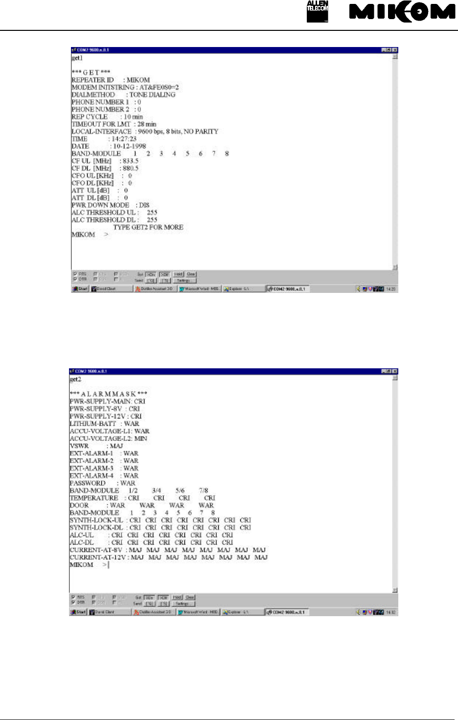
figure 5-1 Example of a GET1 report
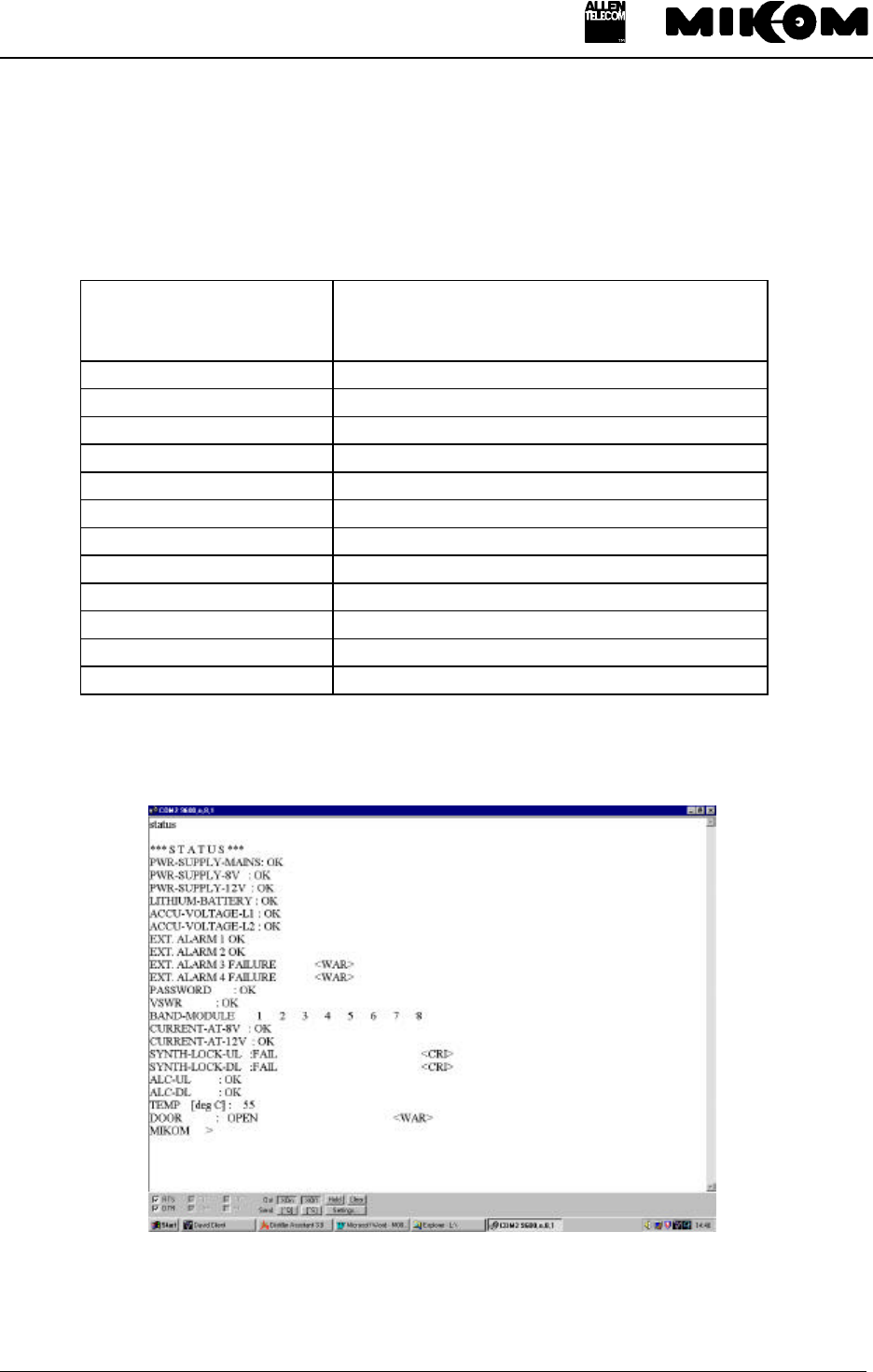
figure 5-2 Example of a GET2 report

REP1009V1.xx
M0062A0B.doc Id.-No. 148964 Page 27 11.12.98
5.4.1 GET ALARMMASK, displays the set severity level for an alarm
Syntax: GET ALARMMASK ↵
Response:
*** A L A R M M A S K ***
PWR-SUPPLY-MAIN: CRI
PWR-SUPPLY-8V : CRI
PWR-SUPPLY-12V : CRI
LITHIUM-BATT : WAR
ACCU-VOLTAGE-L1*: WAR
ACCU-VOLTAGE-L2*: MIN
VSWR* : MAJ
EXT-ALARM-1* : WAR
EXT-ALARM-2* : WAR
EXT-ALARM-3* : WAR
EXT-ALARM-4* : WAR
PASSWORD : WAR
BAND-MODULE 1/2 3/4 5/6 7/8
TEMPERATURE : CRI CRI CRI CRI
DOOR : WAR WAR WAR WAR
BAND-MODULE 1 2 3 4 5 6 7 8
SYNTH-LOCK-UL : CRI CRI CRI CRI CRI CRI CRI CRI
SYNTH-LOCK-DL : CRI CRI CRI CRI CRI CRI CRI CRI
ALC-UL : CRI CRI CRI CRI CRI CRI CRI CRI
ALC-DL : CRI CRI CRI CRI CRI CRI CRI CRI
CURRENT-AT-8V : MAJ MAJ MAJ MAJ MAJ MAJ MAJ MAJ
CURRENT-AT-12V : MAJ MAJ MAJ MAJ MAJ MAJ MAJ MAJ
* Optional
The alarmmask string will only be displayed if the corresponding option is implemented.
Depending on the system configuration the response might be different compared to the
example above.
5.4.2 GET ALCTHR, displays the set value for the ALC threshold
Syntax: GET ALCTHR ↵
Response: BAND-MODULE 1/2 3/4 5/6 7/8
ALC THRESHOLD UL : 170
ALC THRESHOLD DL : 200
5.4.3 GET ALIAS*, name strings for external alarms
Syntax: GET ALIAS ↵

REP1009V1.xx
M0062A0B.doc Id.-No. 148964 Page 28 11.12.98
Response: NAME STRINGS FOR ALARMS
EXT. ALARM 1 ACTIVE – EXT. ALARM 1 FAILURE
EXT. ALARM 1 NON ACTIVE – EXT. ALARM 1 OK
EXT. ALARM 2 ACTIVE – EXT. ALARM 2 FAILURE
EXT. ALARM 2 NON ACTIVE – EXT. ALARM 2 OK
EXT. ALARM 3 ACTIVE – EXT. ALARM 3 FAILURE
EXT. ALARM 3 NON ACTIVE – EXT. ALARM 3 OK
EXT. ALARM 4 ACTIVE – EXT. ALARM 4 FAILURE
EXT. ALARM 4 NON ACTIVE – EXT. ALARM 4 OK
or UPS ALARM ACTIVE
UPS NON ACTIVE
BATTERY VOLTAGE LOW
BATTERY VOLTAGE OK
UPS DOOR OPEN
UPS DOOR CLOSED
BATTERY DOOR OPEN
BATTERY DOOR CLOSED
5.4.4 GET ATT, gain setting
Syntax: GET ATT ↵
Response:
BAND-MODULE 1 2 3 4 5 6 7 8
CF UL [MHz] 833.5
CF DL [MHz] 947.5
CFO UL [kHz] 0
CFO DL [kHz] 0
ATT UL [dB] 0
ATT DL [dB] 4
5.4.5 GET BAUD, baudrate
Syntax: GET BAUD ↵
Response: LOCAL - INTERFACE : 9600 bps, 8 bits, NO PARITY
( also 4800, 2400 or 1200 are possible)
5.4.6 GET CF, set centre frequency in the GSM900 / GSM1800 band
Syntax: GET CF ↵
Response, e.g. for the GSM900 system:

REP1009V1.xx
M0062A0B.doc Id.-No. 148964 Page 29 11.12.98
BAND MODULE 1 2 3 4 5 6 7 8
CF UL [MHz] 833.5 0
CF DL [MHz] 880.5 0
CFO UL [kHz] 0 0
CFO DL [kHz] 0 0
ATT UL [dB] 0 0
ATT DL [dB] 4 0
5.4.7 GET CFO, frequency offset
Syntax: GET CFO ↵
Response, e.g. for the GSM900 system:
BAND MODULE 1 2 3 4 5 6 7 8
CF UL [MHz] 833.5 0
CF DL [MHz] 880.5 0
CFO UL [kHz] 0 0
CFO DL [kHz] 0 0
ATT UL [dB] 0 0
ATT DL [dB] 4 0
5.4.8 GET ID, Repeater identification
Syntax: GET ID ↵
Response: REPEATER ID: MIKOM
5.4.9 GET ILA, displays stored number of invalid login attempts
Syntax: GET ILA ↵
Response: ILA Invalid login attempts:
5.4.10 GET INITSTR, displays the string which is used to initialize the modem
Syntax: GET INITSTR ↵
Response: If a Hayes compatible modem is used:
MODEM INITSTRING: AT&F &K4 E0 S0=2

REP1009V1.xx
M0062A0B.doc Id.-No. 148964 Page 30 11.12.98
5.4.11 GET LMT, timeout for local interface
Syntax: GET LMT ↵
Response: TIMEOUT FOR LMT : 25 min
5.4.12 GET LOGIC, displays the logic of the I/O ports
Syntax: GET LOGIC ↵
Response: EXT. ALARM LEVEL: L L H H
5.4.13 GET NUM, displays stored phone numbers
Syntax : GET NUM [ x ] ↵
where: [ x ] is priority in the list, may be 1 or 2
or
Syntax: GET NUM ↵
Response: PHONE NUMBER 1: 0000
PHONE NUMBER 2: 0000
5.4.14 GET PAR, modem parity
Syntax: GET PAR ↵
Response: LOCAL-INTERFACE : 9600 bps, 8 bits, NO PARITY
5.4.15 GET PWRDOWN, displays power down status of the modules
Syntax: GET PWRDOWN ↵
Response: BAND-MODULE 1 2 3 4 5 6 7 8
PWR DOWN MODE: ENA DIS
This command displays the status of the band modules.

REP1009V1.xx
M0062A0B.doc Id.-No. 148964 Page 31 11.12.98
If a module is switched off the response is ‘POWER DOWN MODE ENA’.
If a module is switched on the response is ‘POWER DOWN MODE DIS’.
5.4.16 GET REP, defines waiting time between trials for automatic alarm call
Syntax: GET REP ↵
Response: REP CYCLE : 10 min
( Possible range is 5....99 min )
5.4.17 GET TIME, to get the actual time and date
Syntax: GET TIME ↵
Response: TIME : 13:30:20
DATE : 02-12-98
REP1009V1.xx
M0062A0B.doc Id.-No. 148964 Page 32 11.12.98
5.5 Status commands
Status commands are used to receive information about fixed parameters.
Table 5.5-1 presents a summary of STATUS commands.
Command Description
STATUS ACCU* see chapter 5.6.1
STATUS ALC ALC in DL and UL for each band module
STATUS AMPBIAS current consumption of the RF modules
STATUS DOOR door open/ closed
STATUS EXTALARM * see chapter 5.6.2
STATUS HIST history of alarms
STATUS I2C status of the I²C bus
STATUS LBATT Lithium battery
STATUS PWR power supply
STATUS SYNTH modules in operation / not in operation
STATUS TEMP actual temperature inside Repeater cabinet
STATUS VSWR * see chapter 5.6.3
* Option Table 5.5-1 Summary of STATUS commands
By typing STATUS commands all status information are given.
figure 5-3 Example of a STATUS report

REP1009V1.xx
M0062A0B.doc Id.-No. 148964 Page 33 11.12.98
5.5.1 STATUS ALC, displays the actual status
Syntax: STATUS ALC ↵
Response: BAND-MODULE 1 2 3 4 5 6 7 8
ALC-UL : OK OK
ALC-DL : OK ALARM < CRI >
If the Repeater exceeds the set ALC threshold an alarm will be released. The value for the
ALC threshold is written on a label on the conversion module. The alarm may have one of the
severity levels.
5.5.2 STATUS AMPBIAS, current consumption of the RF modules
Syntax: STATUS AMPBIAS ↵
Response: BAND-MODULE 1 2 3 4 5 6 7 8
CURRENT-AT-8V :OK OK
CURRENT-AT-12V:OK ALARM < CRI >
Displays the status of the current consumption in the conversion modules. In case of a defect
conversion module, the values might be too low or too high, which results in an alarm
message. The alarm can have on of the severity levels
5.5.3 STATUS DOOR, door open / closed
Syntax: STATUS DOOR ↵
Response : BAND MODULE 1/2 3/4 5/6 7/8
DOOR : OPEN < WAR >
A DOOR OPEN condition results in an alarm message. The alarm may have one of the five
severity levels.
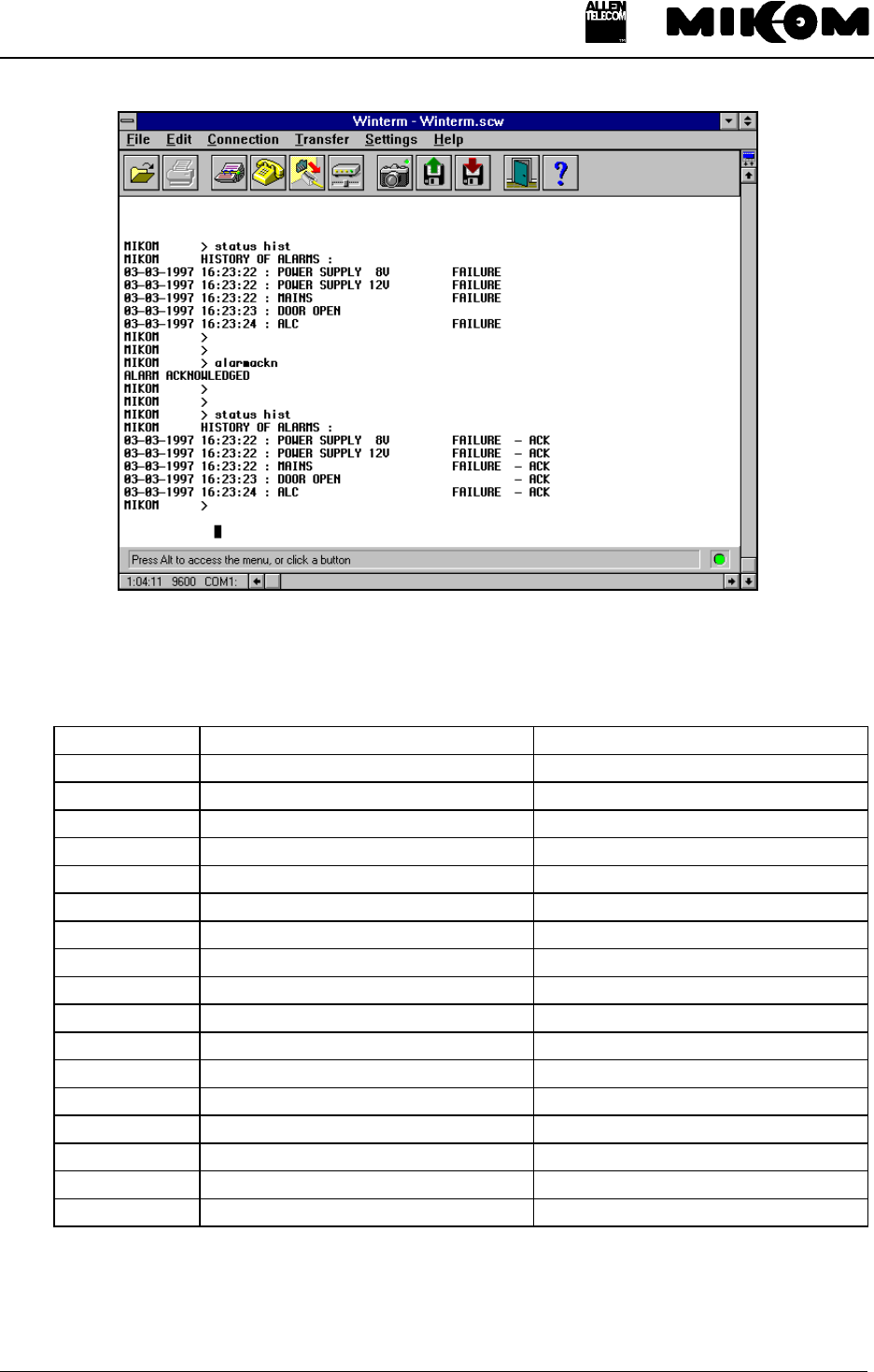
5.5.4 STATUS HIST, list of all occurred alarms
Syntax: STATUS HIST ↵
Response: HISTORY OF ALARMS:
NO ALARMS STORED
In the following example there is also a status hist listing depicted, after the alarms have been
acknowledged.
REP1009V1.xx
M0062A0B.doc Id.-No. 148964 Page 34 11.12.98
figure 5-4 Example of a STATUS HIST report
The following table contains a list of all available alarm:
NO. ALARM NAME ALARM ACTIVE STATUS
1AMPLIFIER BIAS FAILURE
2POWER SUPPLY 8 V FAILURE
3POWER SUPPLY 12 V FAILURE
4POWER SUPPLY MAINS FAILURE
5SYNTH FAILURE
6DOOR OPEN
7VSWR** ALARM
8ALC FAILURE
9ACCU VOLTAGE** LOW
10 LITHIUM BATTERY VOLTAGE LOW
11 OVERTEMP FAILURE
12 INVALID LOGIN ATTEMPT
13 I2C BUS FAILURE
14* EXT. ALARM 1** FAILURE
15* EXT. ALARM 2** FAILURE
16* EXT. ALARM 3** FAILURE
17* EXT. ALARM 4** FAILURE
*Alarms default settings, changeable by software instruction SET ALIAS
** Only available if the option is active

REP1009V1.xx
M0062A0B.doc Id.-No. 148964 Page 35 11.12.98
5.5.5 STATUS I2C , displays the status of the I²C bus
Syntax: STATUS I2C ↵
Response: I2C BUS OK
or I2C BUS FAILURE < WAR >
This alarm may have one of the possible severity levels. A defect ribbon cable between the
control module and the modules might be the cause for an I²C bus failure or if a Repeater was
disconnected from mains.
5.5.6 STATUS LBATT, response information about Lithium battery
Syntax: STATUS LBATT ↵
Response: LITHIUM BATTERY OK
or LITHIUM BATTERY VOLTAGE TOO LOW
If the voltage of the Lithium battery is < 1 V, an alarm will be released.
5.5.7 STATUS PWR, status of the power supplies
Syntax : STATUS PWR ↵
Response: PWR-SUPPLY-8V : OK
PWR-SUPPLY-12V : OK
PWR-SUPPLY-MAINS : OK
In case of power supply 12 Volts failure.
Response: PWR-SUPPLY-12V : FAILURE < WAR >
If power is available the message is OK, if no power can be detected a failure will be displayed.
5.5.8 STATUS SYNTH, modules in operation
Syntax : STATUS SYNTH ↵

REP1009V1.xx
M0062A0B.doc Id.-No. 148964 Page 36 11.12.98
Response: BAND-MODULE 1 2 3 4 5 6 7 8
SYNTH-LOCK-UL: OK OK
SYNTH-LOCK-DL: OK FAIL < CRI >
A defect synthesizer indicates that the conversion module has to be exchanged.
5.5.9 STATUS TEMP, temperature
Syntax: STATUS TEMP ↵
Response: BAND-MODULE 1/2 3/4 5/6 7/8
TEMP [deg C] : 56
In case 4 Repeaters are installed, the temperature will be displayed for each unit with a
resolution of 1° C. The accuracy is ± 2° C.
An alarm will be released at a temperature ≥ +75° C
The response then is: TEMPERATURE = 76 °C, Temperature Alarm - Stage 1
Another alarm will be released at a temperature ≥ +90° C.
The response then is: TEMPERATURE = 91 °C, Temperature Alarm - Stage 2
RF stages are in POWER DOWN mode as long as the temperature alarm stage 2 exists and
will be switched on again if the temperature is below +85° C.

REP1009V1.xx
M0062A0B.doc Id.-No. 148964 Page 37 11.12.98
5.6 Optional status commands
In case of implementing optional modules like external alarms, battery backup module or
VSWR following commands are available.
5.6.1 STATUS ACCU, response voltage value of backup battery
Syntax: STATUS ACCU ↵
Response: ACCU-VOLTAGE-L1 : OK
ACCU-VOLTAGE-L2 : OK
If the voltage of the backup battery is < 7.7 V, a warning will be released ( L1 ).
If the voltage of the backup battery is < 7.0 V, an alarm will be released ( L2 ).
5.6.2 STATUS EXTALARM, status of external alarms
Syntax: STATUS EXTALARM ↵
Response: EXT. ALARM 1 OK
EXT. ALARM 2 OK
EXT. ALARM 3 FAILURE < WAR >
EXT. ALARM 4 FAILURE < WAR >
5.6.3 STATUS VSWR, displays the DL antenna VSWR
Syntax: STATUS VSWR ↵
Response: VSWR : OK
The VSWR module measures the voltage standing wave ratio of the DL output antenna port.
If the VSWR falls below approximately 10 dB an alarm is released.
This enables the provider to know the status of the cable to the antenna. If a cable is defective
the VSWR will decrease and the alarm will be released. The alarm can be forwarded to an
OMC, so that faults and irregularities can be recognised and eliminated rather quick.
The alarm has one of the severity levels ( DISable, WARning, MINor, MAJor, CRItical ).

REP1009V1.xx
M0062A0B.doc Id.-No. 148964 Page 38 11.12.98
5.7 Action commands
Action commands are used to perform a certain kind of action without an additional parameter.
Table 5.7-1 presents a summary of action commands.
Command Description
ACCUDIS * starts to discharge the accumulator, see chapter 5.8.1
ALARMACKN acknowledgement of all occurred alarms
BYE disconnect Repeater from telephone line in remote mode
BYE disconnect Repeater from local maintenance interface
DNLOAD starts software download
STOPDIS * stops to discharge the accumulator, see chapter 5.8.2
VER revision number of software
* Options Table 5.7-1 Summary of action commands
5.7.1 ALARMACKN, acknowledgement of all alarms.
Syntax: ALARMACKN ↵
Response: ALARM ACKNOWLEDGED
Entered alarms in the alarm list can be acknowledged by simply ringing back a dn typing
ALARMACKN.
Acknowledged alarms will be indicated in the STATUS HIST with ‘-ack’. As soon as the
alarms have been acknowledged the alarm relay will be reset and the summary LEDs switch to
green light again. Additionally connected devices for alarm indication will be switched off with
this command. All data of the STATUS HIST are lost if the Repeater will be booted or if the
Repeater was disconnected from mains.
A new failure will be written immediately in the STATUS HIST.
5.7.2 BYE, disconnect Repeater from telephone line in remote mode
Syntax: BYE ↵
5.7.3 BYE, disconnect Repeater from local maintenance interface
Syntax: BYE ↵

REP1009V1.xx
M0062A0B.doc Id.-No. 148964 Page 39 11.12.98
Response: LOGOUT FROM LOCAL MAINTENANCE INTERFACE
5.7.4 DNLOAD, starts software download
Syntax: DNLOAD ↵
It is not possible to interrupt this process after typing the command DNLOAD. If there is no
input for about 1 minute the Repeater boots automatically.
A separate documentation is available for the remote download procedure.
Exit terminal program immediately.
To start upload procedure type:
Syntax: upload1.bat or
upload2.bat
depending on which serial interface is available ( COM 1 or COM 2 ).
5.7.5 VER, displays the version of software and hardware
Syntax : VER ↵
Response: HW MRx01A – SM2009 SW REP1009 V1.xx
*actual version number
Displays the hardware configuration ( control module SM2009 ) and the integrated software
version.

REP1009V1.xx
M0062A0B.doc Id.-No. 148964 Page 40 11.12.98
5.8 Optional action commands
5.8.1 ACCUDIS, starts discharge of accumulator
Syntax: ACCUDIS ↵
Response: START DISCHARGE OF BACKUP BATTERY
Starts to discharge the backup battery and stops automatically if the minimum voltage is
reached.
5.8.2 STOPDIS, stops battery discharging immediately
Syntax: STOPDIS ↵
Response: BATTERY DISCHARGE STOPPED
Stops the discharge of the backup battery immediately.

REP1009V1.xx
M0062A0B.doc Id.-No. 148964 Page 41 11.12.98
5.9 Error messages
There are two error messages resulting from erroneous inputs and one error message that
results from hardware failure.
5.9.1 SYNTAX ERROR
This error message will be returned if a command is written not correctly or if the written
command does not exist. The computer is ready for new inputs immediately.
5.9.2 VALUE ERROR
This error message will be returned if a non-plausible value has been entered. Possibly, the
value was out of the defined range, as e.g. in case of a negative number, or it was not in the
defined range of the character set as e.g. 19H in INIT STR.
5.9.3 I²C-BUS ERROR
This error occurs if a part of the hardware has been damaged, e.g. the control module cannot
get access to a synthesizer, because of a bad ribbon cable or an I²C-Bus slave ties the one line
of the bus to ground.
5.10 Features
1. By pressing the arrow keys ↑ or ↓, the last ten commands, stored in the command buffer
will be repeated forward and backward.
2. To correct a typing error use backspace function as usual.
3. After typing a command of an option which is not active, the response is “OPTION NOT
ACTIVE”.

REP1009V1.xx
M0062A0B.doc Id.-No. 148964 Page 42 11.12.98
6 Index
A
Action commands
ALARMACKN 39
BYE 39
DNLOAD 40
VER 40
AT commands 12
C
Commands
GET 26
SET 16
STATUS 33
Communication
locally 5
remotely 6
E
Error message 42
Errors
I²C-Bus 42
Syntax error 42
Value error 42
G
Gain
Settings via modem 12
GET commands
GET ALARMMASK 28
GET ALCTHR 28
GET ALIAS* 29
GET ATT 29
GET BAUD 29
GET CF 30
GET CFO 30
GET ID 30
GET ILA 30
GET INITSTR 31
GET LMT 31
GET LOGIC 31
GET NUM 31
GET PAR 31
GET PWRDOWN 32
GET REP 32
GET TIME 32
I
Init string
for Motorola modem 14
for PSTN modem 12
for Siemens M1 modem 14
used in factory 12
Installation 6
L
Login procedure
in modem mode 13
M
Modem 11
Modem types 12
Motorola (Flare) 14
PSTN 12
Siemens M1 14
O
Optional action commands
ACCUDIS 41
STOPDIS 41
R
Repeating commands 42
Running the software
via Laptop/PC 10
via modem 12
S
SET commands
SET ALARMMASK 17
SET ALCTHR 19
SET ALIAS 19
SET ATT 19
SET BAUD 20
SET CF 20
SET CFO 20
SET DIALMETH 20
SET ID 21
SET ILA 21
SET INITSTR 21
SET LMT 22
SET LOGIC 22
SET NUM 22
SET PAR 22
SET PWD 23
SET PWRDOWN 23
SET REP 24

REP1009V1.xx
M0062A0B.doc Id.-No. 148964 Page 43 11.12.98
SET TIME 24
SET UID 24
Severity levels 18
Software download 7
local mode 7
STATUS commands
STATUS ALC 34
STATUS AMPBIAS 34
STATUS DOOR 34
STATUS HIST 34
STATUS I2C 36
STATUS LBATT 36
STATUS PWR 36
STATUS SYNTH 37
STATUS TEMP 37
STATUS commands, optional
STATUS ACCU 38
STATUS EXTALARM 38
STATUS VSWR 38