Andrew Wireless Innovations Group RPT-MR801BI MR801BI Power and MR801BI SMR Band Repeater User Manual M0079A1A
Andrew Wireless Innovations Group MR801BI Power and MR801BI SMR Band Repeater M0079A1A
Contents
- 1. Users manual
- 2. Users manual update
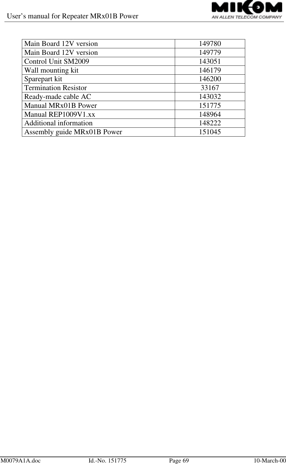
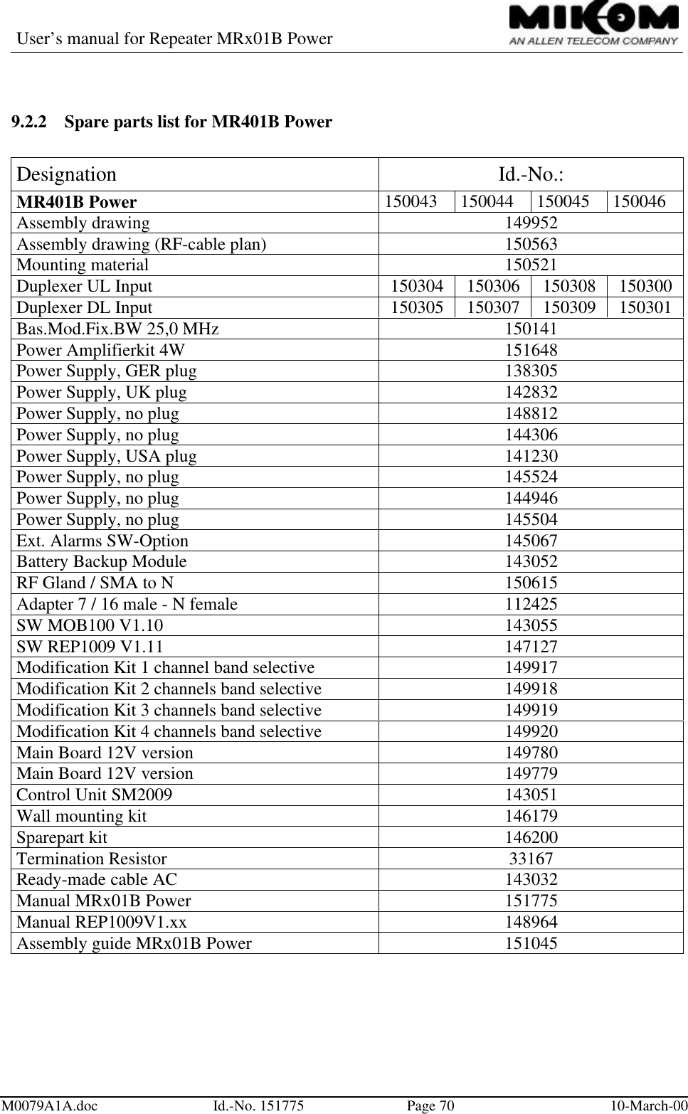
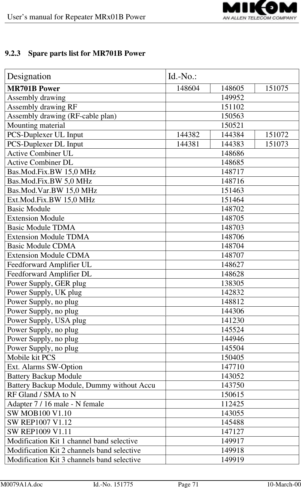
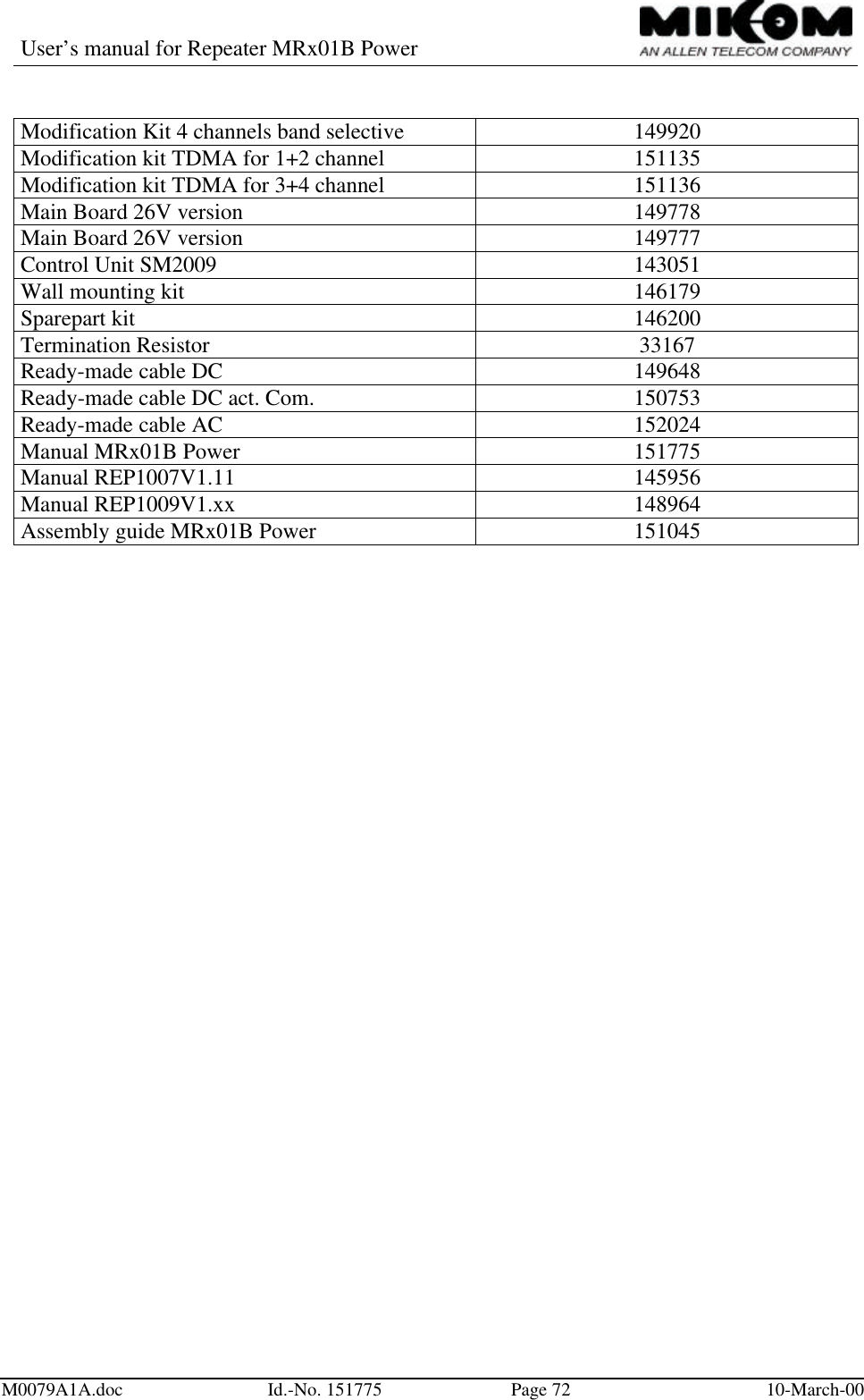
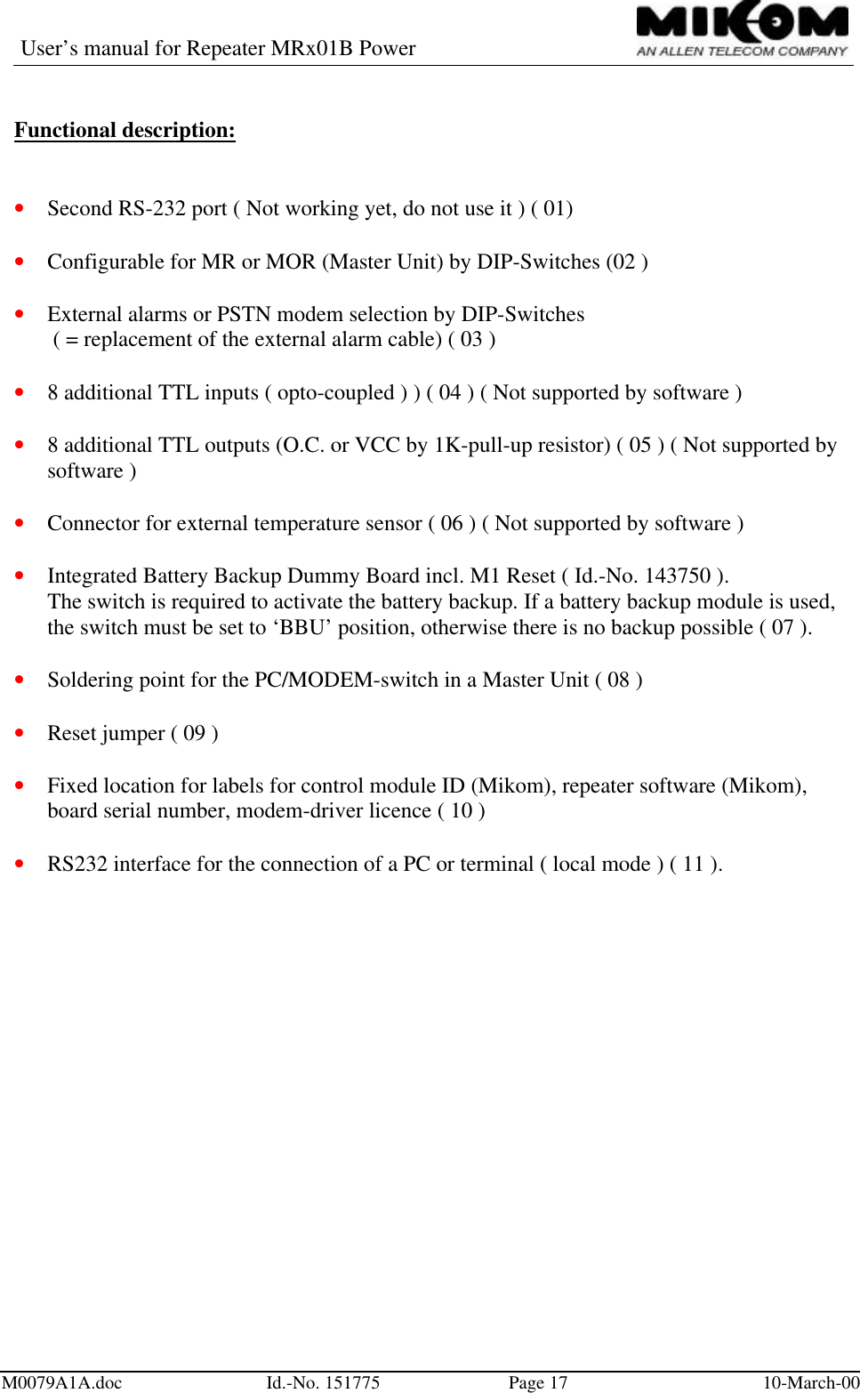
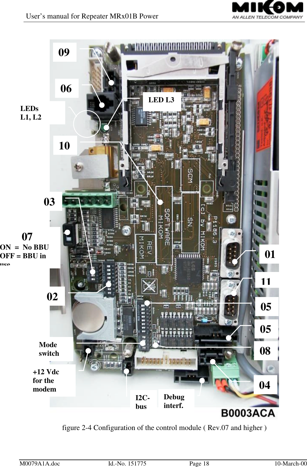
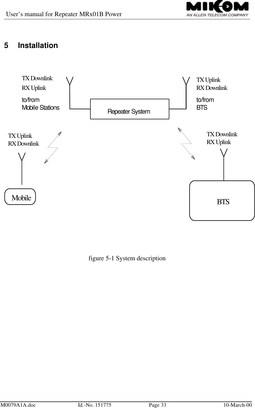
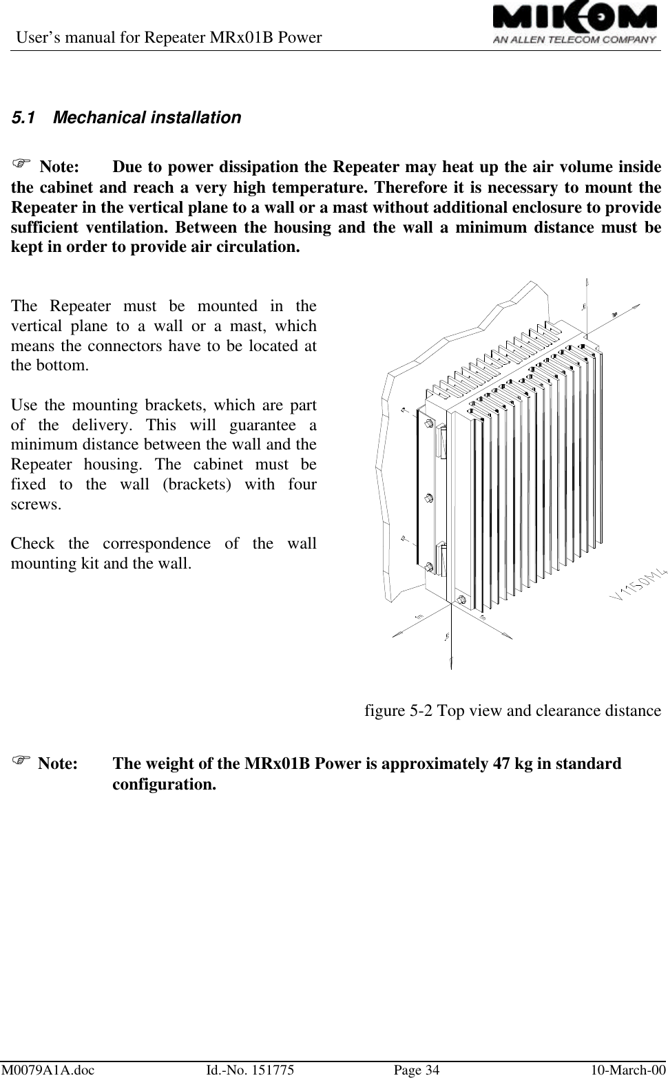
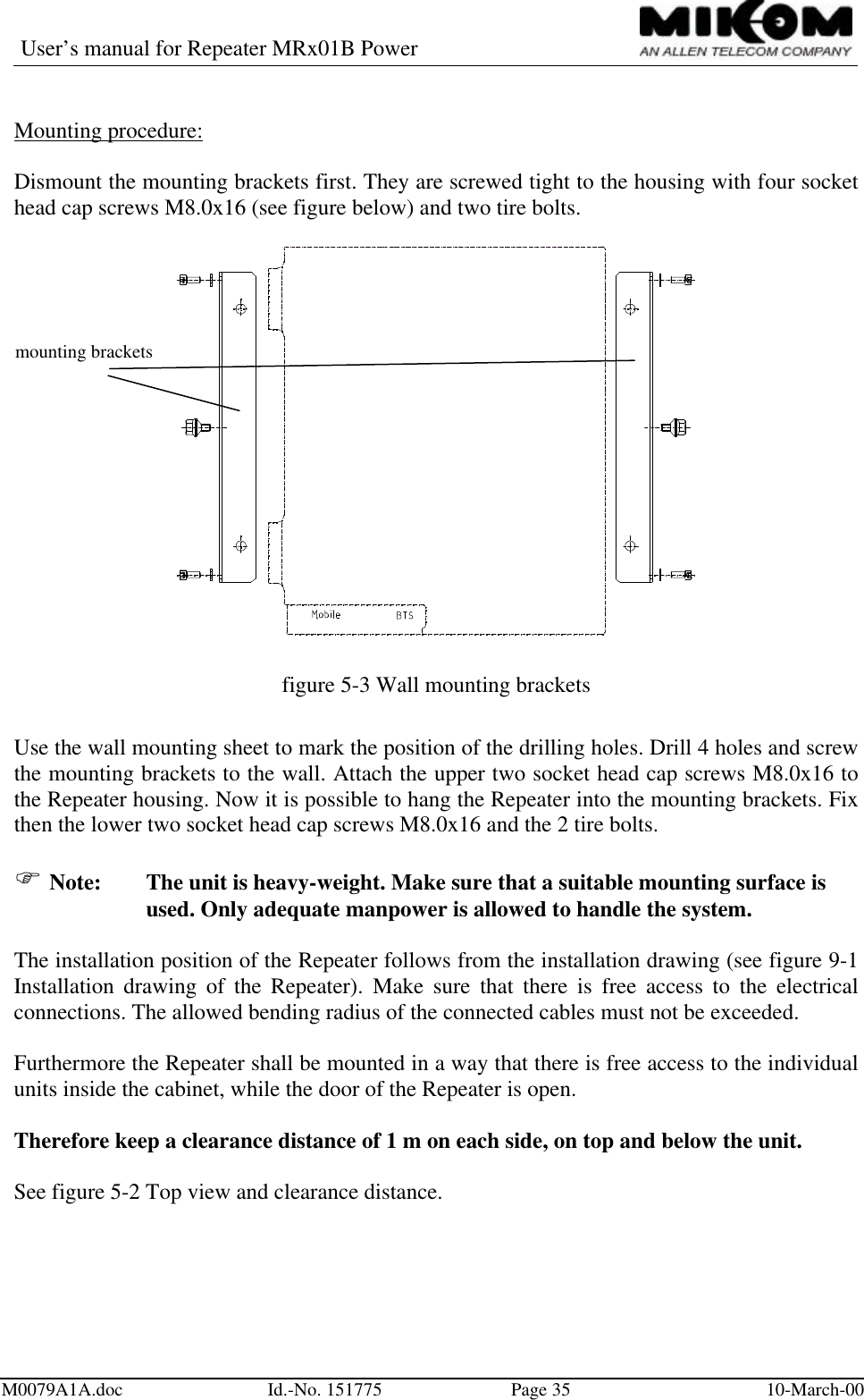
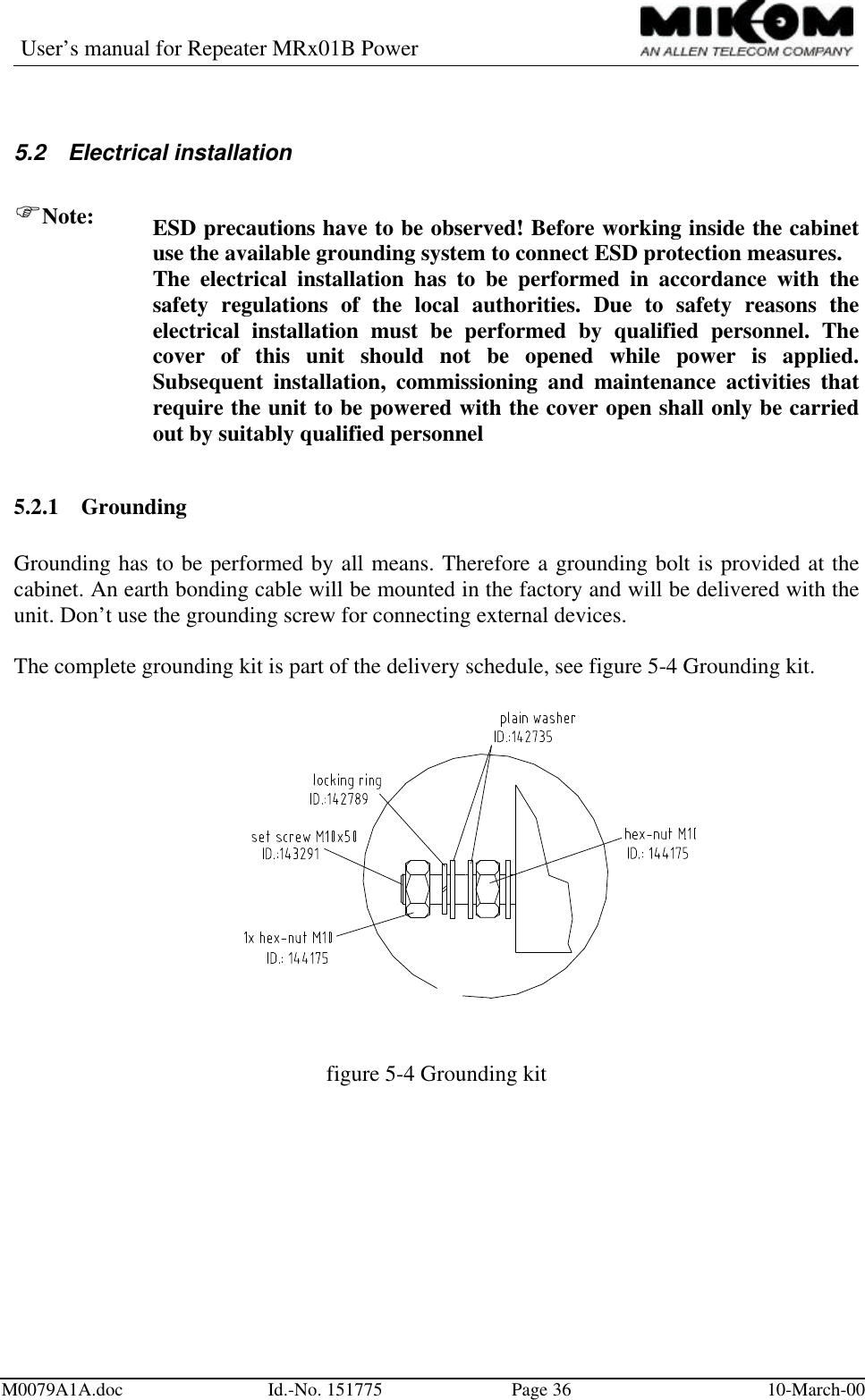
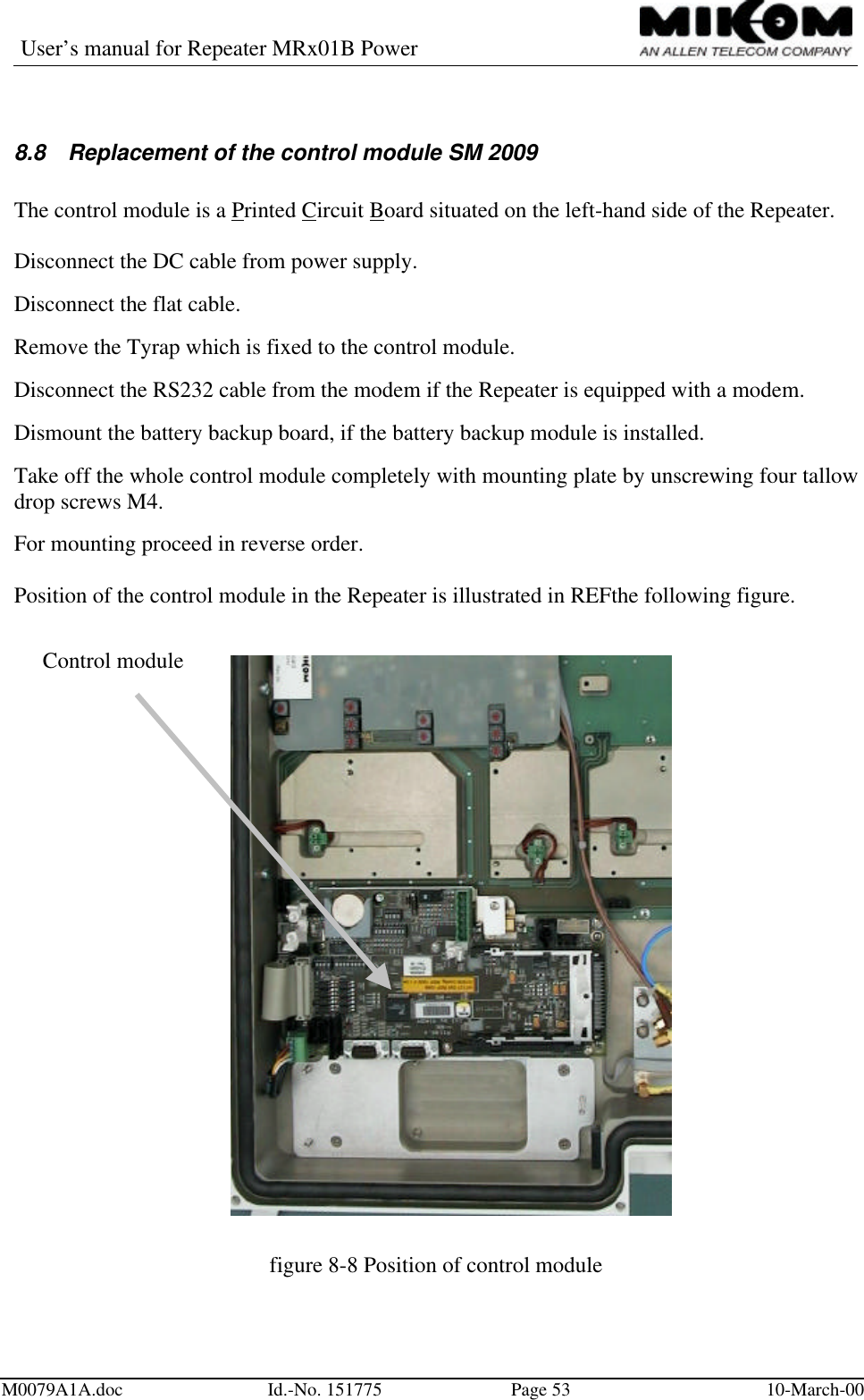
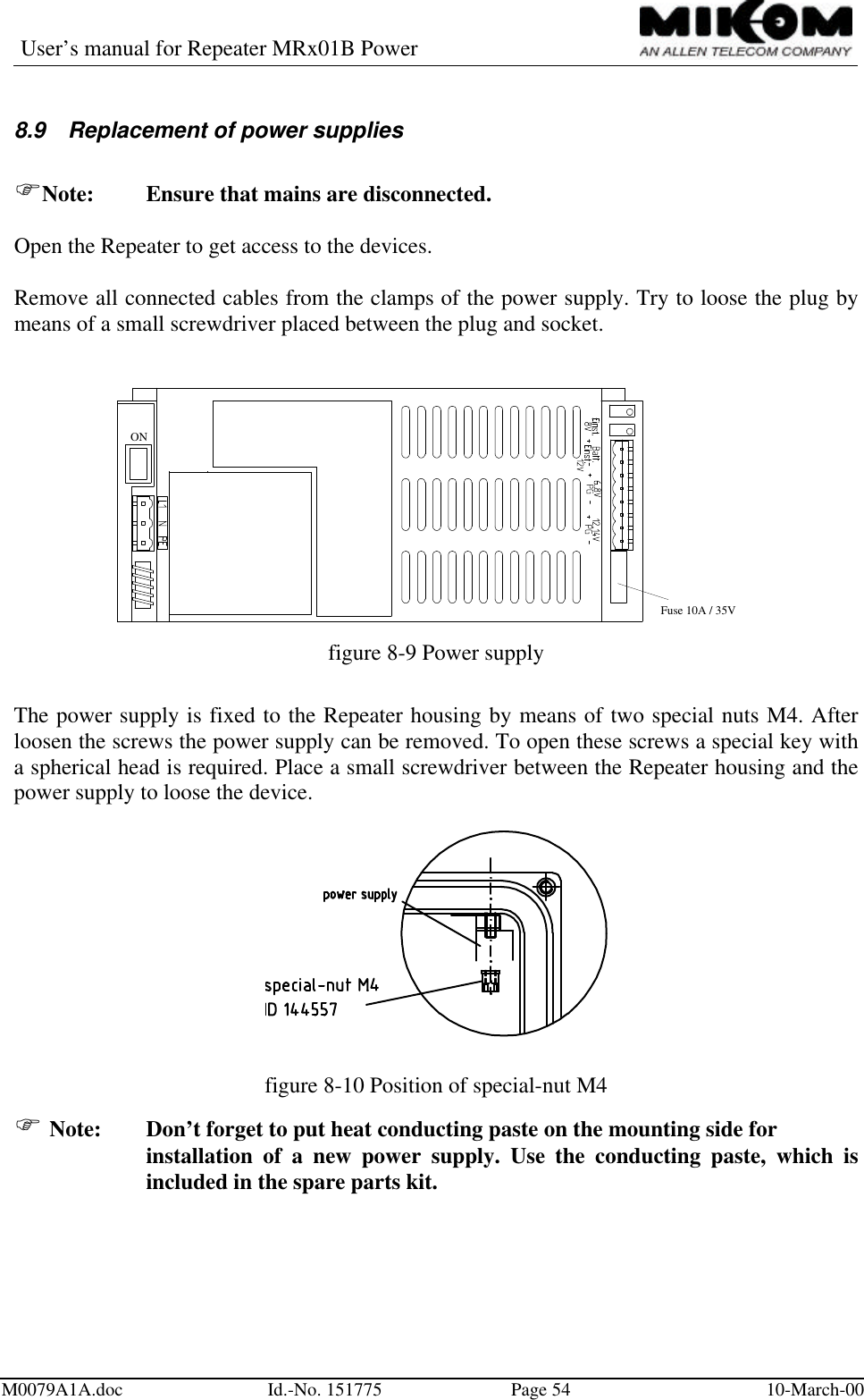
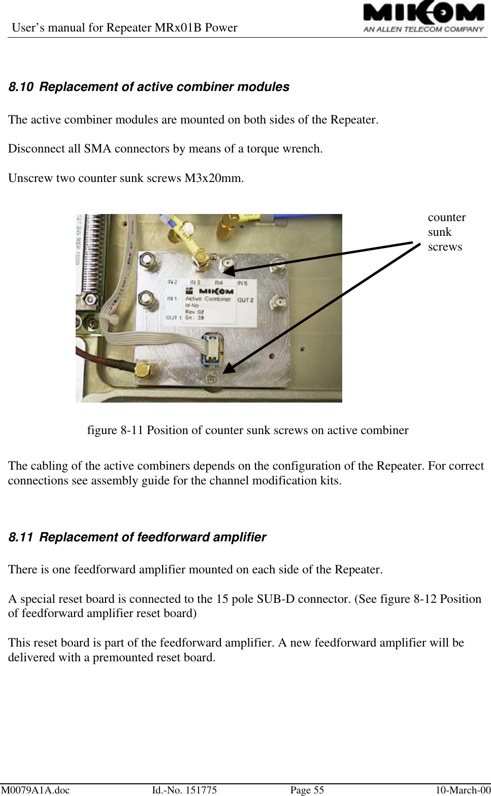
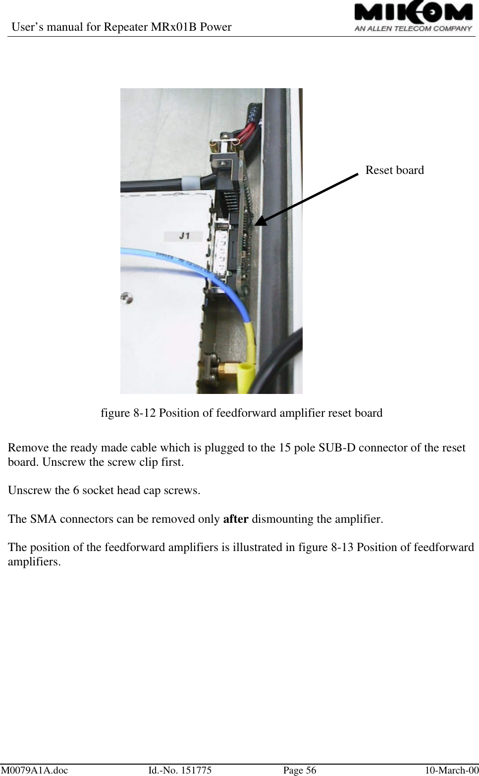
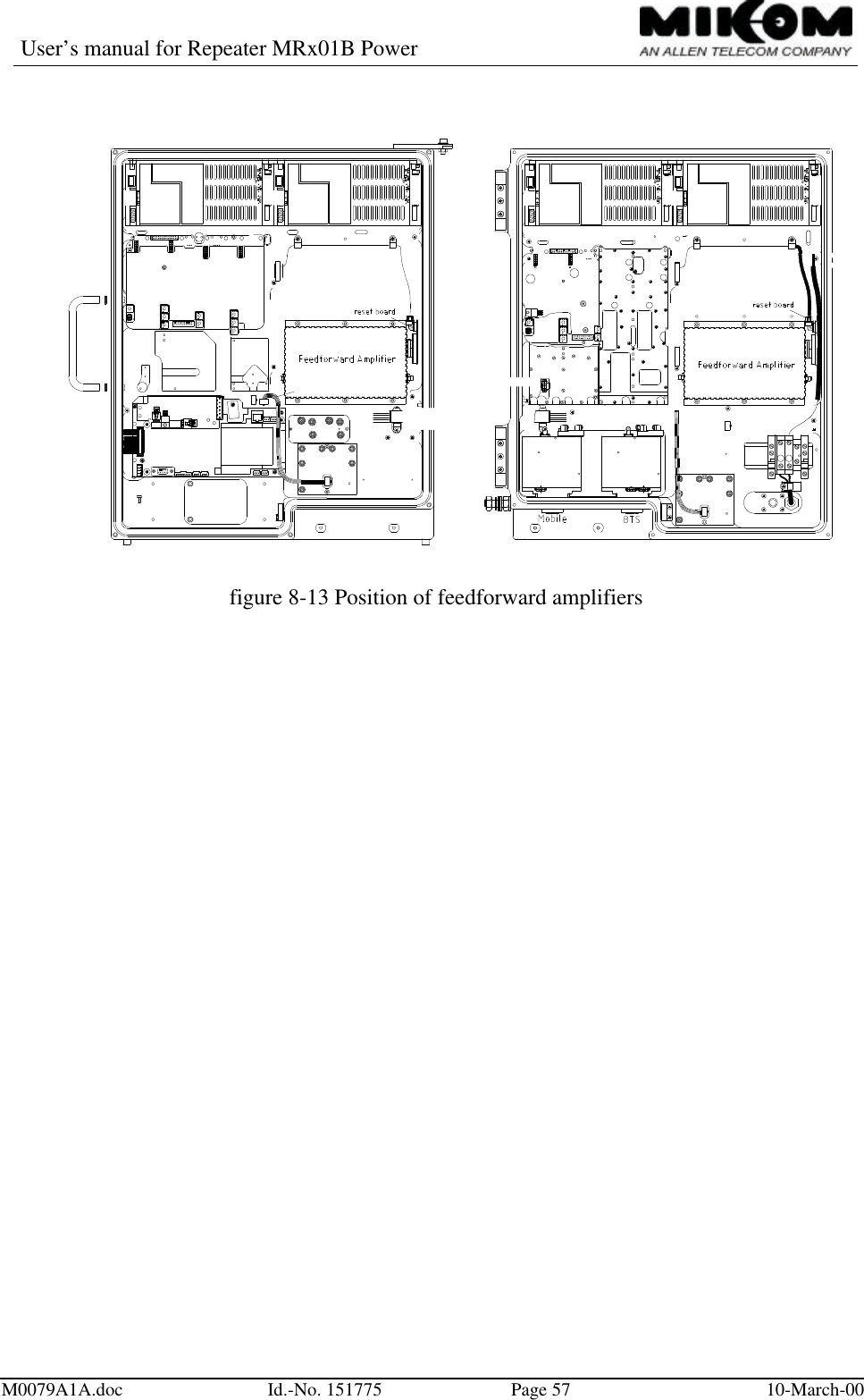
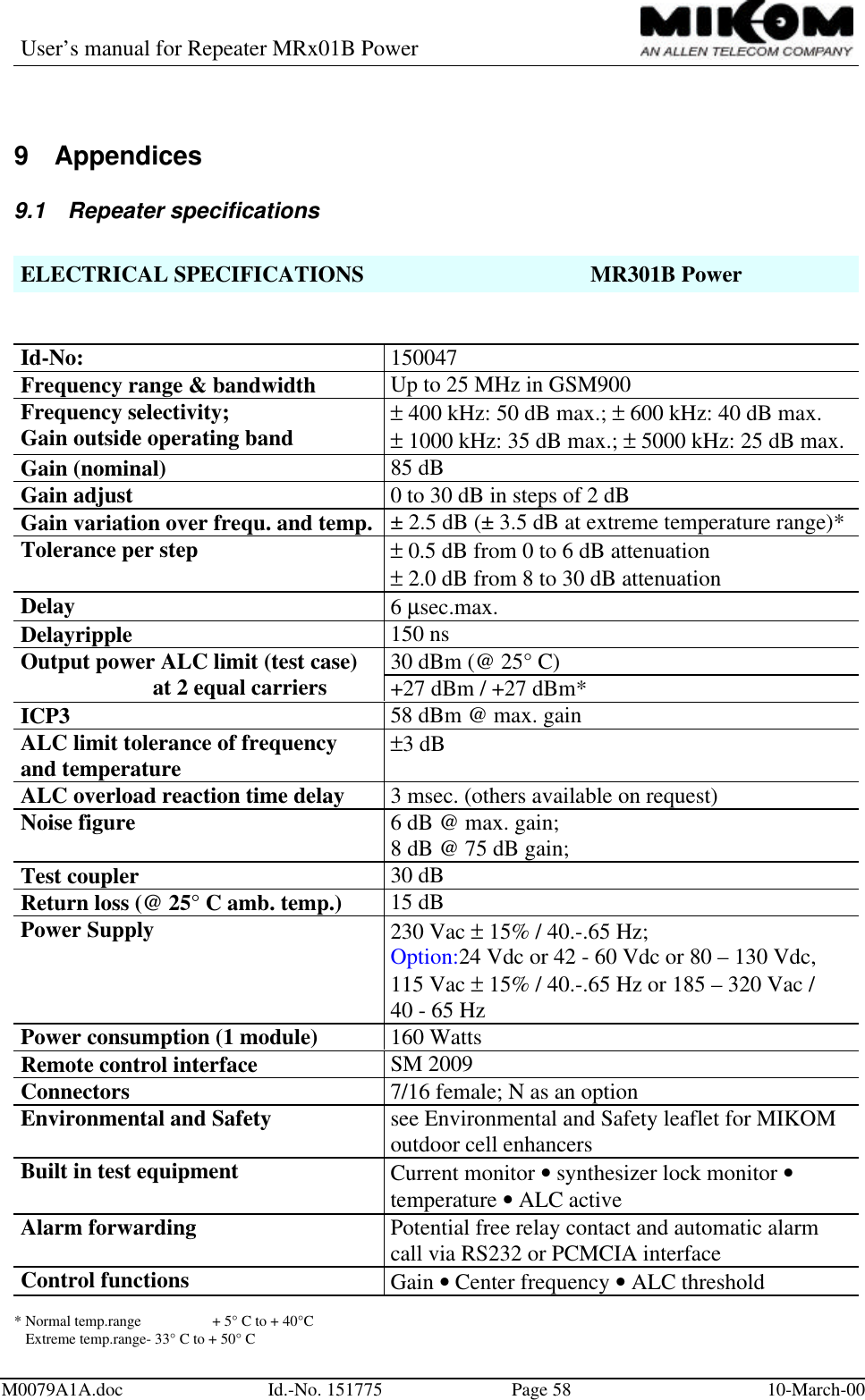
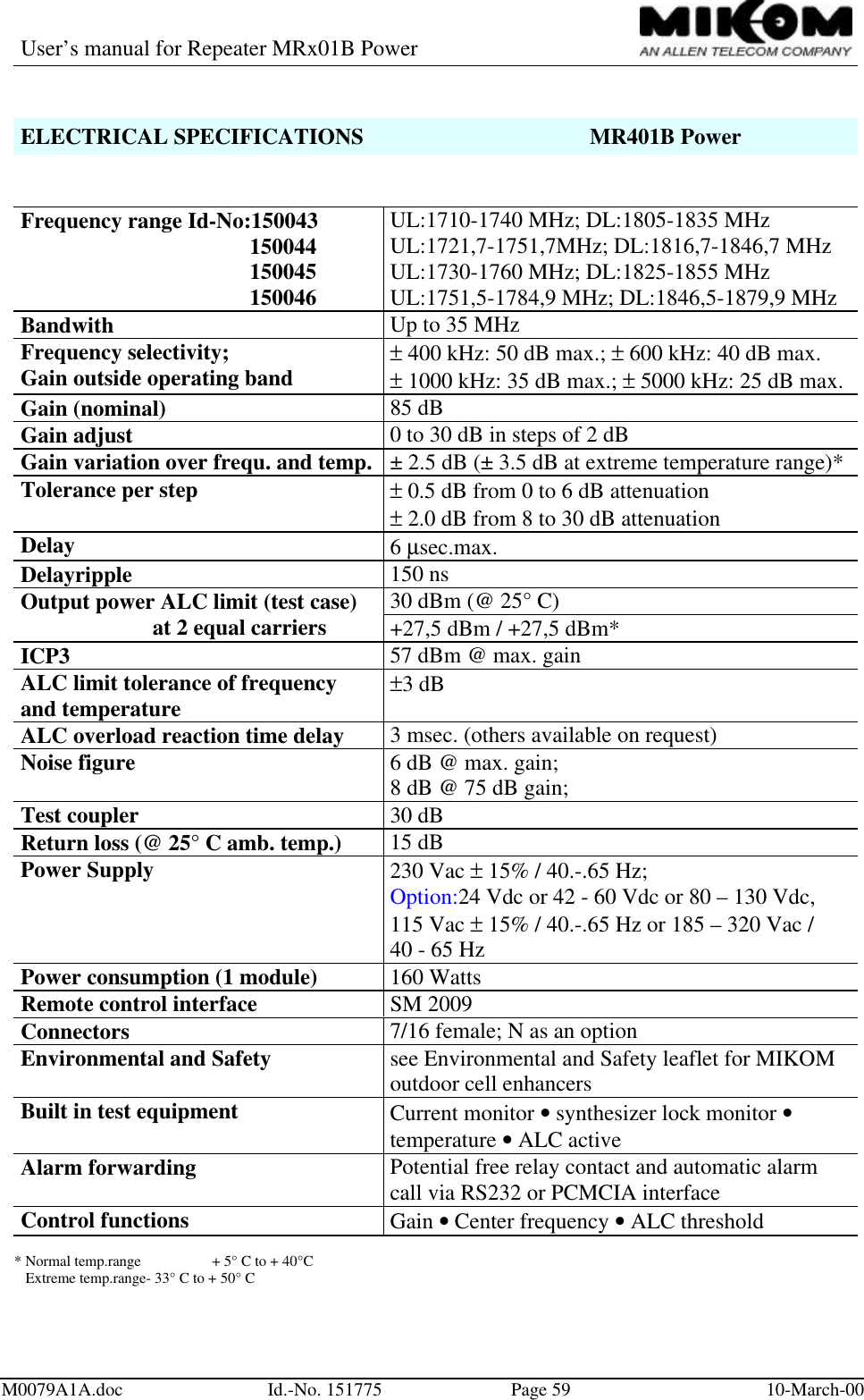
Users manual

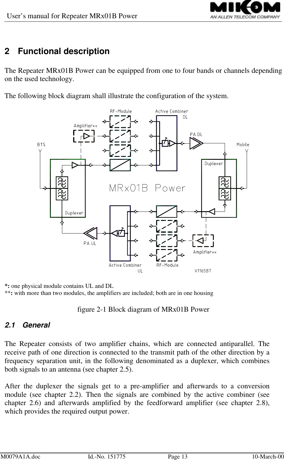
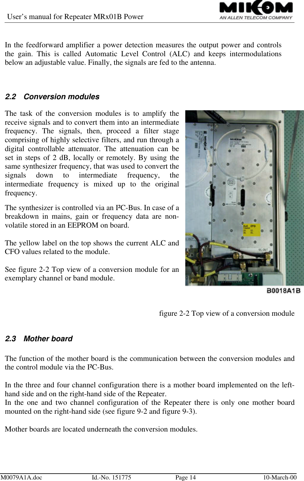
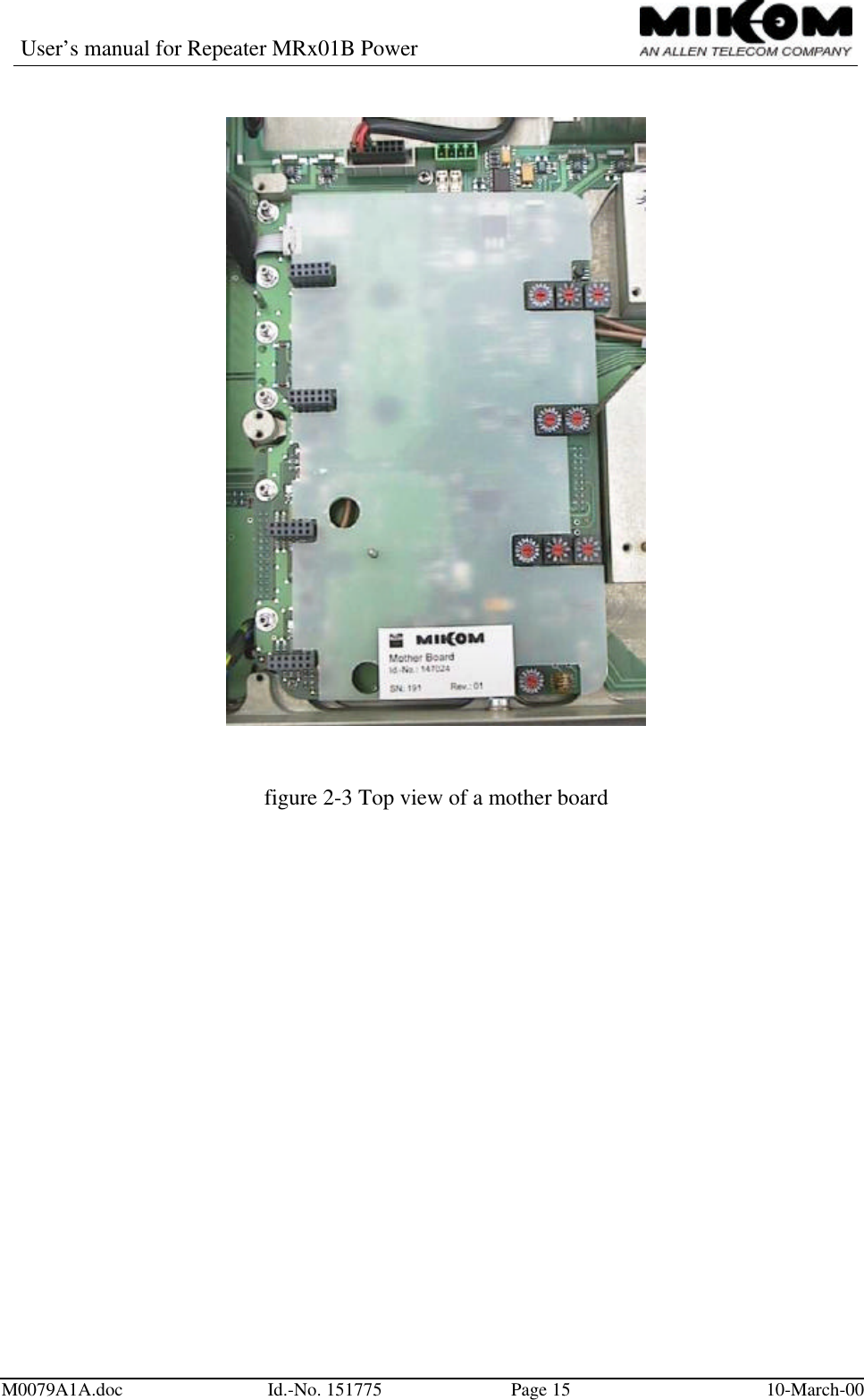
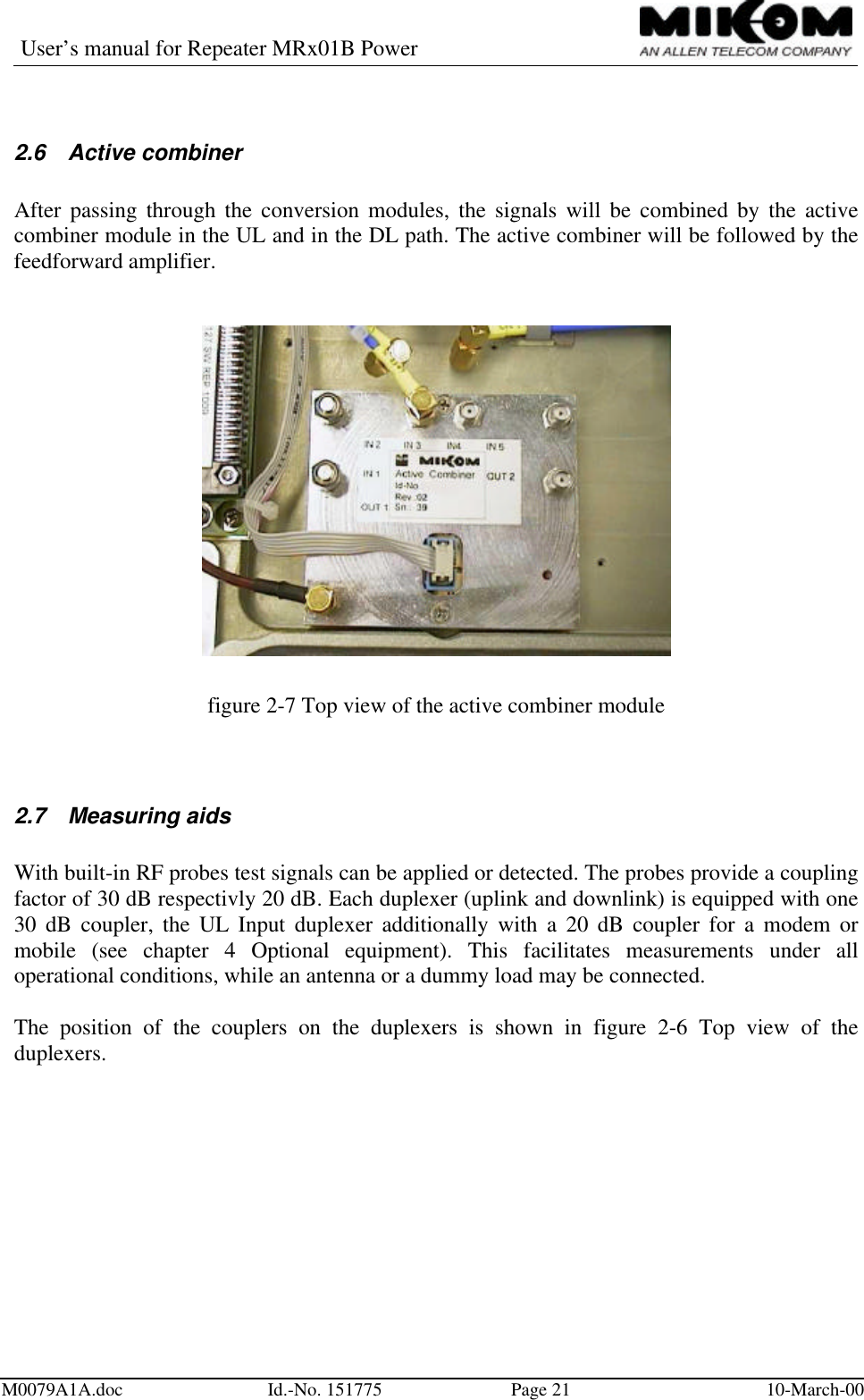
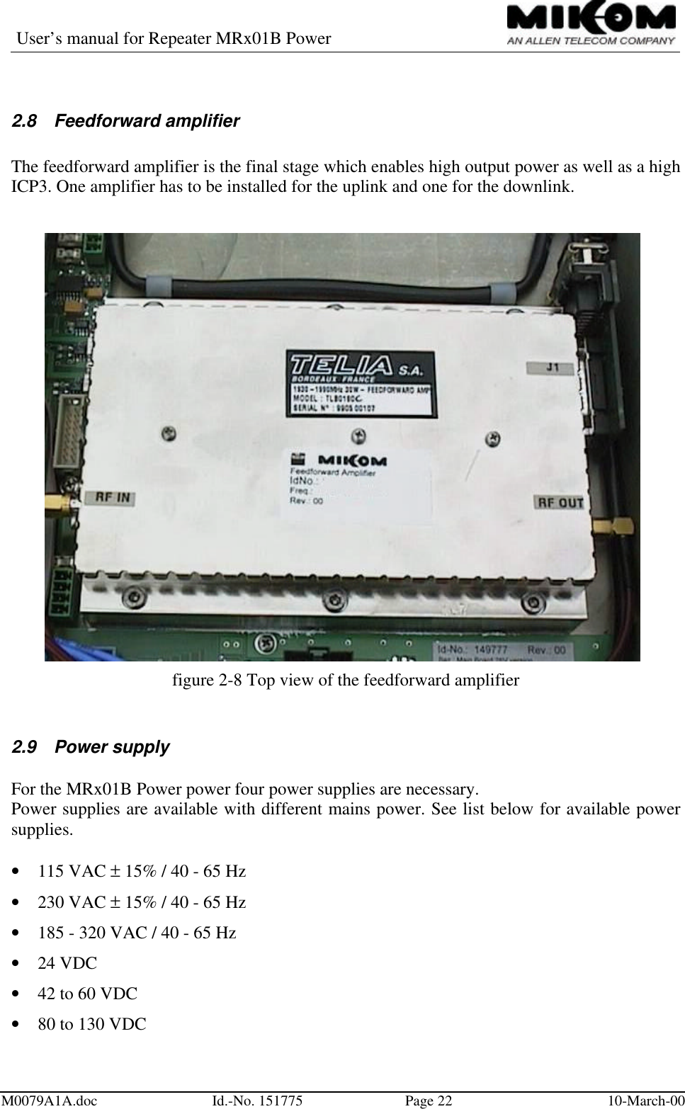
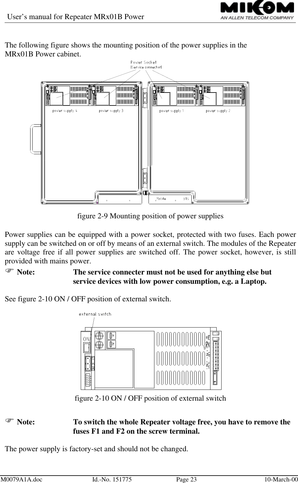
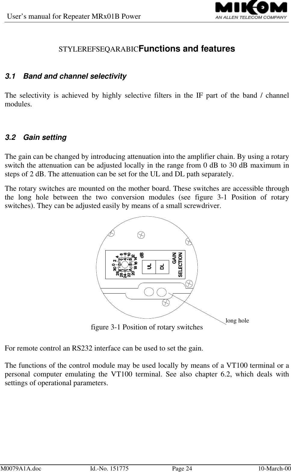
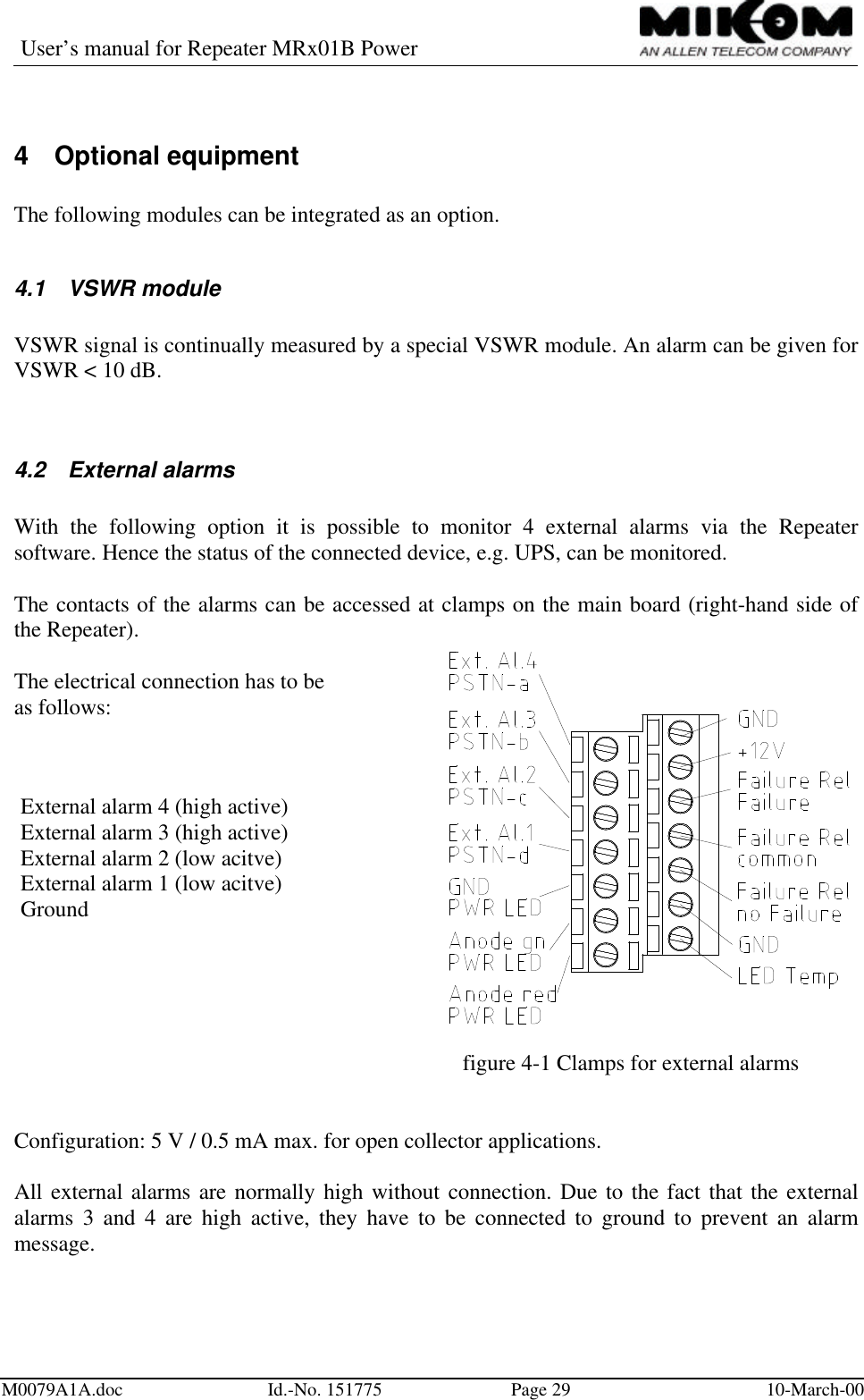
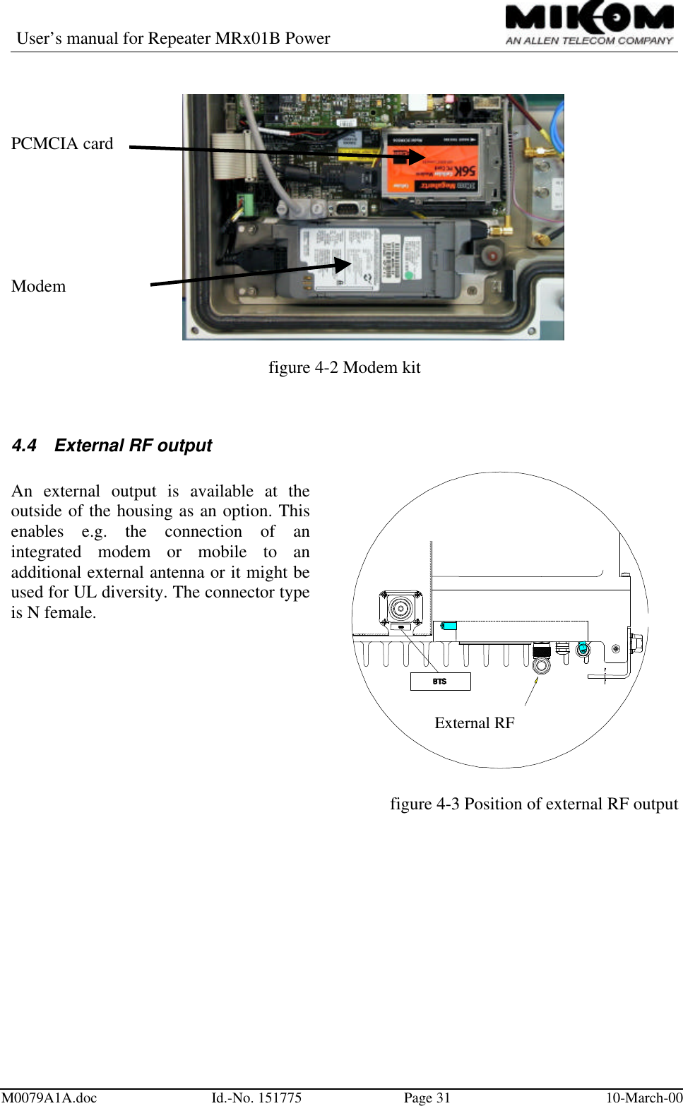
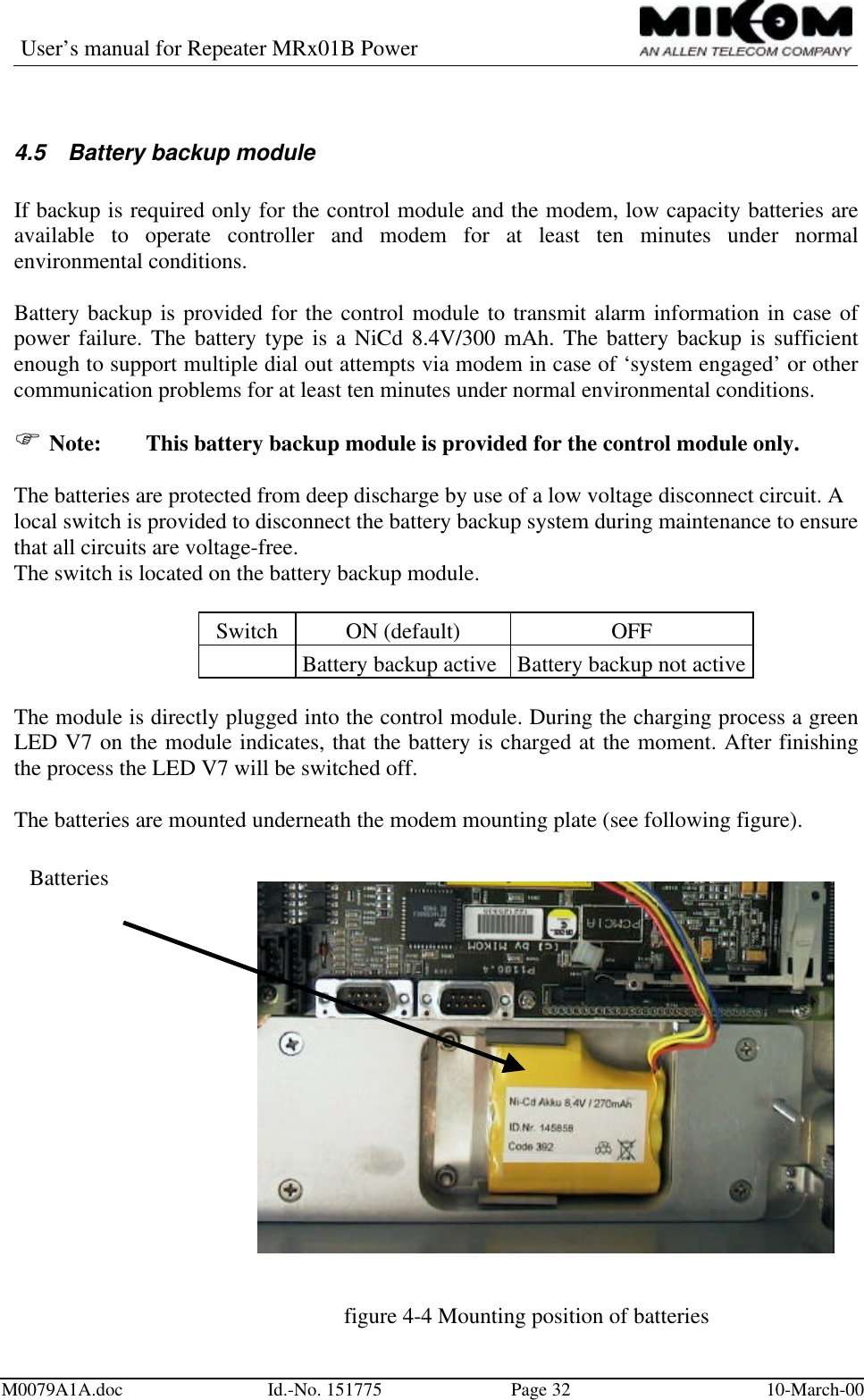
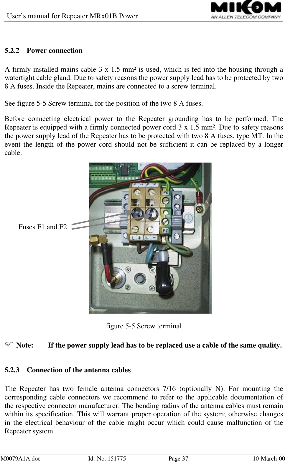
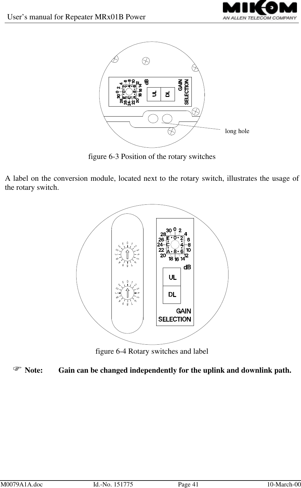
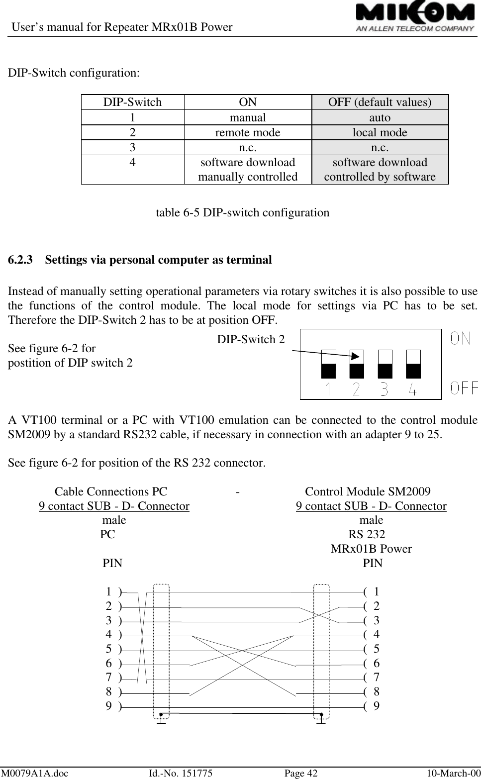
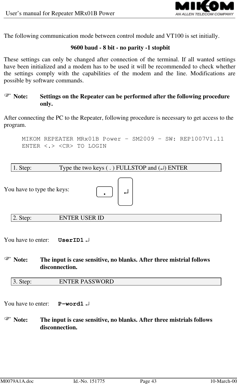
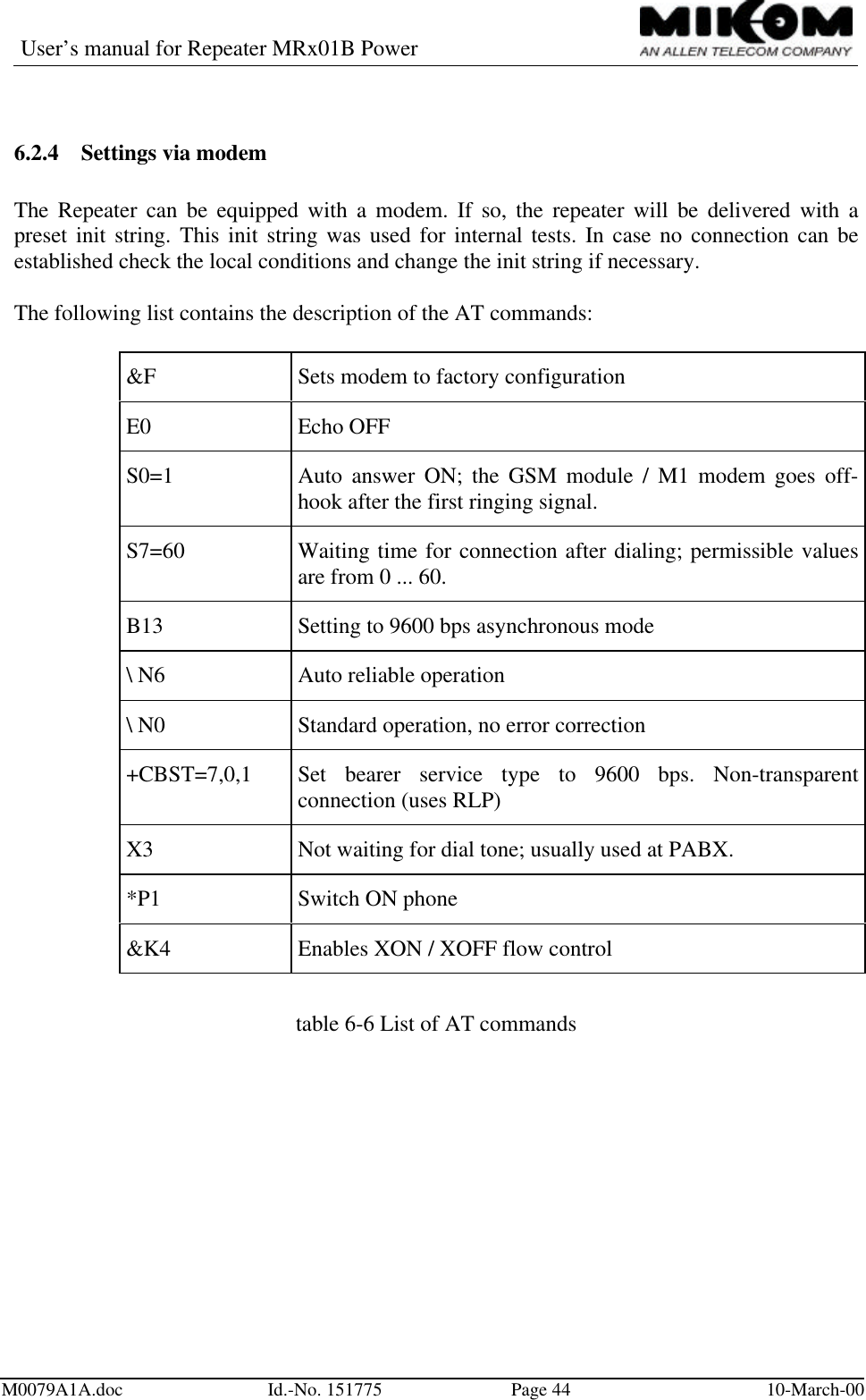
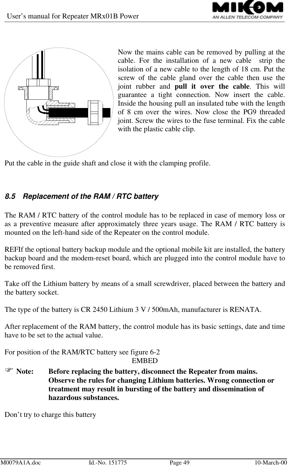
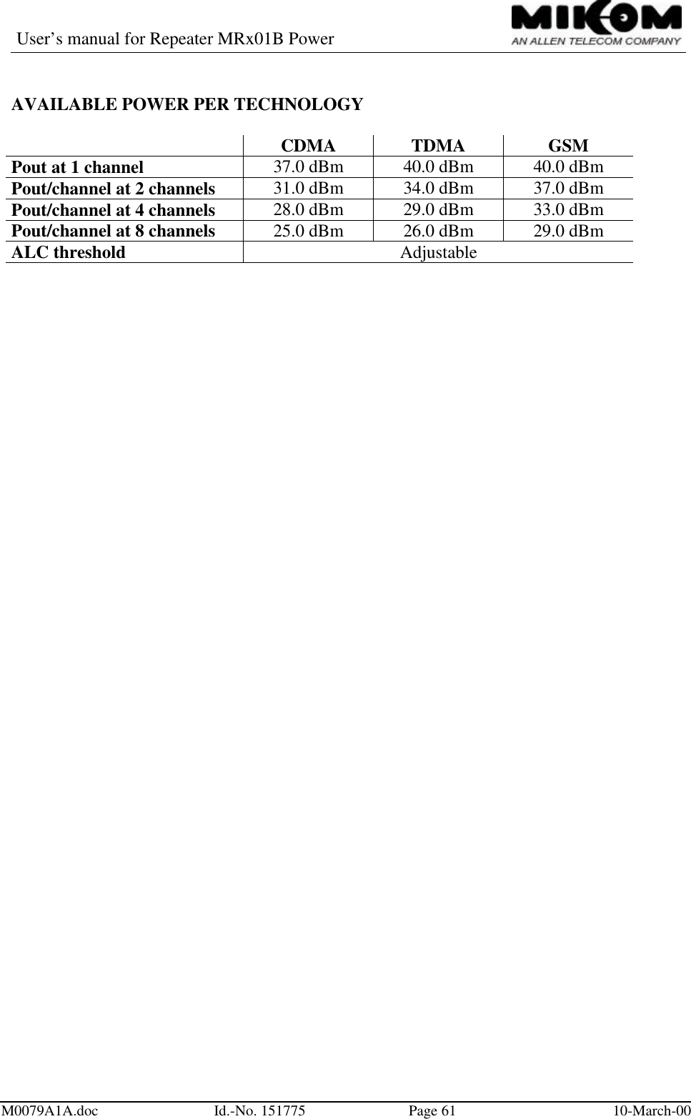
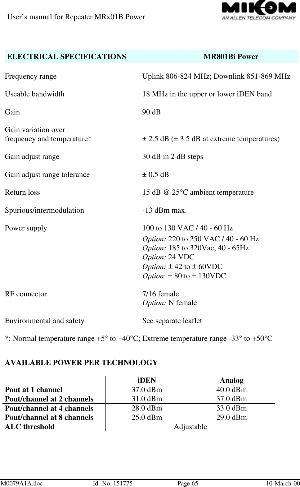
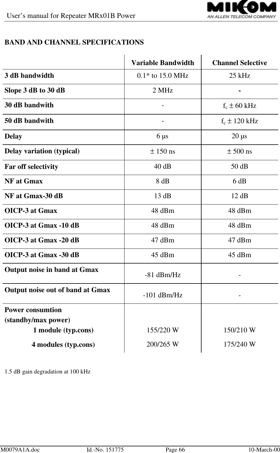
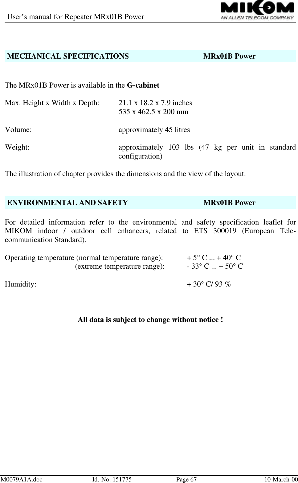
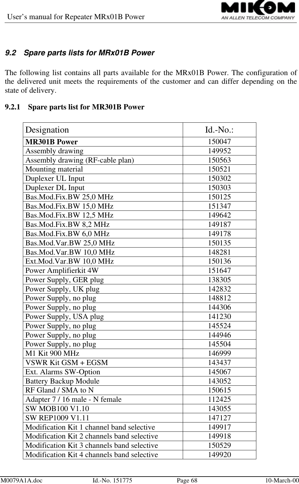
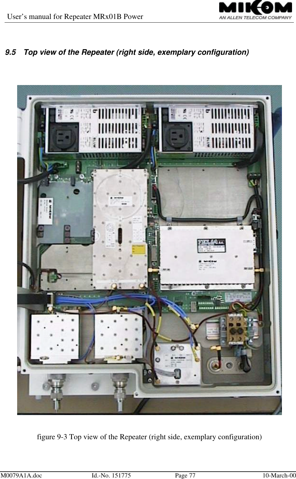
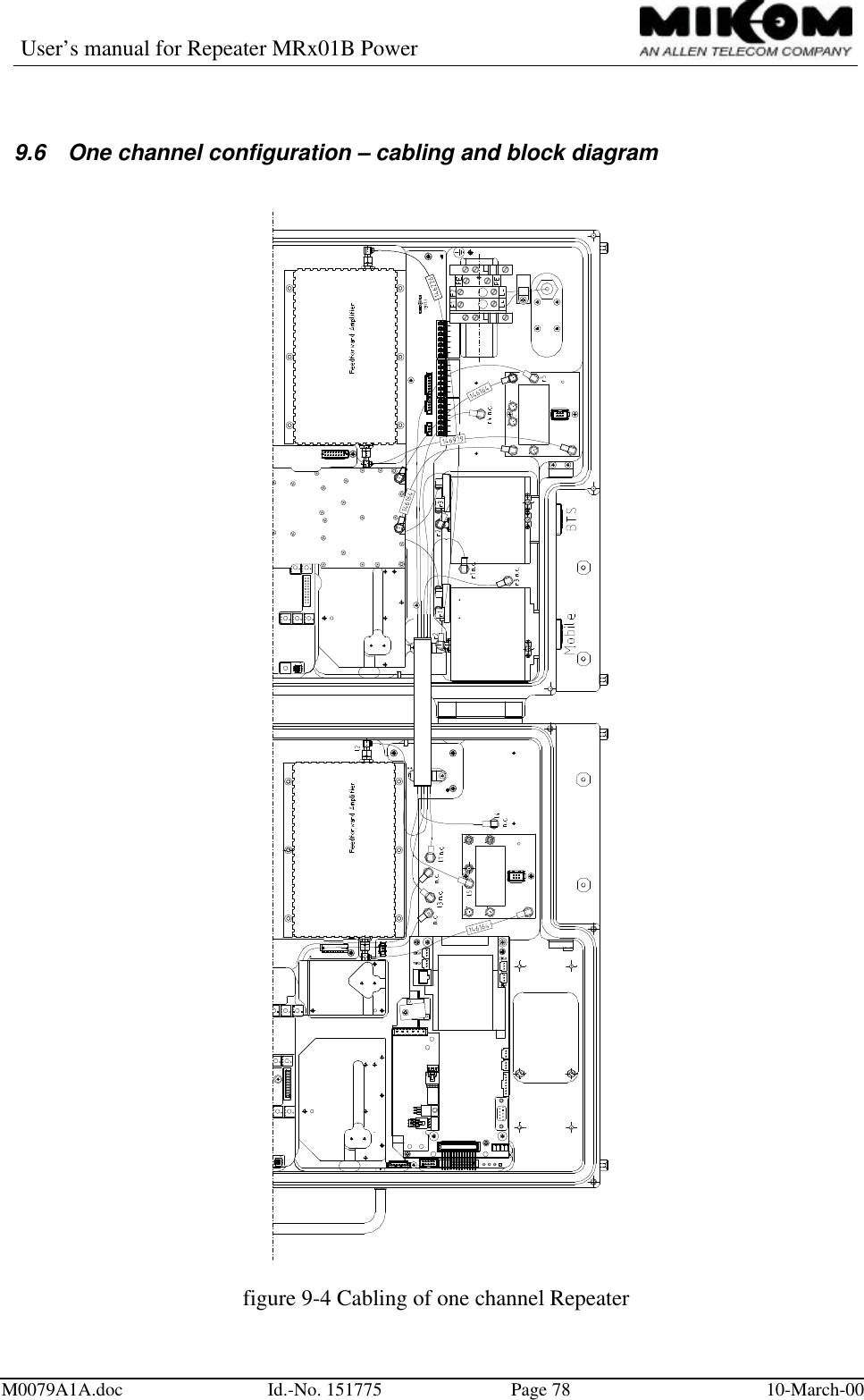
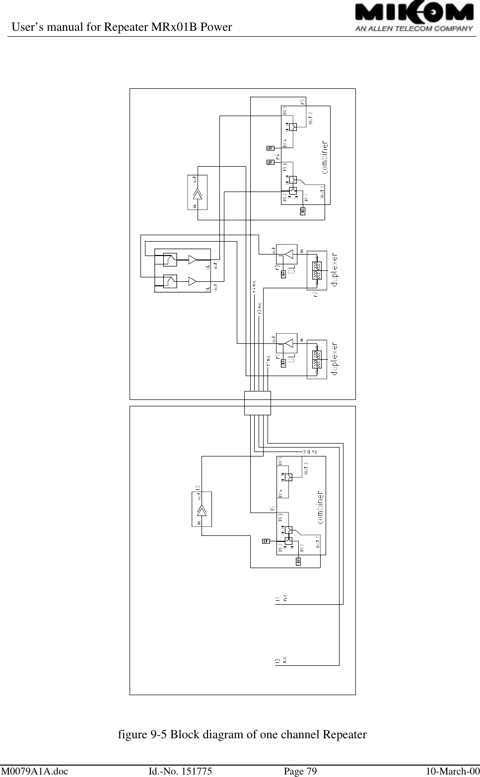
![User’s manual for Repeater MRx01B PowerM0079A1A.doc Id.-No. 151775 Page 60 10-March-00ELECTRICAL SPECIFICATIONS MR701B PowerFrequency range Id.No. UL frequency[MHz] DL frequency[MHz]148604 1850 – 1885 1930 – 1965151075 1865 – 1890 1945 - 1970148605 1875 – 1910 1955 - 1990Useable bandwidth 35 MHz (25 MHz in 151075) in the upper orlower PCS bandGain 90 dBGain variation overfrequency and temperature* ±2.5 dB (±3.5 dB at extreme temperatures)Gain adjust range 30 dB in 2 dB stepsGain adjust range tolerance ±0.5 dBReturn loss 15 dB @ 25°C ambient temperatureSpurious/intermodulation -13 dBm maxSpectral re-growth (CDMA only) -45 dBc (J-STD-008)Power supply 100-130 VAC / 40-60 HzOption: 15-24 VDC or 36-72 VDCOption: 220-250 VAC / 40-60 HzRF connector 7/16 femaleOption: N femaleEnvironmental and safety See separate leaflet*: Normal temperature range +5° to +40°C; Extreme temperature range -33° to +50°C](https://usermanual.wiki/Andrew-Wireless-Innovations-Group/RPT-MR801BI.Users-manual/User-Guide-125969-Page-60.png)