Andrew Wireless Innovations Group TFAM1719 Optical wireless distribution system User Manual Manual
Andrew Wireless Innovations Group Optical wireless distribution system Manual
UserManual.wiki
>
Andrew Wireless Innovations Group
>
TFAM1719 User Manual
>
Manual
Contents
1.
Manual
2.
Manual 2
Manual
Navigation menu
Upload a User Manual
Namespaces
Wiki Guide
HTML
PDF
Info
Views
User Manual
Discussion / Help
Navigation

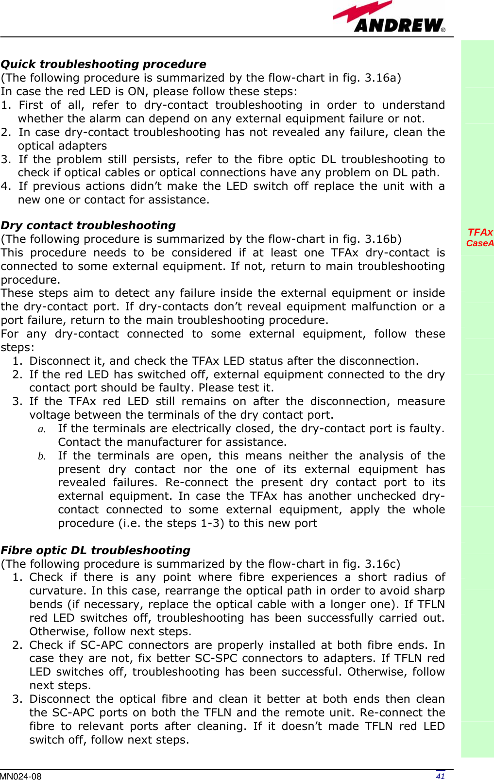
![42 User Manual4. Disconnect the optical SC-APC connector from remote unit DL port, and measure the output power POUT(DL) at the corresponding fibre end. Then, go to the TFLN side, disconnect the optical SC-APC connector from TFLN DL port and measure the input power PIN(DL) coming out of the TFLN DL port. Calculate the DL fibre attenuation ADL as ADL [dB] = PIN(DL) – POUT(DL) a. If ADL > 4dB, then the fibre optic cable has some problems. Replace it with a new one. b. If ADL < 4dB troubleshooting procedure has not identified the problem. Refer to supervision system or contact assistance. TFAx CaseA Fig. 3.16( a): Flow-chart describing the quick troubleshooting procedure on Case A TFAx startIs the red LED ON upon the TFAx? NoYes Yes NoVerify if any external equipment or any dry contact port have some problems. Refer to dry-contact troubleshooting (fig. 3.16b) Clean the SC-APC optical adapters and connectors NoYes endIs red LED upon TFAx still ON? Is red LED upon TFAx still ON? Optical cable or optical connections are supposed to have problems on DL path. Refer to fibre optic DL troubleshooting (fig. 3.16c)](https://usermanual.wiki/Andrew-Wireless-Innovations-Group/TFAM1719.Manual/User-Guide-800095-Page-44.png)
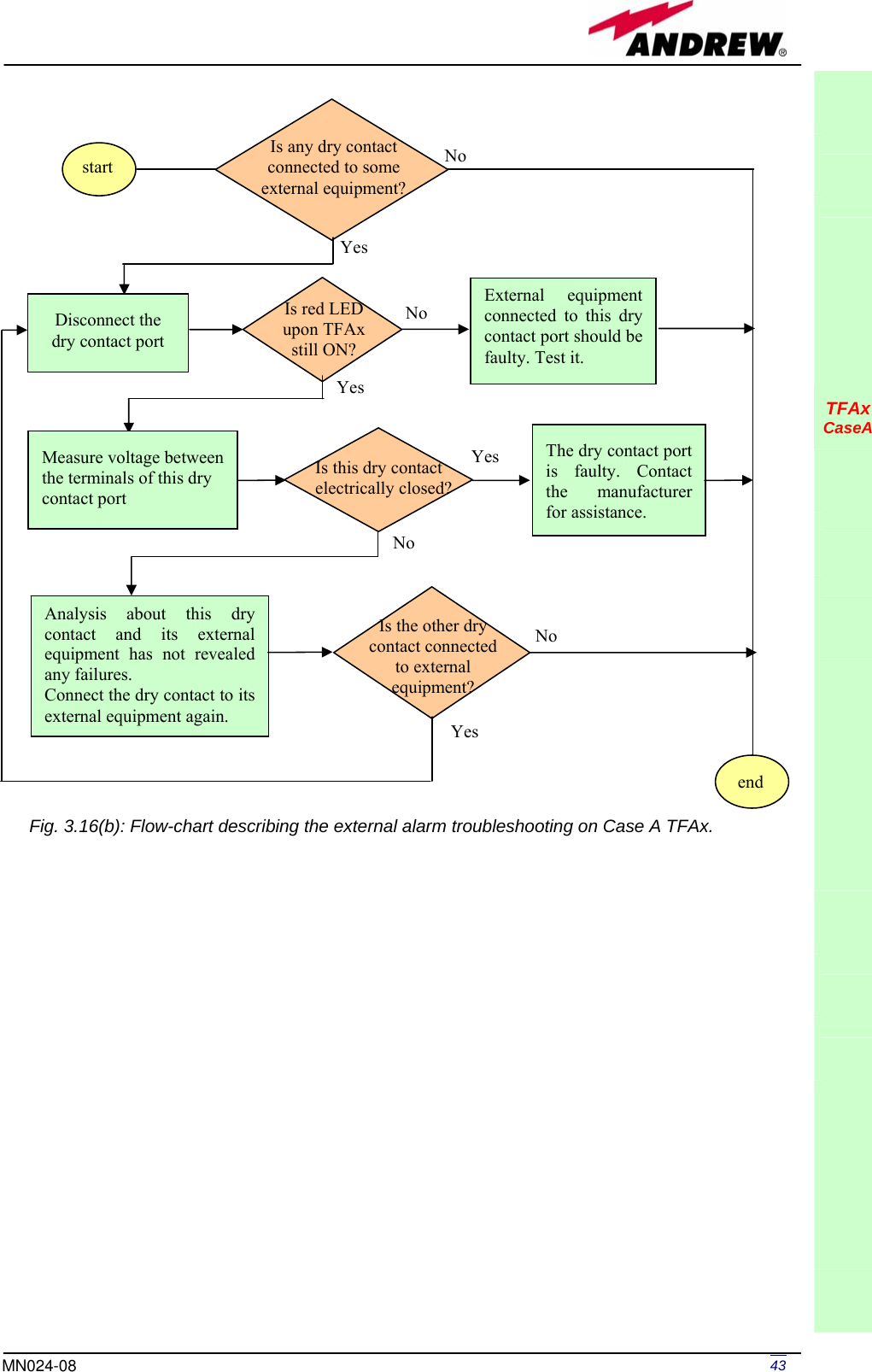
![44 User Manual TFAx CaseA Fig. 3.16 (c): Flow-chart describing the fibre optic DL troubleshooting start Is there any point where the fibre experiences a small radius of curvature? Rearrange the optical path to avoid sharp bends. If necessary replace the optical cable with a longer one. Is red LED upon remote unit still ON? Are SC-APC connectors properly installed at both fibre ends? Fix better SC-APC connectors YesNo No YesNoYes No YesDisconnect the optical SC-APC connector from remote unit DL port Clean optical SC-APC ports on both TFLN and remote unit.Disconnect fibre optic and clean it at both ends. Reconnect the fibre to relevant ports Measure the output power at corresponding fibre end. Measure the input power coming out of the TFLN DL port. Disconnect optical SC-APC connector from TFLN DL port. Calculate DL fibre attenuation ADL[dB]=input power - output power Is ADL > 4dB? Fibre optic cable has some problems. Replace it. Troubleshooting procedure has not identified the problem. Refer to supervision system or contact assistance end No YesNo Yes Is red LED upon remote unit still ON?Is red LED upon remote unit still ON? Go to TFLN side.](https://usermanual.wiki/Andrew-Wireless-Innovations-Group/TFAM1719.Manual/User-Guide-800095-Page-46.png)
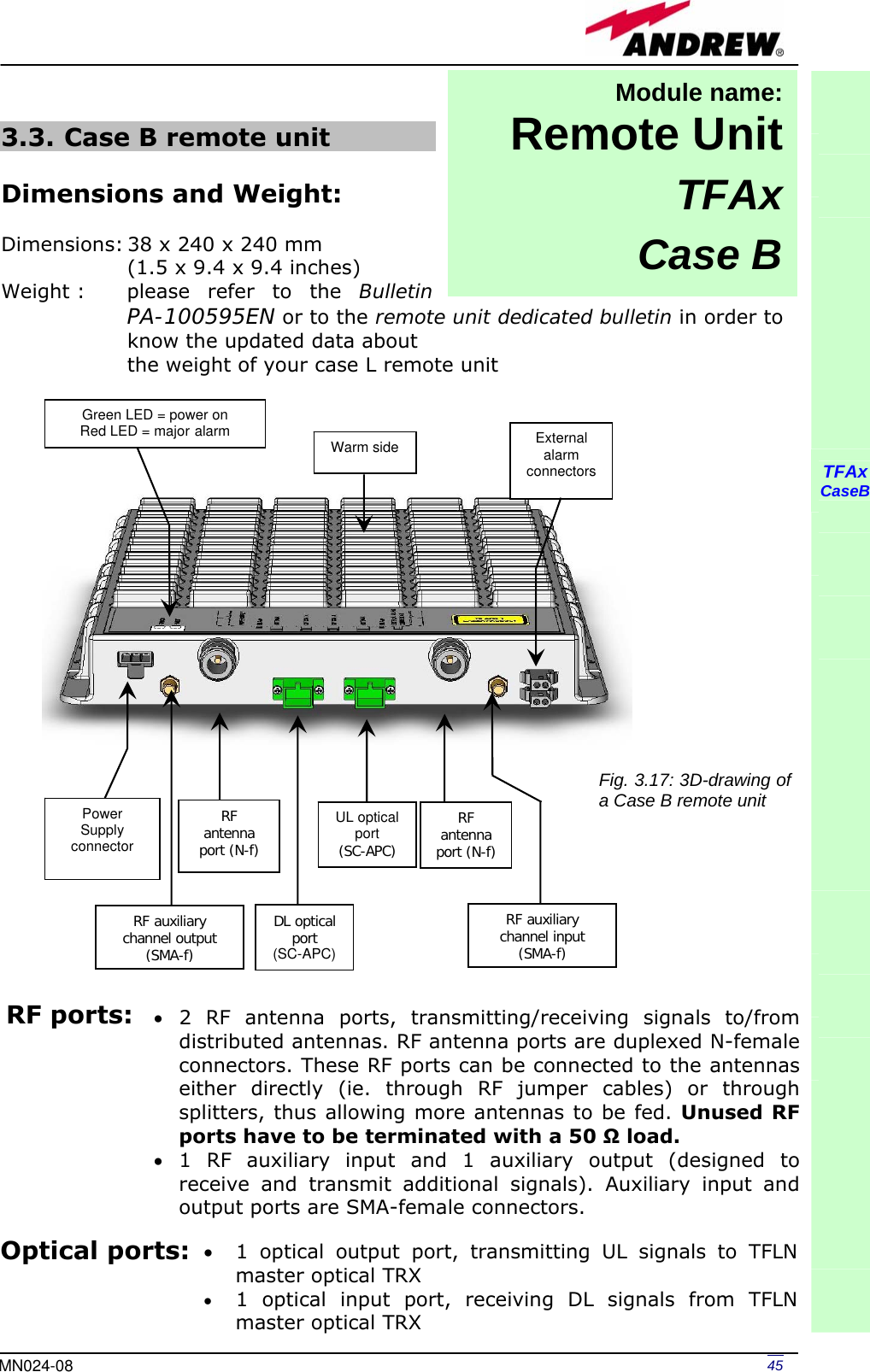
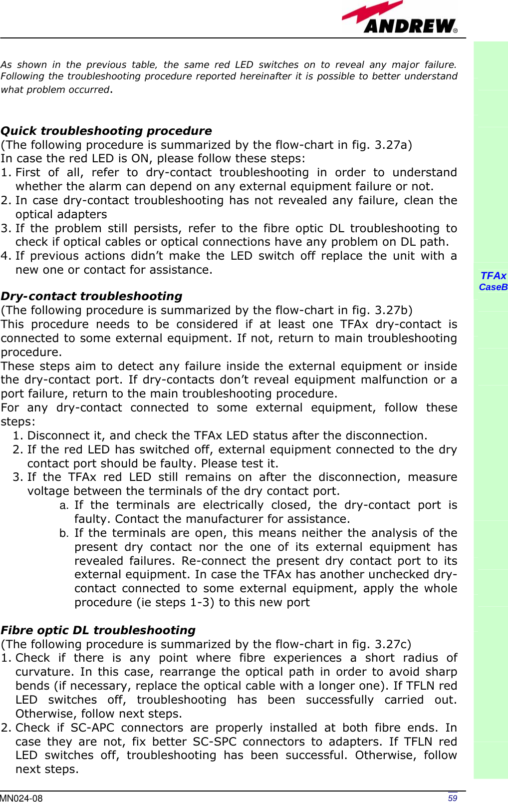
![60 User Manual3. Disconnect the optical fibre and clean it better at both ends then clean the SC-APC ports on both the TFLN and the remote unit. Re-connect the fibre to relevant ports after cleaning. If it doesn’t made TFLN red LED switch off, follow next steps. 4. Disconnect the optical SC-APC connector from remote unit DL port, and measure the output power POUT(DL) at the corresponding fibre end. Then, go to the TFLN side, disconnect the optical SC-APC connector from TFLN DL port and measure the input power PIN(DL) coming out of the TFLN DL port. Calculate the DL fibre attenuation ADL as ADL [dB] = PIN(DL) – POUT(DL) a. If ADL > 4dB, then the fibre optic cable has some problems. Replace it with a new one. b. If ADL < 4dB troubleshooting procedure has not identified the problem. Refer to supervision system or contact assistance. TFAx CaseB Fig. 3.27 (a): Flow-chart describing the quick troubleshooting procedure on TFAx Case B start Is the red LED ON upon the TFAx?NoYes Yes NoVerify if any external equipment or any dry contact port have some problems. Refer to dry-contact troubleshooting (fig. 3.27b) Clean the SC-APC optical adapters and connectors No Yes endIs red LED upon TFAx still ON? Is red LED upon TFAx still ON? Optical cable or optical connections are supposed to have problems on DL path. Refer to fibre optic DL troubleshooting (fig. 3.27c)](https://usermanual.wiki/Andrew-Wireless-Innovations-Group/TFAM1719.Manual/User-Guide-800095-Page-62.png)
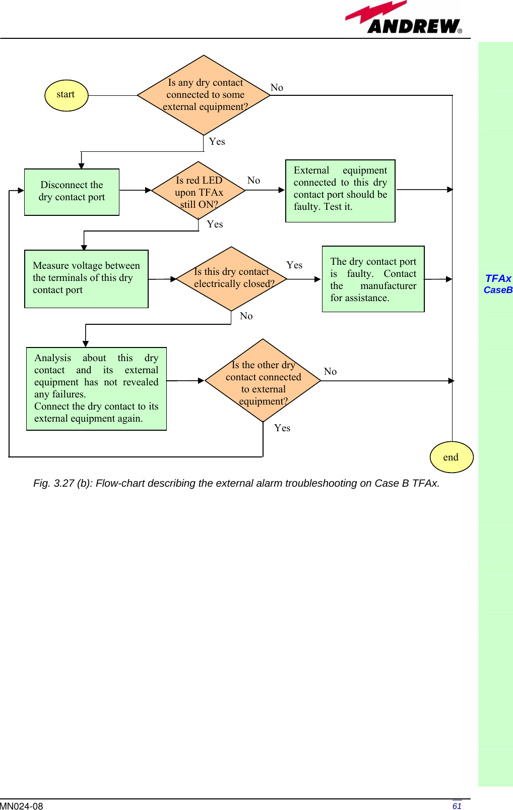
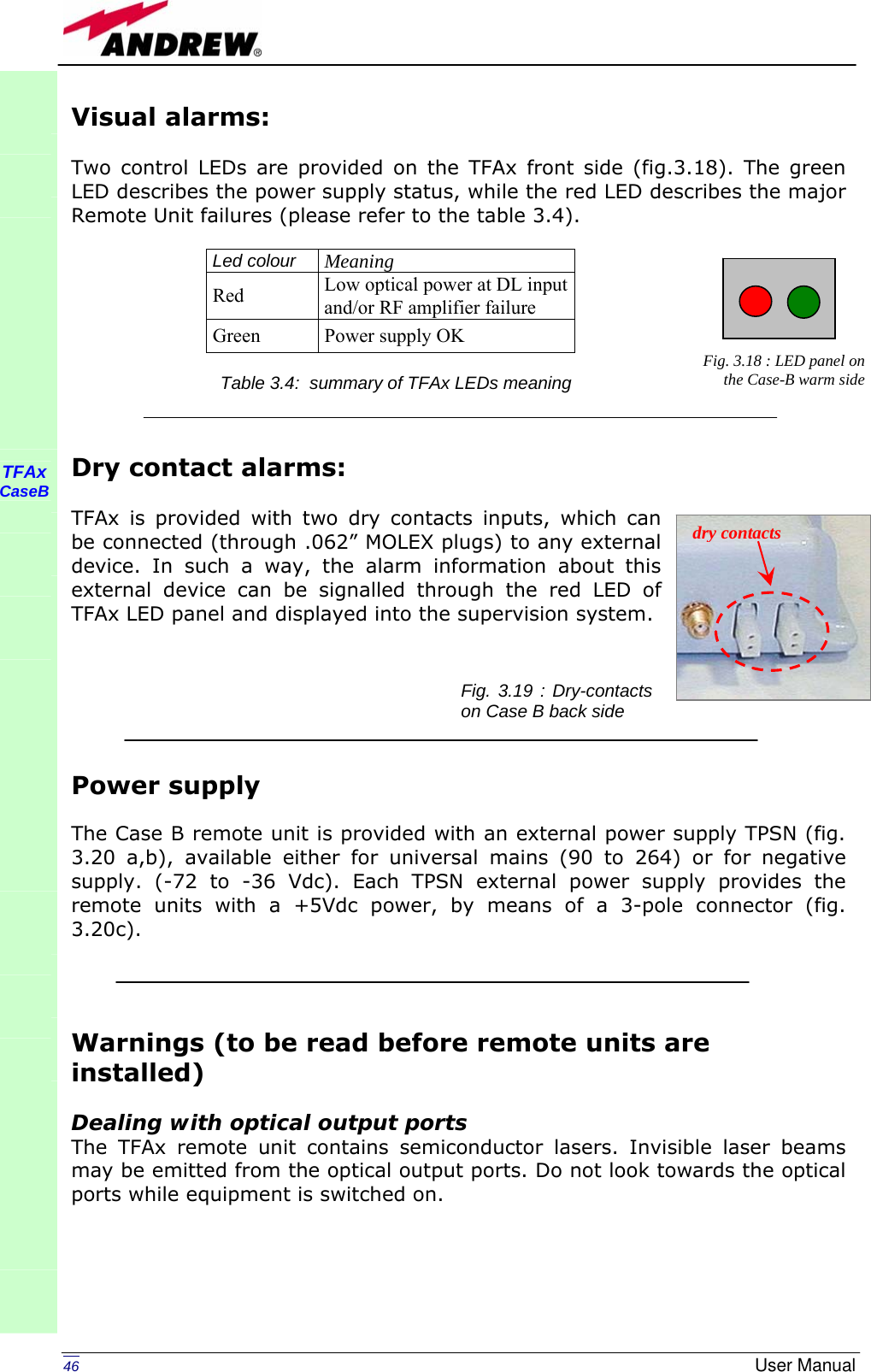
![62 User Manual TFAx CaseB Fig. 3.27 (c): Flow-chart describing the fibre optic DL troubleshooting start Is there any point where the fibre experiences a small radius of curvature? Rearrange the optical path to avoid sharp bends. If necessary replace the optical cable with a longer one. Is red LED upon remote unit still ON? Are SC-APC connectors properly installed at both fibre ends? Fix better SC-APC connectors YesNo No YesNoYes No YesDisconnect the optical SC-APC connector from remote unit DL port Clean optical SC-APC ports on both TFLN and remote unit.Disconnect fibre optic and clean it at both ends. Reconnect the fibre to relevant ports Measure the output power at corresponding fibre end. Measure the input power coming out of the TFLN DL port. Disconnect optical SC-APC connector from TFLN DL port. Calculate DL fibre attenuation ADL[dB]=input power - output power Is ADL > 4dB? Fibre optic cable has some problems. Replace it. Troubleshooting procedure has not identified the problem. Refer to supervision system or contact assistance end No YesNo Yes Is red LED upon remote unit still ON?Is red LED upon remote unit still ON? Go to TFLN side.](https://usermanual.wiki/Andrew-Wireless-Innovations-Group/TFAM1719.Manual/User-Guide-800095-Page-64.png)
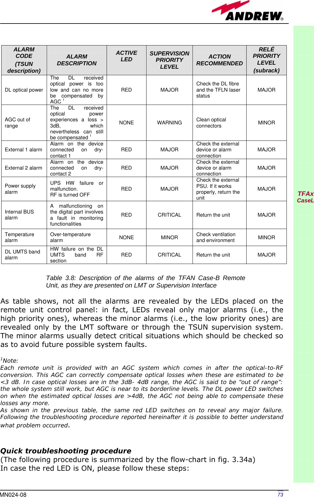
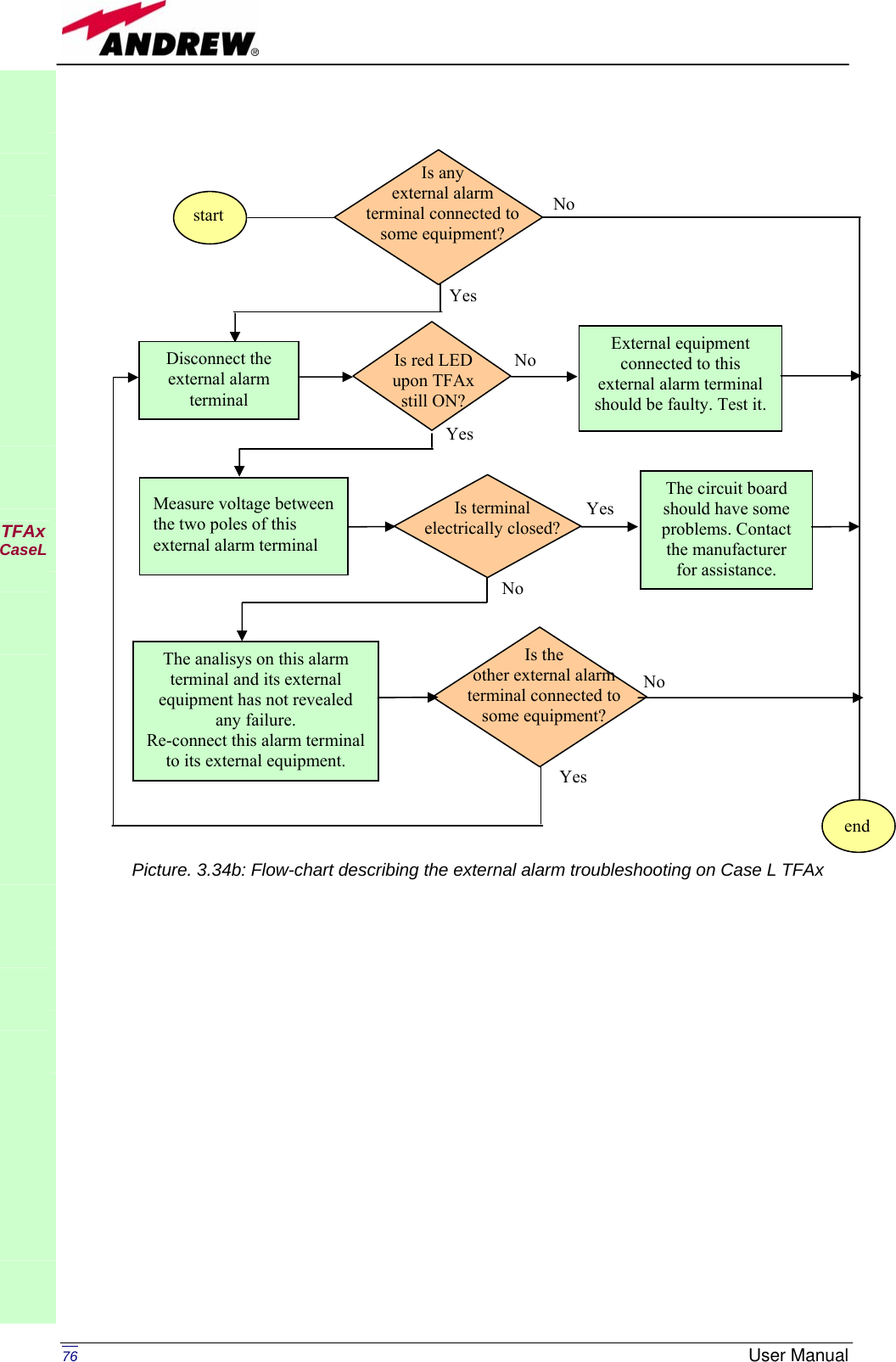
![75MN024-08 fibre to relevant ports after cleaning. If it doesn’t made TFLN red LED switch off, follow next steps. 4. Disconnect the optical SC-APC connector from remote unit DL port, and measure the output power POUT(DL) at the corresponding fibre end. Then, go to the TFLN side, disconnect the optical SC-APC connector from TFLN DL port and measure the input power PIN(DL) coming out of the TFLN DL port. Calculate the DL fibre attenuation ADL as ADL [dB] = PIN(DL) – POUT(DL) c. If ADL > 4dB, then the fibre optic cable has some problems. Replace it with a new one. d. If ADL < 4dB troubleshooting procedure has not identified the problem. Refer to supervision system or contact assistance. TFAx CaseL Fig. 3.34a: Flow-chart describing the quick troubleshooting procedure on Case LTFAxstartIs the red LED ON upon the TFAx? NoYes Yes NoVerify if any external equipment or any external alarm terminal has some problems. Refer to external alarm troubleshooting (fig.3.34b) Clean the SC-APC optical adapters and connectors NoYes endIs red LED upon TFAx still ON? Is red LED upon TFAx still ON? Optical cable or optical connections are supposed to have problems on DL path. Refer to fibre optic DL troubleshooting (fig. 3.34c)](https://usermanual.wiki/Andrew-Wireless-Innovations-Group/TFAM1719.Manual/User-Guide-800095-Page-77.png)
![77MN024-08 TFAx CaseL Fig. 3.34c: Flow-chart describing the fibre optic DL troubleshooting start Is there any point where the fibre experiences a small radius of curvature? Rearrange the optical path to avoid sharp bends. If necessary replace the optical cable with a longer one. Is the red LED upon the TFAx still ON? Are SC-APC connectors properly installed at both fibre ends? Fix better SC-APC connectors YesNo No YesNoYes No YesDisconnect the optical SC-APC connector from remote unit DL port Clean optical SC-APC ports on both TFLN and remote unit.Disconnect fibre optic and clean it at both ends. Reconnect the fibre to relevant ports Measure the output power at corresponding fibre end. Measure the input power coming out of the TFLN DL port. Disconnect optical SC-APC connector from TFLN DL port. Calculate DL fibre attenuation ADL[dB]=input power - output power Is ADL > 4dB? Fibre optic cable has some problems. Replace it. Troubleshooting procedure has not identified the problem. Refer to supervision system or contact assistance end No YesNoYesis the red LED upon TFAx still ON? Is red LED upon remote unit still ON? Go to TFLN side.](https://usermanual.wiki/Andrew-Wireless-Innovations-Group/TFAM1719.Manual/User-Guide-800095-Page-79.png)
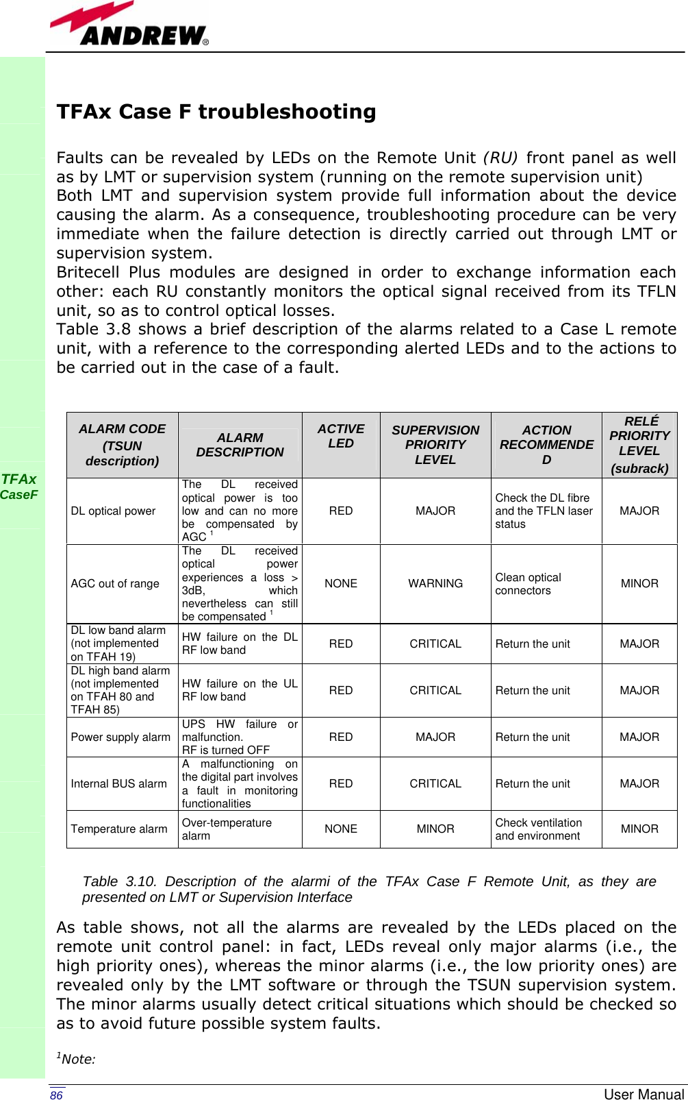
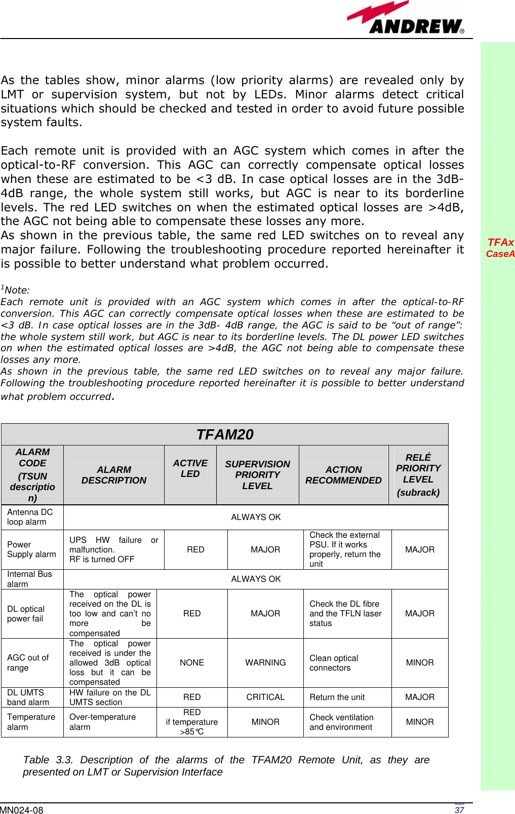
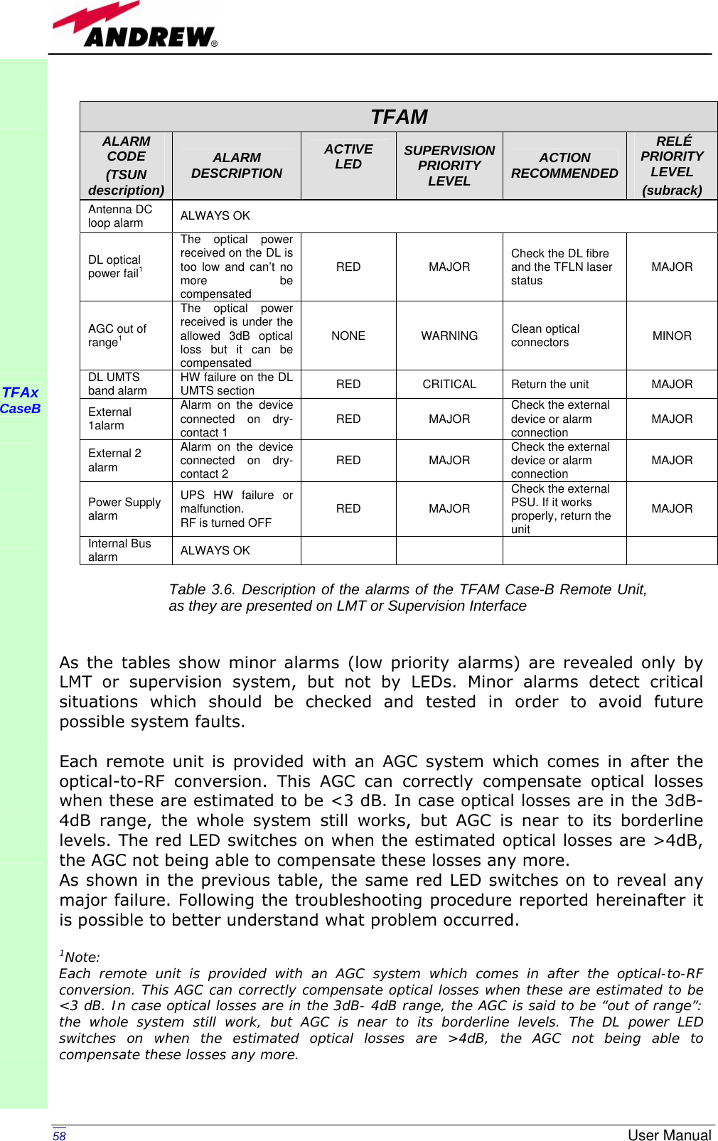
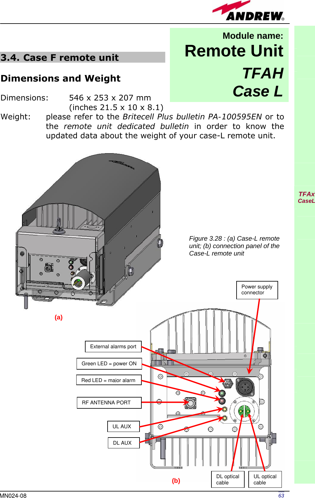
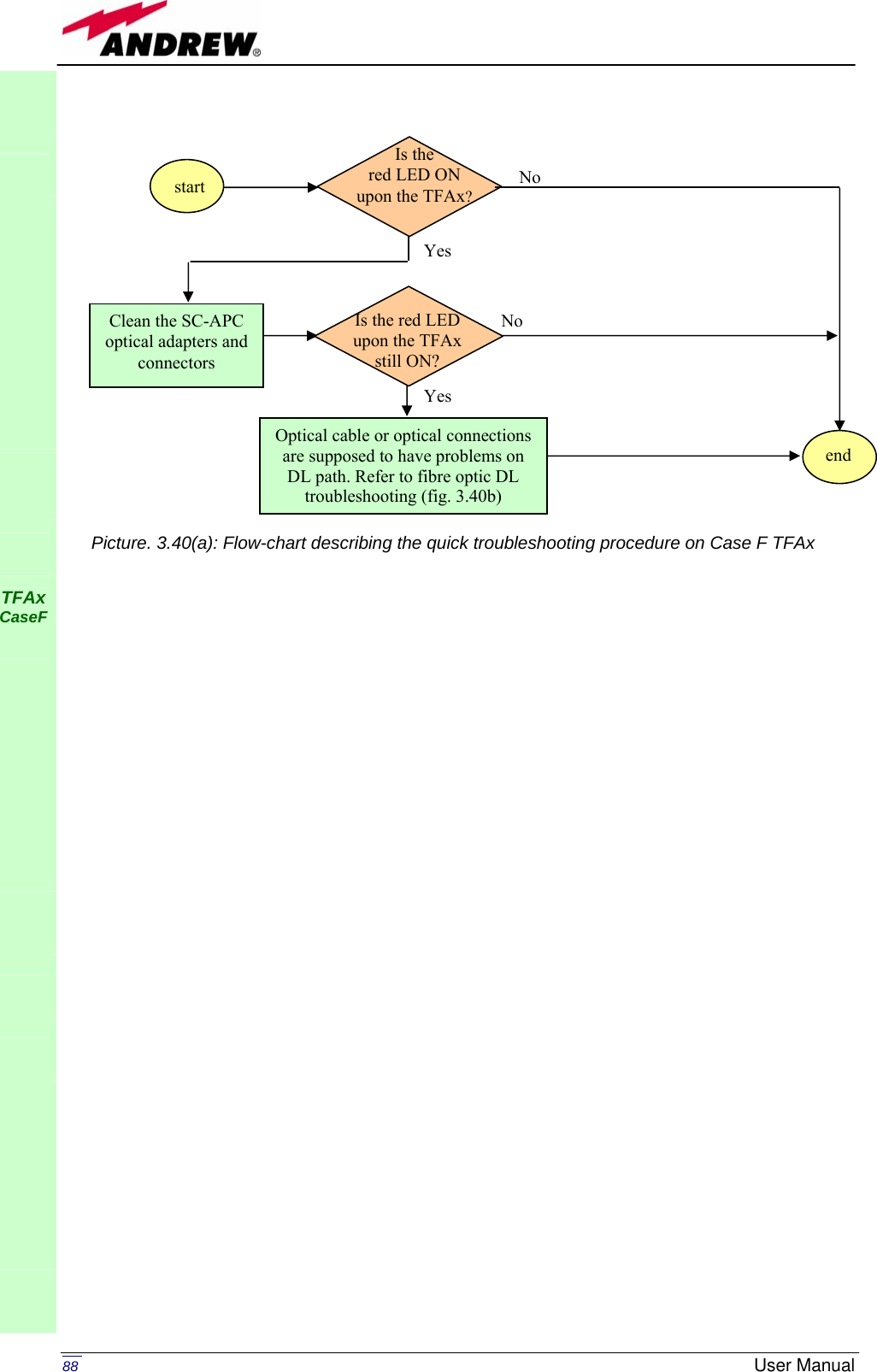
![87MN024-08 Each remote unit is provided with an AGC system which comes in after the optical-to-RF conversion. This AGC can correctly compensate optical losses when these are estimated to be <3 dB. In case optical losses are in the 3dB- 4dB range, the AGC is said to be “out of range”: the whole system still work, but AGC is near to its borderline levels. The DL power LED switches on when the estimated optical losses are >4dB, the AGC not being able to compensate these losses any more. As shown in the previous table, the same red LED switches on to reveal any major failure. Following the troubleshooting procedure reported hereinafter it is possible to better understand what problem occurred. Quick troubleshooting procedure (The following procedure is summarized by the flow-chart in fig. 3.40a) In case the red LED is ON, please follow these steps: 1. First of all, clean the optical adapters 2. If the problem still persists, refer to the fibre optic DL troubleshooting to check if optical cables or optical connections have any problem on DL path. 3. If previous actions didn’t make the LED switch off replace the unit with a new one or contact for assistance. Fibre optic DL troubleshooting (The following procedure is summarized by the flow-chart in fig. 3.40b) 1. Check if there is any point where fibre experiences a short radius of curvature. In this case, rearrange the optical path in order to avoid sharp bends (if necessary, replace the optical cable with a longer one). If TFLN red LED switches off, troubleshooting has been successfully carried out. Otherwise, follow next steps. 2. Check if SC-APC connectors are properly installed at both fibre ends. In case they are not, fix better SC-SPC connectors to adapters. If TFLN red LED switches off, troubleshooting has been successful. Otherwise, follow next steps. 3. Disconnect the optical fibre and clean it better at both ends then clean the SC-APC ports on both the TFLN and the remote unit. Re-connect the fibre to relevant ports after cleaning. If it doesn’t made TFLN red LED switch off, follow next steps. 4. Disconnect the optical SC-APC connector from remote unit DL port, and measure the output power POUT(DL) at the corresponding fibre end. Then, go to the TFLN side, disconnect the optical SC-APC connector from TFLN DL port and measure the input power PIN(DL) coming out of the TFLN DL port. Calculate the DL fibre attenuation ADL as ADL [dB] = PIN(DL) – POUT(DL) a. If ADL > 4dB, then the fibre optic cable has some problems. Replace it with a new one. b. If ADL < 4dB troubleshooting procedure has not identified the problem. Refer to supervision system or contact assistance. TFAx CaseF](https://usermanual.wiki/Andrew-Wireless-Innovations-Group/TFAM1719.Manual/User-Guide-800095-Page-89.png)
![89MN024-08 TFAx CaseF Fig. 3.40(b): Flow-chart describing the fibre optic DL troubleshooting start Is there any point where the fibre experiences a small radius of curvature? Rearrange the optical path to avoid sharp bends. If necessary replace the optical cable with a longer one. Is the red LED upon the TFAx still ON? Are SC-APC connectors properly installed at both fibre ends? Fix better SC-APC connectors YesNo No YesNoYes No YesDisconnect the optical SC-APC connector from remote unit DL port Clean optical SC-APC ports on both TFLN and remote unit.Disconnect fibre optic and clean it at both ends. Reconnect the fibre to relevant ports Measure the output power at corresponding fibre end. Measure the input power coming out of the TFLN DL port. Disconnect optical SC-APC connector from TFLN DL port. Calculate DL fibre attenuation ADL[dB]=input power - output power Is ADL > 4dB? Fibre optic cable has some problems. Replace it. Troubleshooting procedure has not identified the problem. Refer to supervision system or contact assistance end No YesNoYesIs the red LED upon the TFAx still ON? Is the red LED upon the TFAx still ON? Go to TFLN side.](https://usermanual.wiki/Andrew-Wireless-Innovations-Group/TFAM1719.Manual/User-Guide-800095-Page-91.png)

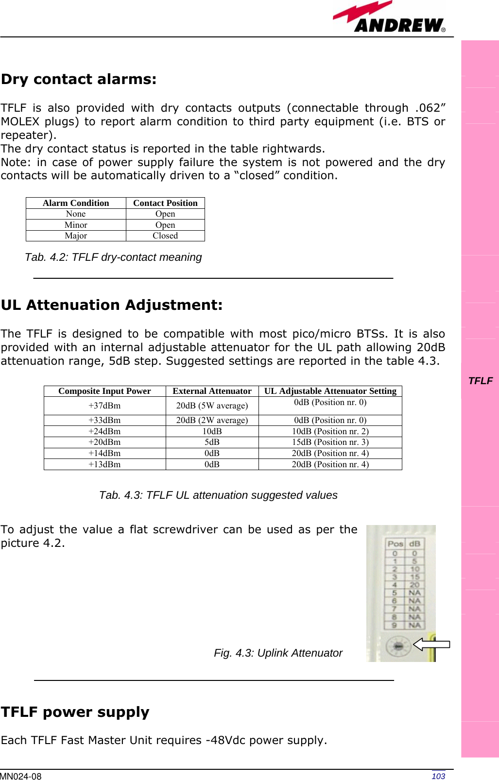
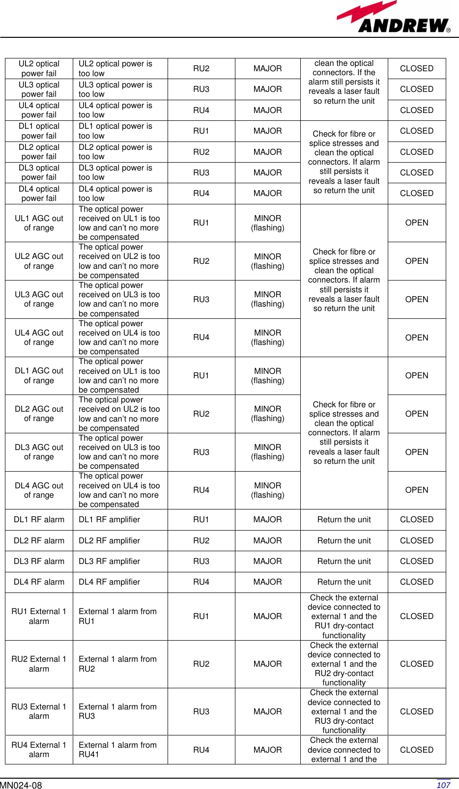
![109MN024-08 2. Check if the SC-APC connectors are properly installed at both fibre ends (i.e. TFLF and TFAx ports). If not fix better SC-SPC connectors to relevant adapters. If this makes the TFLF LED switch off, troubleshooting has been successful. Otherwise, follow next steps. 3. Disconnect the optical fibre and clean it at both fibre ends (i.e. TFLF side and TFAx side) then reconnect the fibre to relevant ports. In case this makes the TFLF LED switch off, troubleshooting has been successful. Otherwise, follow next steps. 4. Disconnect the optical SC-APC connector from TFLF UL port, and measure the output power POUT(UL) at corresponding fibre end. Then, go to the TFAx side, disconnect the optical SC-APC connector from TFAx UL port and measure the input power PIN(UL) coming out of the TFAx UL port. 5. Calculate the UL fibre attenuation AUL as: AUL [dB] = PIN(UL) – POUT(UL) a. If AUL > 4dB, the fibre optic cable has some problems or cable path is too long. Replace it. b. If AUL < 4dB, then TFAx remote unit should be faulty. Before replacing it, contact for assistance TFLF](https://usermanual.wiki/Andrew-Wireless-Innovations-Group/TFAM1719.Manual/User-Guide-800095-Page-111.png)
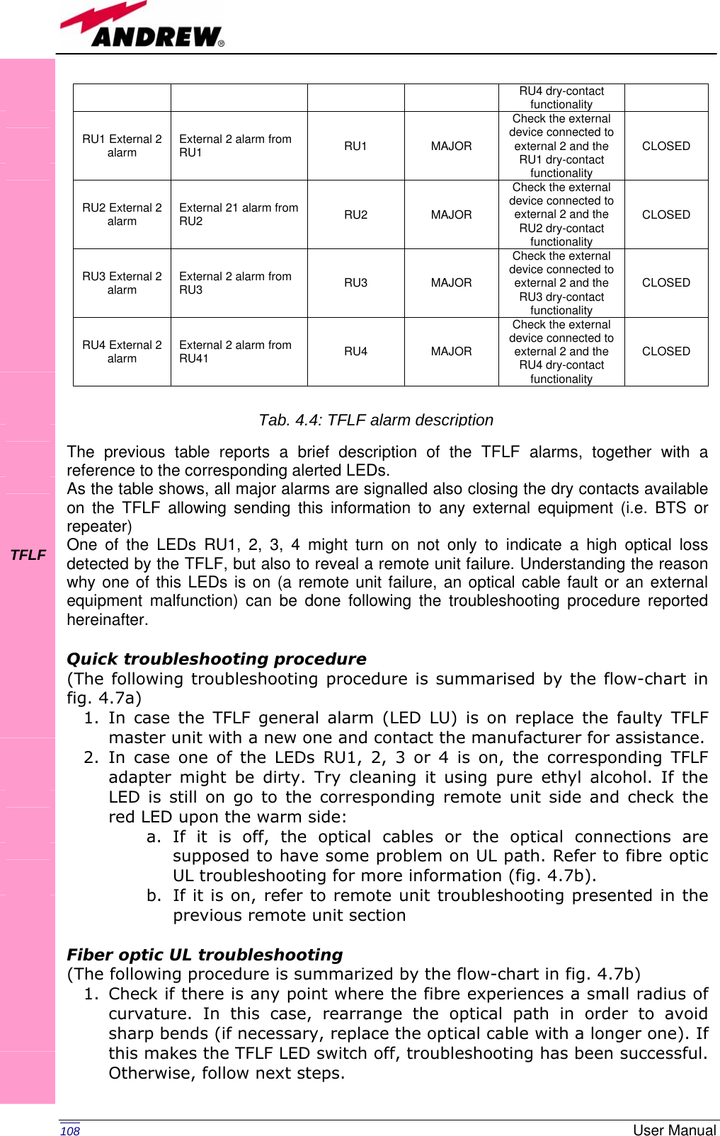
![111MN024-08 TFLF Fig. 4.7 (b): Flow-chart describing the fibre optic UL troubleshooting start Is there any small radius of curvature of the fibre? Rearrange the optical path in order to avoid sharp bends. If necessary replace the optical cable with a longer one.Is the red LED upon TFLF still ON? Are SC-APC connectors properly installed at both fibre ends? Fix SC-APC connectors properly to adapters. YesNo No YesNoYes NoYesDisconnect the optical SC-APC connector from TFLN UL port. Clean the optical SC-APC ports both on TFLN and TFAx side. Disconnect the optical fibre and clean it at both ends. Re-connect the fibre to relevant ports.Measure the output power at the corresponding fibre end Measure the input power entering the fibre. Go to the TFAx side Disconnect the optical SC-APC connector from TFAx UL port. Calculate the UL fibre attenuation: AUL[dB]=input power - output power Is AUL > 4dB? Fibre optic cable has some problems. Replace it. The TFAx remote unit should be faulty. Before replacing it, contact for assistance. end No YesNo Yes Is the red LED upon TFLF still ON?Is the red LED upon TFLF still ON?](https://usermanual.wiki/Andrew-Wireless-Innovations-Group/TFAM1719.Manual/User-Guide-800095-Page-113.png)