Andrew Wireless Innovations Group TFAM1719 Optical wireless distribution system User Manual Manual
Andrew Wireless Innovations Group Optical wireless distribution system Manual
Contents
- 1. Manual
- 2. Manual 2
Manual
User Manual
MN024-08
PLU S

1
MN024-08
© Copyright Andrew Wireless Systems Srl
This publication is issued to provide outline information and is not aimed
to be part of any offer and contract.
The Company has a policy of continuous product development and
improvement and we therefore reserve the right to vary information
quoted without prior notice.
System and Customer care is available world-wide through our network of
Experts.
The company is certified ISO 9001 and ISO14000.
Andrew Wireless Systems Srl
Via Pier De Crescenzi 40
48018 Faenza, Italy
Tel: +39 0546 697111
Fax: +39 0546 682768
www.andrew.com

INDEX
0. Index 2
1. Introducing Britecell Plus 4
1.1 The Features 5
1.2 Brief Description of Britecell Plus 5
1.3 Britecell Plus features 6
1.4 Britecell Plus typical applications 7
2. Equipment Overview 9
2.1 The Britecell Plus Remote Unit and its relevant accessories 10
2.2 the Britecell Plus Master Unit 12
2.2.1 The Fast Master Unit 12
2.2.2 The Rack-based Master Unit 12
2.3 Block diagrams 16
3. TFAx Remote Unit 22
3.1 Introduction 23
3.2 Case A remote unit 25
3.3 Case B remote unit 45
3.4 Case L remote unit 63
3.5 Case F remote unit 79
3.6 Wi-Fi Booster TFBW 90
4. Fast Master Unit 100
5. Rack based master unit 113
5.1 19” Subrack TPRNx4 114
5.2 Master Optical TRX, TFLN 126
5.3 Two-way splitter/combiner TLCN2 138
5.4 Four-way splitter/combiner TLCN4 142
5.5 RF dual band coupler TLDN 146
5.6 RF tri-band coupler TLTN 150
5.7 RF Duplexer TDPX 154
5.8 Base Station Interface TBSI 158
5.9 Power Limiter TMPx-10 162
5.10 Wi-Fi Local Interface 168
5.11 The interconnect link (i-link) 172
5.11.1 Introduction 173
5.11.2 TILx-HL Interconnect link 177
5.11.3 TILx-HLW Interconnect link 195
5.12 Remote Supply Unit TRS/TRSN 216
6. Warning and Safety Requirements 222
6.1 Environmental conditions 223
6.2 Installation site Features 223
6.3 Safety and Precautions during Installation or maintenance 224
6.4 Power Supply Connection 225
2 User Manual

6.5 Safety and Precautions for Lasers 226
6.6 Health and Safety Warnings 226
6.7 Electromagnetic Fields and RF Power 227
6.7 Warning Labels 230
7. Technical support 231
7.1 Returning Equipment 231
Appendix A: System Commissioning 233
Appendix B: EU Guidelines for WEEE disposal 237
3
MN024-08

4 User Manual
1. Introducing Britecell Plus

5
MN024-08
1.1 The Features
Britecell Plus is an innovative platform designed in order to provide an
effective and flexible coverage to a large variety of indoor scenarios.
Thanks to its high modularity, its low power consumption, and its full-
transparency to protocols and modulation formats, Britecell Plus is the perfect
plug&play solution to distribute any wireless standard (including GSM, GPRS,
EDGE, CDMA, WCDMA, and WLAN IEEE 802.11b) to the in-building
environments requiring reliable and interference-free communications, as well
as high traffic capacity and maximum flexibility about future expansions.
These unique features make the Britecell Plus platform suitable also for
applications to critical areas experiencing difficulties in establishing and
keeping phone calls, while its compact design always guarantees a minimum
aesthetic impact.
1.2 Brief Description of Britecell Plus
Britecell Plus is a Distributed Antenna System (DAS) based on the Radio-over-
Fibre (RoF) technology, and capable of carrying wireless mobile signals
through the 800MHz - 2500MHz frequency range regardless of their protocol
and their modulation format.
The system has two basic components, a Master Unit and a Remote Unit. The
Master Unit is made of one or more subracks typically connected to the BTS
(Base Tranceiver Station) through either a repeater (RF interface) or a coaxial
cable.
Each Remote Unit is connected with a dedicated pair of single-mode optical
fibres (one for UL and one for DL) to the Master Unit. These optical fibres work
on 1310 nm wavelenght and provide low losses and almost unlimited
bandwidth, available for future system developments.
Britecell Plus is a modular system whose basic components are:
• one Master Unit made of one or more subracks, each providing 12
module slots. Each slot can host either an active or a RF passive device
(chosen among the wide range of Britecell Plus options), in order to
meet the planned design requirements;
• a variable number of Remote Units (TFAx), whose function is feeding
the antenna passive network;
• a proper number of indoor antennas, suitable to provide radio coverage
to the area. Britecell Plus is fully compatible with any type of indoor
antennas;
• the optical cables required to connect the 19” subracks to the TFAx.

6 User Manual
Fig. 1.1: Britecell Plus system block diagram.
1.3 Britecell Plus Features
The following lines report a brief summary of Britecell Plus main features:
• multiband 2G, 2.5G and 3G – 802.11b WLAN compatible: Britecell
Plus is completely transparent to any transmission protocol and
modulation format, and it can distribute any 2G, 2.5G, 3G wireless
standard. In addition, it allows to carry also the WLAN (802.11b/g)
service over the same infrastructure;
• modular configuration for flexible design: by properly setting some
parameters like the amount of RUs and the antenna locations, the
Britecell Plus architecture can follow the environment specific features in
order to obtain the most effective radio-coverage of the indoor area.
The modularity of the system allows easy modifications for future
growth and increasing traffic;
• easy to install: the intelligent plug & play Britecell Plus system
includes an Automatic Gain Control (AGC), that eliminates system gain
variations regardless of optical loss. This avoids the need for field
adjustments, thus reducing design, installation and optimization time.
• low-power consumption: establishing a “quasi line-of-sight
propagation” towards all mobile phones inside the area, Britecell Plus
works with low power levels. Low power levels have two great
advantages: 1) allow mobile phones to work at lower power levels, thus
limiting the radiated emissions and increasing their battery life; 2) allow
a better control of interference effects between adiacent cells.
• central supervision functions: all individual alarms of Britecell Plus
system are stored in an internal flash memory, and available to both
local and remote connections. Detailed alarm information is provided by
special software (i.e. by Supervision or Maintenance software tools)
running on a locally connected host, as well as any information about
alarm status and alarm history is available to remote connections via
TCP/IP protocols, SNMP agent, or HTTP servers. This alarm information
is visible also by means of LEDs present on the front panels of both the
MU and the RUs;
• multiple-carriers system: there are no restrictions on the number of
carriers that the Britecell Plus can convey. Obviously, the more carriers
per service, the less power per carrier;
BTS
TFLN
1
12
REMOTE
UNIT
1
4
RF interface
Two F.O. per RU

7
MN024-08
• remote power supply: in case mains cannot be used for the Remote
Units, Britecell Plus offers a centralised power supply option, which
distributes both a DC low-voltage (-48V) power and the optical signals
through a composite fibre optic/copper cable;
• wide variety of RF passive devices: the connections between the
DAS and the local BTSs can be arranged so as to get the best fit for
customers needs. Britecell Plus equipment provides RF
splitters/combiners, cross band couplers, attenuators, duplexers for
UL/DL paths, thus allowing the maximum design flexibility;
• high reliability: high MTBF (Mean Time Between Failure).
1.4 Britecell Plus typical Applications
Thanks to its unique features Britecell Plus is the ideal solution to set up radio
coverage in may situations:
• Multi operator shared infrastructure: each mobile operator has its
own carriers, which must be transported without affecting the others.
Britecell Plus is capable of transmitting multiple carriers simultaneously,
while providing an independent level adjustment for each of them,
ensuring maximum performance and reducing infrastructure costs
• High rise buildings: RF signals from surrounding macrocells or
external BTSs are usually quite strong inside high rise buildings, and
cause so much interference that indoor mobile communications often
become impossible. By strategically placing antennas along the exterior
walls of the building, the signal to noise ratio can be optimised. This
interference control solves many problems, such as the “ping pong”
effect that sometimes is experienced when a mobile frequently changes
from an indoor to an outdoor coverage.
• Exhibition, conventions, and shopping centres: the critical point of
these environments is due to the high traffic loads, which are
furthermore highly variable. Thus, the main goal to achieve is setting up
a radio coverage which could effectively manage these variable traffic
loads, with neither undervalued nor overvalued infrastructure expenses.
A unique feature of Britecell Plus is that RF frequencies can be allocated
quickly when and where they are needed, thus reducing the
implementation cost. This makes Britecell Plus the proper solution also
for temporary or last minute requests (such as conferences).
• Airports: they require modular and flexible radio coverage, in order to
meet present needs while foreseeing future expansions. Britecell Plus
can manage high traffic loads providing high quality with minimum
environmental impact, while its modularity allows future extensibility.
• Corporate Building: inside a corporate building, difficult mobile
communications may limit business transactions. These environments
are often complex and densely populated with specific requirements to
be fulfilled: high traffic capacity, maximum expectations on Quality of
service, full compatibility with wireless standards and future
expandability. Britecell Plus guarantees high quality radio coverage

8 User Manual
under all conditions, while maintaining maximum flexibility in managing
any traffic condition.
• Subways and Highly Dense Metropolitan Areas: These areas are
distinguished by large distances, and may require that RUs are placed
far away from the BTSs. Britecell Plus guarantees the signal integrity at
distances up to 3 km, and through the wideband interconnect link
option distances of 20 km can be reached. Moreover, these
environments need gradual investments, because initially operators
provide radio coverage only in the busiest areas, and then extend it in
order to reach complete coverage. The modularity of Britecell Plus helps
operators to gradually expand the system. Some large cities often need
to set up seamless and reliable radio systems for emergency services.
The required RF infrastructure needs to be unobstrusive and
environmental friendly; this can be achieved using a Britecell Plus DAS.
When redundancy is required, two interleaved Britecell Plus systems can
be used, management and supervision for these systems can be
remotely established by means of an external modem and an open
protocol such as SNMP.

9
MN024-08
2. Equipment Overview
10 User Manual
2.1. Introduction
Basically, a Britecell system is composed of:
• a Master Unit, able to bring mobile radio signals from the BTS to different
remote units and vice-versa, so as to remotise the distribution and collection
of any mobile and wireless signal;
• a variable number of Remote Units, conveying and receiving mobile signals
by low-power antennas.
We hereby will provide a brief introduction to the main components of the
Master and Remote Units which make up the Britecell system, while further
details about each component will be given in the next sections of the present
manual.
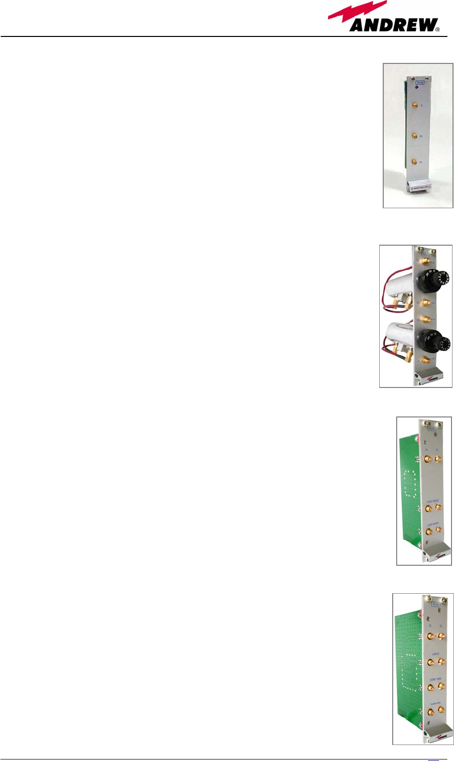
2.2. The Britecell Plus Remote Unit
and its relevant accessories
The Remote Unit (TFAx) is a device providing optical-to-electrical downlink
conversion and electrical-to-optical uplink conversion, thus allowing a
bidirectional transmission of signals between the Master Unit and the remote
antennas. It is available in 3 different power configurations
(Low/Medium/High), housed by 4 different architectures (Case A, Case B, Case
F and Case L), so as to fulfil different coverage and band requirements.
In downlink, each TFAx receives an optical signal from the Master Unit,
performs an optical-to-RF conversion, and transmits the resulting signal to the
2 antenna ports.
In uplink, it receives a RF signal from remote antennas, provides a RF-to-
optical conversion, and conveys the converted signal to the Master Unit
through optical fibres.
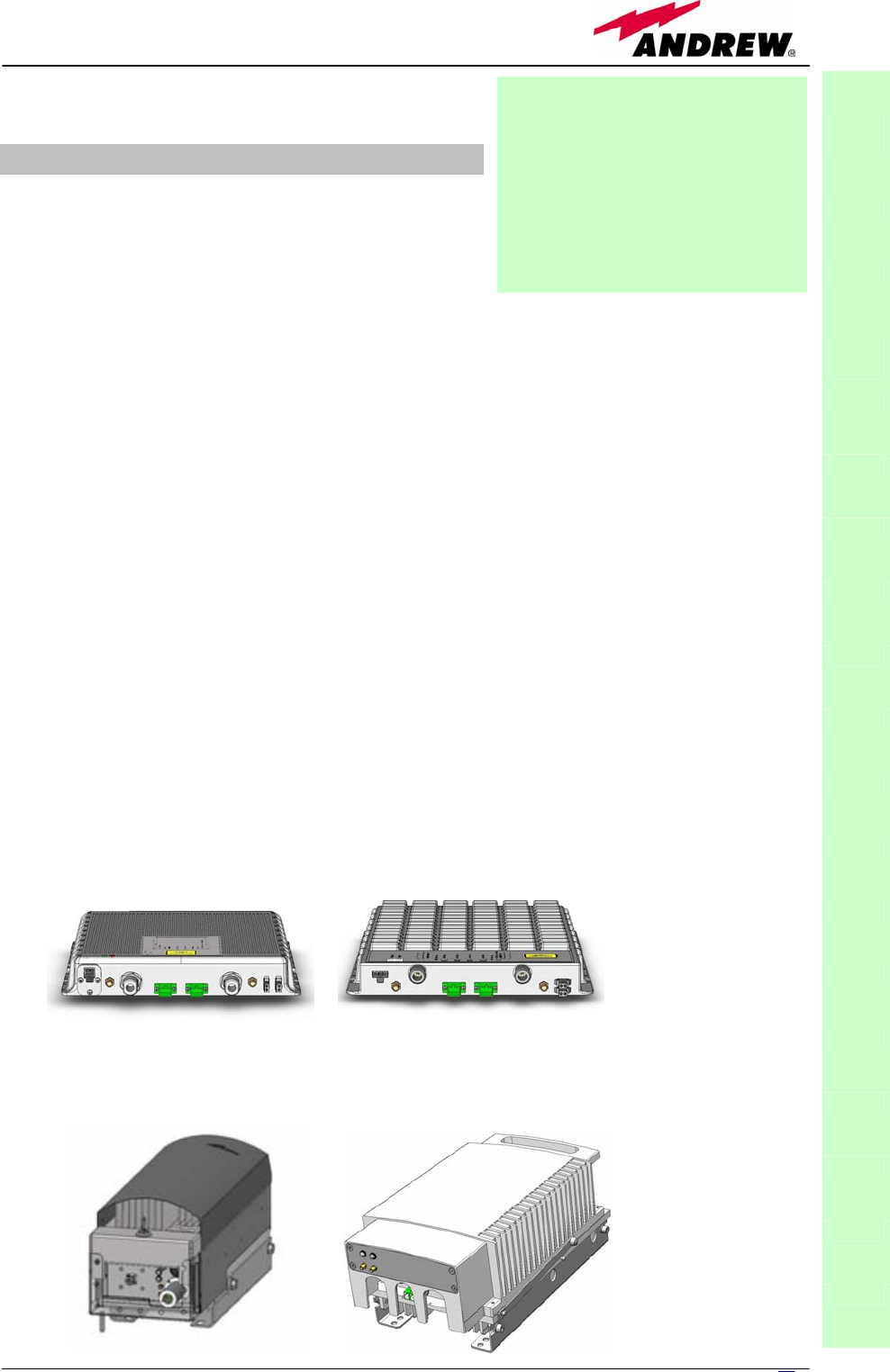
Case-A
Case-B
Case-L
Case-F
Fig.2.1: Different Remote Unit cases
Power supply (available either in 90÷264 Vac or in -72÷-36 Vdc version) is
internal in Case L, in Case F and in most Case A remote units: vice-versa, all
Case B and some Case A remote units are provided with an external power
supply (TPSN), whose dimensions are shown in table 2.1(a).
The TFBW unit is a booster which can be cascaded with a TFAx in order to
distribute Wi-Fi signals (802.11b and g) through dedicated Wi-Fi antennas
(see scheme 2.2b).
Fig. 2.2 (a) TFBW booster ; (b) block
diagram of a Britecell Plus system with Wi-Fi
Interface
(a)
Remote
Unit Wi-Fi
booster
BTS Master Unit
with
Wi-Fi interface
Access
Point
(b)
The case-A and Case-B Remote Units and the TFBW boosters can be provided
with the TKA installation kit (optional), which contains a fiber optics splice
holder and a compact case, in order to allow an easy installation on walls or
poles. TKA compact cases allow different IP protection levels, depending on
the specific environmental requirements.
Fig. 2.3: TKA mounting kit for Case A and Case B remote units
11
MN024-08
12 User Manual
2.3. The Britecell Plus Master Unit
The Britecell Plus Master Unit is a widely-flexible system. It is available both as
a stand-alone version (the Fast Master Unit) and as a rack-based version. In
the followings we will give a brief overview of the components of these units.
The Master Fast (TFLF): designed into a
stand-alone mechanical case, it includes all
required ancillary and support functions. It is available
in various frequency ranges, from 800MHz up to 2200MHz
and allows feeding up to 4 Remote Units.
Module dimensions: 240 x 200 x 38mm
The Sub-rack (TPRN) is a 19” subrack hosting the Britecell Plus modules; it
accommodates 12 slots, whose sizes are 7TE x 4HE. As each Britecell Plus
module takes up one or two slots, each Master Unit can sustain up to 12
modules, depending on design configuration and requirements.
The Master Optical TRX (TFLN): in downlink it provides
an RF-to-optical conversion of the signal coming from the
BTS, and transmits it to 4 optical outputs, so as to feed 4
TFAx. In uplink it provides optical-to-RF conversion for 4
optical signals coming from RUs, and it combines them into a
single RF output, while providing automatic gain control in
order to balance the fibre losses. Module dimensions:
Width = 7TE, Height = 4HE (one slot in the master unit sub-
rack).
2.3.1 The Fast Master Unit
2.3.2 The rack-based Master Unit
Fig. 2.4: The Fast Master Unit
Fig. 2.5: The TPRN Subrack
Fig. 2.6:
The TFLN Master Optical TRX
13
MN024-08
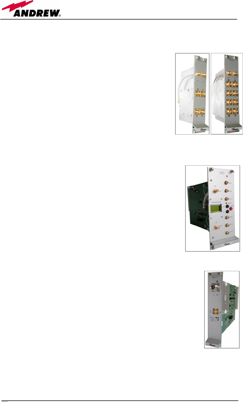
The duplexer (TDPX): it combines the downlink (DL) and uplink
(UL) paths into a single one, while maintaining the required
isolation. The module dimensions are: Width = 7TE, Height = 4HE.
The variable RF attenuators (TBSI): it provide independent
attenuations (adjustable from 0 to 30dB, with 1dB steps) on
uplink and downlink RF paths, and allow the designer to optimize
the signal level close to the BTSs. TBSI is an override attenuator,
its dimensions are: Width = 7TE, Height = 4HE.
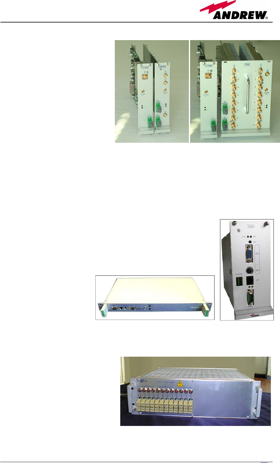
The dual band coupler (TLDN): in downlink it combines a low
band RF signal (800 to 1000 MHz) and a high band RF signal (1700
to 2500 MHz) into a common RF port; in uplink it splits a composite
signal between a low band RF port and a high band RF port. Module
dimensions are: Width = 7 TE, Height = 4 HE.
The tri band coupler (TLTN): in downlink it combines the low
band signals (800 or 900MHz), the 1800MHz band signal and
2000MHz signal into a common one; in uplink it splits the triple
band signal between three different RF single band paths. Module
dimensions are: Width = 7 TE, Height = 4 HE.
Fig. 2.7:
The TDPX duplexer
Fig. 2.8:
The TBSI variable attenuator
Fig. 2.9:
The TLDN tri- band coupler
Fig. 2.10:
The TLTN tri-band coupler
14 User Manual
The RF splitters/combiners (TLCN2 and TLCN4): TLCN2 is a 2-way
splitter/combiner. TLCN4 is a 4-way splitter/combiner. They can be used in a
variety of different situations, such as:
• To connect a BTS with several master optical TRXs.
In uplink the TLCN2 (or TLCN4) combines 2 (4) RF
signals coming from different master optical TRXs
onto a common RF signal, entering the BTS. In
downlink the TLCN2 (or TLCN4) splits the downlink
composite RF signal coming from the BTS onto 2 (4)
RF ports, entering different master optical TRXs;
• To connect several BTSs to a master optical TRX. In
downlink the TLCN2 (TLCN4) combines the RF signals
coming from different BTSs onto a common RF
signal, entering the master optical TRX. In uplink
TLCN2 (TLCN4) splits the composite RF signal coming
from a master optical TRX into 2 (4) RF signals
entering different BTSs.
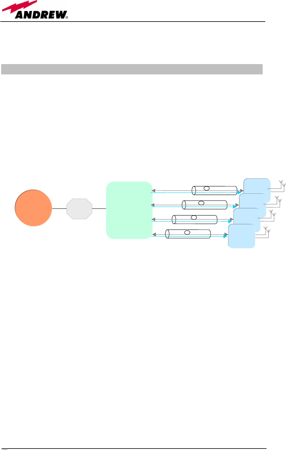
The WLAN interface board (TWLI):.it connects 3 WLAN
Access Points to each TFLN, and it is necessary when
802.11b/g WLAN distribution through the DAS is required.
Dimensions: Width = 14 TE, Height = 4HE (2 slots in the
master unit sub-rack).
The power limiter (TMPx-10): it monitors the DL power coming
from the BTS, and attenuates it by 10 dB in case of overcoming of
a programmable threshold level.
TMP2-10 Power Limiter is for 2G and 2.5G signals, working at 900
MHz and 1800 MHz.
TMP3-10 Power Limiter is for 3G signals.
Both modules are 7TE wide and 4HE high.
Fig. 2.11: The TLCN2 and
TLCN4 splitters/combiners
Fig. 2.12:
The TWLI Wi-Fi interface board
Fig. 2.13:
The TMPx-10 power limiter
15
MN024-08
The interconnect-link (TILx)
is a multi-module kit which
allows to expand our system
by connecting an additional
Britecell Plus subrack station to
the main one, at a distance of
up to 20 km. In details:
• The TDTX and TMRX cards
make up the “master side” of
the i-link; thus, they have to
be housed inside the main
Britecell Plus subrack, and
take 1 slot each;
• The TDTX and TSRX cards
make up the “slave side” of
the i-link; thus, they have to be housed inside the remotised Britecell Plus
subrack, and take 1 slot and 3 slots respectively.
The TILx kit is available either in simple (TILx-HL) or in WDM (TILx-HLW)
version.
The remote supervision unit (TSUN): it is able to control
up to 14 master units fully populated. It is available both as a
plug-in module (Width = 14 TE, Height = 4HE, 2 slots in the
master unit sub-rack) and as stand alone device (Width= 19”,
Height=1HE). It consists in a CPU, a flash memory and an
Interface Board
The Remote Power Unit
(TRS/TRSN): it is a sub-rack unit
(whose sizes are 7TE x 4HE)
providing remote power supply to
up to 24 remote units through
standard AWG14/16 copper lines.
It is available in 2 versions:
• The TRSN version is able to
supply 1 A per port and it can
feed all remote units.
• The TRS version is able to
Fig. 2.14: The TILx interconnect link (i-link)
Fig. 2.15: The TSUN remote supervision unit
Fig. 2.16: The TRSN subrack
16 User Manual
supply 0.5A per port: it can feed only single and dual band TFAN remote
units, as well as the TFAM20 one.
2.4. Block diagrams
In order to better understand the functionalities of the different units and
modules, some block diagrams of the Britecell Plus system are reported
hereafter.
Systems based on Fast Master Unit must be directly connected to the BTS
station. The scheme of a typical Fast Britecell system is reported here in fig.
2.17.
Fig. 2.17: Block diagram for a Fast system
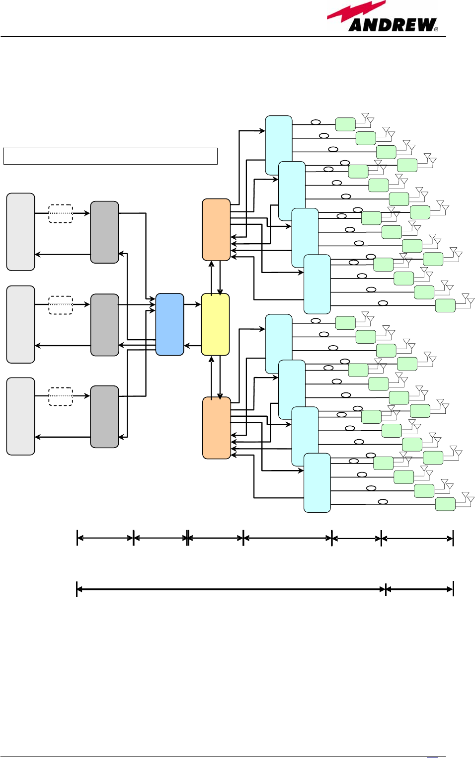
A more complex distribution system requires a rack-based Master Unit. It
allows the employment of a splitting/combining section (built by some passive
modules TLTN, TLDN, TLCN, and TBSI described above) in order to interface
one or more BTSs with several TFLN optical TRXs and with an higher number
of TFAx remote units.
Firstly, let’s assume that our BTSs are not duplexed. In this case, no TDPX
module (see fig. 2.7) is required. Moreover, let’s assume that the Master Unit
is made up of one or more subracks located in a single site, so that we do not
need an interconnect link in order to remotise a second subrack.
The scheme of this network configuration is reported hereafter in figure 2.18.
B
T
S TFLF
Mixed fibre-copper cable
Mixed fibre-copper cable
Mixed fibre-copper cable
Mixed fibre-copper cable
Fixed
Attenuator
TFAx
TFAx
TFAx
TFAx
17
MN024-08
Fig. 2.18: Block diagram for a triple-band system with not-duplexed base stations.
This scheme involves a rack-based Master Unit, with 8-TFLN optical TRXs and 32 TFAx
remote units.
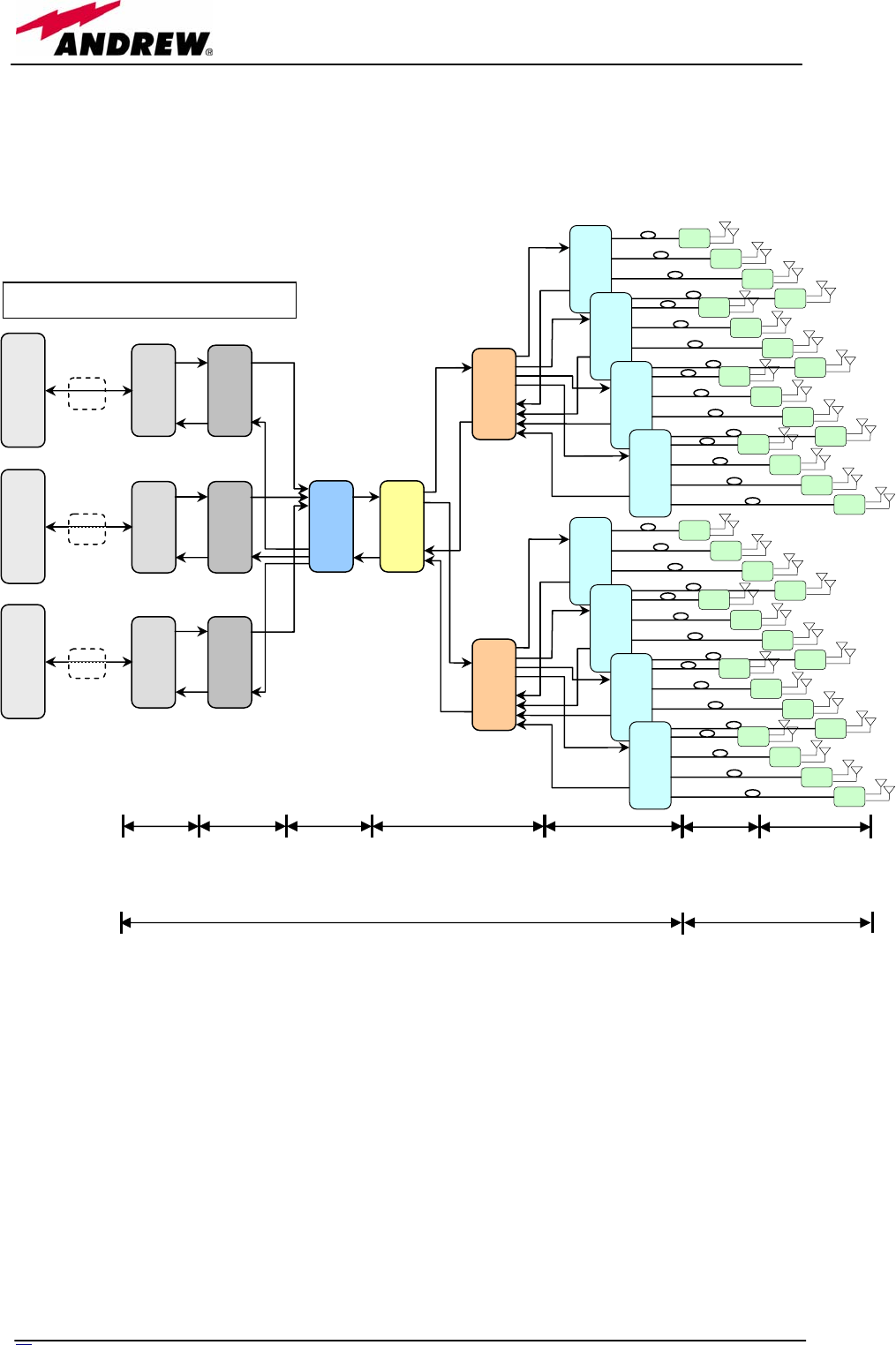
Now let’s consider the same network configuration, but with duplexed BTSs. In
this case, some TDPX modules (see fig. 2.7) are required in order to combine
UL and DL ports on single RF channels. .
Level
adjustment
Services
combining /
splitting
Signal splitting /
combining
Electrical / optical
conversion
Optical / electrical
conversion
Triple
-
band system
–
not duplexed BTSs
–
8 TFLN local units
TLCN2
TLTN
TBSI
TBSI
TBSI
GSM
900
BTS
GSM
1800
BTS
UMTS
BTS
Fixed
Atten.
Fixed
Atten.
Fixed
Atten.
TLCN4
TFLN
TFAx
TFAx
TFAx
TFAx
TFLN
TFAx
TFAx
TFAx
TFAx
TFLN
TFAx
TFAx
TFAx
TFAx
TFLN
TFAx
TFAx
TFAx
TFAx
TFLN
TFAx
TFAx
TFAx
TFAx
TFLN
TFAx
TFAx
TFAx
TFAx
TFLN
TFAx
TFAx
TFAx
TFAx
TFLN
TFAx
TFAx
TFAx
TFAx
TLCN4
-
Britecell Plus MASTER UNIT Britecell Plus
REMOTE UNITS
18 User Manual
The scheme of this network configuration is reported hereafter in figure 2.19.
Fig. 2.19: Block diagram for a triple-band system with duplexed base stations. This
scheme involves a rack-based Master Unit, with 8-TFLN optical TRXs and 32 TFAx
remote units.
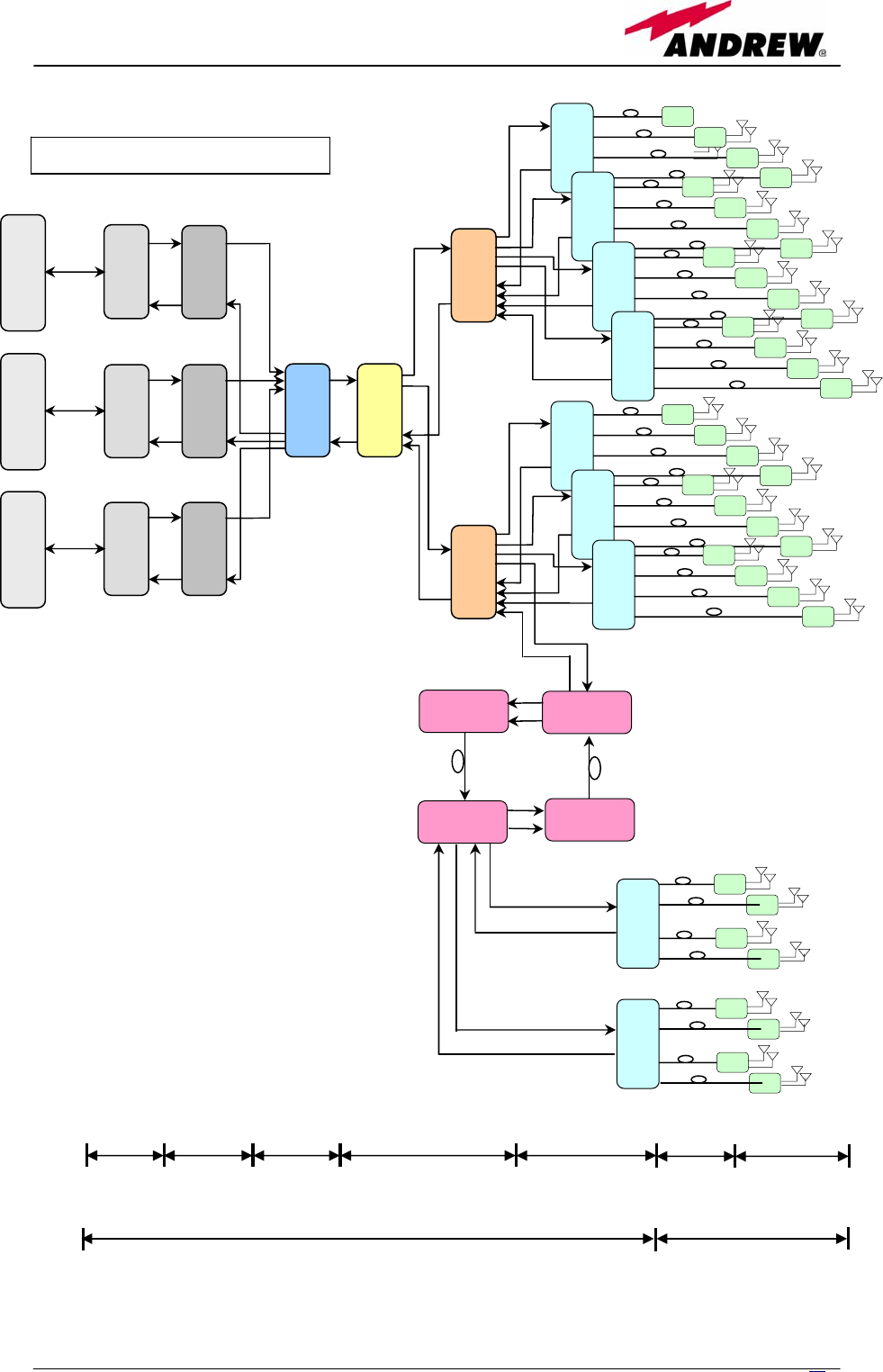
Let’s assume we need to expand our network in a wider area, by using a
second subrack station at a distance of up to 20 km from the site where the
main subrack station is located.
This new network configuration requires to use an interconnect link, whose
master side will be at the main subrack station, and whose slave side will be at
the new remotised station.
The scheme of this new network topology is shown hereafter, in figure2.20.
TLCN2
TLTN
TBSI
TBSI
TBSI
TDPX
91
TDPX
20
TDPX
18
GSM
900
BTS
GSM
1800
BTS
UMTS
BTS
DL - UL
splitting /
combining
Level
adjustment
Services
combining /
splitting
Signal splitting /
combining Electrical / optical
conversion Optical/electrical
conversion
3 km max
optical link
Triple-band system – duplexed BTSs – 8 TFLN
Fixed
Atten.
Fixed
Atten.
Fixed
Atten.
TLCN4
TFLN
TFAx
TFLN
TFLN
TFLN
TFLN
TFLN
TFLN
TFLN
TLCN4
TFAx
TFAx
TFAx
TFAx
TFAx
TFAx
TFAx
TFAx
TFAx
TFAx
TFAx
TFAx
TFAx
TFAx
TFAx
TFAx
TFAx
TFAx
TFAx
TFAx
TFAx
TFAx
TFAx
TFAx
TFAx
TFAx
TFAx
TFAx
TFAx
TFAx
TFAx
Britecell Plus MASTER UNIT Britecell Plus
REMOTE UNITS
19
MN024-08
DL - UL
splitting /
combining
Level
adjustment
Services
combining /
splitting
Signal splitting /
combining Electrical / optical
conversion Optical/electrical
conversion
3 km max
optical link
Britecell Plus MASTER UNIT Britecell Plus
REMOTE UNITS
TLCN2
TLTN
TBSI
TBSI
TBSI
TDPX
91
TDPX
20
TDPX
18
GSM
900
BTS
GSM
1800
BTS
UMTS
BTS
Triple-band system – duplexed BTSs – i-link
TLCN4
TFLN
TFAx
TFLN
TFLN
TFLN
TFLN
TFLN
TFLN
TLCN4
TFAx
TFAx
TFAx
TFAx
TFAx
TFAx
TFAx
TFAx
TFAx
TFAx
TFAx
TFAx
TFAx
TFAx
TFAx
TFAx
TFAx
TFAx
TFAx
TFAx
TFAx
TFAx
TFAx
TFAx
TFAx
TFAx
TFAx
TD
T
X
TMRX
TFAx
TFAx
TFAx
TFAx
TFLN
TFAx
TFAx
TFAx
TFAx
TFLN
TSRX
TD
T
X
Fig. 2.20: Block diagram for a
Britecell system with
remotised station connected
through i-link. This scheme
refers to a triple-band system
with duplexed base stations.
It involves 7 TFLN optical
TRXs and 28 TFAx remote
units on the master side, 2
TFLN optical TRXs and 8 TFAx
on the slave side .
Lastly, the next tables show a brief overview of the available Britecell
equipment:
REMOTE UNITS and accessories
Unit name/
Module name
Description Dimensions (L x W x H)
TFAx case A
TFAx case B
TFAx case L
TFAx case F
TFBWx
TKA01
TKA04
TPSN 1-40
TPSN 3-30
Remote unit
Remote unit
Remote unit
Remote unit
WLAN booster
Remote Unit installation kit
Remote Unit installation kit
External power supply
External power supply
240 x 200 x 38 (mm)
240 x 240 x 38 (mm)
455 x 255 x 167 (mm)
546 x 253 x 207 (mm)
240 x 200 x 38 (mm)
280 x 240 x 55 (mm)
340 x 240 x 55 (mm)
175 x 80 x 54 (mm)
175 x 80 x 51 (mm)
Table 2.1(a): Overview of the Britecell Plus remote units and accessories
FAST MASTER UNIT
Unit name/
Module name Description Dimensions (L x W x H)
TFAF
Fast Master Unit
240 x 200 x 38 (cm)
Table 2.1(b): Britecell Plus fast master unit
20 User Manual

21
MN024-08
Table 2.1(c): Overview of the Britecell Plus components and accessories
for the rack-based master unit
RACK-BASED MASTER UNIT
Unit name/
Module name Description Dimensions (L x W x H)
TPRN04
TPRNx4
TFLNx
TLCN 2
TLCN 4
TBSI 2-30
TDPXx
TLDNx
TLTNx
TMPx-10
TWLI
TILx-HL
TILx-HLW
TSUN6
TSUN1 or TSUN3
TRS/TRSN
Passive subrack
Active subrack
Master Optical TRX
2-way splitter
4-way splitter
Adjustable attenuator
UL/DL duplexer
Dual band coupler
Tri band coupler
10 dB power limiter
WLAN interface
i-link kit
WDM i-link kit
Remote supervision unit standalone
Remote supervision unit plug in
Remote supply unit
19” x 4HE
19” x 4HE
7TE x 4HE
7TE x 4HE
7TE x 4HE
7TE x 4HE
7TE x 4HE
7TE x 4HE
7TE x 4HE
7TE x 4HE
14TE x 4HE
14TE x 4HE (master side) +
28TE x 4HE (slave side)
14TE x 4HE (master side) +
28TE x 4HE (slave side)
19” x 4HE
14TE x 4HE
19” x 1HE

22 User Manual
3. TFAx Remote Unit
TFAx
(intro)
23
MN024-08
3.1. Introduction
Main tasks of the TFAx unit:
Downlink (DL):
¾ Optical-to-RF conversion of the input optical
signal
¾ Automatic Gain Control (AGC) of each converted signal, in order to
compensate optical losses;
¾ RF amplification: the converted RF signal is boosted in order to maintain a
good signal-to-noise ratio
¾ RF filtering: a proper filter rejects the spurious emissions
¾ RF duplexing and splitting: the boosted RF signal is conveyed to 2 antenna
ports
Uplink (UL):
¾ RF amplification: a low noise amplifier boosts the signal received from
antennas so as to maintain a good signal-to-noise ratio
¾ RF filtering: the boosted signal is cleaned from the spurious emissions
¾ Automatic Level Control (ALC): the RF signal level is adjusted according to
blocking requirements
¾ RF-to-optical conversion of the signal, which is finally conveyed to the
output optical port
Different types of Case-A remote units
In order to allow radio coverages with different power and band requirements,
Britecell architecture provides a wide variety of remote units. This allows the
customer to choose the solution which best fits its coverage and
environmental demands.
TFAx
(intro)
Figure 3.1: The
four different
case of the
Britecell Plus
remote unit
Module name:
Remote Unit
TFAx
(TFAN,TFAM,TFAH)
Case B remote unit
Case A remote unit
Case L remote unit Case F remote unit
24 User Manual
Depending on the bands where the radio coverage has to be provided and on
the required signal power to cover the environment, your remote unit can
have one of the topologies shown in figure 3.1.
The following 4 sections of the manual refers to these 4 different topologies of
remote units. Please follow the instructions described in the section which
exactly corresponds to the case (A,B,L,F) of your remote unit.
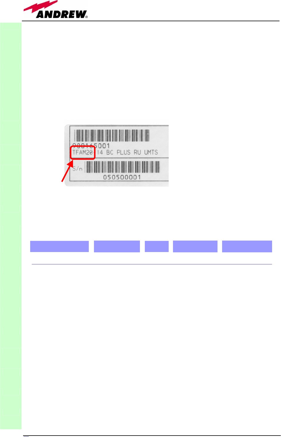
The output powers and coverage bands of each remote unit are uniquely
associated to model codes which you can easily read on both on the remote
unit and on its package box (see picture 3.2 below).
The case of your remote unit can be easily identified from the pictures 3.1: as
an alternative, you can refer to the Britecell Plus Bulletin PA-100595EN or to
the dedicated Bulletin of your remote unit. For example, let’s refer to the
Model Number “TFAM20” we read on our remote unit’s label, like in the
Ficture 3.2. On the Britecell Plus bulletin PA-100595EN, we read:
This line states that the remote unit whose model is TFAM20 has a case A
architecture (see picture 3.1), manages UMTS (2100 MHz) signals, and works
with Medium output powers. Once we identified the case of our remote unit
(case A, in this example), let’s refer to this manual’s section which exactly
corresponds to our remote unit case, so as to perform proper installation and
maintenance procedures.
Each Britecell Plus remote unit belongs to one of the following 3 power
classes: Low, Medium and High Power. Once we know the Power Class of our
remote unit (Medium, in our example), and its working bands (e.g. 2100 MHz
UMTS), we can look through the remote unit dedicated bulletin (described
under the column “Details in bulletin”: PA-100592EN, in our example) in
order to get all the technical specifications concerning the remote unit itself.
TFAx
(Intro)
Figure 3.2
Figure 3.3
Band Configurations Power Class Case Model Code
UMTS2100 Medium A TFAM20 PA-100592EN
Details in Bulletin
25
MN024-08
3.2. Case A remote unit
Dimensions and Weight:
Dimensions: 38 x 240 x 200 mm
(1.5 x 9.4 x 7.9 inches)
Weight : please refer to the Britecell Plus bulletin PA-100595EN or to the
remote unit dedicated bulletin in order to know the updated data
about the weight of your case A remote unit
An external power supply is provided only for Case A remote unit TFAM20.
TFAx
CaseA
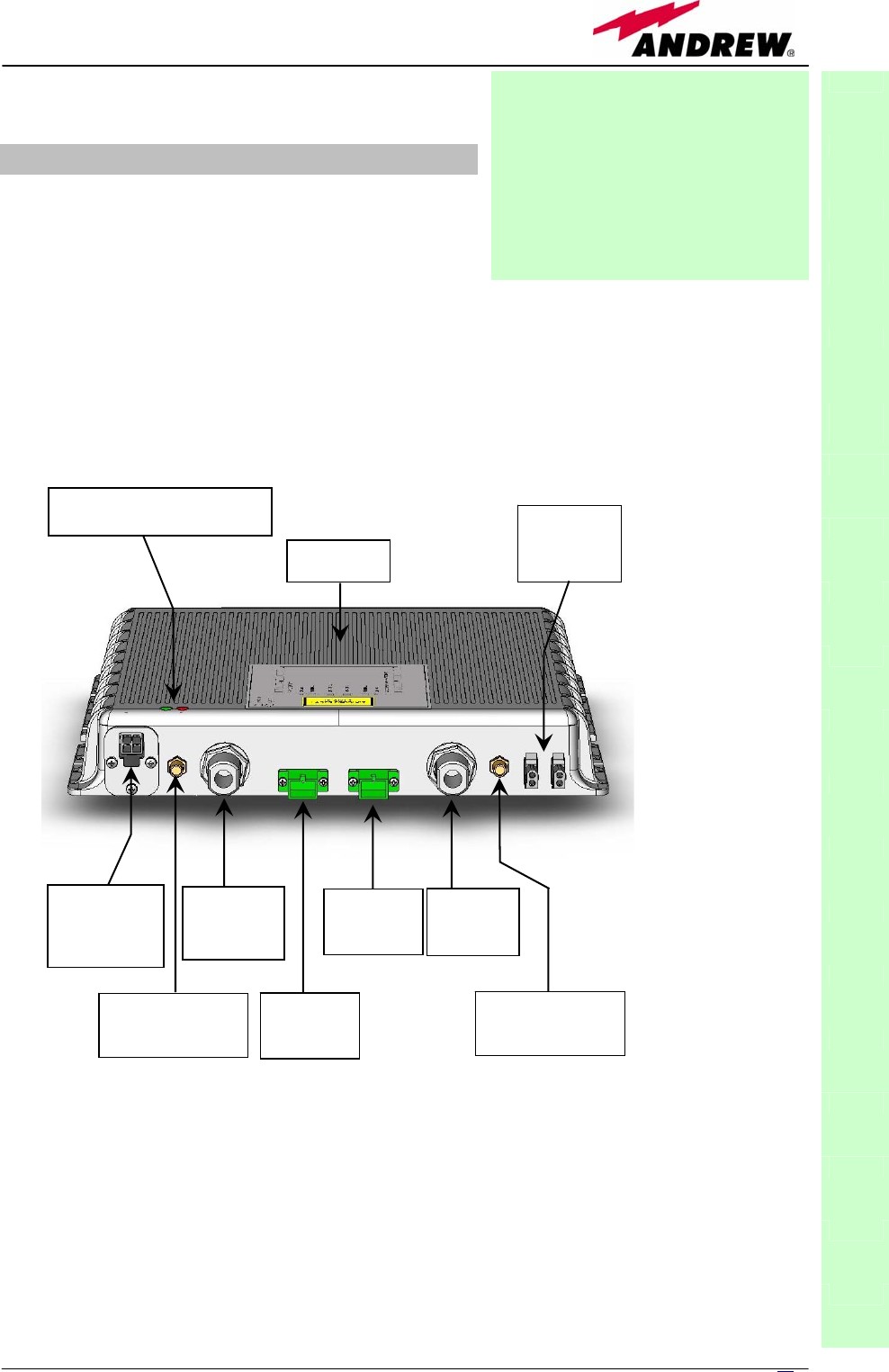
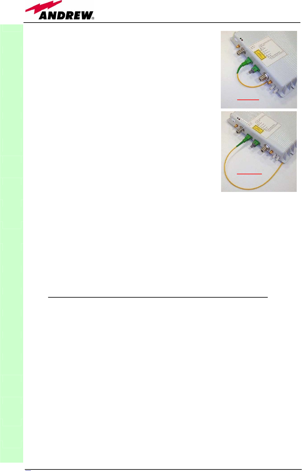
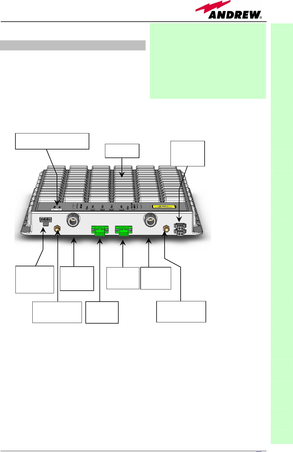
RF ports:
• 2 RF antenna ports, transmitting/receiving signals to/from
distributed antennas. RF antenna ports are duplexed N-female
connectors. These RF ports can be connected to the antennas
either directly (ie. through RF jumper cables) or through
splitters, thus allowing more antennas to be fed. Unused RF
ports have to be terminated with a 50 Ω load.
• 1 RF auxiliary input and 1 auxiliary output (designed to
receive and transmit additional signals). Auxiliary input and
output ports are SMA-female connectors.
Power
Supply
connector
DL optical
port
(SC-APC)
External
alarm
connectors
Warm side
RF
antenna
port (N-f)
Green LED = power on
Red LED = major alarm
RF auxiliary
channel output
(
SMA-f
)
UL optical
port
(SC-APC)
RF
antenna
port (N-f)
RF auxiliary
channel input
(
SMA-f
)
Module name:
Remote Unit
TFAx
Case A
Fig. 3.4: 3D-drawing of
a Case A remote unit
26 User Manual
Optical ports:
Visual alarms:
Two control LEDs are provided on the TFAx front side (see fog. 3.19). The
green LED describes the power supply status, while the red LED describes the
major Remote Unit failures (please refer to the table 3.1).
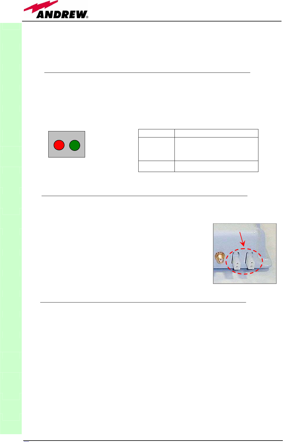
External alarms:
TFAx is provided with two dry contacts inputs, which
can be connected (through .062” MOLEX plugs) to any
external device. In such a way, the alarm information
about this external device can be signalled through the
red LED of TFAx LED panel and displayed into the
supervision system.
Power supply
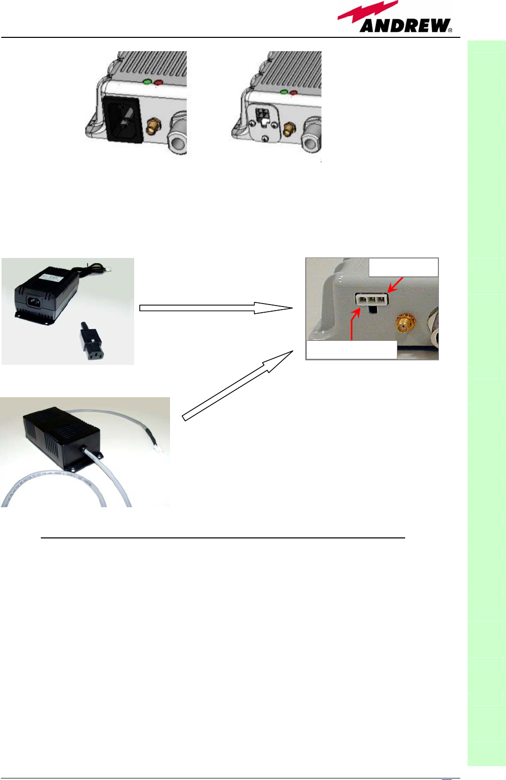
Case A remote units can be powered by universal mains (90 to 264 Vac) or
by negative supply (-72 to -36 Vdc). Power supply is internal for all Case A
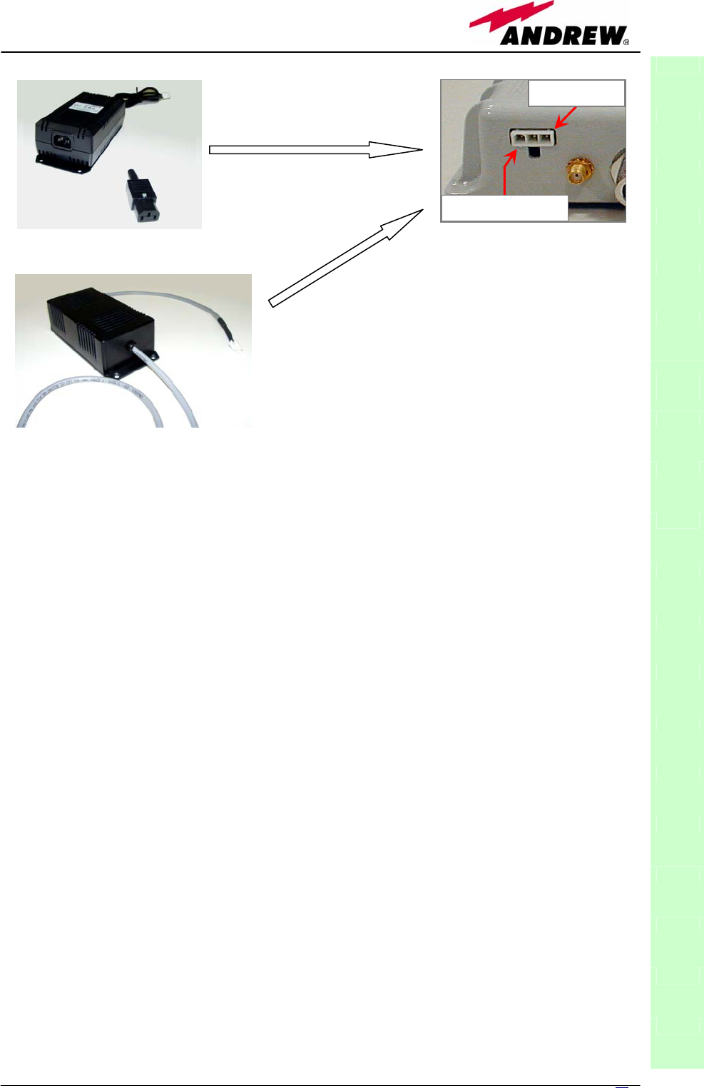
remote units, except for TFAM20 which has an external adapter.
Fig. 3.9a,b shows the different power supply connectors which are provided
on 90/264 Vac and on -72/-36 Vdc versions (except TFAM20).
TFAM20 remote unit is provided with the TPSN external power supply (fig. 3.8
a,b), available either for universal mains (90 to 264) or for negative supply.
(-72 to -36 Vdc). They both provide the remote units with a +5Vdc power, by
means of a 3-pole connector (fig. 3.10c).
Led colour Meaning
Red
Low optical power at DL
input and/or RF
amplifier failure
Green Power supply OK
TFAx
CaseA
dr
y
contacts
• 1 optical output port, transmitting UL signals to
TFLN master optical TRX
• 1 optical input port, receiving DL signals from TFLN
master optical TRX
Table 3.1: summary of TFAx LEDs meaning
Fig. 3.5 : LED panel on
the Case-A warm side
Fig. 3.6 : Dry-contacts
on Case A back side
27
MN024-08
Warnings (to be read before the remote units are
installed)
Dealing with optical output ports
The TFAx remote unit contains semiconductor lasers. Invisible laser beams
may be emitted from the optical output ports. Do not look towards the optical
ports while equipment is switched on.
Choosing a proper installation site for the remote units
• TFAx remote units have to be installed as close as possible to the radiating
antennas, in order to minimize coaxial cable length, thus reducing downlink
power loss and uplink noise figure.
TFAx
CaseA
Fig. 3.7 : (a) IEC connector on the rear side of a 220Vac-powered case A remote unit. (b)
4-pole connector on the rear side of a -48 Vdc -powered case A remote unit. These
connectors are not available on TFAM20, which is provided with an external adapter
(see below).
(b)
(a)
Ground
Positive +5 Vdc
(a)
Fig. 3.8 : TPSN external adapters for 220
Vac (a) and -48 Vdc (b) TFAM20
versions. Power supply connector on the
rear side of TFAM20 remote unit (c).
(c)
(b)
28 User Manual
• When positioning the TFAx remote unit, pay
attention that the placing of related antennas
should be decided in order to minimize the
Minimum Coupling Loss (MLC), so as to avoid
blocking.
• The TFAx remote unit is intended to be fixed on
walls, false ceilings or other flat vertical surfaces
(TKA installation kits are available, in order to
provide a protective cover for TFAx remote unit,
while making the TFAx installation easier and
faster).
Handling optical connections
• When inserting an optical connector, take care to
handle it so smoothly that the optical fibre is not
damaged. Optical fibres are to be single-mode
(SM) 9.5/125µm.
• Typically, Britecell Plus equipment is provided with
SC-APC optical connectors (other connectors may
be provided on request). Inserting any other
connectors will result in severe damages.
• Do not force or stretch the fibre pigtail with radius
of curvature less than 5cm. See rightward figure
for optimal fibre cabling.
• Remove the adapter caps only just before making connections. Do not
leave any SC-APC adapter open, as they attract dirt. Unused optical
connectors must always be covered with their caps.
• Do not touch the connector tip. Clean it with a proper tissue before
inserting each connector into the sleeve. In case connector tips need to be
cleaned, use pure ethyl alcohol.
TFAx Case A installation
Versions with internal power supply
(all Case A remote units, except TFAM20)
Case A remote units can be fixed on walls, false ceilings or other flat vertical
surfaces, either directly or through a TKA01 installation kit (optional).
Installing a Case A remote unit (except TFAM20) WITHOUT the TKA
kit
The TFAx kit includes:
TFAx
CaseA
A. 1 remote unit TFAx
B. a 50 Ω load
C. a VDE connector or a -48 Vdc plug (according to
the chosen model)
Fig. 3.9: Improper (a)
and optimal (b) radius
bending for a fiber optics
cable.
OPTIMAL
(
b
)
WRONG
(
a
)
29
MN024-08
Remote units are provided with cooling fins which allow to optimize heat
dissipation. In order to let them work, the environment where the remote unit
is mounted should allow the necessary air changeover. Do not place any
remote unit face downwards on a horizontal surface, because this would
prevent heat dissipation.
Once you have chosen the position of the remote unit, please follow these
steps in order to carry out the installation:
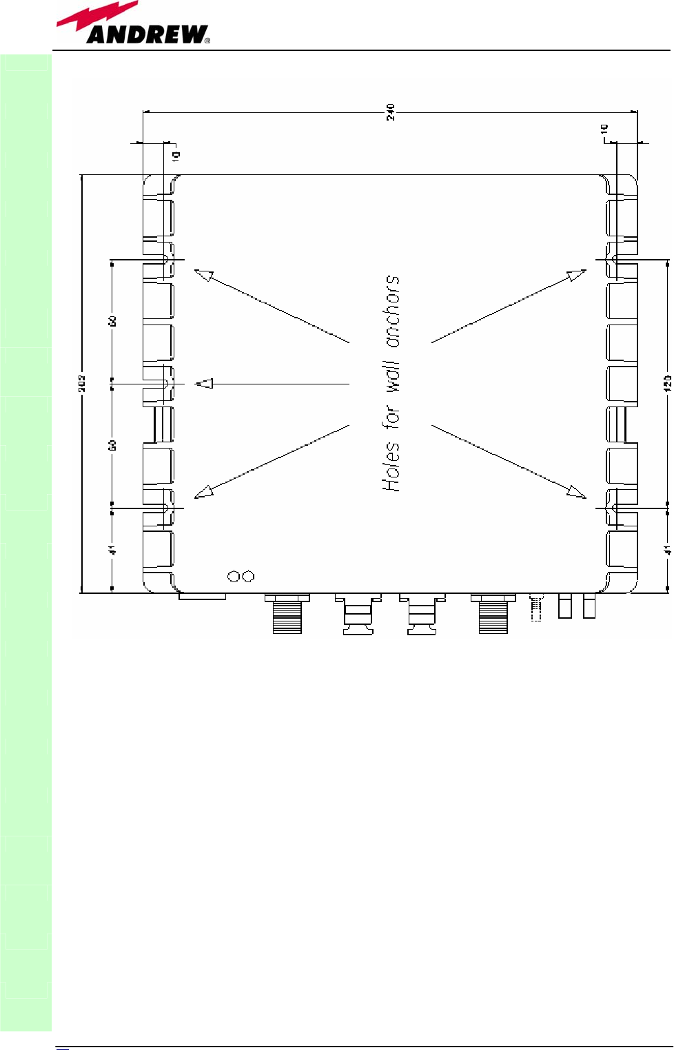
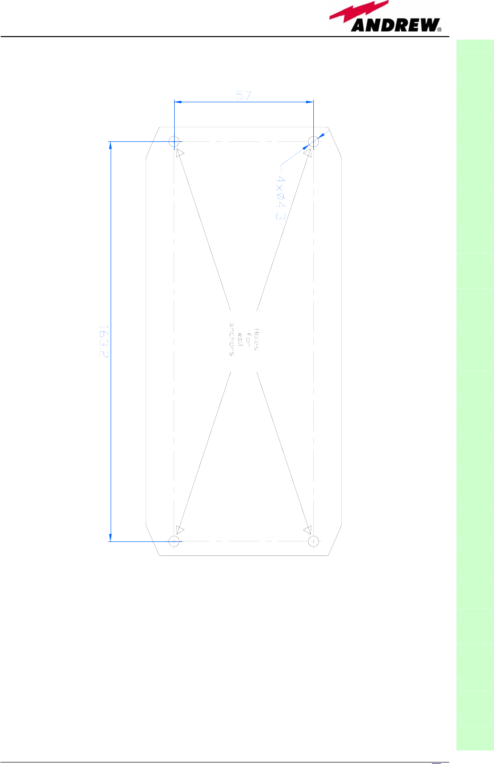
1. Drill into the wall so as to install the M4 screw anchors (not included)
according to the case A or case B layouts indicated by the installation
drawings in fig.3.15 (a)
2. Fix the TFAx remote unit to the wall by firmly screwing the anchors.
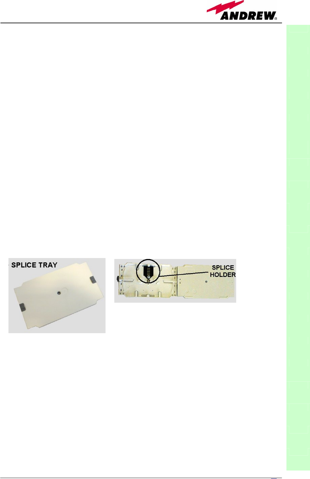
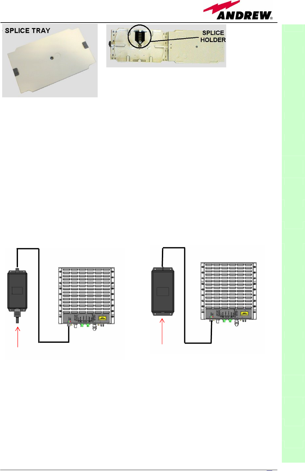
3. Take the splice – tray (not included). Fix the splice holder inside the splice
tray. (see fig. 3.10a,b)
4. Splice the optical fibres and close the splice tray. While handling the fibers,
take care of the fiber bending.
5. Fix the splice tray beside the remote unit
6. If the remote unit is -48 Vdc powered, use the -48 Vdc plug (included) in
order to connect the unit to the -48 Vdc mains. If the remote unit is
85/264 Vac-powered, fix the 85/264 Vac plug (included) on to a power cord
(not included), and use this cable in order to connect the unit to the mains.
7. Connect the antenna RF cables to the RF antenna ports. Connect the UL and
DL optical connectors (please refer to fig. 3.4). Apply a 50-Ohm load to the
RF which are no connected to any antenna cable.
8. Once the installation is finished, please follow the section “Start-up for case
A and case B remote units”, in order to carry out a proper system start up.
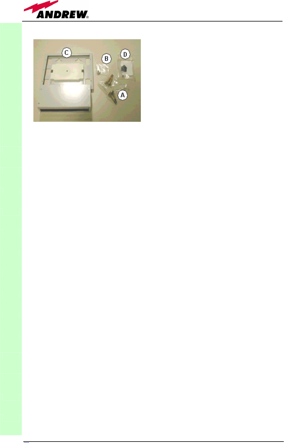
Installing the Case A remote unit (except TFAM20) WITH the TKA01
installation kit
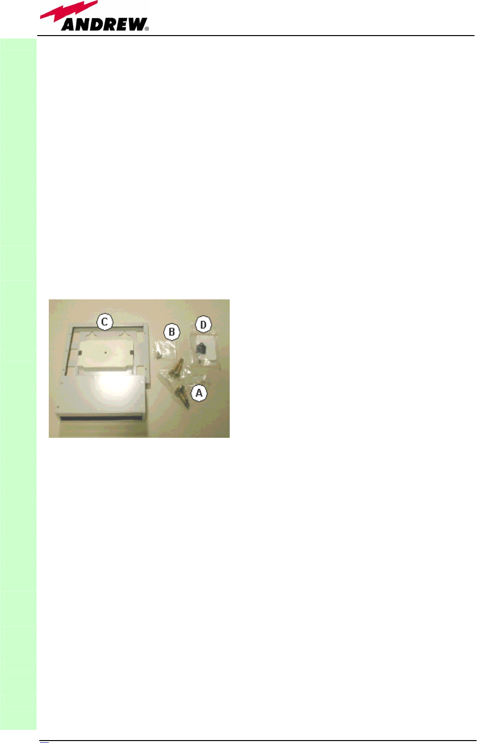
The TFAx kit includes:
The TKA01 kit includes:
(please refer to fig.
3.11)
TFAx
CaseA
(a)
(b)
Fig. 3.10. (a) Splice tray. (b) Inside of the splice tray,
with the splice holder properly positioned.
1. a remote unit TFAx
2. a 50 Ω load
3. a VDE connector or a -48 Vdc plug (according to
the chosen model)
A. 4 screw anchors (fixing the wall bearing to the
wall)
B. 5 screw anchors (fixing the TFAx case A to the
wall mounting box “C”)
C. A wall mounting boc
D. a splice holder
30 User Manual
Once you have chosen the position of the remote unit mounting case, please
follow these instructions:
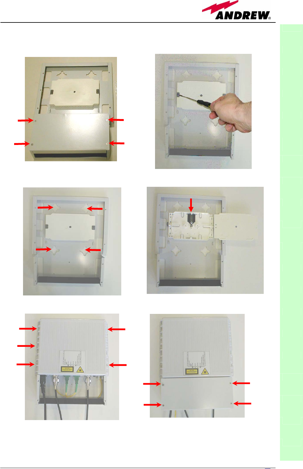
1. Unscrew the 4 screws which lock the lower cover of the TKA01 wall bearing
(see fig. 3.12a)
2. In order to install the M4 screw anchors (included) which shall hold up the
TKA01 wall bearing, drill into the wall according to the TKA layout shown in
fig. 3.15c.
3. Fix the TKA01 wall bearing by firmly screwing the anchors.
4. Carefully open the splice tray by using a screwdriver as in fig. 3.12b. Fix
the splice holder inside the splice tray. (see fig. 3.12c). Splice the optical
fibres and close the splice tray. While handling the fibers, take care of the
fiber bending. Close the splice tray.
5. Fix the remote unit to the wall bearing by using the included screws 3.12d.
6. If the remote unit is -48 Vdc powered, use the -48 Vdc plug (included) in
order to connect the unit to the -48 Vdc mains. If the remote unit is
85/264 Vac-powered, fix the 85/264 Vac plug (included) on to a power
cord (not included), and use this cable in order to connect the unit to the
mains.
7. Connect the antenna RF cables to the RF antenna ports. Connect the UL
and DL optical connectors (fig.3.12e). If the power cable has properly been
connected to the main, both the green and the red LEDs should turn on.
The green LED will remain on to indicate that the unit is powered on, while
the red LED will turn off as soon as the local unit will be switched on (for
further details about the start up of the system, please refer to the section
“TFAx Start-up”)
8. Fix the lower cover by fastening the 4 screws (fig.3.12f).
TFAM20 installation
TFAM20 remote unit can be fixed on walls, false ceilings or other flat vertical
surfaces, either directly or through a TKA01 installation kit (optional).
TFAx
CaseA
Fig. 3.11: The TKA01 installation kit

31
MN024-08
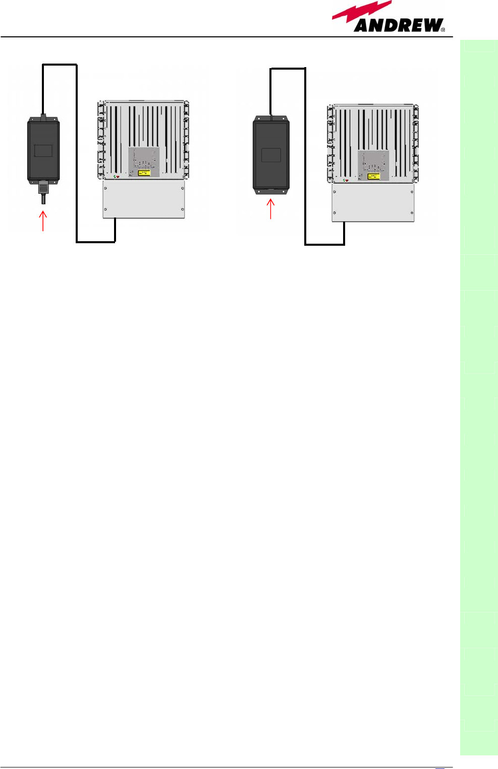
Installing a TFAM20 remote unit WITHOUT the TKA kit
The TFAM20 kit includes:
Please consider carefully these guidelines in order to choose a proper
positioning of the remote unit and of its power supply:
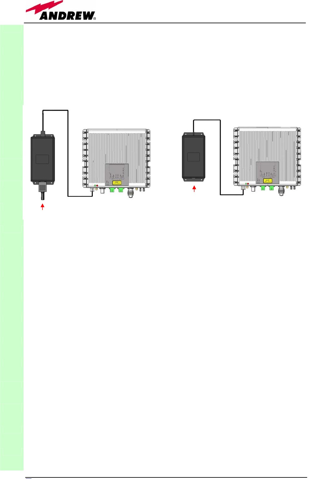
o Each piece of equipment should not be affected by the heating of any other
piece. The remote unit and its external power supply should be mounted so
as to avoid reciprocal heating. Side-by-side configuration is suggested (fig.
3.13 a,b)
o Remote units are provided with cooling fins which allow to optimize heat
dissipation. In order to let them work, the environment where the TFAM20
is mounted should allow the necessary air changeover.
o It is strongly recommended not to mount the external power supply on a
horizontal surface, because this position does not allow heat dissipation.
External power supplies must be mounted on vertical surfaces.
o In order to assure a proper heat dissipation, the external power supplies
must be mounted in vertical position with the power socket downwards (see
fig. 3.13a,b).
Once you have chosen the position of the remote unit, please follow these
instructions:
1. In order to install the M4 screw anchors (not included) which shall hold up
the TFAM20 remote unit, drill into the wall according to the case A layout
shown in fig. 3.15a.
2. Fix the TFAM20 to the wall by firmly screwing the anchors.
3. In order to install the M4 screw anchors (not included) which shall hold up
the power supply external adapter, drill into the wall according to the
power supply layout shown in fig.3.15b.
4. Fix the external power supply adapter to the wall by firmly screwing the
anchors.
5. Take the splice – tray (not included). Fix the splice holder inside the splice
tray. (see fig. 3.10a,b)
6. Splice the optical fibres and close the splice tray. While handling the fibers,
take care of the fiber bending.
7. Fix the splice tray beside the remote unit
8. Connect the external adapter to the TFAM20 remote unit through the
9. proper cable.
10. If the remote unit is -48 Vdc powered, use the -48 Vdc plug (included) in
order to connect the external adapter to the -48 Vdc mains (fig. 3.12b).
If the remote unit is 90/264 Vac-powered, fix the 90/264 Vac plug
TFAx
CaseA
1. a remote unit TFAM20
2. a 50 Ω load
3. a TPSN external power supply adapter (90 to
264 Vac or -72 to -36 Vdc, according to the
chosen model)
4. a VDE connector or a -48 Vdc plug (according to
the chosen model)
32 User Manual
(included) on to a power cord (not included), and use this cable in order
to the external adapter to the mains (fig. 3.12a).
11. Connect the antenna RF cables to the RF antenna ports. Connect the UL
and DL optical connectors.
12. Once the installation is finished, please follow the section “TFAx case A
remote unit”, in order to carry out a proper system start up.
Installation of the TFAM20 remote unit WITH the TKA01 installation
kit
The TFAM20 kit includes:
The TKA01 kit includes:
(please refer to fig.
3.11)
TFAx
CaseA
Fig. 3.12. Example of proper mounting configuration, which assures heat dissipation. Note that the
remote unit and its power supply adapter are mounted side-by-side, and the power supply adapter
has the socket downwards. The pictures refer to a 90/264 Vac – powered TFAM20 (a) and to a –
72/-36 Vdc –powered TFAM20 (b).
1. a remote unit TFAx
2. a 50 Ω load
3. an external power supply adapter (86 to 264 Vac
or -72 to -36 Vdc, according to the chosen
model)
4. a VDE connector or a -48 Vdc plug (according to
the chosen model)
A. 4 screw anchors (fixing the wall bearing to the
wall)
B. 5 screw anchors (fixing the TFAx case A to the
wall mounting box “C”)
C. A wall mounting boc
D. a splice holder
(a)
universal mains
(90 to 264Vac)
(b)
neg. supply
(
-
72 to
-
36Vdc
)
33
MN024-08
TFAx
CaseA
(a)
(c) (d)
(e) (f)
Fig. 3.13: Mounting the TFAx Case A with a TKA01
installation kit
(b)

34 User Manual
Please consider carefully these guidelines in order to choose a proper
positioning of the remote unit and of its power supply:
o Each piece of equipment should not be affected by the heating of any other
piece. The remote unit and its external power supply should be mounted so
as to avoid reciprocal heating. Side-by-side configuration is suggested (fig.
3.14 a,b)
o It is strongly recommended not to mount the external power supply on a
horizontal surface, because this position does not allow heat dissipation.
External power supplies must be mounted on vertical surfaces.
o In order to assure a proper heat dissipation, the external power supplies
must be mounted in vertical position with the power socket downwards
(see fig. 3.14a,b).
Once you have chosen the position of the remote unit mounting case, please
follow these instructions:
1. Unscrew the 4 screws which lock the lower cover of the TKA01 wall
bearing (see fig. 3.13a)
2. In order to install the M4 screw anchors (included) which shall hold up
the TKA01 wall bearing, drill into the wall according to the TKA layout
shown in fig. 3.15c.
3. Fix the TKA01 wall bearing by firmly screwing the anchors.
4. In order to install the M4 screw anchors (not included) which shall hold up
the power supply external adapter, drill into the wall according to the
power supply layout shown in fig.3.15b
5. Fix the external power supply adapter to the wall by firmly screwing the
anchors.
6. Carefully open the splice tray by using a screwdriver as in fig. 3.13b. Fix
the splice holder inside the splice tray. (see fig. 3.13c). Splice the optical
fibres and close the splice tray. While handling the fibers, take care of the
fiber bending. Close the splice tray.
7. Fix the remote unit to the wall bearing by using the included screws
3.13d.
8. If the remote unit is -48 Vdc powered, use the -48 Vdc plug (included) in
order to connect the external adapter to the -48 Vdc mains (fig. 3.14a).
If the remote unit is 90/264 Vac-powered, fix the 90/264 Vac plug
(included) on to a power cord (not included), and use this cable in order
to connect the external adapter to the mains (fig. 3.14b).
9. Connect the antenna RF cables to the RF antenna ports. Connect the UL
and DL optical connectors (fig.3.13e). If the power cable has properly
been connected to the main, both the green and the red LEDs should turn
on. The green LED will remain on to indicate that the unit is powered on,
while the red LED will turn off as soon as the local unit will be switched on
(for further details about the start up of the system, please refer to the
section “TFAx Case A Start-up”)
10. Fix the lower cover by fastening the 4 screws (fig.3.13f).
TFAx
CaseA
35
MN024-08
TFAx Case A start-up
Before the TFAx remote unit is switched on, make sure that:
• the modules hosted in the master unit have been connected each other
with RF jumpers, according to the system design
• every TFLN master optical TRX has been connected to its remote units
• each remote unit has been connected to its coverage antennas
For a correct system start-up, all the remote units have to be switched
on before the master unit.
Once the TFAx has been switched on, its behaviour can be summarized as per
the following steps:
1. when the remote unit is turned on, both the LEDs upon the warm side
turn on for a couple of seconds
2. After that, the unit green LED remains on (thus indicating proper
power supply), while the red LED switches off as soon as the master
unit is turned on (meaning that DL optical power is OK and no alarms
are present).
3. Once the master unit has been switched on, the status of both LEDs
have to be the one reported in table 3.1. In case the red LED remains
on, please refer to the troubleshooting section.
4. After being switched on the remote unit starts working correctly.
Anyway, in order to be recognized by the supervision management
system, it is necessary for the corresponding TFLN master optical TRX
to carry out the discovery phase (please refer to Supervision System
Manual for more details). During this phase which can last at max.
4min, depending on the system complexity, the TFLN LED ┌┘ blinks.
TFAx
CaseA
Fig. 3.14. Example of proper mounting configuration, which assures proper heat dissipation.
Note that the remote unit and its power supply adapter are mounted side-by-side, and the
power supply adapter has the socket downwards. The pictures refer to a 90/264 Vac –
powered TFAM20 (a) and to a -72/-36 Vdc –powered TFAM20 (b).
(a) (b)
Universal mains
(90 to 264 Vac)
Neg. supply
(-72 to -36Vdc)

36 User Manual
Do not connect/disconnect any cable or any piece of
equipment during the discovery phase! This may result in failing
the identification of the remote unit.
Note: in case discovery doesn’t start automatically, check through the LMT or
the remote supervision whether it has been disabled (refer to LMT or remote
supervision system manuals for further information).
Case A TFAx troubleshooting
Faults can be revealed by LEDs on the TFAx front panel as well as by LMT or
supervision system (running on the remote supervision unit)
Both LMT and supervision system provide full information about the device
causing the alarm. As a consequence, troubleshooting procedure can be very
immediate when failure detection is directly carried out through LMT or
supervision system.
Britecell Plus modules are designed in order to exchange information, so that
each remote unit can receive failure notifications from its external equipment
through dry-contact connections. Moreover, the TFAx constantly monitors the
optical signal received from its TFLN unit to control optical losses.
Tables 3.2 and 3.3 show a brief description of the alarms related to a Case A
remote unit, with a reference to the corresponding alerted LEDs and to the
actions to be carried out in the case of a fault.
TFAN
ALARM
CODE
(TSUN
description)
ALARM
DESCRIPTION ACTIVE LED
SUPERVISION
PRIORITY
LEVEL
ACTION
RECOMMENDED
RELÉ
PRIORITY
LEVEL
(subrack)
Antenna DC
loop alarm ALWAYS OK
DL optical
power fail
The optical power
received on the DL is
too low and can’t no
more be
compensated
RED MAJOR
Check the DL fibre
and the TFLN laser
status MAJOR
AGC out of
range
The optical power
received is under the
allowed 3dB optical
loss but it can be
compensated
NONE WARNING
Clean optical
connectors MINOR
DL RF low
band alarm HW failure on the DL
low band RF section RED CRITICAL Return the unit MAJOR
DL RF high
band alarm HW failure on the DL
high band RF section RED CRITICAL Return the unit MAJOR
External 1
alarm
Alarm on the device
connected on dry-
contact 1 RED MAJOR
Check the external
device or alarm
connection MAJOR
External 2
alarm
Alarm on the device
connected on dry-
contact 2 RED MAJOR
Check the external
device or alarm
connection MAJOR
TFAx
CaseA
Table 3.2. Description of the alarms of the TFAN Case A Remote Unit, as they are
presented on LMT or Supervision Interface

3
7
MN024-08
As the tables show, minor alarms (low priority alarms) are revealed only by
LMT or supervision system, but not by LEDs. Minor alarms detect critical
situations which should be checked and tested in order to avoid future possible
system faults.
Each remote unit is provided with an AGC system which comes in after the
optical-to-RF conversion. This AGC can correctly compensate optical losses
when these are estimated to be <3 dB. In case optical losses are in the 3dB-
4dB range, the whole system still works, but AGC is near to its borderline
levels. The red LED switches on when the estimated optical losses are >4dB,
the AGC not being able to compensate these losses any more.
As shown in the previous table, the same red LED switches on to reveal any
major failure. Following the troubleshooting procedure reported hereinafter it
is possible to better understand what problem occurred.
1Note:
Each remote unit is provided with an AGC system which comes in after the optical-to-RF
conversion. This AGC can correctly compensate optical losses when these are estimated to be
<3 dB. In case optical losses are in the 3dB- 4dB range, the AGC is said to be “out of range”:
the whole system still work, but AGC is near to its borderline levels. The DL power LED switches
on when the estimated optical losses are >4dB, the AGC not being able to compensate these
losses any more.
As shown in the previous table, the same red LED switches on to reveal any major failure.
Following the troubleshooting procedure reported hereinafter it is possible to better understand
what problem occurred.
TFAx
CaseA
TFAM20
ALARM
CODE
(TSUN
descriptio
n)
ALARM
DESCRIPTION
ACTIVE
LED
SUPERVISION
PRIORITY
LEVEL
ACTION
RECOMMENDED
RELÉ
PRIORITY
LEVEL
(subrack)
Antenna DC
loop alarm ALWAYS OK
Power
Supply alarm
UPS HW failure or
malfunction.
RF is turned OFF RED MAJOR
Check the external
PSU. If it works
properly, return the
unit
MAJOR
Internal Bus
alarm ALWAYS OK
DL optical
power fail
The optical power
received on the DL is
too low and can’t no
more be
compensated
RED MAJOR
Check the DL fibre
and the TFLN laser
status MAJOR
AGC out of
range
The optical power
received is under the
allowed 3dB optical
loss but it can be
compensated
NONE WARNING
Clean optical
connectors MINOR
DL UMTS
band alarm HW failure on the DL
UMTS section RED CRITICAL Return the unit MAJOR
Temperature
alarm Over-temperature
alarm
RED
if temperature
>85°C MINOR Check ventilation
and environment MINOR
Table 3.3. Description of the alarms of the TFAM20 Remote Unit, as they are
presented on LMT or Supervision Interface
38 User Manual
TFAx
CaseA
Fig. 3.15(a): CASE A layout with wall anchor quotes
39
MN024-08
TFAx
CaseA
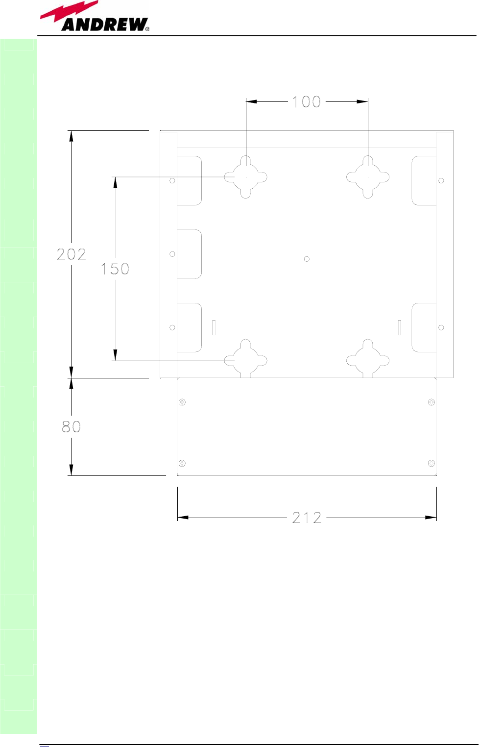
Fig. 3.15(b): External Power Supply layout with wall anchor quotes. It is highly recommended
to mount it on a vertical surface in vertical position with the socket downwards.
40 User Manual
TFAx
CaseA
Fig. 3.15(c): TKA layout with wall anchor quotes

41
MN024-08
Quick troubleshooting procedure
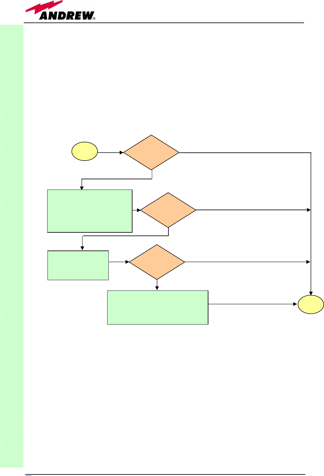
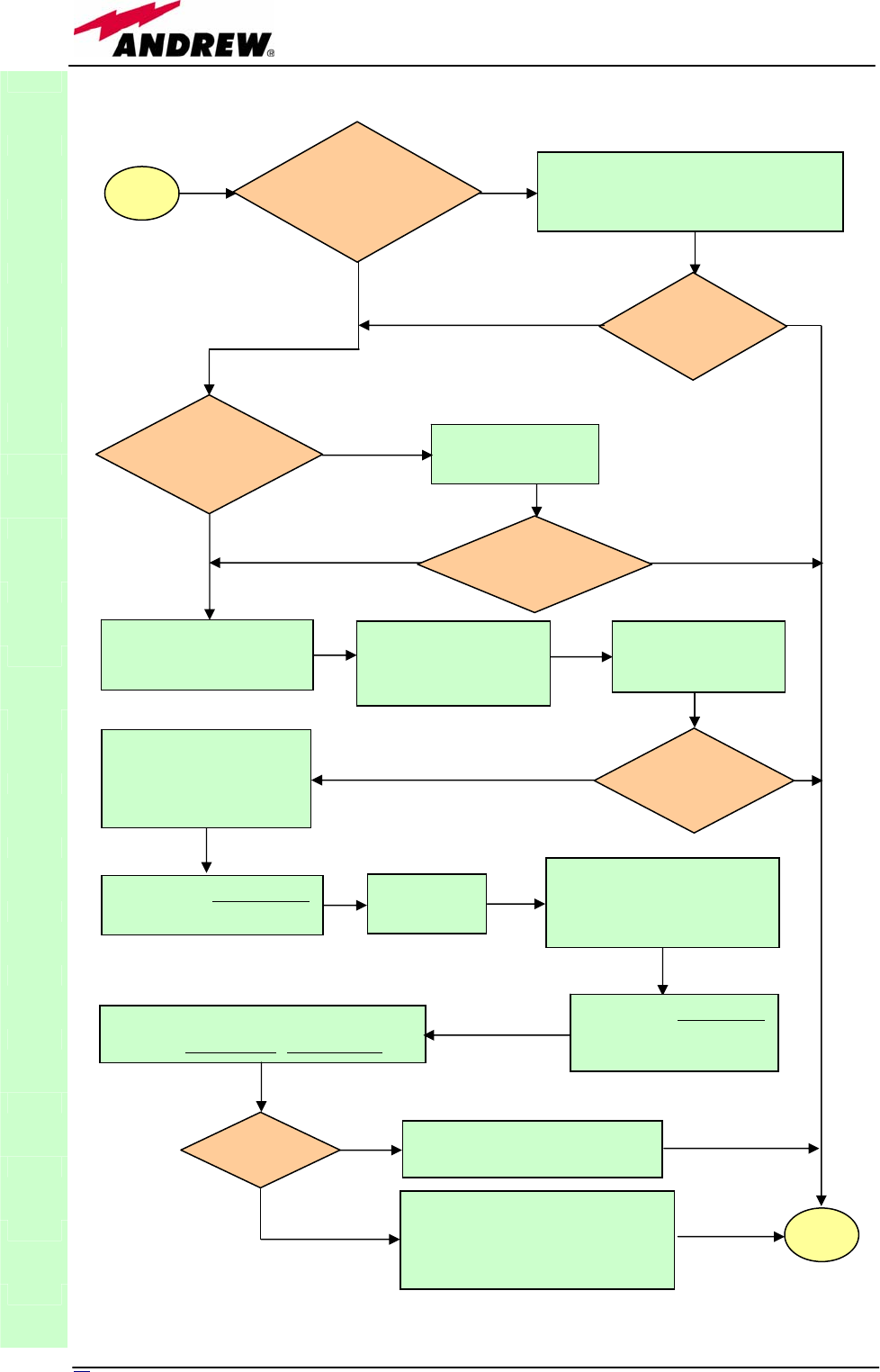
(The following procedure is summarized by the flow-chart in fig. 3.16a)
In case the red LED is ON, please follow these steps:
1. First of all, refer to dry-contact troubleshooting in order to understand
whether the alarm can depend on any external equipment failure or not.
2. In case dry-contact troubleshooting has not revealed any failure, clean the
optical adapters
3. If the problem still persists, refer to the fibre optic DL troubleshooting to
check if optical cables or optical connections have any problem on DL path.
4. If previous actions didn’t make the LED switch off replace the unit with a
new one or contact for assistance.
Dry contact troubleshooting
(The following procedure is summarized by the flow-chart in fig. 3.16b)
This procedure needs to be considered if at least one TFAx dry-contact is
connected to some external equipment. If not, return to main troubleshooting
procedure.
These steps aim to detect any failure inside the external equipment or inside
the dry-contact port. If dry-contacts don’t reveal equipment malfunction or a
port failure, return to the main troubleshooting procedure.
For any dry-contact connected to some external equipment, follow these
steps:
1. Disconnect it, and check the TFAx LED status after the disconnection.
2. If the red LED has switched off, external equipment connected to the dry
contact port should be faulty. Please test it.
3. If the TFAx red LED still remains on after the disconnection, measure
voltage between the terminals of the dry contact port.
a. If the terminals are electrically closed, the dry-contact port is faulty.
Contact the manufacturer for assistance.
b. If the terminals are open, this means neither the analysis of the
present dry contact nor the one of its external equipment has
revealed failures. Re-connect the present dry contact port to its
external equipment. In case the TFAx has another unchecked dry-
contact connected to some external equipment, apply the whole
procedure (i.e. the steps 1-3) to this new port
Fibre optic DL troubleshooting
(The following procedure is summarized by the flow-chart in fig. 3.16c)
1. Check if there is any point where fibre experiences a short radius of
curvature. In this case, rearrange the optical path in order to avoid sharp
bends (if necessary, replace the optical cable with a longer one). If TFLN
red LED switches off, troubleshooting has been successfully carried out.
Otherwise, follow next steps.
2. Check if SC-APC connectors are properly installed at both fibre ends. In
case they are not, fix better SC-SPC connectors to adapters. If TFLN red
LED switches off, troubleshooting has been successful. Otherwise, follow
next steps.
3. Disconnect the optical fibre and clean it better at both ends then clean
the SC-APC ports on both the TFLN and the remote unit. Re-connect the
fibre to relevant ports after cleaning. If it doesn’t made TFLN red LED
switch off, follow next steps.
TFAx
CaseA
42 User Manual
4. Disconnect the optical SC-APC connector from remote unit DL port, and
measure the output power POUT(DL) at the corresponding fibre end.
Then, go to the TFLN side, disconnect the optical SC-APC connector from
TFLN DL port and measure the input power PIN(DL) coming out of the
TFLN DL port. Calculate the DL fibre attenuation ADL as ADL [dB] =
PIN(DL) – POUT(DL)
a. If ADL > 4dB, then the fibre optic cable has some problems. Replace it
with a new one.
b. If ADL < 4dB troubleshooting procedure has not identified the problem.
Refer to supervision system or contact assistance.
TFAx
CaseA
Fig. 3.16( a): Flow-chart describing the quick troubleshooting procedure on Case A TFAx
star
t
Is the red LED
ON upon the
TFAx?
No
Yes
Yes
N
o
Verify if any external
equipment or any dry contact
port have some problems.
Refer to dry-contact
troubleshooting (fig. 3.16b)
Clean the SC-APC
optical adapters and
connectors
N
o
Yes
end
Is red LED upon
TFAx still ON?
Is red LED upon
TFAx still ON?
Optical cable or optical connections
are supposed to have problems on
DL path. Refer to fibre optic DL
troubleshooting (fig. 3.16c)
43
MN024-08
TFAx
CaseA
Fig. 3.16(b): Flow-chart describing the external alarm troubleshooting on Case A TFAx.
start
Is any dry contact
connected to some
external equipment?
No
Yes
Disconnect the
dry contact port
Is red LED
upon TFAx
still ON?
No
External equipment
connected to this dry
contact port should be
faulty. Test it.
Yes
Measure voltage between
the terminals of this dry
contact port
Is this dry contact
electrically closed?
The dry contact port
is faulty. Contact
the manufacturer
for assistance.
Yes
Analysis about this dry
contact and its external
equipment has not revealed
any failures.
Connect the dry contact to its
external equipment again.
Is the other dry
contact connected
to external
equipment?
No
Yes
No
end
44 User Manual
TFAx
CaseA
Fig. 3.16 (c): Flow-chart describing the fibre optic DL troubleshooting
start
Is there any
point where the
fibre experiences
a small radius of
curvature?
Rearrange the optical path to avoid
sharp bends. If necessary replace the
optical cable with a longer one.
Is red LED
upon remote
unit still ON?
Are SC-APC
connectors properly
installed at both fibre
ends?
Fix better SC-APC
connectors
Yes
N
o
N
o
Y
es
No
Y
es
N
o
Y
es
Disconnect the optical
SC-APC connector from
remote unit DL port
Clean optical SC-APC
ports on both TFL
N
and remote uni
t
.
Disconnect fibre optic
and clean it at both ends.
Reconnect the fibre
to relevant ports
Measure the output power
at corresponding fibre end.
Measure the input power
coming out of the TFLN
DL port.
Disconnect optical SC-APC
connector from TFLN DL
port.
Calculate DL fibre attenuation
ADL[dB]=input power - output power
Is ADL > 4dB? Fibre optic cable has some
problems. Replace it.
Troubleshooting procedure has
not identified the problem. Refer
to supervision system or contact
assistance
end
No
Y
es
No
Y
es
Is red LED
upon remote
unit still ON?
Is red LED
upon remote
unit still ON?
Go to TFLN
side.
45
MN024-08
3.3. Case B remote unit
Dimensions and Weight:
Dimensions: 38 x 240 x 240 mm
(1.5 x 9.4 x 9.4 inches)
Weight : please refer to the Bulletin
PA-100595EN or to the remote unit dedicated bulletin in order to
know the updated data about
the weight of your case L remote unit
TFAx
CaseB
Module name:
Remote Unit
TFAx
Case B
Power
Supply
connector
DL optical
port
(SC-APC)
External
alarm
connectors
Warm side
RF
antenna
port (N-f)
Green LED = power on
Red LED = major alarm
RF auxiliary
channel output
(
SMA-f
)
UL optical
port
(SC-APC)
RF
antenna
port (N-f)
RF auxiliary
channel input
(
SMA-f
)
RF ports:
• 2 RF antenna ports, transmitting/receiving signals to/from
distributed antennas. RF antenna ports are duplexed N-female
connectors. These RF ports can be connected to the antennas
either directly (ie. through RF jumper cables) or through
splitters, thus allowing more antennas to be fed. Unused RF
ports have to be terminated with a 50 Ω load.
• 1 RF auxiliary input and 1 auxiliary output (designed to
receive and transmit additional signals). Auxiliary input and
output ports are SMA-female connectors.
Optical ports: • 1 optical output port, transmitting UL signals to TFLN
master optical TRX
• 1 optical input port, receiving DL signals from TFLN
master optical TRX
Fig. 3.17: 3D-drawing of
a Case B remote unit
46 User Manual
Visual alarms:
Two control LEDs are provided on the TFAx front side (fig.3.18). The green
LED describes the power supply status, while the red LED describes the major
Remote Unit failures (please refer to the table 3.4).
Dry contact alarms:
TFAx is provided with two dry contacts inputs, which can
be connected (through .062” MOLEX plugs) to any external
device. In such a way, the alarm information about this
external device can be signalled through the red LED of
TFAx LED panel and displayed into the supervision system.
Power supply
The Case B remote unit is provided with an external power supply TPSN (fig.
3.20 a,b), available either for universal mains (90 to 264) or for negative
supply. (-72 to -36 Vdc). Each TPSN external power supply provides the
remote units with a +5Vdc power, by means of a 3-pole connector (fig.
3.20c).
Warnings (to be read before remote units are
installed)
Dealing with optical output ports
The TFAx remote unit contains semiconductor lasers. Invisible laser beams
may be emitted from the optical output ports. Do not look towards the optical
ports while equipment is switched on.
TFAx
CaseB
Led colour Meaning
Red Low optical power at DL input
and/or RF amplifier failure
Green Power supply OK
Fig. 3.18 : LED panel on
the Case-B warm side
Table 3.4: summary of TFAx LEDs meaning
dr
y
contacts
Fig. 3.19 : Dry-contacts
on Case B back side
4
7
MN024-08
Choosing a proper installation site for the remote units
• TFAx remote units have to be installed as close as possible to the radiating
antennas, in order to minimize coaxial cable length, thus reducing downlink
power loss and uplink noise figure.
• When positioning the TFAx remote unit, pay attention that the placing of
related antennas should be decided in order to minimize the Minimum
Coupling Loss (MLC), so as to avoid blocking.
• The TFAx remote unit is intended to be fixed on walls, false ceilings or
other flat vertical surfaces (TKA installation kits are available, in order to
provide a protective cover for TFAx remote unit, while making the TFAx
installation easier and faster).
Handling optical connections
• When inserting an optical connector, take care to handle it so smoothly
that the optical fibre is not damaged. Optical fibres are to be single-mode
(SM) 9.5/125µm.
• Typically, Britecell Plus equipment is provided with SC-APC optical
connectors (other connectors may be provided on request). Inserting any
other connectors will result in severe damages.
• Do not force or stretch the fibre pigtail with radius of curvature less than
5cm. See rightward figure for optimal fibre cabling.
• Remove the adapter caps only just before making connections. Do not
leave any SC-APC adapter open, as they attract dirt. Unused optical
connectors must always be covered with their caps.
• Do not touch the connector tip. Clean it with a proper tissue before
inserting each connector into the sleeve. In case connector tips need to be
cleaned, use pure ethyl alcohol.
TFAx
CaseB
Fig. 3.20: TPSN external adapters for 220
Vac (a) and -48 Vdc (b) Case B remote
units. Power supply connector on the rear
side of Case-B remote unit (c).
Ground
Positive +5 Vdc
(a)
(c)
(b)

48 User Manual
TFAx Case B installation
CaseB remote unit can be fixed on walls, false ceilings or other flat vertical
surfaces, either directly or through a TKA04 installation kit (optional).
Installing a Case B remote unit WITHOUT the TKA kit
The TFAx kit includes:
Please consider carefully these guidelines in order to choose a proper
positioning of the remote unit and of its power supply:
o Each piece of equipment should not be affected by the heating of any other
piece. The remote unit and its external power supply should be mounted so
as to avoid reciprocal heating. Side-by-side configuration is suggested (fig.
3.22 a,b)
o Remote units are provided with cooling fins which allow to optimize heat
dissipation. In order to let them work, the environment where the TFAx is
mounted should allow the necessary air changeover
o It is strongly recommended not to mount the external power supply on a
horizontal surface, because this position does not allow heat dissipation.
External power supplies must be mounted on vertical surfaces.
o In order to assure a proper heat dissipation, the external power supplies
must be mounted in vertical position with the power socket downwards
(see fig. 13.22a,b).
Once you have chosen the position of the remote unit, please follow these
instructions:
1. In order to install the M4 screw anchors (not included) which shall hold up
the TFAx remote unit, drill into the wall according to the case B layout
shown in fig. 3.24a.
2. Fix the TFAx to the wall by firmly screwing the anchors.
3. In order to install the M4 screw anchors (not included) which shall hold up
the power supply external adapter, drill into the wall according to the
power supply layout shown in fig.3.24b
4. Fix the external power supply adapter to the wall by firmly screwing the
anchors.
5. Take the splice – tray (not included). Fix the splice holder inside the splice
tray. (see fig. 3.21a,b)
TFAx
CaseB
a. a remote unit TFAx
b. a 50 Ω load
c. a TPSN external power supply adapter (86 to 264
Vac or -72 to -36 Vdc, according to the chosen
model)
d. a VDE connector or a -48 Vdc plug (according to
the chosen model)
49
MN024-08
6. Splice the optical fibres and close the splice tray. While handling the fibers,
take care of the fiber bending.
7. Fix the splice tray beside the remote unit
8. Connect the external adapter to the TFAx remote unit through the proper
cable.
9. If the remote unit is -48 Vdc powered, use the -48 Vdc plug (included) in
order to connect the external adapter to the -48 Vdc supply (fig. 3.22b).
If the remote unit is 90/264 Vac-powered, fix the 90/264 Vac plug
(included) on to a power cord (not included), and use this cable in order to
connect the external adapter to the mains (fig. 3.22a).
10. Connect the antenna RF cables to the RF antenna ports. Connect the UL
and DL optical connectors.
11. Once the installation is finished, please follow the section “TFAx Case B
Start-up” in order to carry out a proper system start up.
TFAx
CaseB
(a)
(b)
Fig. 3.21. (a) Splice tray. (b) Inside of the splice tray,
with the splice holder properly positioned.
Fig. 3.22. Example of proper mounting configuration, which assures heat dissipation. Note that
the remote unit and its power supply adapter are mounted side-by-side, and the power supply
adapter has the socket downwards. The pictures refer to a 90/264 Vac – powered TFAx Case B
(a) and to a -36/-72 Vdc –powered TFAx Case B (b).
(a) (b)
Universal mains
(90 to 264 Vac) Neg. supply
(-72 to -36 Vdc )
50 User Manual
Installation of the Case B remote unit WITH the TKA04 installation kit
The TFAx Case B kit includes:
The TKA04 kit includes:
Please consider carefully these guidelines in order to choose a proper
positioning of the remote unit and of its power supply:
o Each piece of equipment should not be affected by the heating of any other
piece. The remote unit and its external power supply should be mounted so
as to avoid reciprocal heating. Side-by-side configuration is suggested (fig.
3.24 a,b)
o It is strongly recommended not to mount the external power supply on a
horizontal surface, because this position does not allow heat dissipation.
External power supplies must be mounted on vertical surfaces.
o In order to assure a proper heat dissipation, the external power supplies
must be mounted in vertical position with the power socket downwards
(see fig. 3.24a,b).
Once you have chosen the position of the remote unit mounting case, please
follow these instructions:
1. Unscrew the 4 screws which lock the lower cover of the TKA04 wall bearing
(see fig. 3.26a)
2. In order to install the M4 screw anchors (included) which shall hold up the
TKA04 wall bearing, drill into the wall according to the TKA layout shown in
fig. 3.25c.
TFAx
CaseB
Fig. 3.23: The TKA installation kit
2. a remote unit TFAx
3. a 50 Ω load
4. a TPSN external power supply adapter (86
to 264 Vac or -72 to -36 Vdc, according to
the chosen model)
5. a VDE connector or a -48 Vdc plug
(
accordin
g
to the chosen model
)
A. 4 screw anchors (fixing the wall bearing to the
wall)
B. 5 screw anchors (fixing the TFAx Case B to the
wall bearing)
C. a wall mounting box (wall bearing + cover)
D. a splice holder
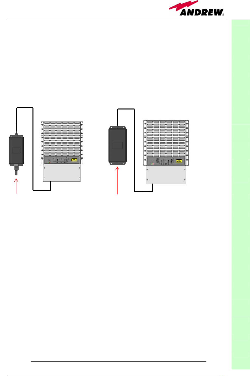
51
MN024-08
3. Fix the TKA04 wall bearing by firmly screwing the anchors.
4. In order to install the M4 screw anchors (not included) which shall hold up
the power supply external adapter, drill into the wall according to the power
supply layout shown in fig.3.25b.
5. Fix the external power supply adapter to the wall by firmly screwing the
anchors.
6. Carefully open the splice tray by using a screwdriver as in fig. 3.26b. Fix the
splice holder inside the splice tray (fig. 3.26c). Splice the optical fibres and
close the splice tray. While handling the fibers, take care of the fiber
bending. Close the splice tray.
Fig. 3.24. Example of proper mounting configuration, which assures proper heat dissipation. Note
that the remote unit and its power supply adapter are mounted side-by-side, and the power supply
adapter has the socket downwards. The pictures refer to a 220 Vac – powered TFAx Case B (a)
and to a -48 Vdc –powered TFAx Case B (b).
7. Fix the remote unit to the wall-bearing by using the included screws (fig.
3.26d).
8. If the remote unit is -48 Vdc powered, use the -48 Vdc plug (included) in
order to connect the external adapter to the -48 Vdc mains (fig. 3.24b).
If the remote unit is 90/264 Vac-powered, fix the 90/264 Vac plug
(included) on to a power cord (not included), and use this cable in order to
connect the external adapter to the mains (fig. 3.24a).
9. Connect the antenna RF cables to the RF antenna ports. Connect the UL
and DL optical connectors (fig. 3.26e). If the power cable has properly
been connected to the main, both the green and the red LEDs should turn
on. The green LED will remain on to indicate that the unit is powered on,
while the red LED will turn off as soon as the local unit will be switched on
(for further details about the start up of the system, please refer to the
section “TFAx Case B Start-up”)
10. Fix the lower cover by fastening the 4 screws (fig. 3.26f)
TFAx
CaseB
(a) (b)
Universal mains
(90 to 264 Vac) Neg. supply
(-72 to -36 Vdc

52 User Manual
TFAx Case B start-up
Before the TFAx remote unit is switched on, make sure that:
• the modules hosted in the master unit have been connected each other
with RF jumpers, according to the system design
• every TFLN master optical TRX has been connected to its remote units
• each remote unit has been connected to its coverage antennas
For a correct system start-up, all the remote units have to be
switched on before the master unit.
Once the TFAx has been switched on, its behaviour can be summarized as per
the following steps:
1. When the remote unit is turned on, both the LEDs upon the warm side turn
on for a couple of seconds
2. After that, the unit green LED remains on (thus indicating proper power
supply), while the red LED switches off as soon as the master unit is turned
on (meaning that DL optical power is OK and no alarms are present).
3. Once the master unit has been switched on, the status of both LEDs have
to be the one reported in table 3.4. In case the red LED remains on, please
refer to the troubleshooting section.
4. After being switched on the remote unit starts working correctly. Anyway,
in order to be recognized by the supervision management system, it is
necessary for the corresponding TFLN master optical TRX to carry out the
discovery phase (please refer to Supervision System Manual for more
details). During this phase which can last at max. 4min, depending on the
system complexity, the TFLN LED ┌┘ blinks. Do not connect/disconnect
any cable or any piece of equipment during the discovery phase!
This may result in failing the identification of the remote unit.
Note: in case discovery doesn’t start automatically, check through the LMT or
the remote supervision whether it has been disabled (refer to LMT or remote
supervision system manuals for further information).
TFAx Case B troubleshooting
Faults can be revealed by LEDs on the TFAx front panel as well as by LMT or
supervision system (running on the remote supervision unit)
Both LMT and supervision system provide full information about the device
causing the alarm. As a consequence, troubleshooting procedure can be very
immediate when failure detection is directly carried out through LMT or
supervision system.
Britecell Plus modules are designed in order to exchange information, so that
each remote unit can receive failure notifications from its external equipment
through dry-contact connections. Moreover, the TFAx constantly monitors the
optical signal received from its TFLN unit to control optical losses.
TFAx
CaseB
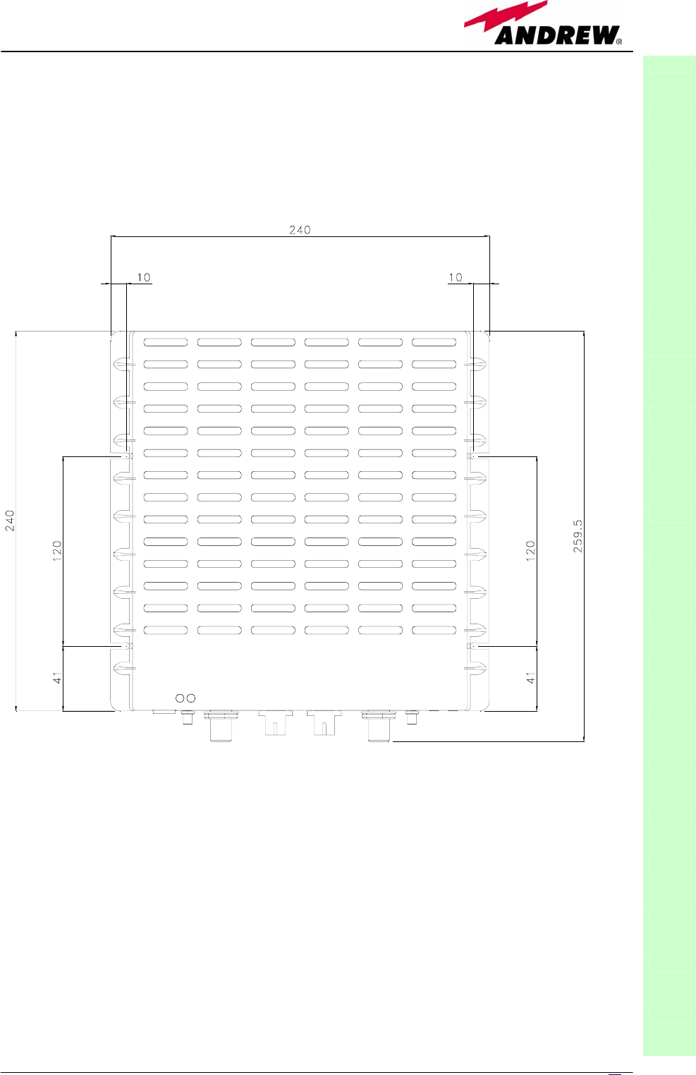
53
MN024-08
TFAx
CaseB
Fig. 3.25 (a): CASE B layout with wall anchor quotes
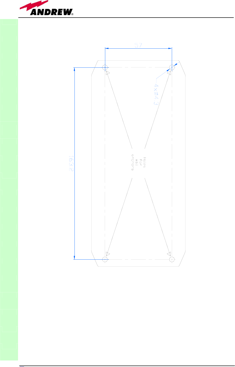
54 User Manual
TFAx
CaseB
Fig. 3.25 (b): External Power Supply layout with wall anchor quotes. It is highly recommended
to mount it on a vertical surface in vertical position with the socket downwards.
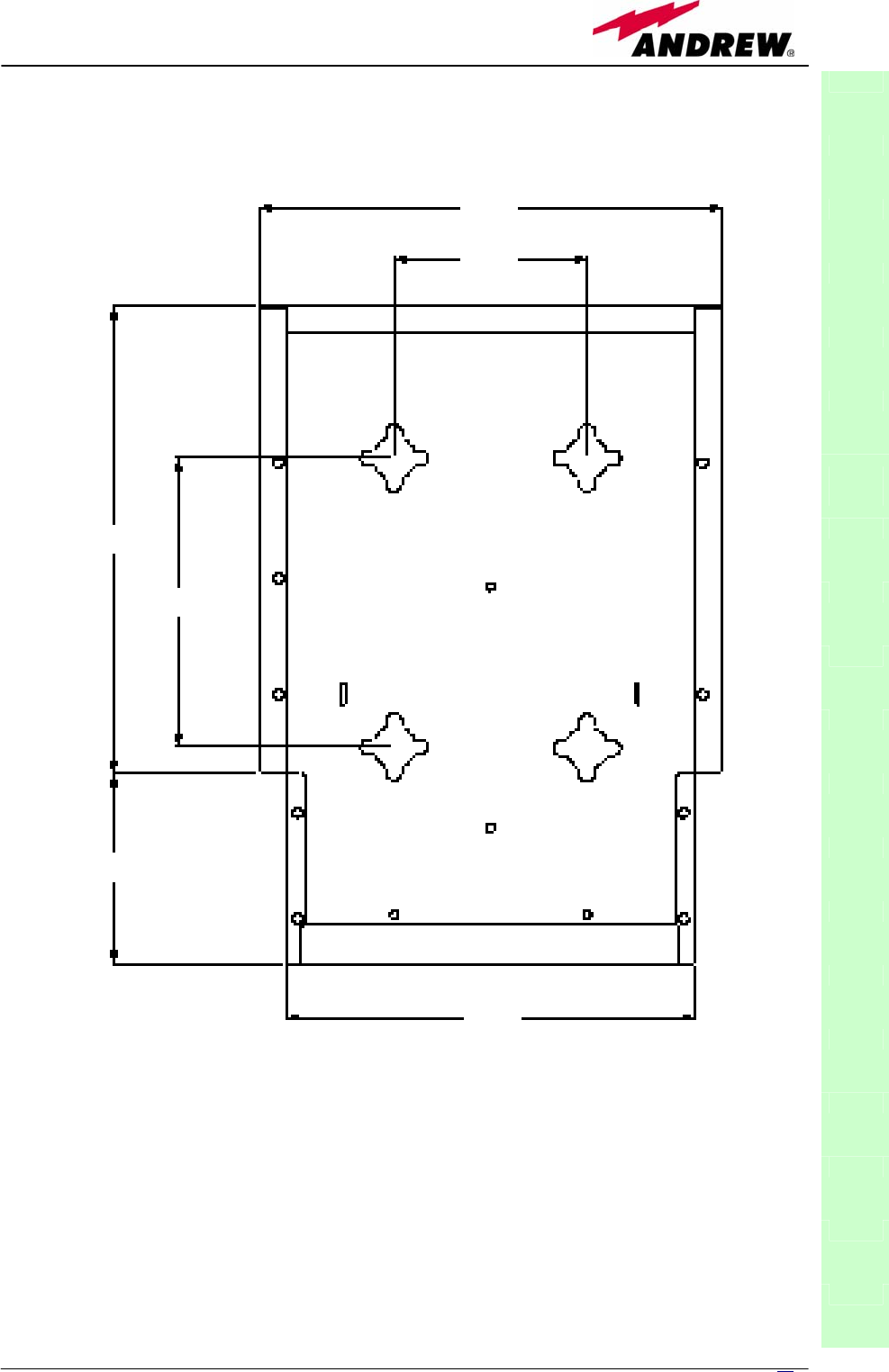
55
MN024-08
TFAx
CaseB
Fig. 3.25 (c): TKA layout with wall anchor quotes
240
100
242
150
98
2
12
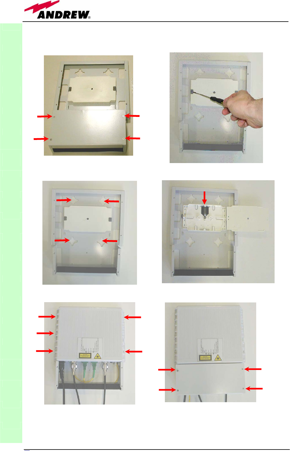
56 User Manual
TFAx
CaseB
(a)
(c) (d)
(e) (f)
Fig. 3.26: Mounting the TFAx with a TKA installation kit. Please note that these
p
itctures refers to the mounting of a Case A TFAx with a TKa01 kit. However, the
installation procedure is identical for mounting a TFAx case B with a TKA04 kit.
(b)

5
7
MN024-08
Tables 3.5 and 3.6 show a brief description of the alarms related to a Case B
remote unit, with a reference to the corresponding alerted LEDs and to the
actions to be carried out in the case of a fault.
TFAN (tri band)
ALARM
CODE
(TSUN
description)
ALARM
DESCRIPTION ACTIVE LED
SUPERVISION
PRIORITY
LEVEL
ACTION
RECOMMENDED
RELÉ
PRIORITY
LEVEL
(subrack)
Antenna DC
loop alarm ALWAYS OK
DL optical power
fail1
The optical power
received on the DL is
too low and can’t no
more be
compensated
RED MAJOR
Check the DL fibre
and the TFLN laser
status MAJOR
AGC out of
range1
The optical power
received is under the
allowed 3dB optical
loss but it can be
compensated
NONE WARNING
Clean optical
connectors MINOR
DL RF low band
alarm HW failure on the DL
low band RF section RED CRITICAL Return the unit MAJOR
DL RF high
band alarm HW failure on the DL
high band RF section RED CRITICAL Return the unit MAJOR
External 1 alarm Alarm on the device
connected on dry-
contact 1 RED MAJOR
Check the external
device or alarm
connection MAJOR
External 2 alarm Alarm on the device
connected on dry-
contact 2 RED MAJOR
Check the external
device or alarm
connection MAJOR
Power supply
alarm
UPS HW failure or
malfunction.
RF is turned OFF RED MAJOR
Check the external
PSU. If it works
properly, return the
unit
MAJOR
Internal BUS
alarm
A malfunctioning on
the digital part
involves a fault in
monitoring
functionalities
RED CRITICAL Return the unit MAJOR
Temperature
alarm Over-temperature
alarm NONE MINOR
Check ventilation
and environment MINOR
DL UMTS band
alarm
HW failure on the DL
UMTS band RF
section RED CRITICAL Return the unit MAJOR
TFAx
CaseB
Table 3.5. Description of the alarms of the TFAN Case-B Remote Unit,
as they are presented on LMT or Supervision Interface

58 User Manual
TFAM
ALARM
CODE
(TSUN
description)
ALARM
DESCRIPTION
ACTIVE
LED
SUPERVISION
PRIORITY
LEVEL
ACTION
RECOMMENDED
RELÉ
PRIORITY
LEVEL
(subrack)
Antenna DC
loop alarm ALWAYS OK
DL optical
power fail1
The optical power
received on the DL is
too low and can’t no
more be
compensated
RED MAJOR
Check the DL fibre
and the TFLN laser
status MAJOR
AGC out of
range1
The optical power
received is under the
allowed 3dB optical
loss but it can be
compensated
NONE WARNING
Clean optical
connectors MINOR
DL UMTS
band alarm HW failure on the DL
UMTS section RED CRITICAL Return the unit MAJOR
External
1alarm
Alarm on the device
connected on dry-
contact 1 RED MAJOR
Check the external
device or alarm
connection MAJOR
External 2
alarm
Alarm on the device
connected on dry-
contact 2 RED MAJOR
Check the external
device or alarm
connection MAJOR
Power Supply
alarm
UPS HW failure or
malfunction.
RF is turned OFF RED MAJOR
Check the external
PSU. If it works
properly, return the
unit
MAJOR
Internal Bus
alarm ALWAYS OK
As the tables show minor alarms (low priority alarms) are revealed only by
LMT or supervision system, but not by LEDs. Minor alarms detect critical
situations which should be checked and tested in order to avoid future
possible system faults.
Each remote unit is provided with an AGC system which comes in after the
optical-to-RF conversion. This AGC can correctly compensate optical losses
when these are estimated to be <3 dB. In case optical losses are in the 3dB-
4dB range, the whole system still works, but AGC is near to its borderline
levels. The red LED switches on when the estimated optical losses are >4dB,
the AGC not being able to compensate these losses any more.
As shown in the previous table, the same red LED switches on to reveal any
major failure. Following the troubleshooting procedure reported hereinafter it
is possible to better understand what problem occurred.
1Note:
Each remote unit is provided with an AGC system which comes in after the optical-to-RF
conversion. This AGC can correctly compensate optical losses when these are estimated to be
<3 dB. In case optical losses are in the 3dB- 4dB range, the AGC is said to be “out of range”:
the whole system still work, but AGC is near to its borderline levels. The DL power LED
switches on when the estimated optical losses are >4dB, the AGC not being able to
compensate these losses any more.
TFAx
CaseB
Table 3.6. Description of the alarms of the TFAM Case-B Remote Unit,
as they are presented on LMT or Supervision Interface

59
MN024-08
As shown in the previous table, the same red LED switches on to reveal any major failure.
Following the troubleshooting procedure reported hereinafter it is possible to better understand
what problem occurred.
Quick troubleshooting procedure
(The following procedure is summarized by the flow-chart in fig. 3.27a)
In case the red LED is ON, please follow these steps:
1. First of all, refer to dry-contact troubleshooting in order to understand
whether the alarm can depend on any external equipment failure or not.
2. In case dry-contact troubleshooting has not revealed any failure, clean the
optical adapters
3. If the problem still persists, refer to the fibre optic DL troubleshooting to
check if optical cables or optical connections have any problem on DL path.
4. If previous actions didn’t make the LED switch off replace the unit with a
new one or contact for assistance.
Dry-contact troubleshooting
(The following procedure is summarized by the flow-chart in fig. 3.27b)
This procedure needs to be considered if at least one TFAx dry-contact is
connected to some external equipment. If not, return to main troubleshooting
procedure.
These steps aim to detect any failure inside the external equipment or inside
the dry-contact port. If dry-contacts don’t reveal equipment malfunction or a
port failure, return to the main troubleshooting procedure.
For any dry-contact connected to some external equipment, follow these
steps:
1. Disconnect it, and check the TFAx LED status after the disconnection.
2. If the red LED has switched off, external equipment connected to the dry
contact port should be faulty. Please test it.
3. If the TFAx red LED still remains on after the disconnection, measure
voltage between the terminals of the dry contact port.
a. If the terminals are electrically closed, the dry-contact port is
faulty. Contact the manufacturer for assistance.
b. If the terminals are open, this means neither the analysis of the
present dry contact nor the one of its external equipment has
revealed failures. Re-connect the present dry contact port to its
external equipment. In case the TFAx has another unchecked dry-
contact connected to some external equipment, apply the whole
procedure (ie steps 1-3) to this new port
Fibre optic DL troubleshooting
(The following procedure is summarized by the flow-chart in fig. 3.27c)
1. Check if there is any point where fibre experiences a short radius of
curvature. In this case, rearrange the optical path in order to avoid sharp
bends (if necessary, replace the optical cable with a longer one). If TFLN red
LED switches off, troubleshooting has been successfully carried out.
Otherwise, follow next steps.
2. Check if SC-APC connectors are properly installed at both fibre ends. In
case they are not, fix better SC-SPC connectors to adapters. If TFLN red
LED switches off, troubleshooting has been successful. Otherwise, follow
next steps.
TFAx
CaseB
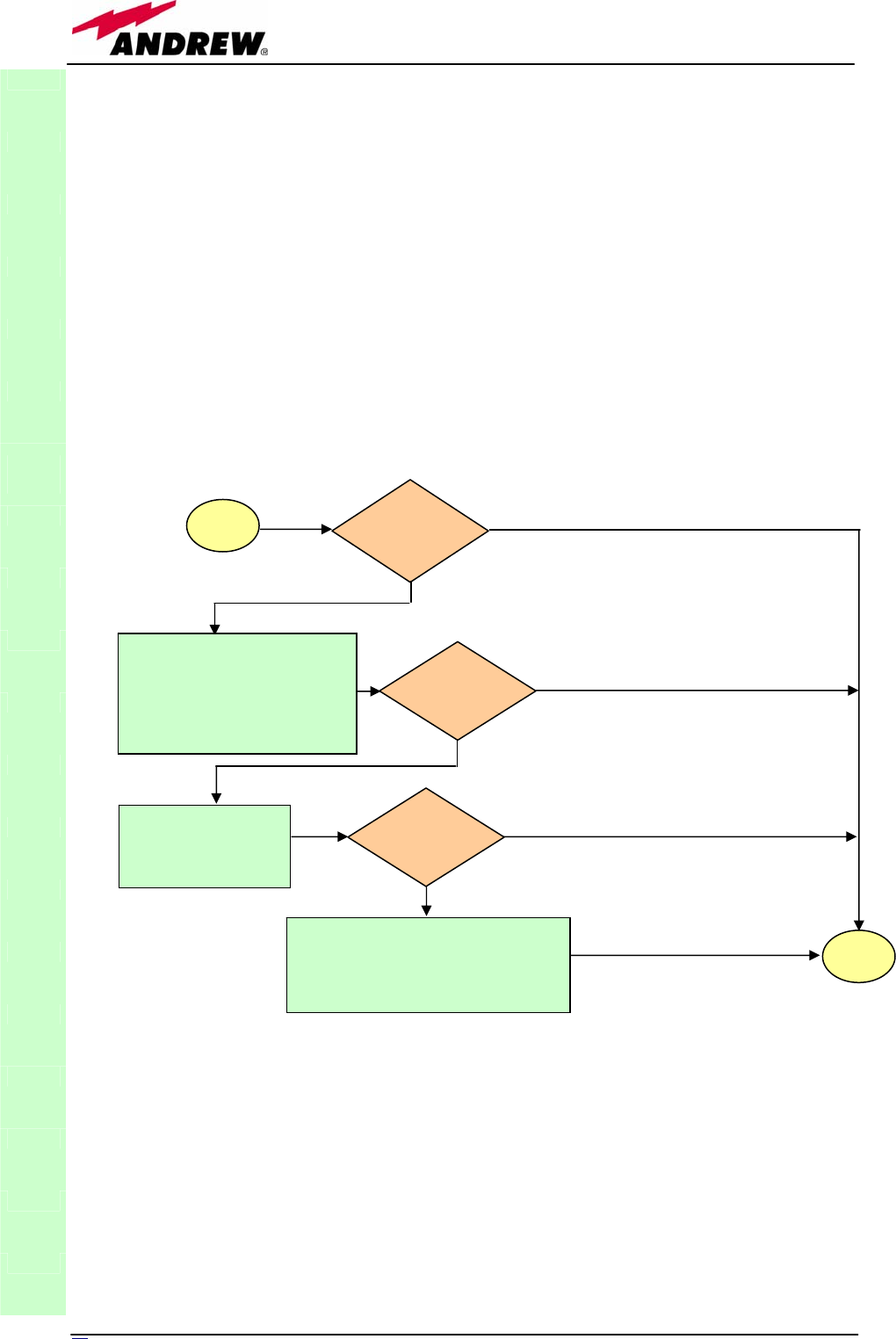
60 User Manual
3. Disconnect the optical fibre and clean it better at both ends then clean the
SC-APC ports on both the TFLN and the remote unit. Re-connect the fibre
to relevant ports after cleaning. If it doesn’t made TFLN red LED switch off,
follow next steps.
4. Disconnect the optical SC-APC connector from remote unit DL port, and
measure the output power POUT(DL) at the corresponding fibre end. Then,
go to the TFLN side, disconnect the optical SC-APC connector from TFLN DL
port and measure the input power PIN(DL) coming out of the TFLN DL port.
Calculate the DL fibre attenuation ADL as ADL [dB] = PIN(DL) – POUT(DL)
a. If ADL > 4dB, then the fibre optic cable has some problems.
Replace it with a new one.
b. If ADL < 4dB troubleshooting procedure has not identified the
problem. Refer to supervision system or contact assistance.
TFAx
CaseB
Fig. 3.27 (a): Flow-chart describing the quick troubleshooting procedure on TFAx Case B
start Is the red LED
ON upon the
TFAx?
No
Yes
Yes
N
o
Verify if any external
equipment or any dry contact
port have some problems.
Refer to dry-contact
troubleshooting (fig. 3.27b)
Clean the SC-APC
optical adapters and
connectors
N
o
Yes
end
Is red LED
upon TFAx still
ON?
Is red LED
upon TFAx still
ON?
Optical cable or optical connections
are supposed to have problems on
DL path. Refer to fibre optic DL
troubleshooting (fig. 3.27c)
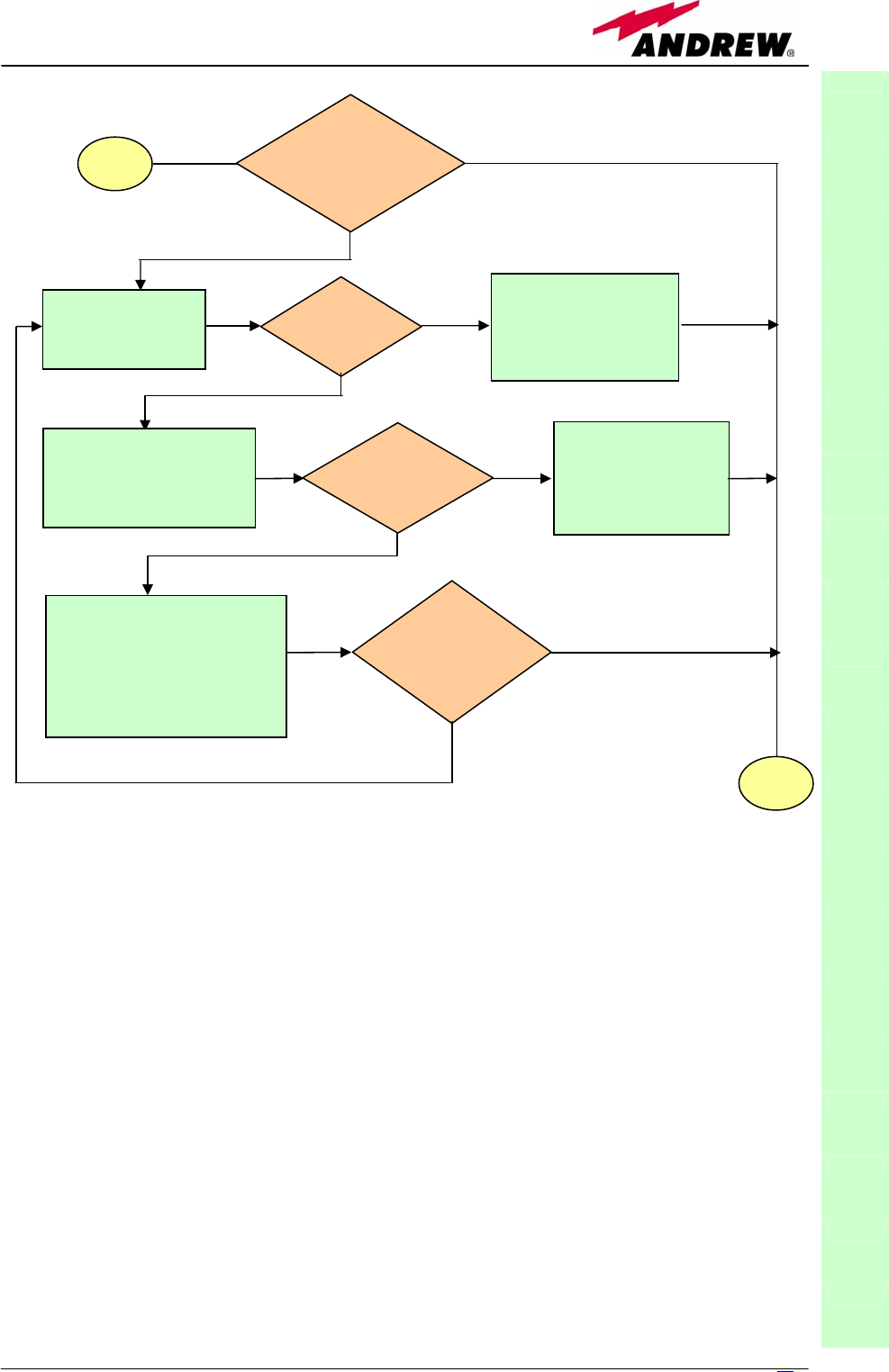
61
MN024-08
TFAx
CaseB
Fig. 3.27 (b): Flow-chart describing the external alarm troubleshooting on Case B TFAx.
start
Is any dry contact
connected to some
external equipment?
No
Yes
Disconnect the
dry contact port
Is red LED
upon TFAx
still ON?
No
External equipment
connected to this dry
contact port should be
faulty. Test it.
Yes
Measure voltage between
the terminals of this dry
contact port
Is this dry contact
electrically closed?
The dry contact port
is faulty. Contact
the manufacturer
for assistance.
Yes
Analysis a
b
out this dry
contact and its external
equipment has not revealed
any failures.
Connect the dry contact to its
external equipment again.
Is the other dry
contact connected
to external
equipment?
No
Yes
No
end
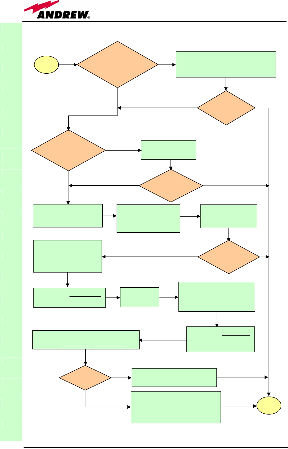
62 User Manual
TFAx
CaseB
Fig. 3.27 (c): Flow-chart describing the fibre optic DL troubleshooting
start
Is there any
point where the
fibre experiences
a small radius of
curvature?
Rearrange the optical path to avoid
sharp bends. If necessary replace the
optical cable with a longer one.
Is red LED
upon remote
unit still ON?
Are SC-APC
connectors properly
installed at both fibre
ends?
Fix better SC-APC
connectors
Yes
N
o
N
o
Y
es
No
Y
es
N
o
Y
es
Disconnect the optical
SC-APC connector from
remote unit DL port
Clean optical SC-APC
ports on both TFL
N
and remote uni
t
.
Disconnect fibre optic
and clean it at both ends.
Reconnect the fibre
to relevant ports
Measure the output power
at corresponding fibre end.
Measure the input power
coming out of the TFLN
DL port.
Disconnect optical SC-APC
connector from TFLN DL
port.
Calculate DL fibre attenuation
ADL[dB]=input power - output power
Is ADL > 4dB? Fibre optic cable has some
problems. Replace it.
Troubleshooting procedure has
not identified the problem. Refer
to supervision system or contact
assistance
end
No
Y
es
No
Y
es
Is red LED
upon remote
unit still ON?
Is red LED
upon remote
unit still ON?
Go to TFLN
side.
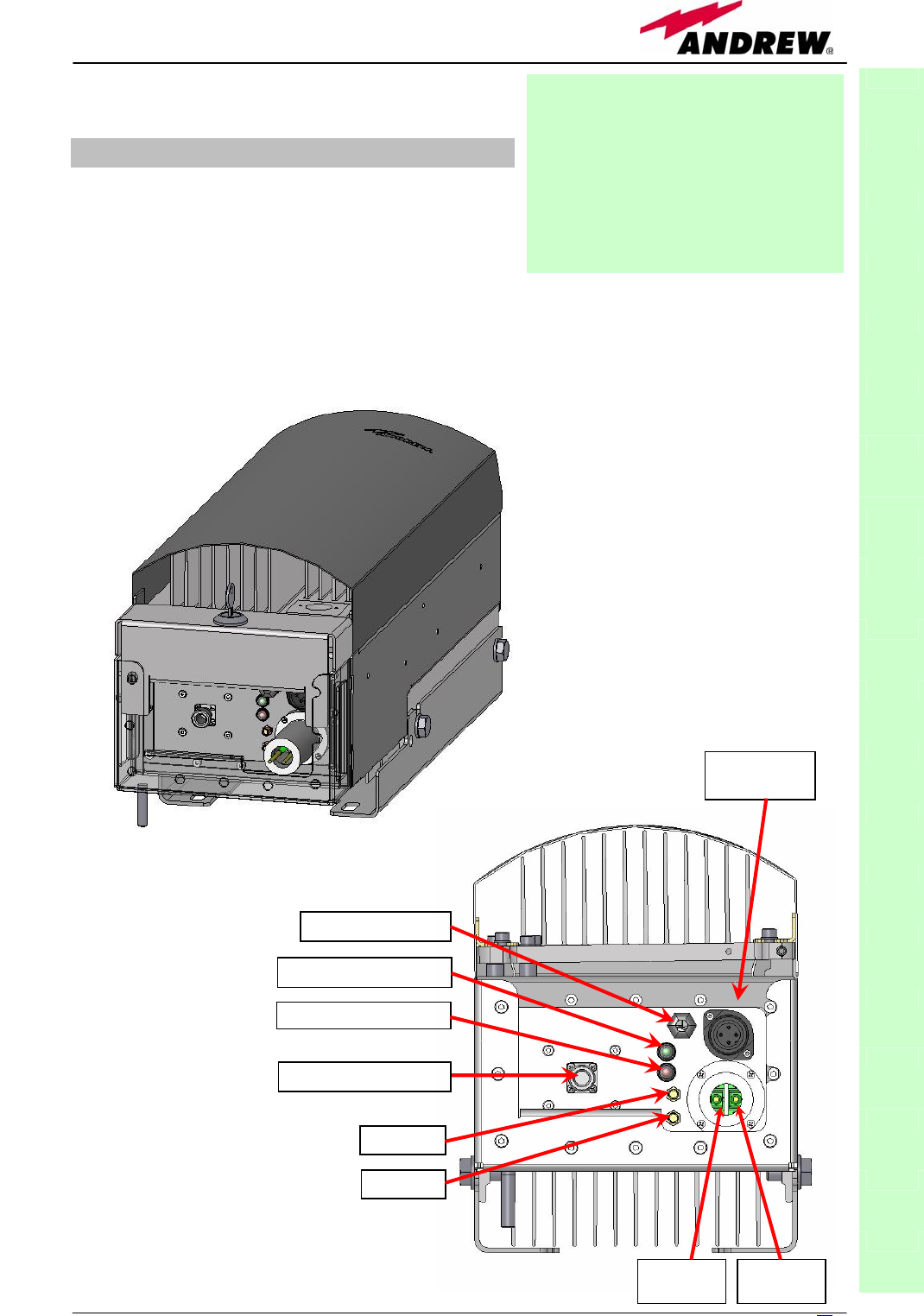
63
MN024-08
3.4. Case F remote unit
Dimensions and Weight
Dimensions: 546 x 253 x 207 mm
(inches 21.5 x 10 x 8.1)
Weight: please refer to the Britecell Plus bulletin PA-100595EN or to
the remote unit dedicated bulletin in order to know the
updated data about the weight of your case-L remote unit.
TFAx
CaseL
Figure 3.28 : (a) Case-L remote
unit; (b) connection panel of the
Case-L remote unit
Module name:
Remote Unit
TFAH
Case L
(a)
(b)
External alarms port
Green LED = power ON
UL AUX
DL AUX
Red LED = ma
j
or alarm
Power supply
connector
RF ANTENNA PORT
DL optical
cable UL optical
cable
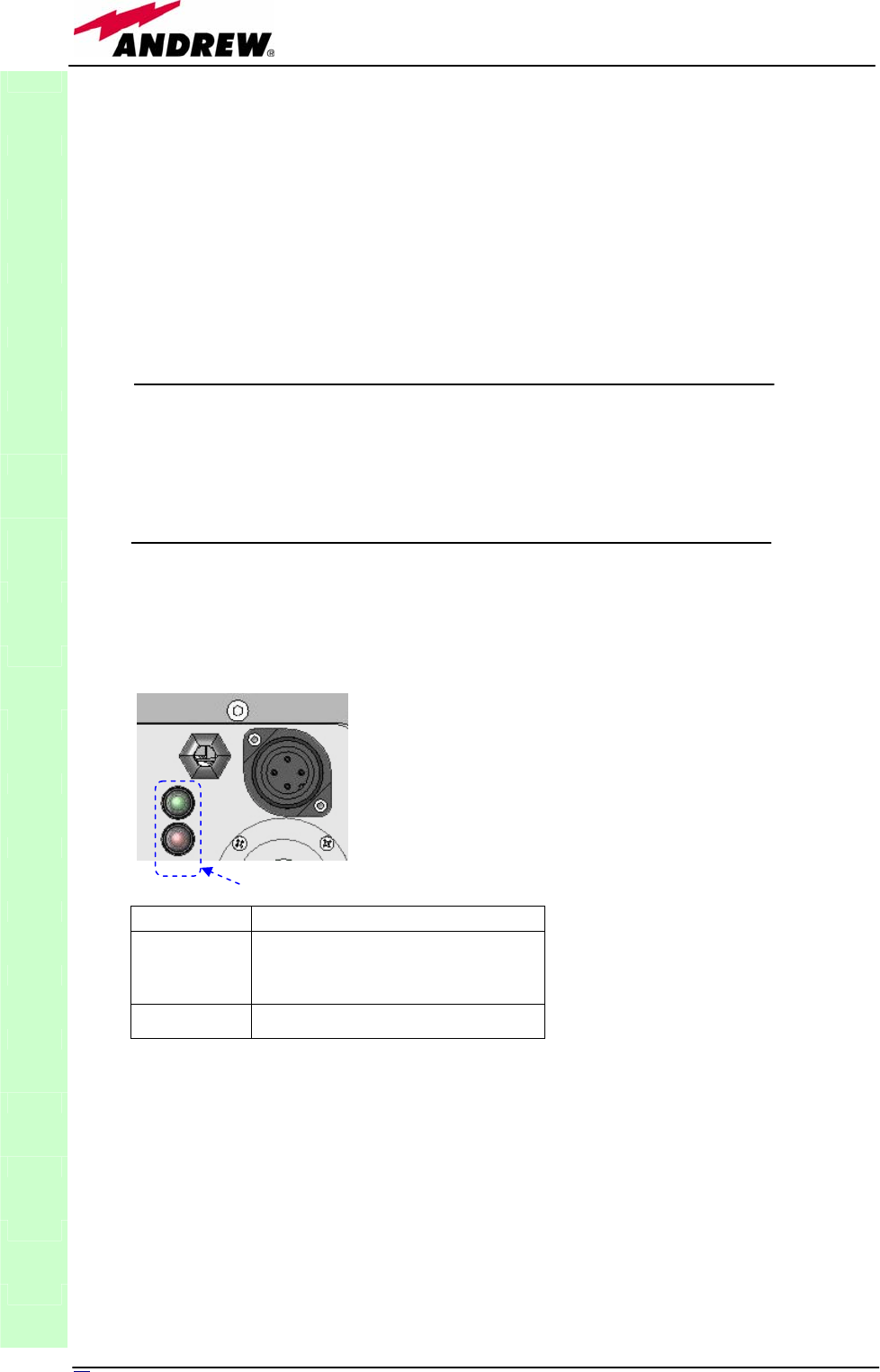
64 User Manual
RF ports:
• 1 RF antenna port, transmitting/receiving signals to/from distributed
antennas. This RF antenna port is a duplexed N-female connectors. The
port can be connected to the antenna either directly (ie. through RF jumper
cables) or through splitters, thus allowing more antennas to be fed.
• 1 RF auxiliary input and 1 RF auxiliary output (designed to receive and
transmit additional signals). Auxiliary input and output ports are SMA-
female connectors.
Optical ports:
• 1 optical output port, transmitting UL signals to TFLN master optical TRX;
• 1 optical input port, receiving DL signals from TFLN master optical TRX.
Visual alarms:
Two control LEDs are provided on the Case-L upper side (see fig. 3.29).
The green LED describes the power supply status, while the red LED describes
the major Remote Unit failures (please rfer to the table 3.7).
External alarms
The Case-L remote unit can collect the alarm information of any external
device, so that the two LEDs of the visual panel will take account both of the
alarms of the remote unit itself and of the external devices which have been
properly connected. The alarms signals coming from external devices can be
carried through proper cables (provided with 0.62” molex plugs), which have
to pass through the external alarms port (see picture 3.28) and have to be
connected to the proper pins on the motherboard.
Please refer to fig. 3.30 in order to connect the external alarms cables to the
proper pins.
TFAx
CaseL
Led colour Meaning
Red
Low optical power at DL
input and/or RF amplifier
failure
Green Power supply OK
Table 3.7: summary of
Case-L LEDs meaning
Fig. 3.29 : LED panel on the Case-B warm side
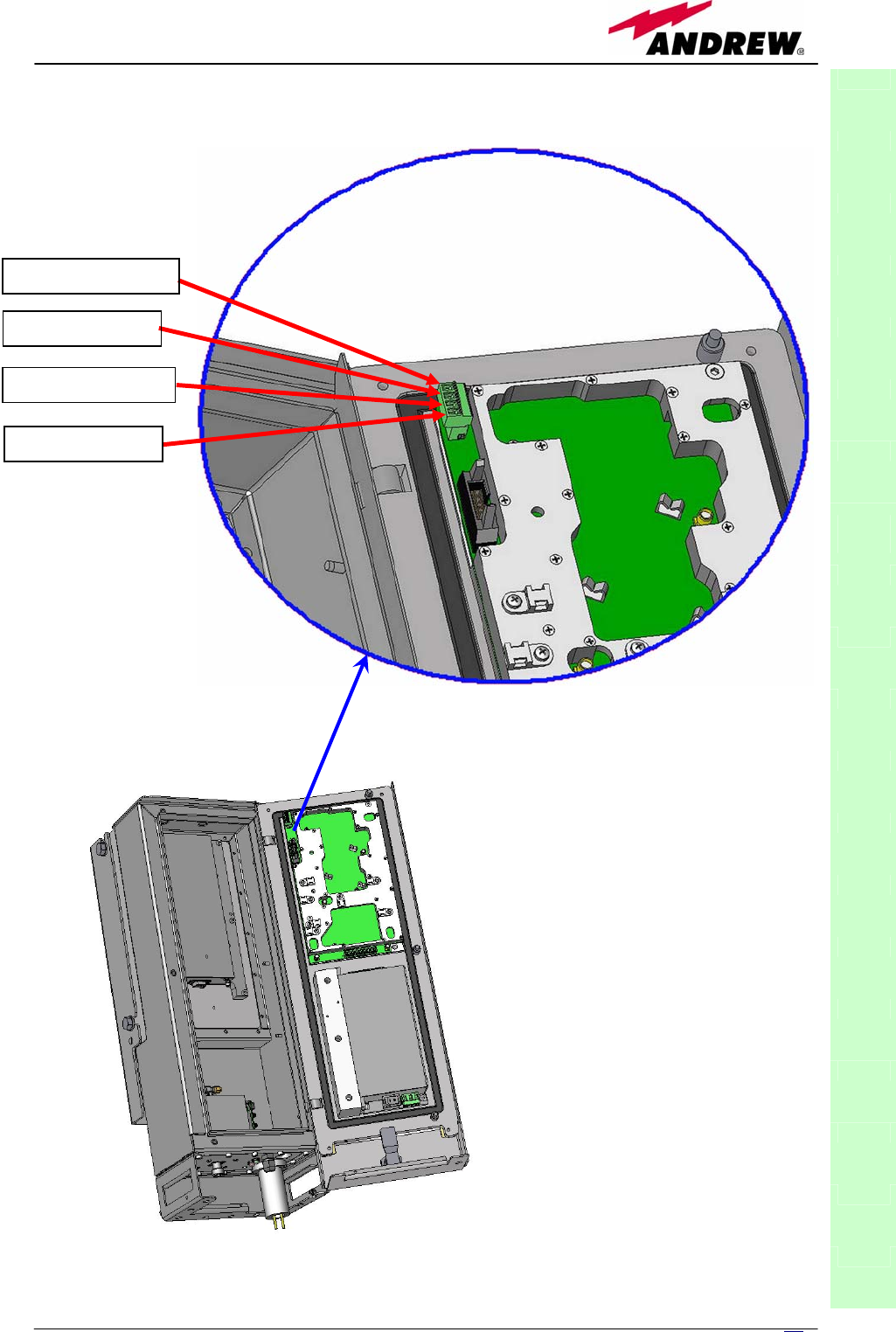
65
MN024-08
TFAx
CaseL
Pin 1: EXTERNAL 1
Pin 2: GROUND 1
Pin 3: EXTERNAL 2
Pin 4: GROUND 2
Fig. 3.30 : External alarm
contacts on Case F board

66 User Manual
Power supply:
The Case-L remote Unit is available in two versions: one feeded by universal
mains (85 to 265 Vac), the other by negative power supply (-72 to -36 Vdc):
in figure 3.31, the 85/220 Vac connector and the -72/-36 Vdc connector are
described. Power feeder is always internal. The power cable is always
included in the Case-L remote unit kit
Warnings (to be read before remote units are
installed)
Dealing with optical output ports
The Case-L remote unit contains semiconductor lasers. Invisible laser beams
may be emitted from the optical output ports. Do not look towards the optical
ports while equipment is switched on.
Choosing a proper installation site for the remote units
• Case-L remote units have to be installed as close as possible to the
radiating antennas, in order to minimize coaxial cable length, thus
reducing downlink power loss and uplink noise figure.
• When positioning the Case-L remote unit, pay attention that the placing of
related antennas should be decided in order to minimize the Minimum
Coupling Loss (MLC), so as to avoid blocking.
• The Case-L remote unit is intended to be fixed on walls or other flat
vertical surfaces.
Handling optical connections
• When inserting an optical connector, take care to handle it so smoothly
that the optical fibre is not damaged. Optical fibres are to be single-mode
(SM) 9.5/125µm.
TFAx
CaseL
(a)
85/264Vac Connector
PE: ground
1: N
2: L
PE
1 2
4
6
(b)
-36/-72Vdc Connector
4: 0V
6: -48V
Figure 3.31 : (a) 85/264 Vac and (b) -36/-72 Vdc connectors on a Case-L Remote Unit

6
7
MN024-08
• Typically, Britecell Plus equipment is provided with SC-APC optical
connectors (other connectors may be provided on request). Inserting any
other connectors will result in severe damages.
• Do not force or stretch the fibre pigtail with radius of curvature less than
5cm. See rightward figure for optimal fibre cabling.
• Remove the adapter caps only just before making connections. Do not
leave any SC-APC adapter open, as they attract dirt. Unused optical
connectors must always be covered with their caps.
• Do not touch the connector tip. Clean it with a proper tissue before
inserting each connector into the sleeve. In case connector tips need to be
cleaned, use pure ethyl alcohol.
TFAx Case-L installation
Each case-L Remote Unit kit includes:
• 1 Case-L Remote Unit;
• 1 key, required to open the Case-L connector cover
• 1 power supply cable (85 to 264 Vac or -48Vdc, depending on the power
supply which has been chosen);
• 1 pair of mounting plates;
• 1 screw kit, including four hexagonal-head screws and a torque key.
The operations which need to be carried out in order to perform a proper
installation of the Case-L Remote Unit are hereby described:
1- Take down the 2 mounting plates which are fixed to the case L (fig. 3.33a).
Fix the two mounting plates to the wall by firmly screwing the anchors.
2. Drill the wall to install four M8 screw anchors (not included) as indicated by
the installation drawing shown in fig. 3.33b.
3 –Take two of the hexagonal-head screws
included in the kit, and fasten them at the
top of the case-L unit (fig. 3.33c, step “1”)
by using the torque key: while fastening
the screws, take care to leave the space
required to hang the L-case to the plates.
Fasten the screws further only after
hanging the L-case. Then take the other
two hexagonal screws (included) and use
them to fasten the bottom sides of the
unit to the bottom side of the plates (see
fig. 3.33c, step “2”).
4 – Fix a splice holder (not included)
inside the proper splice tray (not included;
fig. 3.32). Makes the splices between the
fiberoptics patchcords coming from the
TFAx
CaseL
Fig. 3.32: (a) Splice tray. (b) Inside of the
splice tray, with the splice holder properly
positioned.

68 User Manual
Case-L remote unit and the fiberoptics cables which go to the local units.
House the optical splices inside the splice holder. Close the splice tray. During
these operations, please take care not to bend the fibres too much. Mount
the splice tray beside the remote unit.
5 -Turn the key which is provided in order to open the connector cover, and
remove the connector cover as in fig. 3.33e. If you need to use the Remote
Unit to control alarms on external devices, please refer to fig. 3.30 and to the
section “external alarms” in order to perform a proper cabling of the external
alarms connections.
6 - Loosen the four screws fixing the cover (fig. 3.33f), and take the cover
off. Unscrew the three screws indicated in fig. 3.33g, and open the unit
(3.33h).
7 - Connect the antenna RF cable to the RF antenna port (refer to fig. 3.33i).
In order to meet the IP65 compliance, please follow this procedure to carry
out the optical UL / DL connections. During these operations, take care not to
bend the fibers too much.
• Take off the PG13,5 Nut, the split-seal, the PG 13,5, and the pipe
connection.
• Make the optical patchcord pass through the PG 13,5 nut, the PG 13,5 and
the pipe connection. Connect the UL and DL optical connectors to the
corresponding UL and DL adapters the unit.
• Screw the pipe connection to the unit. Fasten the PG 13,5 to the pipe
connection.
• House the fiber optic cables (Ul and DL) on one half of the split-seal.
• Close the two halves of the split-seal, while paying attention not to stretch
the fibers.
• Insert the split-seal inside the PG13,5. Screw the PG 13,5 nut onto the PG
13,5.
8 - Connect the Power cable to the power connector. In case the power cable
has been connected to the mains, both the green and the red LEDs should
turn on. The green LED will remain on to indicate that the unit is powered on,
while the RED led will turn off as soon as the local unit will be switched on
(for further details about the start-up of the whole system, please refer to the
section ”TFAx Case L start-up”).
9 - Close the cover, and fasten the 3 screws indicated in fig. 3.33g. Fasten
the 4 screws indicated in fig. 3.33f. Mount both the external cover and the
connector cover. Turn the key to close the connector cover.
TFAx Case-L start-up
Before the Case-L remote unit is switched on, make sure that:
• the modules hosted in the master unit have been connected each other
with RF jumpers, according to the system design
• every TFLN master optical TRX has been connected to its remote units
• each remote unit has been connected to its coverage antennas
TFAx
CaseL

69
MN024-08
For a correct system start-up, all the remote units have to be switched
on before the master unit.
Once the Case-L Remote Unit has been switched on, its behaviour could be
checked by turning the key, removing the connector cover, and looking at the
control LEDs. When the system starts-up, their status can be summarised as
per the following steps.
1. When the remote unit is turned on, both the LEDs turn on for a
couple of seconds.
2. After that, the unit green LED remains on (thus indicating proper
power supply), while the red LED switches off as soon as the TFLN
master unit is turned on (meaning that DL optical power is OK and
no alarms are present).
3. Once the TFLN master unit has been switched on, the status of both
LEDs have to be the one reported in table 3.7 In case the red LED
remains on, please refer to the troubleshooting section.
4. Once it has been switched on, the remote unit starts working
correctly. Anyway, in order to be recognized by the supervision
management system, it is necessary for the corresponding TFLN
master optical TRX to carry out the discovery phase (please refer to
Supervision System Manual for more details). During this phase,
(whose duration depends on the system complexity, and which can
last at max. 4min) the TFLN LED ┌┘ blinks. Do not
connect/disconnect any cable or any piece of equipment
during the discovery phase! This may result in no identification
of the remote unit.
Note: if then discovery doesn’t start automatically, check through the LMT
or the remote supervision whether it has been disabled (refer to LMT or
remote supervision system manuals for further information).
TFAx Case-L troubleshooting
Faults can be revealed by LEDs on the Case L front panel as well as by the
LMT software or the TSUN supervision system.
Both the LMT software and the TSUN supervision interface provide full
information about the device causing the alarm. As a consequence,
troubleshooting procedure can be very immediate when the failure detection is
directly carried out through the LMT software or the supervision system.
Britecell Plus modules are designed in order to exchange information each
other: each remote unit can receive failure notifications from their external
equipment through dry-contact connections. Moreover, each TFAx constantly
monitors the optical signal received from its TFLN unit, so as to control optical
losses.
Table 3.8 shows a brief description of the alarms related to a Case L remote
unit, with a reference to the corresponding alerted LEDs and to the actions to
be carried out in the case of a fault.
TFAx
CaseL
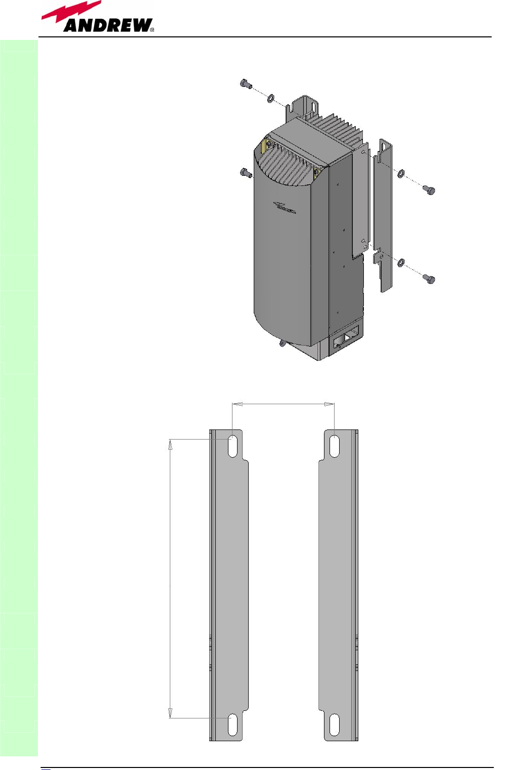
70 User Manual
TFAx
CaseL
Fig. 3.33 (a): Side plates to
be taken down from the
case L remote unit
150
356,50
Fig. 3.33 (b):
Layout for the
installation of the
case L remote unit
plates
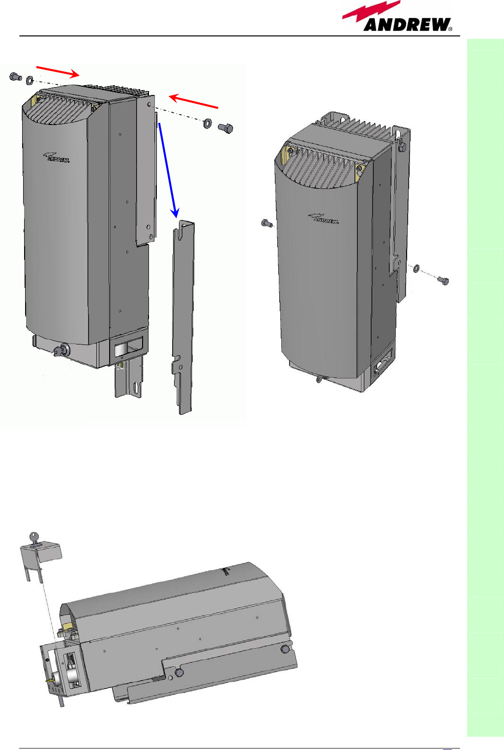
71
MN024-08
TFAx
CaseL
1
1
2
Fig. 3.33 (c): When fastening the upper screws
(1), leave the space required in order to hang the
case (2) to the plates which have just been fixed
to the wall
Fig. 3.33 (d): After hanging the case to the
p
lates fixed to the walls, fasten the lower
screws.
Fig. 3.33 (e): Open the
connector cover
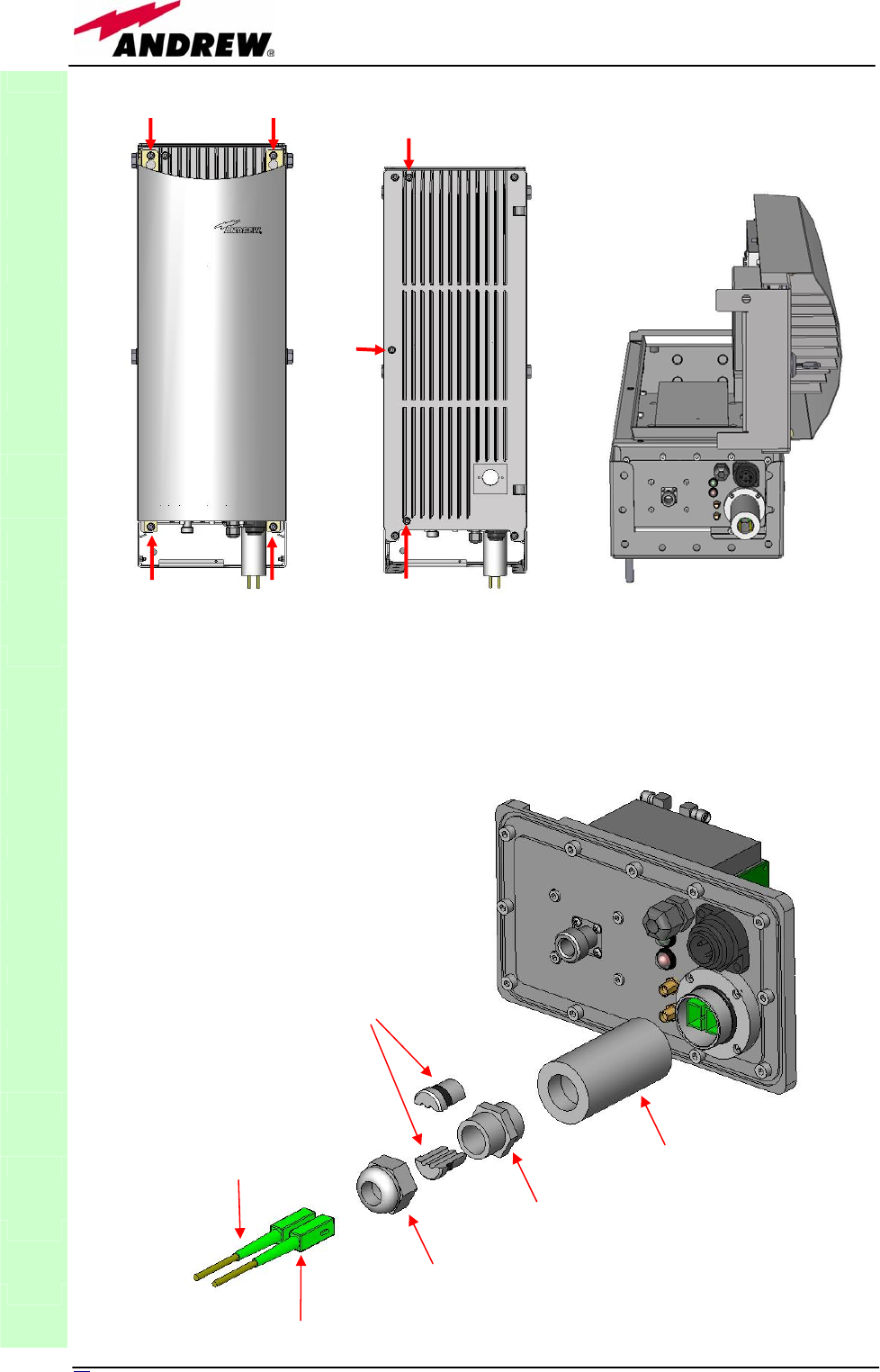
72 User Manual
TFAx
CaseL
Fig. 3.33 (f): loosen
the four screws and
remove the external
cover
Fig. 3.33 (g): after
removing the external
cover, loosen the
three screws
Fig. 3.33 (h): open
the cover of TFAx
Case
-
L
Split-seal
PG13,5-Nut
PG13,5
pipe connection
Optical DL
Optical UL
Fig. 3.33 (i): Detail of theUL / DL optical
connections meeting IP65 requirements.

73
MN024-08
ALARM
CODE
(TSUN
description)
ALARM
DESCRIPTION
ACTIVE
LED
SUPERVISION
PRIORITY
LEVEL
ACTION
RECOMMENDED
RELÉ
PRIORITY
LEVEL
(subrack)
DL optical power
The DL received
optical power is too
low and can no more
be compensated by
AGC 1
RED MAJOR
Check the DL fibre
and the TFLN laser
status MAJOR
AGC out of
range
The DL received
optical power
experiences a loss >
3dB, which
nevertheless can still
be compensated 1
NONE WARNING
Clean optical
connectors MINOR
External 1 alarm Alarm on the device
connected on dry-
contact 1 RED MAJOR
Check the external
device or alarm
connection MAJOR
External 2 alarm Alarm on the device
connected on dry-
contact 2 RED MAJOR
Check the external
device or alarm
connection MAJOR
Power supply
alarm
UPS HW failure or
malfunction.
RF is turned OFF RED MAJOR
Check the external
PSU. If it works
properly, return the
unit
MAJOR
Internal BUS
alarm
A malfunctioning on
the digital part involves
a fault in monitoring
functionalities
RED CRITICAL Return the unit MAJOR
Temperature
alarm Over-temperature
alarm NONE MINOR
Check ventilation
and environment MINOR
DL UMTS band
alarm
HW failure on the DL
UMTS band RF
section RED CRITICAL Return the unit MAJOR
As table shows, not all the alarms are revealed by the LEDs placed on the
remote unit control panel: in fact, LEDs reveal only major alarms (i.e., the
high priority ones), whereas the minor alarms (i.e., the low priority ones) are
revealed only by the LMT software or through the TSUN supervision system.
The minor alarms usually detect critical situations which should be checked so
as to avoid future possible system faults.
1Note:
Each remote unit is provided with an AGC system which comes in after the optical-to-RF
conversion. This AGC can correctly compensate optical losses when these are estimated to be
<3 dB. In case optical losses are in the 3dB- 4dB range, the AGC is said to be “out of range”:
the whole system still work, but AGC is near to its borderline levels. The DL power LED switches
on when the estimated optical losses are >4dB, the AGC not being able to compensate these
losses any more.
As shown in the previous table, the same red LED switches on to reveal any major failure.
Following the troubleshooting procedure reported hereinafter it is possible to better understand
what problem occurred.
Quick troubleshooting procedure
(The following procedure is summarized by the flow-chart in fig. 3.34a)
In case the red LED is ON, please follow these steps:
TFAx
CaseL
Table 3.8: Description of the alarms of the TFAN Case-B Remote
Unit, as they are presented on LMT or Supervision Interface

74 User Manual
5. First of all, refer to external alarm troubleshooting in order to understand
whether the alarm can depend on any external equipment failure or not.
6. In case external alarm troubleshooting has not revealed any failure, clean
the optical adapters
7. If the problem still persists, refer to the fibre optic DL troubleshooting to
check if optical cables or optical connections have any problem on DL path.
8. If previous actions didn’t make the LED switch off replace the unit with a
new one or contact for assistance.
External-alarm troubleshooting
(The following procedure is summarized by the flow-chart in fig. 3.34b)
This procedure needs to be considered if at least one external alarm terminal
is connected to some external equipment (see section “external alarms”). If
not, return to main troubleshooting procedure.
These steps aim to detect any failure inside the external equipment or inside
the external alarm terminal. If the external alarm terminals don’t reveal any
equipment malfunction or any terminal failure, return to the main
troubleshooting procedure.
For any external alarm terminal connected to some external equipment,
follow these steps:
4. Disconnect it, and check the TFAx LED status after the disconnection.
5. If the red LED has switched off, external equipment connected to the
alarm terminal should be faulty. Please test it.
6. If the TFAx red LED still remains on after the disconnection, measure the
voltage between the poles of the alarm terminal.
c. If the poles of the alarm terminal are electrically closed, the circuit
board should have any problem. Contact the manufacturer for
assistance.
d. If the poles of the alarm terminal are open, this means neither the
analysis of this alarm terminal nor the one of its external
equipment has revealed any failure. Re-connect this alarm terminal
to its external equipment. In case the TFAx has another alarm
terminal connected to some external equipment and still to be
checked, apply the whole procedure (i.e,, the steps 1-3) to this still
unchecked terminal.
Fibre optic DL troubleshooting
(The following procedure is summarized by the flow-chart in fig. 3.34c)
1. Check if there is any point where fibre experiences a short radius of
curvature. In this case, rearrange the optical path in order to avoid
sharp bends (if necessary, replace the optical cable with a longer one). If
TFLN red LED switches off, troubleshooting has been successfully carried
out. Otherwise, follow next steps.
2. Check if SC-APC connectors are properly installed at both fibre ends. In
case they are not, fix better SC-SPC connectors to adapters. If TFLN red
LED switches off, troubleshooting has been successful. Otherwise, follow
next steps.
3. Disconnect the optical fibre and clean it better at both ends then clean
the SC-APC ports on both the TFLN and the remote unit. Re-connect the
TFAx
CaseL
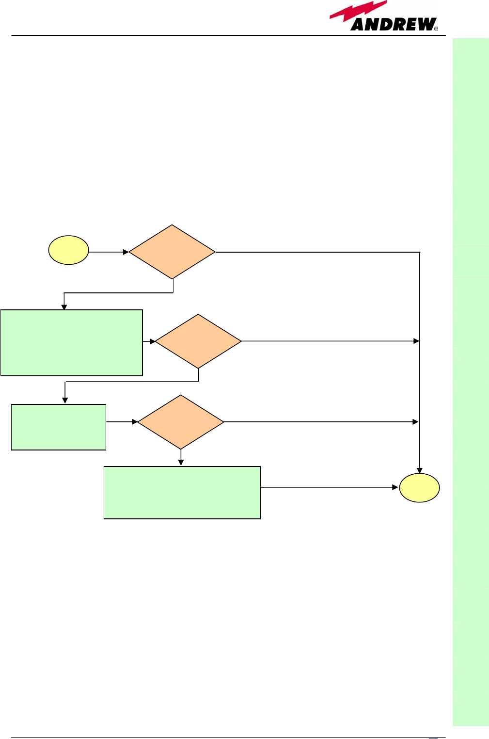
75
MN024-08
fibre to relevant ports after cleaning. If it doesn’t made TFLN red LED
switch off, follow next steps.
4. Disconnect the optical SC-APC connector from remote unit DL port, and
measure the output power POUT(DL) at the corresponding fibre end. Then,
go to the TFLN side, disconnect the optical SC-APC connector from TFLN
DL port and measure the input power PIN(DL) coming out of the TFLN DL
port. Calculate the DL fibre attenuation ADL as ADL [dB] = PIN(DL) –
POUT(DL)
c. If ADL > 4dB, then the fibre optic cable has some problems. Replace it
with a new one.
d. If ADL < 4dB troubleshooting procedure has not identified the problem.
Refer to supervision system or contact assistance.
TFAx
CaseL
Fig. 3.34a: Flow-chart describing the quick troubleshooting procedure on Case LTFAx
star
t
Is the red LED
ON upon the
TFAx?
No
Yes
Yes
N
o
Verify if any external equipment
or any external alarm terminal
has some problems. Refer to
external alarm troubleshooting
(fig.3.34b)
Clean the SC-APC
optical adapters and
connectors
N
o
Yes
end
Is red LED upon
TFAx still ON?
Is red LED upon
TFAx still ON?
Optical cable or optical connections
are supposed to have problems on
DL path. Refer to fibre optic DL
troubleshooting (fig. 3.34c)
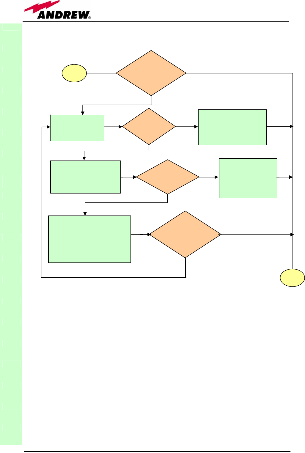
76 User Manual
TFAx
CaseL
Picture. 3.34b: Flow-chart describing the external alarm troubleshooting on Case L TFAx
start
Is any
external alarm
terminal connected to
some equipment?
No
Yes
Disconnect the
external alarm
terminal
Is red LED
upon TFAx
still ON?
No
External equipment
connected to this
external alarm terminal
should be faulty. Test it.
Yes
Measure voltage between
the two poles of this
external alarm terminal
Is terminal
electrically closed?
The circuit board
should have some
problems. Contact
the manufacturer
for assistance.
Yes
The analisys on this alarm
terminal and its external
equipment has not revealed
any failure.
Re-connect this alarm terminal
to its external equipment.
Is the
other external alarm
terminal connected to
some equipment?
No
Yes
No
end
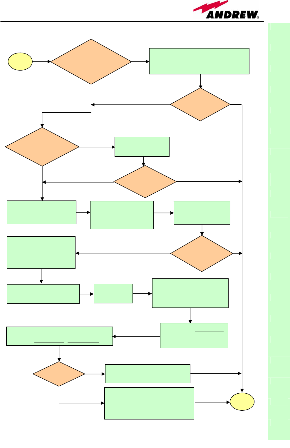
77
MN024-08
TFAx
CaseL
Fig. 3.34c: Flow-chart describing the fibre optic DL troubleshooting
start
Is there any
point where the
fibre experiences
a small radius of
curvature?
Rearrange the optical path to avoid
sharp bends. If necessary replace the
optical cable with a longer one.
Is the red LED
upon the TFAx
still ON?
Are SC-APC
connectors properly
installed at both fibre
ends?
Fix better SC-APC
connectors
Yes
N
o
N
o
Y
es
No
Y
es
N
o
Y
es
Disconnect the optical
SC-APC connector from
remote unit DL port
Clean optical SC-APC
ports on both TFL
N
and remote uni
t
.
Disconnect fibre optic
and clean it at both ends.
Reconnect the fibre
to relevant ports
Measure the output power
at corresponding fibre end.
Measure the input power
coming out of the TFLN
DL port.
Disconnect optical SC-APC
connector from TFLN DL
port.
Calculate DL fibre attenuation
ADL[dB]=input power - output power
Is ADL > 4dB? Fibre optic cable has some
problems. Replace it.
Troubleshooting procedure has
not identified the problem. Refer
to supervision system or contact
assistance
end
N
o
Y
es
No
Y
es
is the red LED
upon TFAx
still ON?
Is red LED
upon remote
unit still ON?
Go to TFLN
side.

78 User Manual
TFAx
CaseL
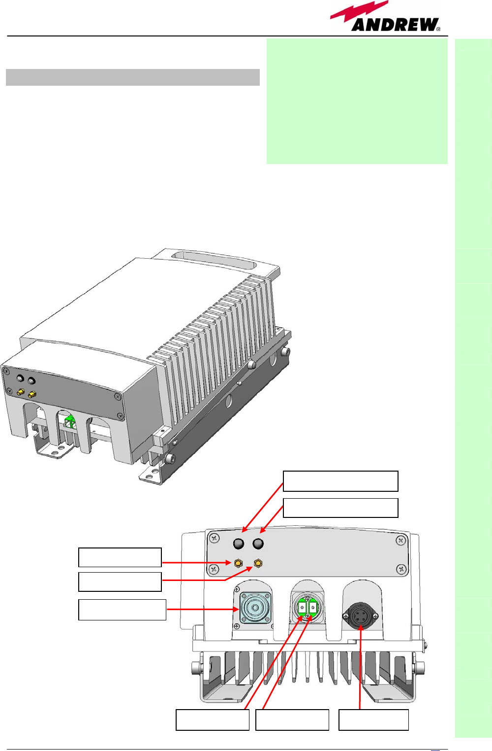
79
MN024-08
3.5. Case F remote unit
Dimensions and Weight
Dimensions: mm. 564 x 255 x 167
(inches 21.5 x 10 x 8.1)
Weight: please refer to the Britecell
Plus bulletin PA-100595EN or to the remote unit dedicated
bulletin in order to know the updated data about the weight
of your case-F remote unit.
TFAx
CaseF
Fig. 3.35: (a) Case F
remote unit ;
(b) connection panel of
the Case F remote unit
Module name:
Remote Unit
TFAH
Case F
(b)
GREEN LED = power on
RED LED = major alarm
DL aux RF
p
ort
UL aux RF
p
ort
RF antenna port
DL optical port UL optical port Power supply
(a)
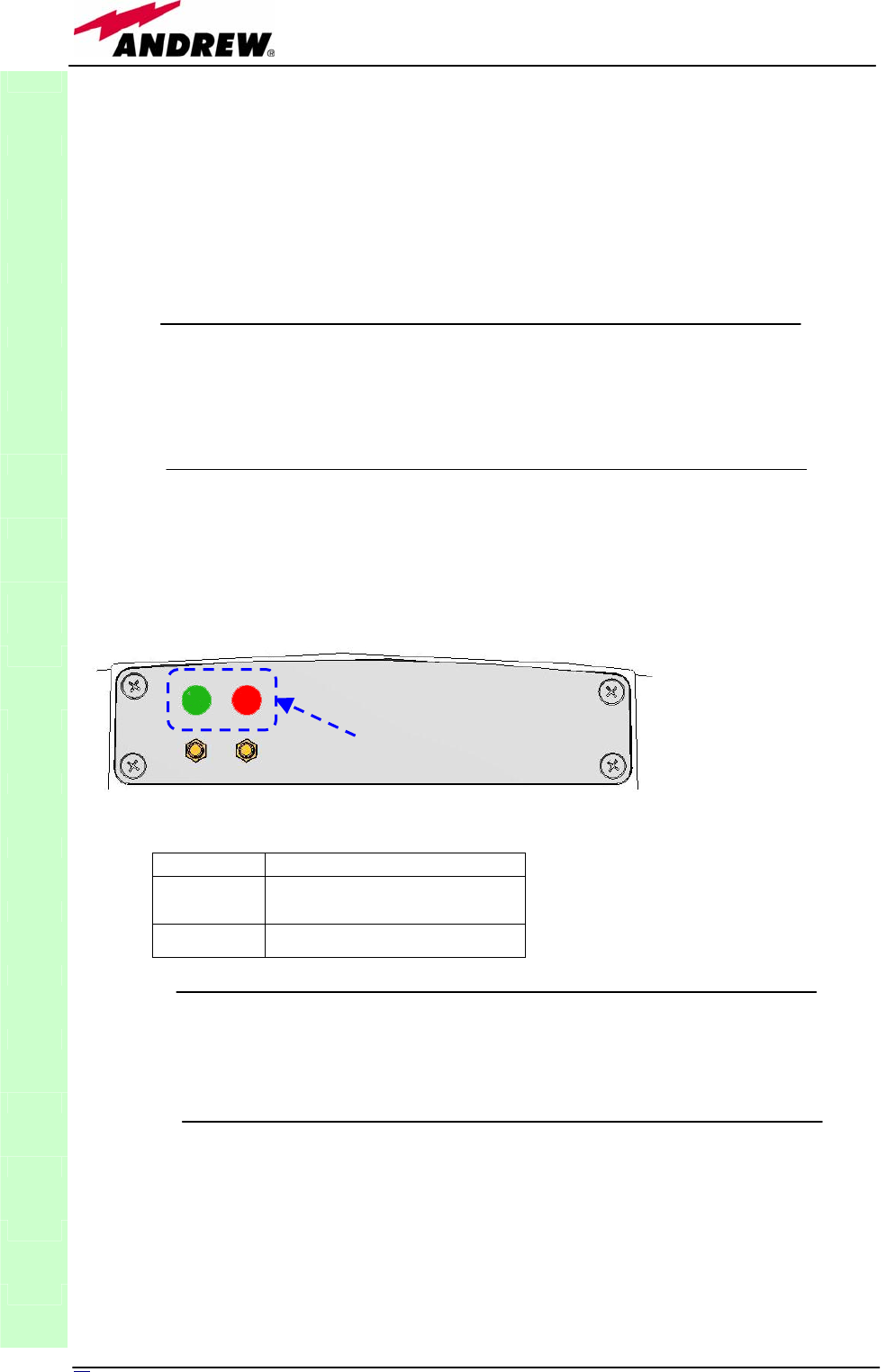
80 User Manual
RF ports:
Optical ports:
Visual alarms:
Two control LEDs are provided on the Case-F upper side (fig. 3.36).
The green LED describes the power supply status, while the red LED describes
the major Remote Unit failures (fig. 3.9).
External alarms
Case F architecture does not provide any external alarms control.
Power supply:
Case-F remote Unit is available in two versions: one feeded by universal
mains (85 to 265 Vac), the other by negative power supply (-72 to -36 Vdc):
in figure 3.37, the 85/220 Vac connector and the -72/-36 Vdc connector are
described. Power feeder is always internal. The power cable is always
included in the Case-F remote unit kit.
TFAx
CaseF
Led colour Meaning
Red Low optical power at DL input
and/or RF amplifier failure
Green Power supply OK
Table 3.9: summary of Case F
LEDs meaning
• 1 RF antenna port, transmitting/receiving signals to/from
distributed antennas. This RF antenna port is a duplexed
N-female connectors. The port can be connected to the
antenna either directly (ie. through RF jumper cables) or
through splitters, thus allowing more antennas to be fed.
• 1 RF auxiliary input and 1 RF auxiliary output (designed to
receive and transmit additional signals). Auxiliary input
and output ports are SMA-female connectors.
• 1 optical output port, transmitting UL signals to TFLN
master optical TRX;
• 1 optical input port, receiving DL signals from TFLN
master optical TRX.
Fig. 3.36 : LED panel on
the Case
F
warm side

81
MN024-08
Warnings (to be read before remote units are installed)
Dealing with optical output ports
The Case-F remote unit contains semiconductor lasers. Invisible laser beams
may be emitted from the optical output ports. Do not look towards the optical
ports while equipment is switched on.
Choosing a proper installation site for the remote units
• Case-F remote units have to be installed as close as possible to the
radiating antennas, in order to minimize coaxial cable length, thus reducing
downlink power loss and uplink noise figure.
• When positioning the Case-F remote unit, pay attention that the placing of
related antennas should be decided in order to minimize the Minimum
Coupling Loss (MLC), so as to avoid blocking.
• The Case-F remote unit is intended to be fixed on walls or other flat vertical
surfaces.
Handling optical connections
• When inserting an optical connector, take care to handle it so smoothly
that the optical fibre is not damaged. Optical fibres are to be single-mode
(SM) 9.5/125µm.
• Typically, Britecell Plus equipment is provided with SC-APC optical
connectors (other connectors may be provided on request). Inserting any
other connectors will result in severe damages.
• Do not force or stretch the fibre pigtail with radius of curvature less than
5cm. See rightward figure for optimal fibre cabling.
• Remove the adapter caps only just before making connections. Do not
leave any SC-APC adapter open, as they attract dirt. Unused optical
connectors must always be covered with their caps.
• Do not touch the connector tip. Clean it with a proper tissue before
inserting each connector into the sleeve. In case connector tips need to be
cleaned, use pure ethyl alcohol.
TFAx
CaseF
Figure 3.37 : (a) 85/264 Vac and (b) -36/-72 Vdc connectors on a Case-F Remote Unit
(a)
85/264Vac Connector
PE: ground
1: N
2: L
PE
1 2
4
6
(b)
-36/-72Vdc Connector
4: 0V
6: -48V
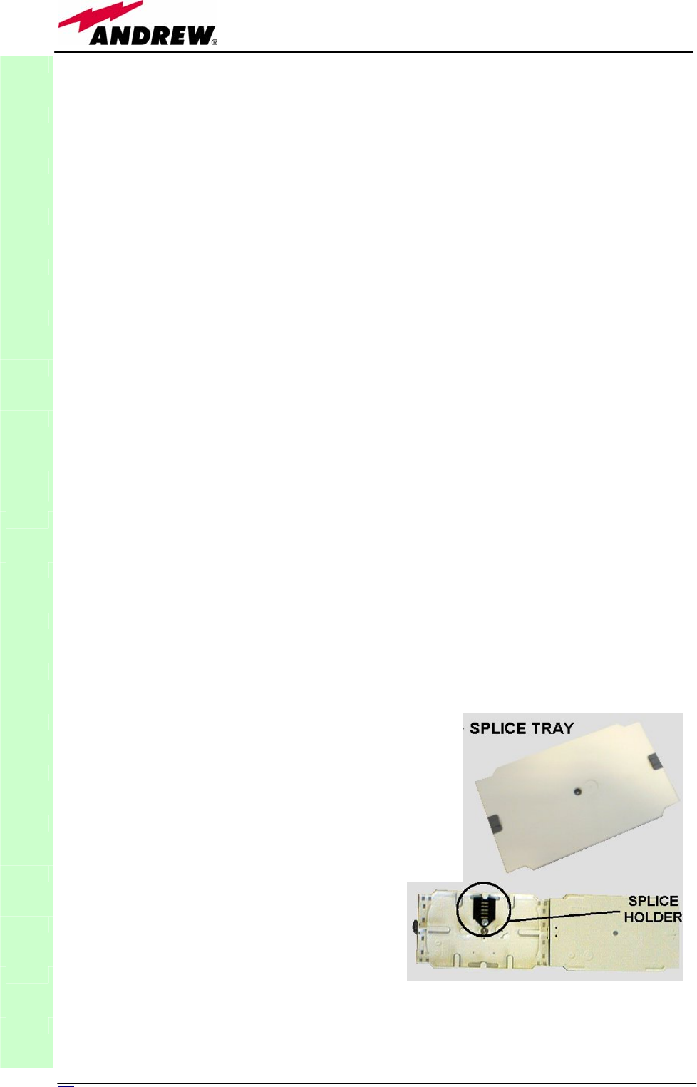
82 User Manual
TFAx Case-F installation
Each case-F Remote Unit kit includes:
• 1 Case-F Remote Unit;
• 1 power supply cable (85 to 264 Vac or -48Vdc, depending on the power
supply which has been chosen);
• 1 pair of mounting plates;
• 1 screw kit, including four hexagonal-head screws and a torque key.
The operations which need to be carried out in order to perform a proper
installation of the Case-F Remote Unit are hereby described:
1- Drill the wall to install four M8 screws anchors (not included) as indicated
by the installation drawing shown in fig. 3.39a. Fix the two mounting plates to
the wall by firmly screwing the anchors.
2 –Take two of the hexagonal-head screws included in the kit, and fasten
them at the top of the case-F unit (fig. 3.39b, step “1”) by using the torque
key: while fastening the screws, take care to leave the space required to
hang the case-F to the plates (fig. 3.39b, step “2”).. Fasten the screws
further only after hanging the case-F. Then take the other two hexagonal
screws (included) and use them to fasten the bottom sides of the unit to the
bottom side of the plates (fig. 3.39b, step “3”).
3 – Fix a splice holder (not included) inside the proper splice tray (not
included, fig. 3.38). Makes the splices between the fiberoptics patchcords
coming from the Case-F remote unit and the fiberoptics cables which go to
the local units. House the optical splices inside the splice holder. Close the
splice tray. During these operations, please take care not to bend the fibres
too much. Fix the splice tray inside a splice box (not included), and mount
the splice box beside the remote unit.
4 - Use the torque key in order to loose
the four screws fixing the cover (fig.
3.39c), and open the unit.
Connect the antenna RF cable to the RF
antenna port. Connect the UL and DL
optical connectors to the corresponding
UL and DL adapters on the unit.
Connect the Power cable to the power
connector. In case the power cable has
been connected to the mains, both the
green and the red LEDs should turn on.
The green LED will remain on to indicate
that the unit is powered on, while the
RED led will turn off as soon as the local
unit will be switched on (for further
details about the start-up of the whole
system, please refer to the section ”TFAx
TFAx
CaseF
Fig. 3.38: (a) Splice tray. (b) Inside of the
splice tray, with the splice holder properly
positioned.
(
a
)
(
b
)

83
MN024-08
Case F start-up”).
5 - Close the unit, and fasten the 4 screws indicated in fig. 3.39c by using the
torque key.
TFAx Case F start-up
Before the Case-F remote unit is switched on, make sure that:
• the modules hosted in the master unit have been connected each other
with RF jumpers, according to the system design
• every TFLN master optical TRX has been connected to its remote units
• each remote unit has been connected to its coverage antennas
For a correct system start-up, all the remote units have to be switched
on before the master unit.
Once the Case-F Remote Unit has been switched on, its behaviour could be
checked by unscrewing the four hexagonal screws (see fig on the sides of the
case-F), removing the cover, and looking at the control LEDs. When the
system starts-up, their status can be summarised as per the following steps.
1. When the remote unit is turned on, both the LEDs turn on for a couple
of seconds.
2. After that, the unit green LED remains on (thus indicating proper power
supply), while the red LED switches off as soon as the TFLN master unit
is turned on (meaning that DL optical power is OK and no alarms are
present).
3. Once the TFLN master unit has been switched on, the status of both
LEDs have to be the one reported in table 3.9. If the red LED remains
on, please refer to the troubleshooting section.
4. Once it has been switched on, the remote unit starts working correctly.
Anyway, in order to be recognized by the supervision management
system, it is necessary for the corresponding TFLN master optical TRX
to carry out the discovery phase (please refer to Supervision System
Manual for more details). During this phase, (whose duration depends
on the system complexity, and which can last at max. 4min) the TFLN
LED ┌┘ blinks. Do not connect/disconnect any cable or any piece
of equipment during the discovery phase! This may result in no
identification of the remote unit.
Note: if then discovery doesn’t start automatically, check through the LMT or
the remote supervision whether it has been disabled (refer to LMT or remote
supervision system manuals for further information).
TFAx
CaseF
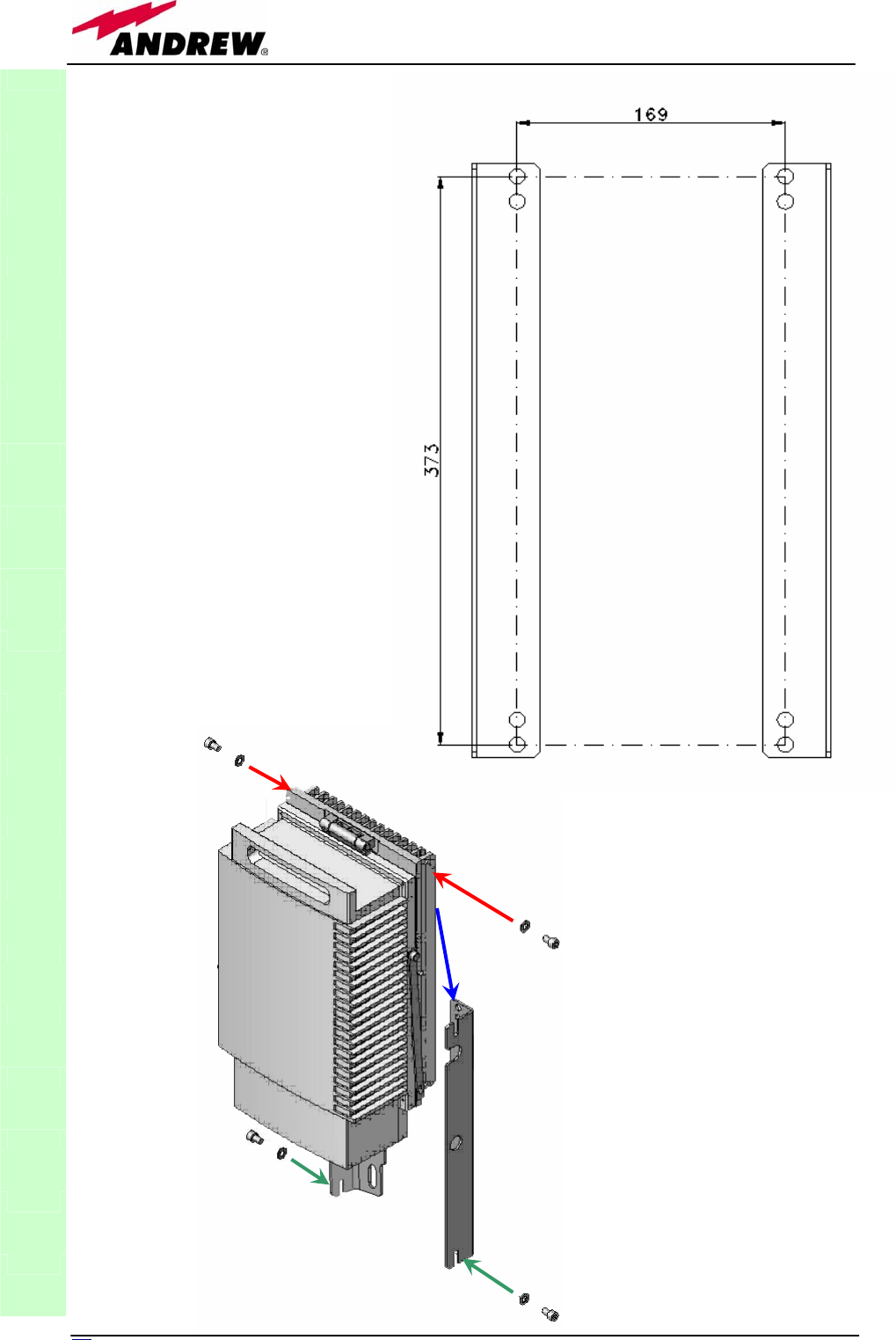
84 User Manual
TFAx
CaseF
Fig. 3.39 (a) : layout for
the installation of the
Case F plates
Fig. 3.39 (b) : while fastening
the two hexagonal screws to
the top of the case (step “2”),
take care to leave the space
required to hang the case to
the plates (step “2”) Then
fasten the other two
hexagonal screws to the
bottom of the case
(
ste
p
“3”
)
1
1
2
3
3
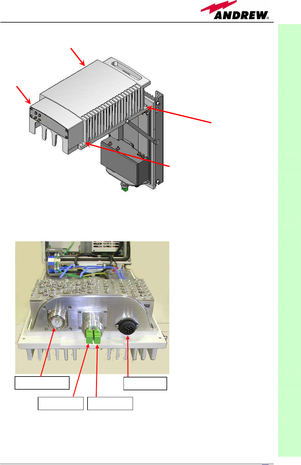
85
MN024-08
TFAx
CaseF
RF antenna port
DL optical port UL optical port
Power supply
Fig. 3.39 (c) : loose the
four screws fixing the
cover and open the unit
Fig. 3.39 (d) :
p
ower
supply, optical and RF
connections on the
TFAx Case F

86 User Manual
TFAx Case F troubleshooting
Faults can be revealed by LEDs on the Remote Unit (RU) front panel as well
as by LMT or supervision system (running on the remote supervision unit)
Both LMT and supervision system provide full information about the device
causing the alarm. As a consequence, troubleshooting procedure can be very
immediate when the failure detection is directly carried out through LMT or
supervision system.
Britecell Plus modules are designed in order to exchange information each
other: each RU constantly monitors the optical signal received from its TFLN
unit, so as to control optical losses.
Table 3.8 shows a brief description of the alarms related to a Case L remote
unit, with a reference to the corresponding alerted LEDs and to the actions to
be carried out in the case of a fault.
As table shows, not all the alarms are revealed by the LEDs placed on the
remote unit control panel: in fact, LEDs reveal only major alarms (i.e., the
high priority ones), whereas the minor alarms (i.e., the low priority ones) are
revealed only by the LMT software or through the TSUN supervision system.
The minor alarms usually detect critical situations which should be checked so
as to avoid future possible system faults.
1Note:
TFAx
CaseF
ALARM CODE
(TSUN
description)
ALARM
DESCRIPTION
ACTIVE
LED
SUPERVISION
PRIORITY
LEVEL
ACTION
RECOMMENDE
D
RELÉ
PRIORITY
LEVEL
(subrack)
DL optical power
The DL received
optical power is too
low and can no more
be compensated by
AGC 1
RED MAJOR
Check the DL fibre
and the TFLN laser
status MAJOR
AGC out of range
The DL received
optical power
experiences a loss >
3dB, which
nevertheless can still
be compensated 1
NONE WARNING
Clean optical
connectors MINOR
DL low band alarm
(not implemented
on TFAH 19)
HW failure on the DL
RF low band RED CRITICAL Return the unit MAJOR
DL high band alarm
(not implemented
on TFAH 80 and
TFAH 85)
HW failure on the UL
RF low band RED CRITICAL Return the unit MAJOR
Power supply alarm UPS HW failure or
malfunction.
RF is turned OFF RED MAJOR Return the unit MAJOR
Internal BUS alarm
A malfunctioning on
the digital part involves
a fault in monitoring
functionalities
RED CRITICAL Return the unit MAJOR
Temperature alarm Over-temperature
alarm NONE MINOR
Check ventilation
and environment MINOR
Table 3.10. Description of the alarmi of the TFAx Case F Remote Unit, as they are
presented on LMT or Supervision Interface

87
MN024-08
Each remote unit is provided with an AGC system which comes in after the optical-to-RF
conversion. This AGC can correctly compensate optical losses when these are estimated to be
<3 dB. In case optical losses are in the 3dB- 4dB range, the AGC is said to be “out of range”:
the whole system still work, but AGC is near to its borderline levels. The DL power LED switches
on when the estimated optical losses are >4dB, the AGC not being able to compensate these
losses any more.
As shown in the previous table, the same red LED switches on to reveal any major failure.
Following the troubleshooting procedure reported hereinafter it is possible to better understand
what problem occurred.
Quick troubleshooting procedure
(The following procedure is summarized by the flow-chart in fig. 3.40a)
In case the red LED is ON, please follow these steps:
1. First of all, clean the optical adapters
2. If the problem still persists, refer to the fibre optic DL troubleshooting to
check if optical cables or optical connections have any problem on DL path.
3. If previous actions didn’t make the LED switch off replace the unit with a
new one or contact for assistance.
Fibre optic DL troubleshooting
(The following procedure is summarized by the flow-chart in fig. 3.40b)
1. Check if there is any point where fibre experiences a short radius of
curvature. In this case, rearrange the optical path in order to avoid sharp
bends (if necessary, replace the optical cable with a longer one). If TFLN red
LED switches off, troubleshooting has been successfully carried out.
Otherwise, follow next steps.
2. Check if SC-APC connectors are properly installed at both fibre ends. In
case they are not, fix better SC-SPC connectors to adapters. If TFLN red
LED switches off, troubleshooting has been successful. Otherwise, follow
next steps.
3. Disconnect the optical fibre and clean it better at both ends then clean the
SC-APC ports on both the TFLN and the remote unit. Re-connect the fibre to
relevant ports after cleaning. If it doesn’t made TFLN red LED switch off,
follow next steps.
4. Disconnect the optical SC-APC connector from remote unit DL port, and
measure the output power POUT(DL) at the corresponding fibre end. Then,
go to the TFLN side, disconnect the optical SC-APC connector from TFLN DL
port and measure the input power PIN(DL) coming out of the TFLN DL port.
Calculate the DL fibre attenuation ADL as ADL [dB] = PIN(DL) – POUT(DL)
a. If ADL > 4dB, then the fibre optic cable has some problems. Replace it
with a new one.
b. If ADL < 4dB troubleshooting procedure has not identified the problem.
Refer to supervision system or contact assistance.
TFAx
CaseF
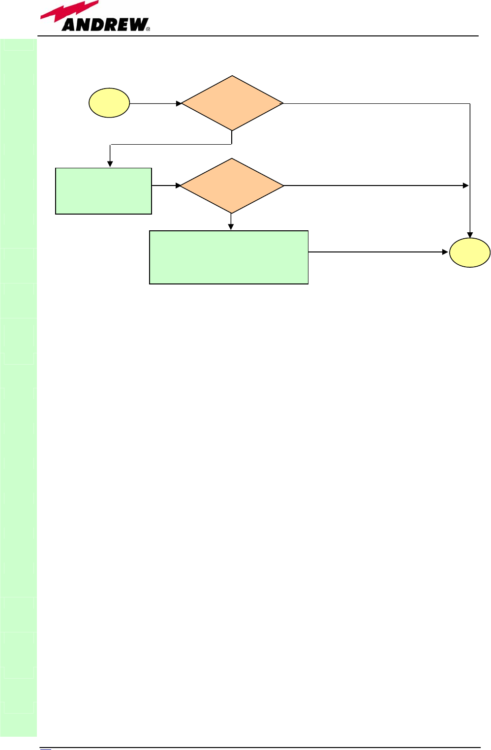
88 User Manual
TFAx
CaseF
Picture. 3.40(a): Flow-chart describing the quick troubleshooting procedure on Case F TFAx
start
Is the
red LED ON
upon the TFAx?
Yes
N
o
Clean the SC-APC
optical adapters and
connectors
N
o
Yes
end
Is the red LED
upon the TFAx
still ON?
Optical cable or optical connections
are supposed to have problems on
DL path. Refer to fibre optic DL
troubleshooting (fig. 3.40b)
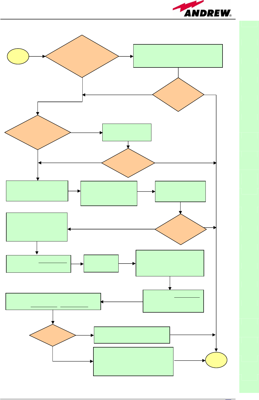
89
MN024-08
TFAx
CaseF
Fig. 3.40(b): Flow-chart describing the fibre optic DL troubleshooting
start
Is there any
point where the
fibre experiences
a small radius of
curvature?
Rearrange the optical path to avoid
sharp bends. If necessary replace the
optical cable with a longer one.
Is the red LED
upon the TFAx
still ON?
Are SC-APC
connectors properly
installed at both fibre
ends?
Fix better SC-APC
connectors
Yes
N
o
N
o
Y
es
No
Y
es
N
o
Y
es
Disconnect the optical
SC-APC connector from
remote unit DL port
Clean optical SC-APC
ports on both TFL
N
and remote uni
t
.
Disconnect fibre optic
and clean it at both ends.
Reconnect the fibre
to relevant ports
Measure the output power
at corresponding fibre end.
Measure the input power
coming out of the TFLN
DL port.
Disconnect optical SC-APC
connector from TFLN DL
port.
Calculate DL fibre attenuation
ADL[dB]=input power - output power
Is ADL > 4dB? Fibre optic cable has some
problems. Replace it.
Troubleshooting procedure has
not identified the problem. Refer
to supervision system or contact
assistance
end
No
Y
es
No
Y
es
Is the red LED
upon the TFAx
still ON?
Is the red LED
upon the TFAx
still ON?
Go to TFLN
side.

90 User Manual
3.6. Wi-Fi Booster TFBWx
TFBW
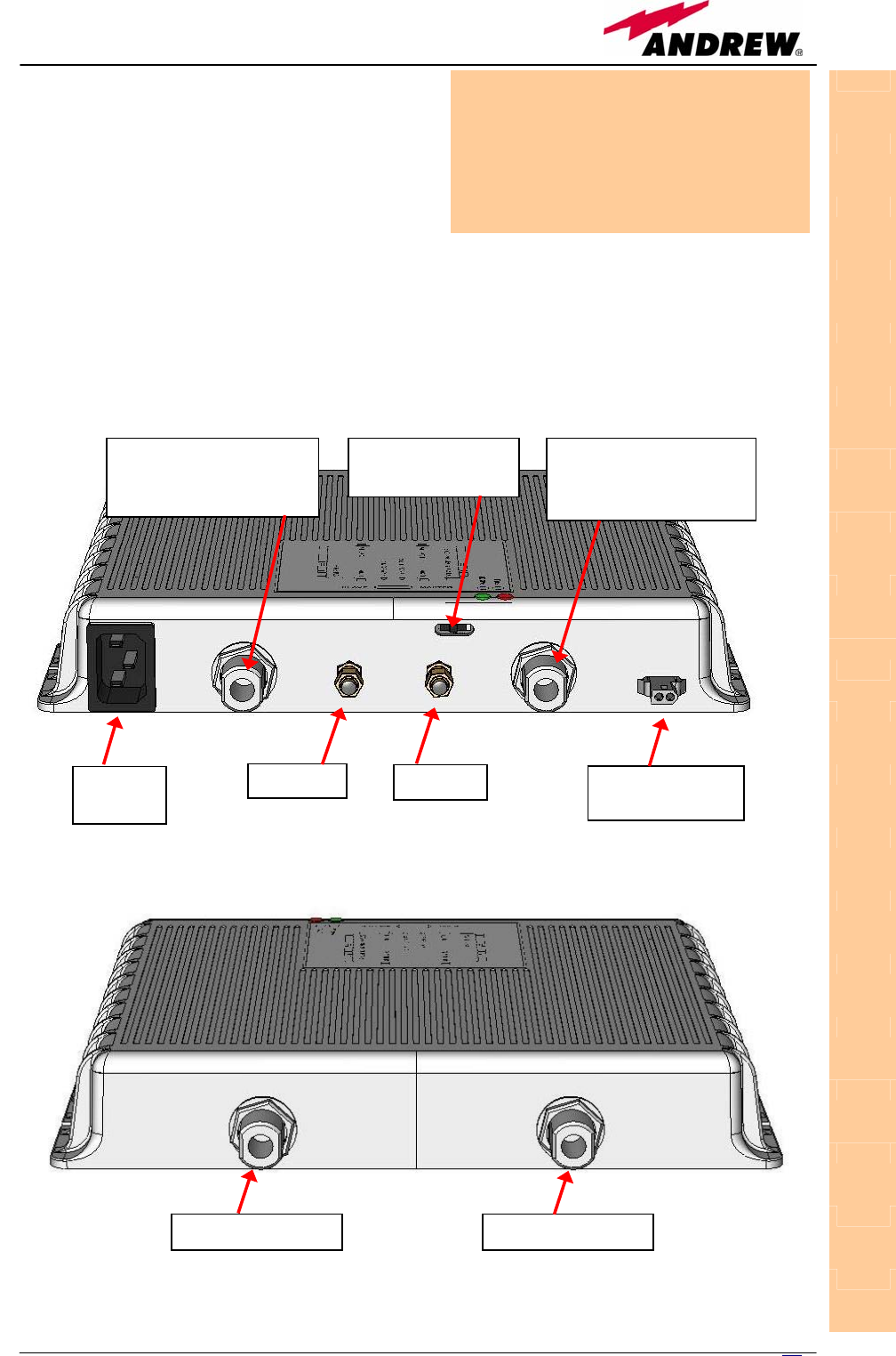
91
MN024-08
Description
Britecell Plus system allows to distribute
the WLAN services (802.11b and g)
through the auxiliary channels of the
remote units, while concentrating all the
Access Points together with the Master Unit.
The TFBW booster has to be connected to the remote unit auxiliary ports and
to a pair of WLAN dedicated antennas (one transmitting and the other one
receiving).
Moreover, an additional Wi-Fi booster (slave TFBW) can be cascaded to the
first one (master TFBW) so as to obtain a larger WLAN coverage.
RF ports
• 1 DL RF auxiliary input port for the signal from TFLN
• 1 DL RF auxiliary output port for the signal to a TFBW slave
• 1 TX antenna port
• 1 UL RF auxiliary input port for the signal from a TFBW slave
• 1 UL RF auxiliary output port for the signal to TFLN
• 1 RX antenna port
boosters.
TFBW
Module name:
Wi-Fi booster
TFBWx
MASTER/SLAVE
dip-switch
Power
supply
DL RF port (N-f),
connected to a TFAx
or to the master TFBW
UL RF port (N-f),
connected to a TFAx
or to the master TFBW
DL
A
UX UL AUX alarm output
port
RX antenna (N-f) RX antenna (N-f) TX antenna (N-f)
Fig. 3. 41 (a). TFBW booster: Front view
Fig. 3. 41 (b). TFBW booster: back view
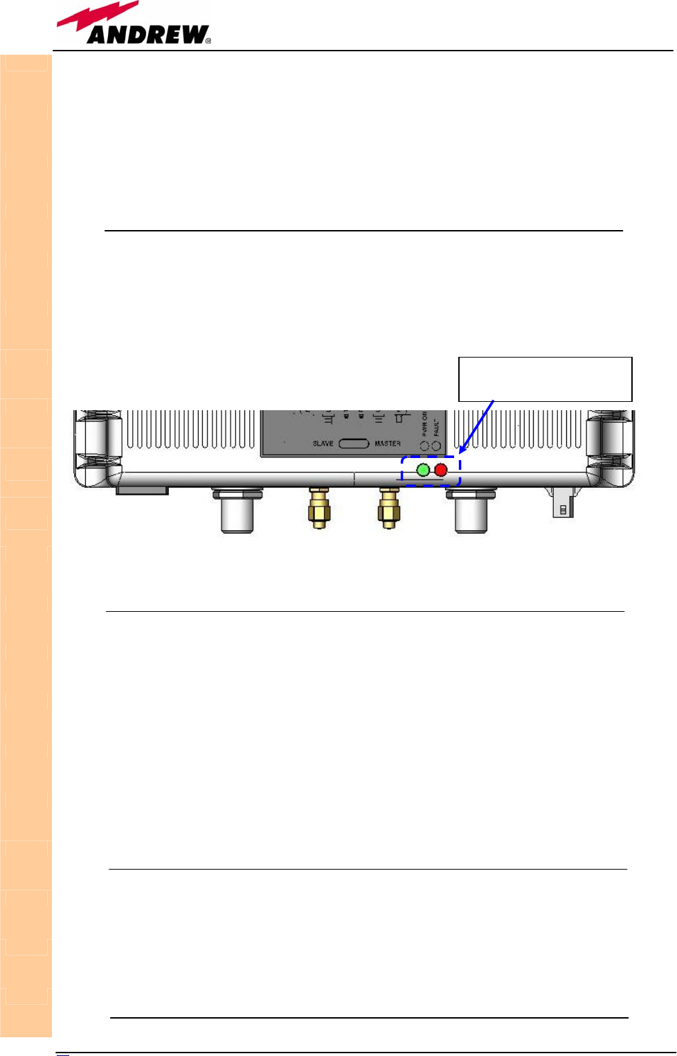
92 User Manual
Dimensions and weights
Dimensions: mm 38 x 240 x 200
(inches 1.5 x 9.4 x 7.9)
Weight: please refer to Bulletin PA-100596EN in order to know
the updated data about the TFBW weight.
Visual alarms:
Two control LEDs are provided on the TFBW front side (fig.3.42).
The green LED describes the power supply status, while the red LED describes
the major booster failures.
Dry contact alarms:
TFBW is provided with an alarm output port (fig. 3.41), which can be
connected to one of the dry-contacts ports available on TFAx remote units.
When a TFBW booster is been connected to the relevant TFAx remote unit
through dry-contact ports, any major alarm affecting the TFBW booster will
be conveyed to the remote unit itself, and signalled by the red LED both on
the TFBW warm side (fig. 3.42), and on the TFAx remote unit.
Moreover, the LMT software and the TSUN supervision interface (please refer
to TFBW troubleshhoting) will consider any TFBW major alarm as an external
alarm of the TFAx remote unit the TFBW booster is connected to.
Power supply:
TFBW WLAN booster is available both in a universal mains version (85 to 265
Vac powered: fig. 3.43a) and in a negative supply version (-72 to -36 Vdc
powered: fig. 3.43b). The power consumption of each TFWB module is 16W
max.
TFBW
GREEN LED: power on
RED LED: major alarm
Fig. 3.42: LED alarms on the TFBW warm side
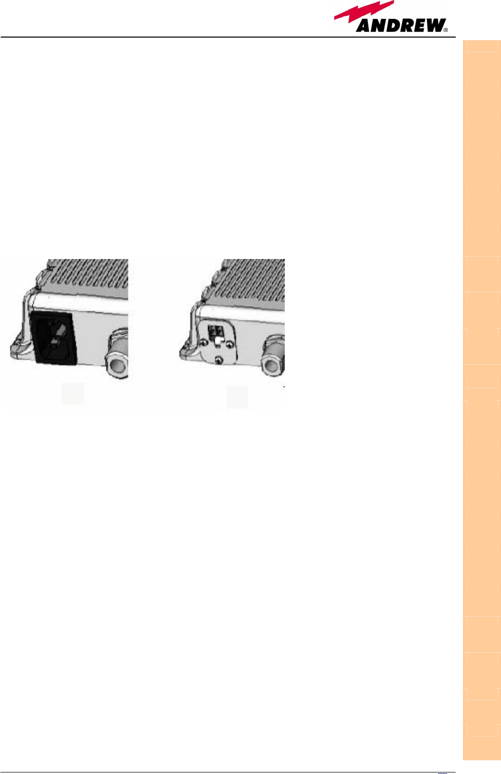
93
MN024-08
Warnings (to be read before the TFBW booster is
installed)
Choosing a proper installation site for the WLAN booster
• WLAN boosters are to be installed as close as possible to the radiating
antennas, in order to minimize coaxial cable length.
• When positioning the TFBW booster, consider that the position of the
related antennas should guarantee at least a 50dB isolation between the
antennas and the booster itself
• The TFBW booster is intended to be fixed on walls, false ceilings or other
flat vertical surfaces
TFBW installation and start-up
The TFBW booster can be fixed on walls, false ceilings or other flat vertical
surfaces, either directly or through a TKA01 installation kit (optional).
Installing a TFBW booster WITHOUT the TKA01 kit
The TFBW kit includes:
• 1 TFBW booster
• 2 50Ω SMA loads
• 2 RF jumpers (SMA-m; N-m), 1m-long
• 1 alarm cable, 1m-long
• mains plug or -48 Vdc plug (according to the chosen model).
To install the TFBW booster, please follow the next steps:
1. drill into the wall so as to install four M4 screw anchors (not included)
according to the dimensions indicated by the installation drawing in fig.
3.45a.
2. fix the TFBW booster to the wall by firmly screwing the anchors.
3. connect the RF cables according to what planned by the designer. Use a
specific torque wrench to fix each cable to the relevant ports.
TFBW
Fig. 3.43 : (a) IEC
connector on the rear
side of a 220Vac-
p
owered TFBW booster.
(b) 4-pole connector on
the rear side of a -48 Vdc
-
p
owered TFBW
(a) (b)
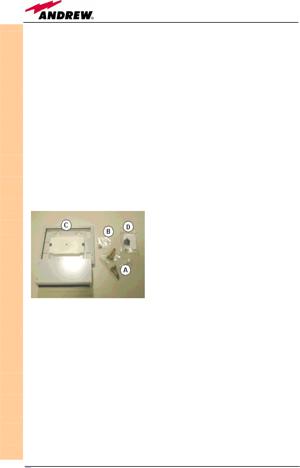
94 User Manual
4. connect the TFBW to the power supply. If the TFBW booster works
properly, both the green and the red LEDs should turn on for a while and
then switch off. If the LED red does not switches off, please contact the
manufacturer.
After installing the booster, please refer to the section TFBW booster start-up
in order to start-up the system properly.
Installing a TFBW booster WITH the TKA01 kit
The TFBW kit includes:
The TKA01 kit includes:
(please refer to fig. 3.44)
Once you have chosen the position where the TKA01 mounting case is going
to be mounted, please follow these instructions:
1. Unscrew the 4 screws which lock the lower cover of the TKA01 wall
bearing (see fig. 3.46a)
2. In order to install the M4 screw anchors (included) which shall hold up the
TKA01 wall bearing, drill into the wall according to the TKA layout shown
in fig. 3.45b.
3. Fix the TKA01 wall bearing by firmly screwing the anchors.
4. Fix the TFBW booster to the wall bearing by using the included screws
(fig. 3.46b).
5. Connect the RF cables coming from the transmitting and the receiving
antennas to the proper RF antenna ports (fig. 3.41b). Connect the UL and
DL RF ports (fig.3.41a, 3.46c). If the TFBW booster works as a master
unit and supports a slave one, connect also the DL and UL AUX ports.
6. Connect the alarm output port (fig. 3.41a) if you want the major alarms
on the TFBW booster could be checked through the relevant remote unit
TFBW
Fig. 3.44: The TKA01 installation kit
1. a TFBW booster
2. a 50 Ω load
3. a VDE connector or a -48 Vdc plug (according
to the chosen model)
A. 4 screw anchors (fixing the wall
bearing to the wall)
B. 5 screw anchors (fixing the TFAx
case A to the wall mounting box “C”)
C. A wall mounting boc
D. a splice holder (pleased note that
this standard TKA01 accessory is not
used for mounting the TFBW
booster, since it has no optical

95
MN024-08
and controlled through the LMT software or through the TSUN supervision
interface.
7. If the booster -48 Vdc powered (fig., use the -48 Vdc plug (included) in
order to connect the unit to the -48 Vdc mains. If the booster is 85/264
Vac-powered, fix the 85/264 Vac plug (included) on to a power cord (not
included), and use this cable in order to connect the unit to the mains. If
the TFBW booster works properly, both the green and the red LEDs should
turn on for a while and then switch off. If the LED red does not switches
off, please contact the manufacturer.
Fix the lower cover by fastening the 4 screws (fig.3.12f).
TFBW booster troubleshooting
The red LED on the TFBW warm side (fig. 3.45) reveals a power amplifier bias
fault. If such a fault occurs, the alert notification is signalled also by the
switching on of the red LED on the relevant TFAx remote unit, provided that
the TFBW alarm output port has been properly connected to the TFAx external
alarm connector (fig. 3.46).
If controlled through the LMT software or through the TSUN supervision
interface, the TFBW power amplifier fault appears as an external alarm of the
TFAx remote unit to which its alarm output port is connected. Please refer to
the LMT or to the TSUN supervision manual for further details.
When the TFBW power amplifier fault is signalled by the red LED on the TFBW
booster and on its relevant remote unit, or by the LMT software or the TSUN
interface, please contact the manufacturer.
TFBW
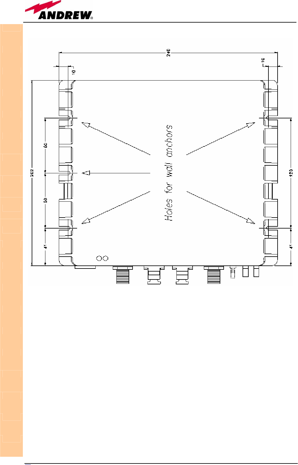
96 User Manual
TFBW
Fig. 3.45 (a): Layout of the TFBW booster, with wall anchor quotes
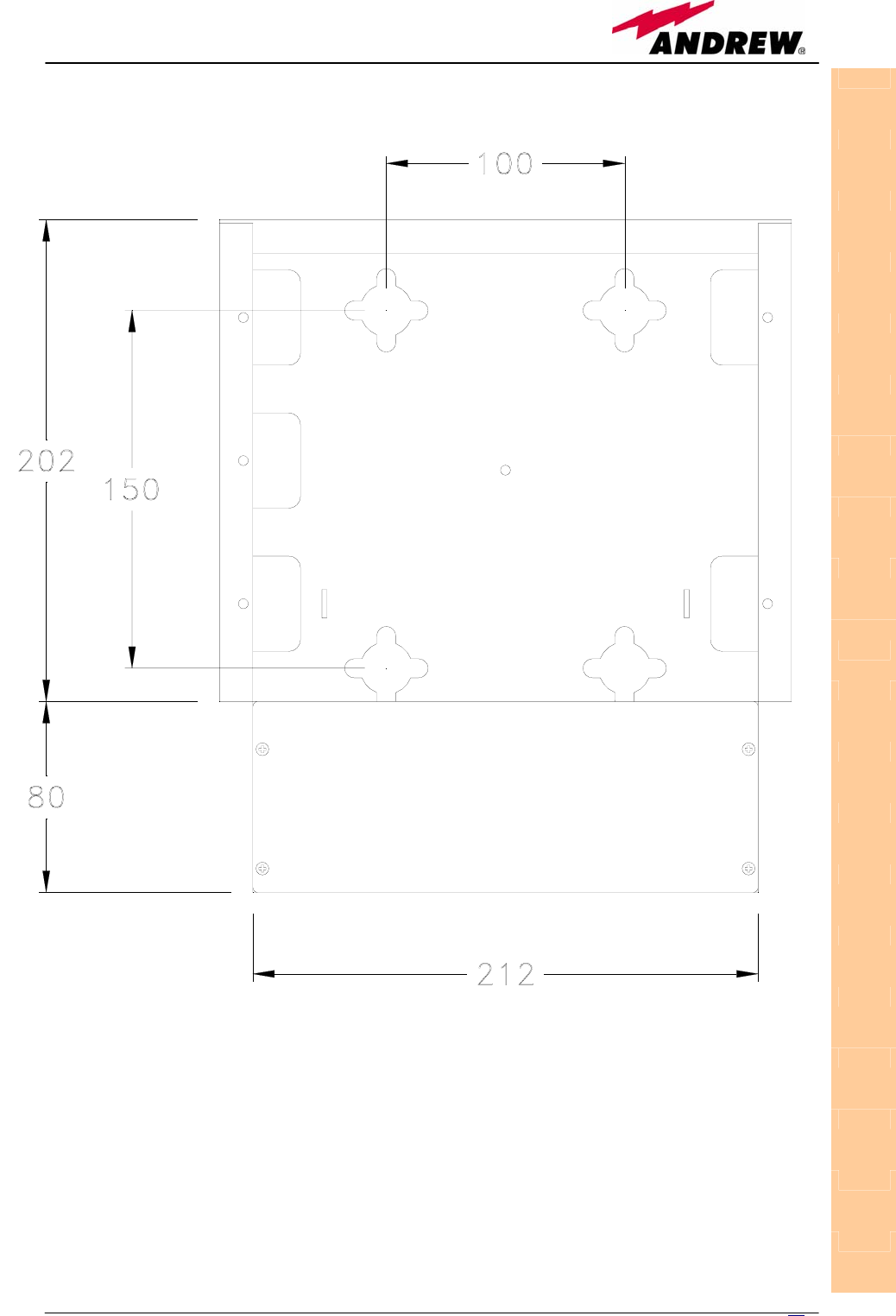
97
MN024-08
TFBW
Fig. 3.45 (b): Layout of the TKA01 wall bearing, with wall anchor quotes
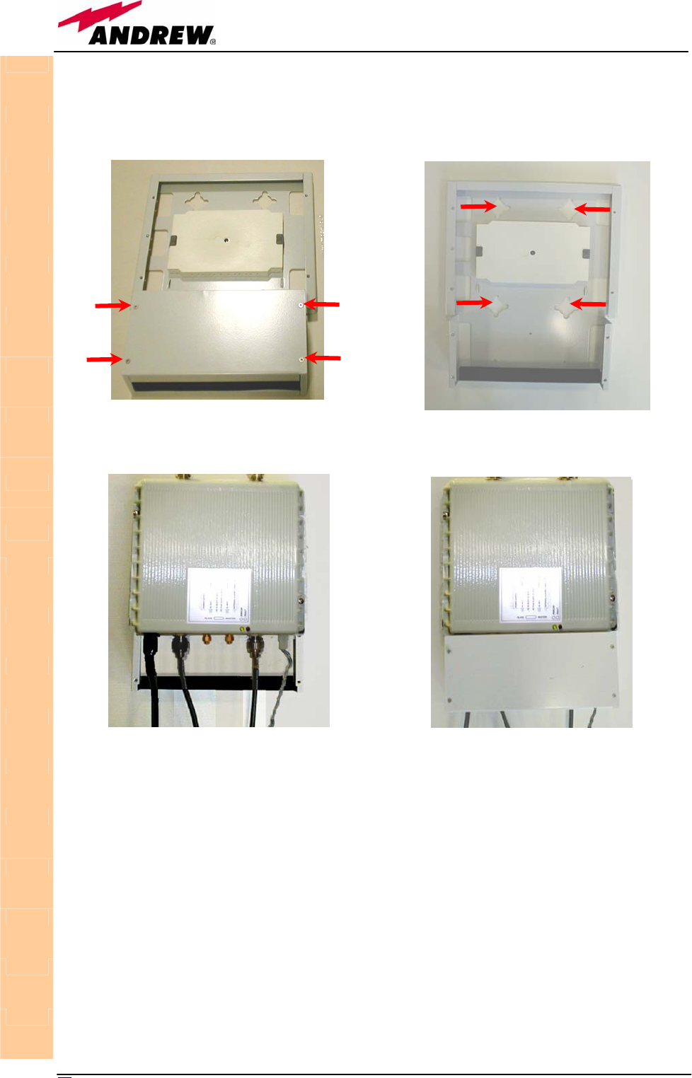
98 User Manual
TFBW
(a) (b)
Fig. 3.46: Mounting the TFBW booster with a TKA01 installation kit.
(d)
(c)

99
MN024-08

100 User Manual
4. Fast Master Unit
TFLF
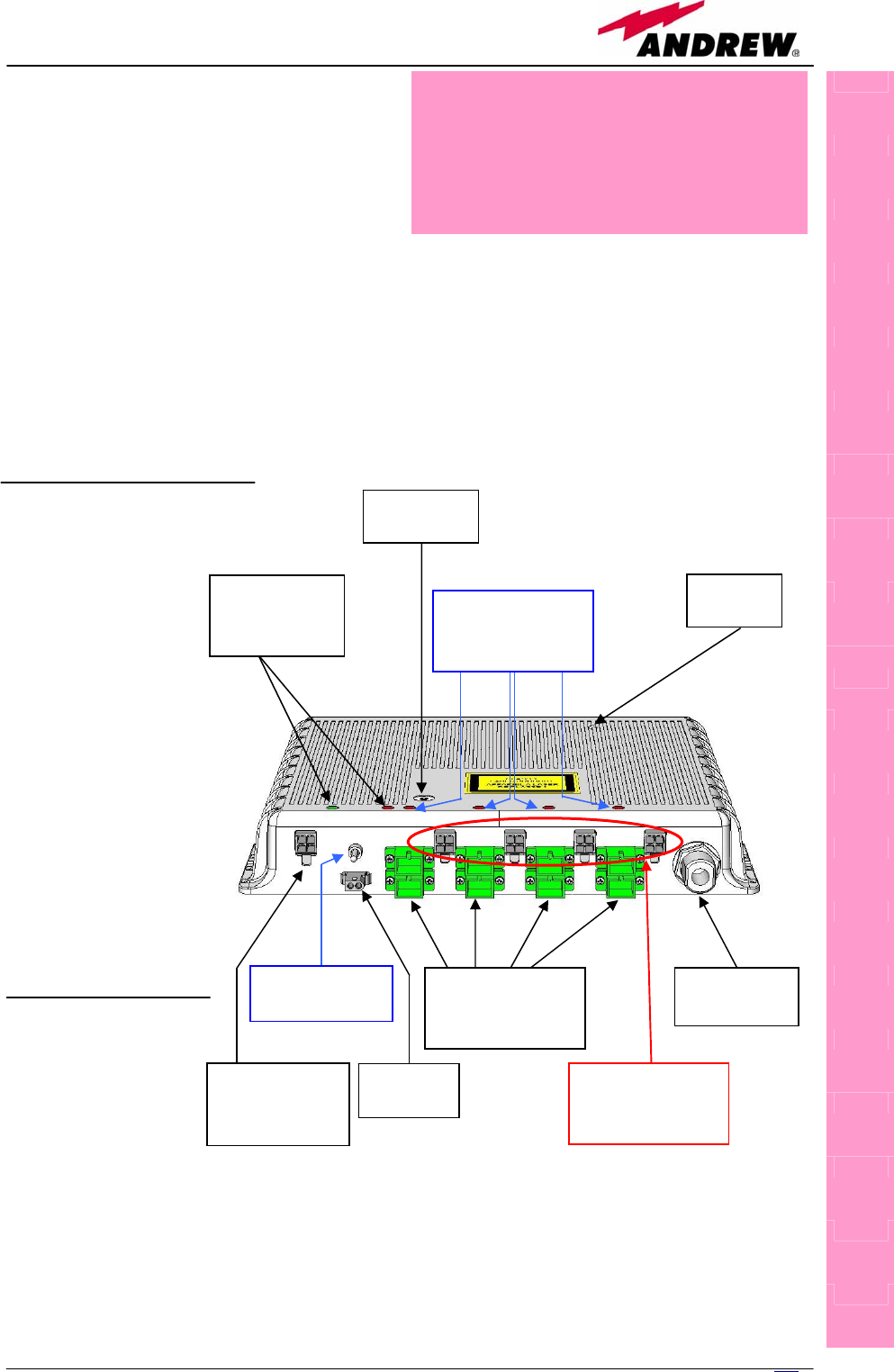
101
MN024-08
Main tasks carried out by
the TFLF module
Downlink (DL):
¾ Power level adjustment (ALC)
¾ RF-to-optical conversion of the input RF signal
¾ Optical splitting: input RF signal is split onto 4 optical outputs
Uplink (UL):
¾ Uplink Gain adjustment (0 to 20dB, 5dB step)
¾ Optical-to-RF conversion of the 4 input optical signals
¾ Automatic Gain Control (AGC) of each converted signal to compensate
optical losses
¾ RF combining of the 4 adjusted signals into a single RF path then they
are filtered and duplexed into the RF port.
RF ports:
¾ 1 Duplexed
DL/UL RF port
Note:
The maximum input
levels at RF ports is
+27dBm (please
refer to datasheet
for further
information), as
well as the UL path
may require a
power adjustment
to fill within the
BTS receiving range
(use the built-in
adjustable
attenuator).
Optical ports
¾ 4 DL optical
output ports
(SC/APC)
¾ 4 UL optical input
ports (SC/APC)
TFLF
Power Supply
Switch
Power Supply
Connector
(-48Vdc)
Alarm
Contacts
Optical UL and
DL Connectors
to Remote Units
DL/UL RF
Port to BTS
Remote Unit
Power Supply
Connectors
Master Unit
alarm and
status LEDs
UL Step
A
ttenuator
Store
Button
Remote Units
alarm and link
status LEDs
Fig. 4.1 Fast Remote Unit
Module name:
Fast remote unit
TFLF
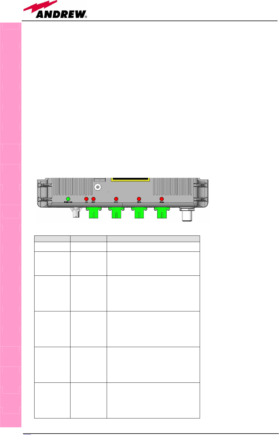
102 User Manual
Dimensions and Weight
Dimensions: mm 240 x 200 x 36
(inches 9.5 x 7.9 x 1.4)
Weight: please refer to Britecell Plus Bulletin PA-100595EN in
order to know the updated data about the TFBW
weight
TFLF visual alarms
The TFLF is provided with 6 LEDs (see on the right) showing status and alarm
information.
LEDs meaning is reported on the rightward table.
Note: In case the four TFLF optical ports are not all connected to Remote Units, the
unused ports must be properly masked, through the STORE button, at commissioning
to avoid spurious alarms
TFLF
Label LED colour Meaning
PWR ON Green Power Supply status OK
LU Red
General TFLF failure, it can be:
- DL optical power fail
- UL or DL amplifier failure
- Temperature alarm
RU1 Red
From Remote Unit 1 it monitors:
- UL or DL AGC out of range (flashing)
- UL or DL optical power fail
- DL amplifier failure
- External alarm 1
- External alarm 2
RU2 Red
From Remote Unit 2 it monitors:
- UL or DL AGC out of range (flashing)
- UL or DL optical power fail
- DL amplifier failure
- External alarm 1
External alarm 2
RU3 Red
From Remote Unit 3 it monitors:
- UL or DL AGC out of range (flashing)
- UL or DL optical power fail
- DL amplifier failure
- External alarm 1
External alarm 2
RU4 Red
From Remote Unit 4 it monitors:
- UL or DL AGC out of range (flashing)
- UL or DL optical power fail
- DL amplifier failure
- External alarm 1
External alarm 2
Fig. 4.2 The 6 LEDs
on the warm side of
the Fast Remote Unit
Table 4.1:
Summary of TFLF
LED meaning
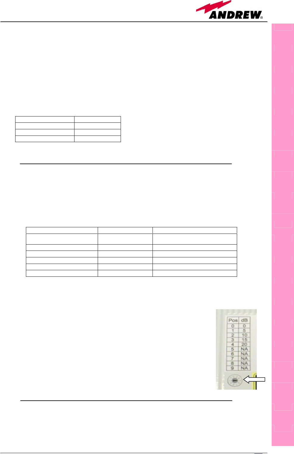
103
MN024-08
Dry contact alarms:
TFLF is also provided with dry contacts outputs (connectable through .062”
MOLEX plugs) to report alarm condition to third party equipment (i.e. BTS or
repeater).
The dry contact status is reported in the table rightwards.
Note: in case of power supply failure the system is not powered and the dry
contacts will be automatically driven to a “closed” condition.
UL Attenuation Adjustment:
The TFLF is designed to be compatible with most pico/micro BTSs. It is also
provided with an internal adjustable attenuator for the UL path allowing 20dB
attenuation range, 5dB step. Suggested settings are reported in the table 4.3.
To adjust the value a flat screwdriver can be used as per the
picture 4.2.
TFLF power supply
Each TFLF Fast Master Unit requires -48Vdc power supply.
Alarm Condition Contact Position
None Open
Minor Open
Major Closed
TFLF
Composite Input Power External Attenuator UL Adjustable Attenuator Setting
+37dBm 20dB (5W average) 0dB (Position nr. 0)
+33dBm 20dB (2W average) 0dB (Position nr. 0)
+24dBm 10dB 10dB (Position nr. 2)
+20dBm 5dB 15dB (Position nr. 3)
+14dBm 0dB 20dB (Position nr. 4)
+13dBm 0dB 20dB (Position nr. 4)
Tab. 4.2: TFLF dry-contact meaning
Fig. 4.3: Uplink Attenuator
Tab. 4.3: TFLF UL attenuation suggested values

104 User Manual
The power consumption of each TFLF is 10W.
An optional external adapter 220Vac to -48Vdc is available.
The TFLF also provide connections for the distribution of the -48Vdc to the
Remote Units by means of composite cable. Each supply port is protected
against overloads, short and surge with a self recovery fuse and surge
protection. The power switch will disconnect the remote unit power supply in
case of overcurrent.
The power consumption of each TFLF with 4 Remote Units is lower than 80W.
Warnings (to be read before the TFLF installation)
Dealing with optical output ports
• The TFLF Fast Master Unit contains semiconductor lasers. Invisible laser
beams may be emitted from the optical output ports. Do not look towards
the optical ports while equipment is switched on.
Handling optical connections
• When inserting an optical connector, take care to handle it so smoothly
that the optical fibre is not damaged. Optical fibres have to be single-mode
(SM) 9.5/125µm.
• Typically, Britecell Plus equipment is provided with SC-APC optical
connectors. Inserting any other connector will result in severe damages.
• Do not force or stretch the fibre pigtail with radius of curvature less than 5
cm.
• Remove adapter caps only just before making connections. Do not leave
SC-APC adapters open, as they attract dust. Unused SC-APC adapters
must always be covered with their caps.
• Do not touch the adapter tip. Clean it with a proper tissue before inserting
each connector into the sleeve. In case adapter tips need to be better
cleaned, use pure ethyl alcohol
TFLF cautions
• The TFLF modules must be handled with care in order to avoid damage to
electrostatic sensitive devices.
• Take care to meet expected requirements on RF ports. An external fixed
attenuator could be necessary when the power coming from the BTS
exceeds the required levels to avoid damages in circuitry or increase of
spurious emissions.
TFLF
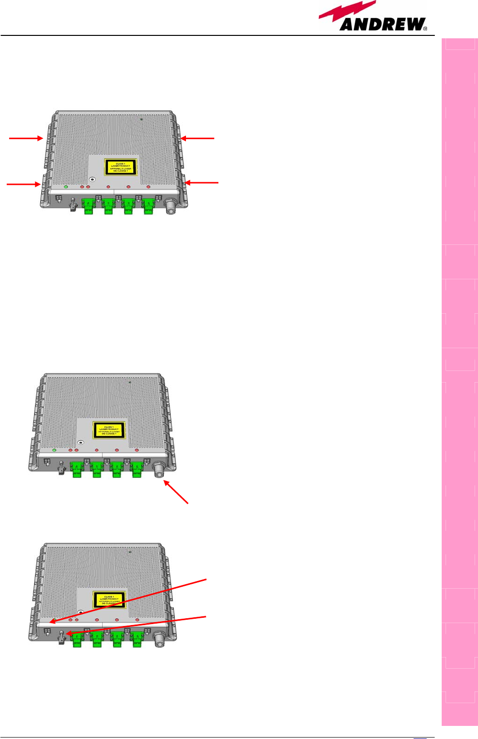
105
MN024-08
TFLF installation
First of all fix the Fast Master Unit to
the wall by means of four screws (see
fig. 4.5 for wall anchor quotes).
Vertical position is suggested for ease
thermal dissipation.
Verify that the composite cable has been laid and already properly
connectorised. Two preconnectorised fibre optic cables and a power supply
cable with 4-pole connector should be ready for connection to each Remote
Unit and to each port of the TFLF.
Remove the caps from the optical connectors and connect the connectorised
fibre optic cables to the optical ports of the unit. Then connect the previously
connectorised copper cable to the proper power plug for each Remote Unit.
Verify the output power of the BTS or
repeater which is going to be connected
and check if external attenuation is
required then set the UL attenuation
through a flat screw driver (refer to the
table reported in the relevant section)
Apply the ferrite to the power supply
cable.
Connect the provided patchcord to the -
48Vdc power supply and insert the
connector into the TFLF power plug.
Then switch one the unit by means of
the ON/OFF power switch.
Note: if 220Vac power supply is
available on site, use the suitable
optional adapter.
As you switch on the system, carefully refer to the TFLF Start-Up section.
TFLF
Fig. 4.4
Fig. 4.4
Fig. 4.4

106 User Manual
TFLF start-up
Before the TFLF Master Unit is switched on, make sure that:
• every Remote Unit has been connected to relevant port of the Master Unit
• each remote unit has been connected to its coverage antennas
After that, remember that only when all the remote units are already on, the
Master Unit itself can be turned on.
Once the Master Unit has been switched on, the following steps have to be
followed:
1. Wait until the communication between TFLF and Remote Units is
established and alarms related to unused ports arise.
2. Verify that all used ports don’t have any active alarm. In case an
alarm is present follow the troubleshooting procedure.
3. Press the STORE button for at least 5sec. (all TFLF LEDs will flash for
3sec.) in order to mask unused ports.
Removing the TFLF
Switch off the Master Unit power supply and remove the power cable.
Remove the SC-APC optical connectors and insert the protection caps into
TFLF optical ports. Then:
• unscrew the 4 screws and remove the unit
• put the removed TFLF unit in its safety box
TFLF troubleshooting
In case a TFLF Fast Master Unit has any problem, this will be easily revealed
through LEDs which reveals not only failures of the TFLF itself but also
malfunctions located on related remote units.
ALARM
CODE
(TSUN
description)
ALARM
DESCRIPTION ACTIVE LED
SUPERVISI
ON
PRIORITY
LEVEL
ACTION
RECOMMENDED
RELÉ
PRIORITY
LEVEL
(subrack)
DL optical
power fail
TFLF DL optical power
from the laser is too
low LU MAJOR Return the unit CLOSED
DL RF alarm DL RF amplifier LU MAJOR Return the unit CLOSED
UL RF alarm UL RF amplifier LU MAJOR Return the unit CLOSED
Temperature
alarm Over-temperature
alarm LU (flashing) MINOR Check ventilation
and environment OPEN
Power supply
alarm Power supply fault LU
(PWR ON off) MAJOR Return the unit CLOSED
UL1 optical
power fail TFLF UL1 optical
power is too low
RU1 MAJOR Check for fibre or
splice stresses and CLOSED
TFLF

10
7
MN024-08
UL2 optical
power fail UL2 optical power is
too low RU2 MAJOR CLOSED
UL3 optical
power fail UL3 optical power is
too low RU3 MAJOR CLOSED
UL4 optical
power fail UL4 optical power is
too low RU4 MAJOR
clean the optical
connectors. If the
alarm still persists it
reveals a laser fault
so return the unit CLOSED
DL1 optical
power fail DL1 optical power is
too low RU1 MAJOR CLOSED
DL2 optical
power fail DL2 optical power is
too low RU2 MAJOR CLOSED
DL3 optical
power fail DL3 optical power is
too low RU3 MAJOR CLOSED
DL4 optical
power fail DL4 optical power is
too low RU4 MAJOR
Check for fibre or
splice stresses and
clean the optical
connectors. If alarm
still persists it
reveals a laser fault
so return the unit CLOSED
UL1 AGC out
of range
The optical power
received on UL1 is too
low and can’t no more
be compensated
RU1 MINOR
(flashing) OPEN
UL2 AGC out
of range
The optical power
received on UL2 is too
low and can’t no more
be compensated
RU2 MINOR
(flashing) OPEN
UL3 AGC out
of range
The optical power
received on UL3 is too
low and can’t no more
be compensated
RU3 MINOR
(flashing) OPEN
UL4 AGC out
of range
The optical power
received on UL4 is too
low and can’t no more
be compensated
RU4 MINOR
(flashing)
Check for fibre or
splice stresses and
clean the optical
connectors. If alarm
still persists it
reveals a laser fault
so return the unit
OPEN
DL1 AGC out
of range
The optical power
received on UL1 is too
low and can’t no more
be compensated
RU1 MINOR
(flashing) OPEN
DL2 AGC out
of range
The optical power
received on UL2 is too
low and can’t no more
be compensated
RU2 MINOR
(flashing) OPEN
DL3 AGC out
of range
The optical power
received on UL3 is too
low and can’t no more
be compensated
RU3 MINOR
(flashing) OPEN
DL4 AGC out
of range
The optical power
received on UL4 is too
low and can’t no more
be compensated
RU4 MINOR
(flashing)
Check for fibre or
splice stresses and
clean the optical
connectors. If alarm
still persists it
reveals a laser fault
so return the unit
OPEN
DL1 RF alarm DL1 RF amplifier RU1 MAJOR Return the unit CLOSED
DL2 RF alarm DL2 RF amplifier RU2 MAJOR Return the unit CLOSED
DL3 RF alarm DL3 RF amplifier RU3 MAJOR Return the unit CLOSED
DL4 RF alarm DL4 RF amplifier RU4 MAJOR Return the unit CLOSED
RU1 External 1
alarm External 1 alarm from
RU1 RU1 MAJOR
Check the external
device connected to
external 1 and the
RU1 dry-contact
functionality
CLOSED
RU2 External 1
alarm External 1 alarm from
RU2 RU2 MAJOR
Check the external
device connected to
external 1 and the
RU2 dry-contact
functionality
CLOSED
RU3 External 1
alarm External 1 alarm from
RU3 RU3 MAJOR
Check the external
device connected to
external 1 and the
RU3 dry-contact
functionality
CLOSED
RU4 External 1
alarm External 1 alarm from
RU41 RU4 MAJOR
Check the external
device connected to
external 1 and the CLOSED

108 User Manual
RU4 dry-contact
functionality
RU1 External 2
alarm External 2 alarm from
RU1 RU1 MAJOR
Check the external
device connected to
external 2 and the
RU1 dry-contact
functionality
CLOSED
RU2 External 2
alarm External 21 alarm from
RU2 RU2 MAJOR
Check the external
device connected to
external 2 and the
RU2 dry-contact
functionality
CLOSED
RU3 External 2
alarm External 2 alarm from
RU3 RU3 MAJOR
Check the external
device connected to
external 2 and the
RU3 dry-contact
functionality
CLOSED
RU4 External 2
alarm External 2 alarm from
RU41 RU4 MAJOR
Check the external
device connected to
external 2 and the
RU4 dry-contact
functionality
CLOSED
The previous table reports a brief description of the TFLF alarms, together with a
reference to the corresponding alerted LEDs.
As the table shows, all major alarms are signalled also closing the dry contacts available
on the TFLF allowing sending this information to any external equipment (i.e. BTS or
repeater)
One of the LEDs RU1, 2, 3, 4 might turn on not only to indicate a high optical loss
detected by the TFLF, but also to reveal a remote unit failure. Understanding the reason
why one of this LEDs is on (a remote unit failure, an optical cable fault or an external
equipment malfunction) can be done following the troubleshooting procedure reported
hereinafter.
Quick troubleshooting procedure
(The following troubleshooting procedure is summarised by the flow-chart in
fig. 4.7a)
1. In case the TFLF general alarm (LED LU) is on replace the faulty TFLF
master unit with a new one and contact the manufacturer for assistance.
2. In case one of the LEDs RU1, 2, 3 or 4 is on, the corresponding TFLF
adapter might be dirty. Try cleaning it using pure ethyl alcohol. If the
LED is still on go to the corresponding remote unit side and check the
red LED upon the warm side:
a. If it is off, the optical cables or the optical connections are
supposed to have some problem on UL path. Refer to fibre optic
UL troubleshooting for more information (fig. 4.7b).
b. If it is on, refer to remote unit troubleshooting presented in the
previous remote unit section
Fiber optic UL troubleshooting
(The following procedure is summarized by the flow-chart in fig. 4.7b)
1. Check if there is any point where the fibre experiences a small radius of
curvature. In this case, rearrange the optical path in order to avoid
sharp bends (if necessary, replace the optical cable with a longer one). If
this makes the TFLF LED switch off, troubleshooting has been successful.
Otherwise, follow next steps.
TFLF
Tab. 4.4: TFLF alarm descri
p
tion

109
MN024-08
2. Check if the SC-APC connectors are properly installed at both fibre ends
(i.e. TFLF and TFAx ports). If not fix better SC-SPC connectors to relevant
adapters. If this makes the TFLF LED switch off, troubleshooting has been
successful. Otherwise, follow next steps.
3. Disconnect the optical fibre and clean it at both fibre ends (i.e. TFLF side
and TFAx side) then reconnect the fibre to relevant ports. In case this
makes the TFLF LED switch off, troubleshooting has been successful.
Otherwise, follow next steps.
4. Disconnect the optical SC-APC connector from TFLF UL port, and measure
the output power POUT(UL) at corresponding fibre end. Then, go to the
TFAx side, disconnect the optical SC-APC connector from TFAx UL port
and measure the input power PIN(UL) coming out of the TFAx UL port.
5. Calculate the UL fibre attenuation AUL as: AUL [dB] = PIN(UL) – POUT(UL)
a. If AUL > 4dB, the fibre optic cable has some problems or cable
path is too long. Replace it.
b. If AUL < 4dB, then TFAx remote unit should be faulty. Before
replacing it, contact for assistance
TFLF
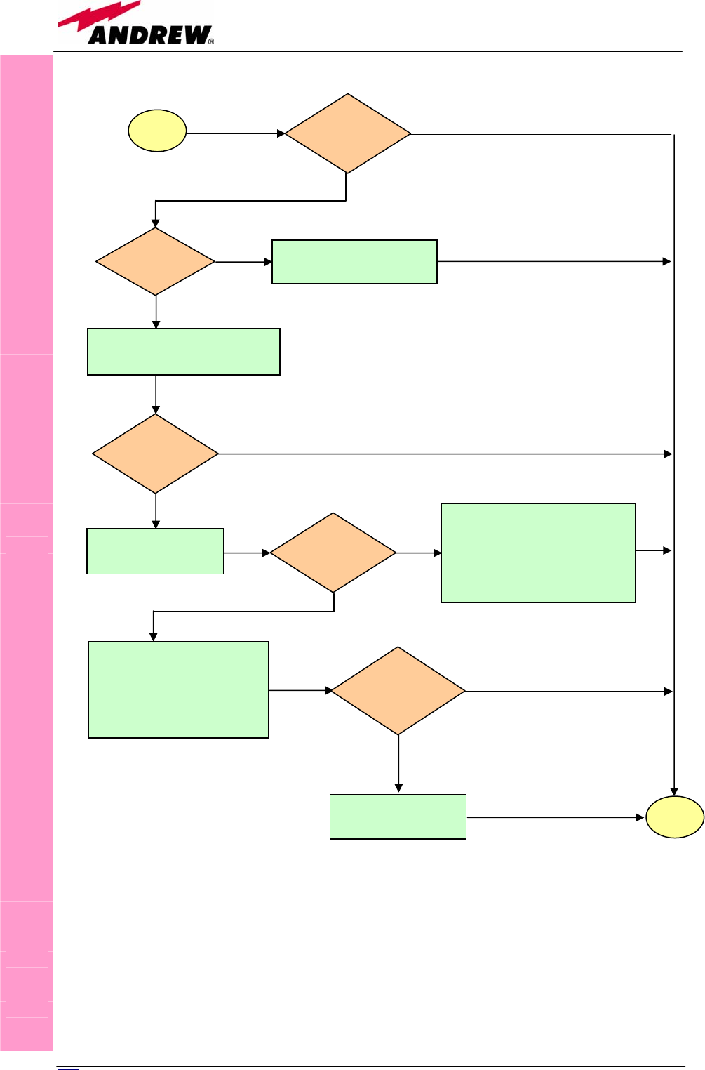
110 User Manual
TFLF
Fig. 4.7 (a): Flow-chart describing the quick troubleshooting procedure
start
Which red
LED is ON?
RU1, 2, 3 or 4
Replace the faulty TFLF
Clean corresponding SC-APC
optical adapter and connector
Yes
Is any red LED
ON upon the
TFLF?
N
o
No
Go to corresponding
remote unit side
Verify if any external
equipment or dry contact
p
ort has some problems
Refer to the remote unit
dry-contact troubleshooting
No
Yes
Yes
UL optical cables or optical
connections are supposed to
have some problems. Refer to
fibre optic UL troubleshooting
(fig. 4.7b)
No
Refer to remote unit
troubleshooting
Yes
end
Is red LED
upon TFLF
still ON?
Is red LED
upon remote
unit ON?
Is red LED
upon remote
unit still ON?
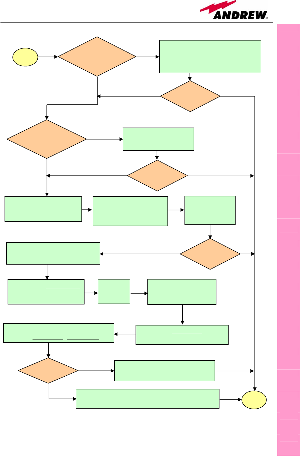
111
MN024-08
TFLF
Fig. 4.7 (b): Flow-chart describing the fibre optic UL troubleshooting
start
Is there any small
radius of curvature
of the fibre?
Rearrange the optical path in order to
avoid sharp bends. If necessary
replace the optical cable with a
lon
g
er one.
Is the red LED
upon TFLF still
ON?
Are SC-APC
connectors properly
installed at both fibre
ends?
Fix SC-APC connectors
properly to adapters.
Yes
N
o
N
o
Y
es
No
Y
es
N
o
Y
es
Disconnect the optical SC-APC
connector from TFLN UL port.
Clean the optical SC-APC
p
orts both on TFLN and
TFAx side.
Disconnect the optical fibre
and clean it at both ends.
Re-connect the
fibre to relevant
p
orts.
Measure the output power
at the corresponding fibre
end
Measure the input power entering
the fibre.
Go to the
TFAx
side
Disconnect the optical
SC-APC connector
from TFAx UL
p
ort.
Calculate the UL fibre attenuation:
AUL[dB]=input power - output power
Is AUL > 4dB? Fibre optic cable has some problems.
Replace it.
The TFAx remote unit should be faulty. Before
replacing it, contact for assistance. end
No
Y
es
No
Y
es
Is the red LED
upon TFLF still
ON?
Is the red LED
upon TFLF still
ON?

112 User Manual