Andrew Wireless Innovations Group TFAM1719 Optical wireless distribution system User Manual Manual 2
Andrew Wireless Innovations Group Optical wireless distribution system Manual 2
UserManual.wiki
>
Andrew Wireless Innovations Group
>
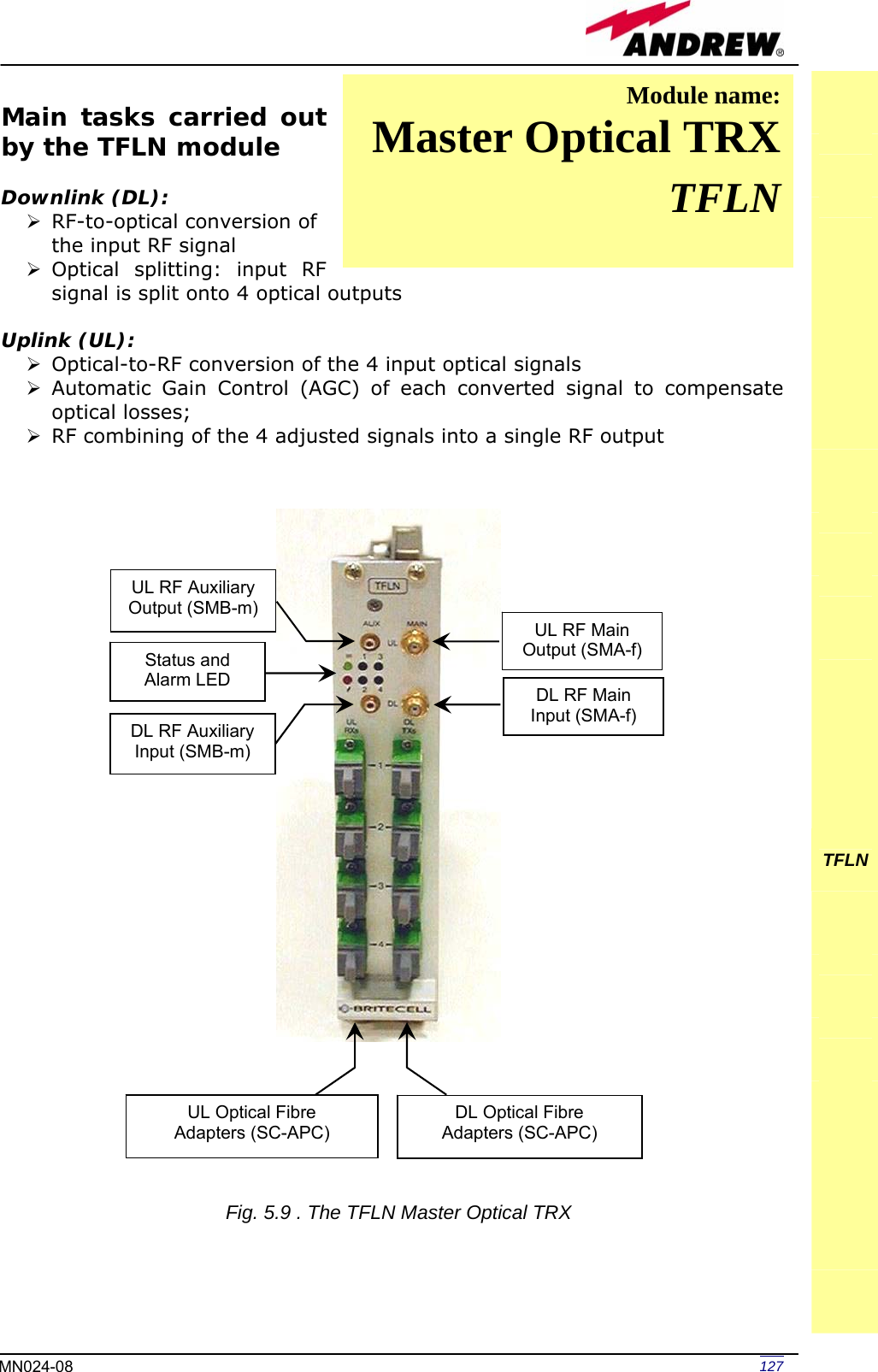
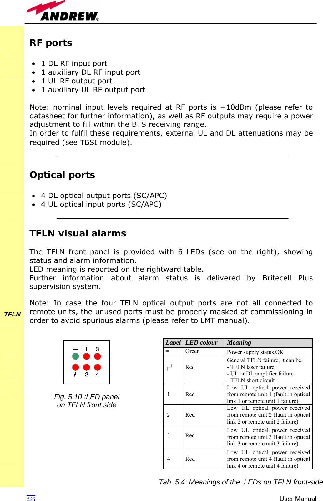
TFAM1719 User Manual
>
Manual 2
Contents
1.
Manual
2.
Manual 2
Manual 2
Navigation menu
Upload a User Manual
Namespaces
Wiki Guide
HTML
PDF
Info
Views
User Manual
Discussion / Help
Navigation
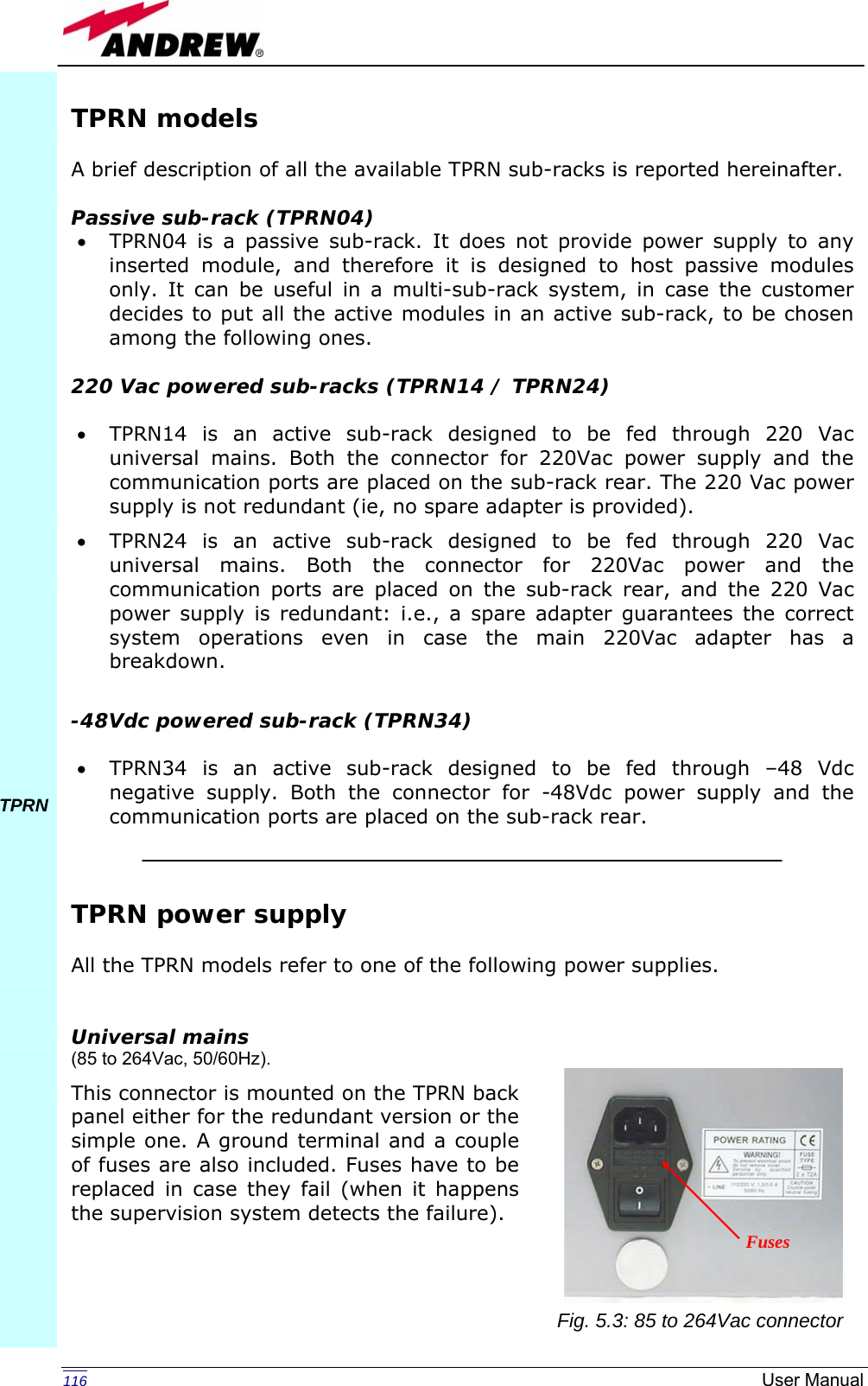
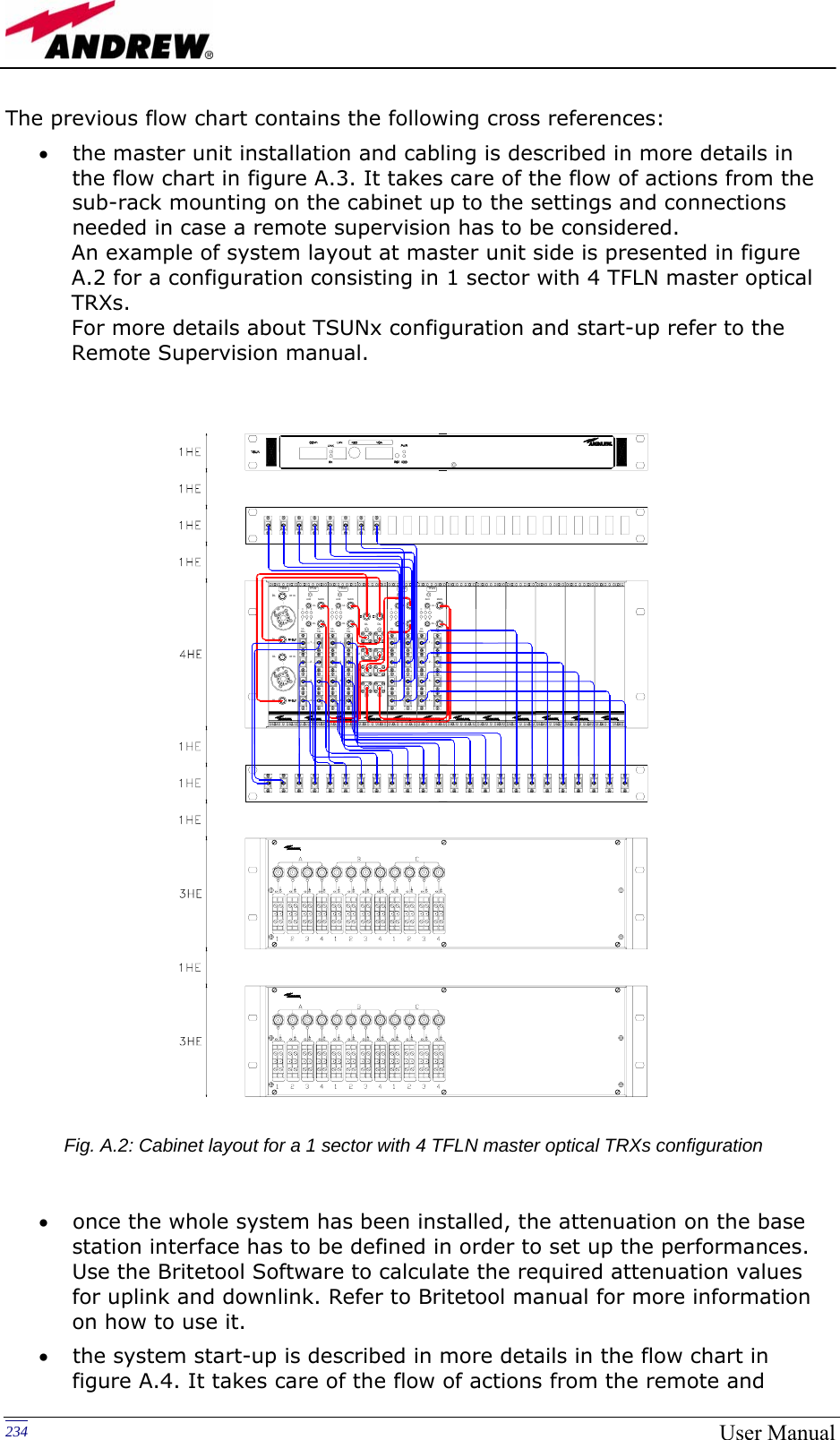
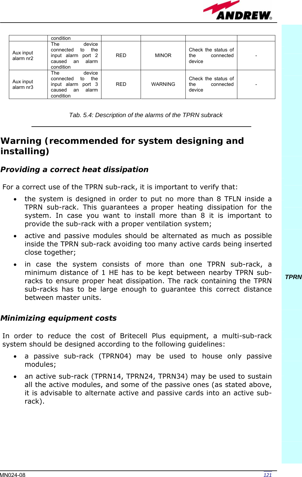
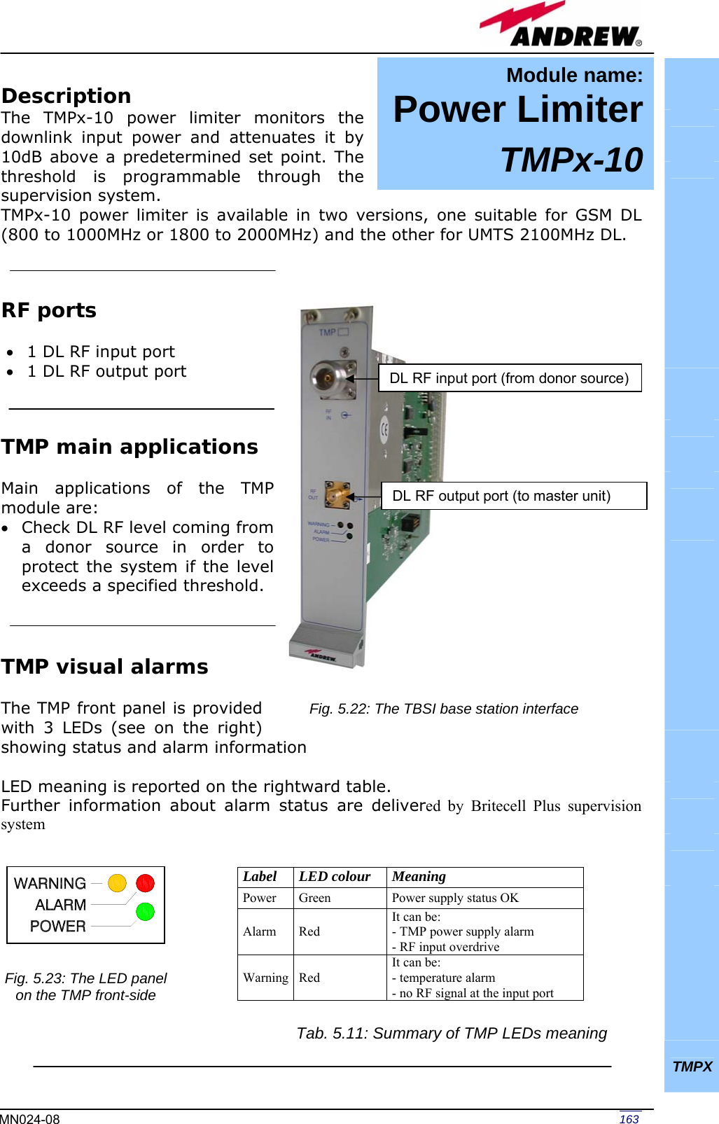
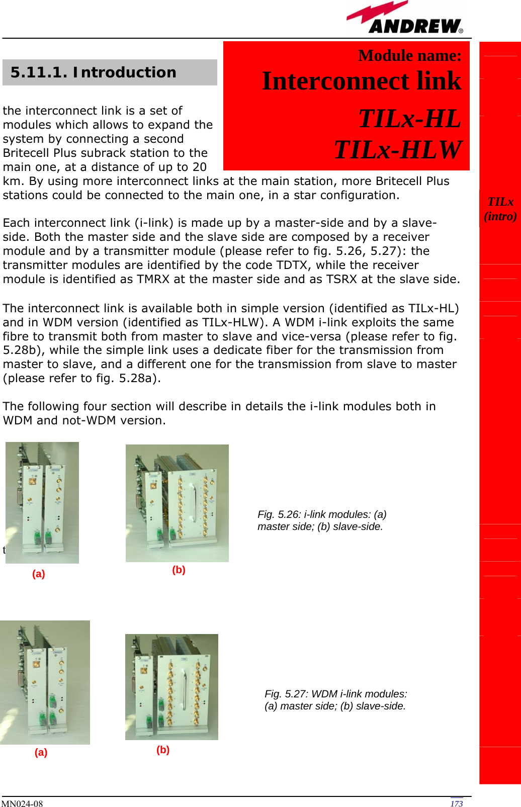
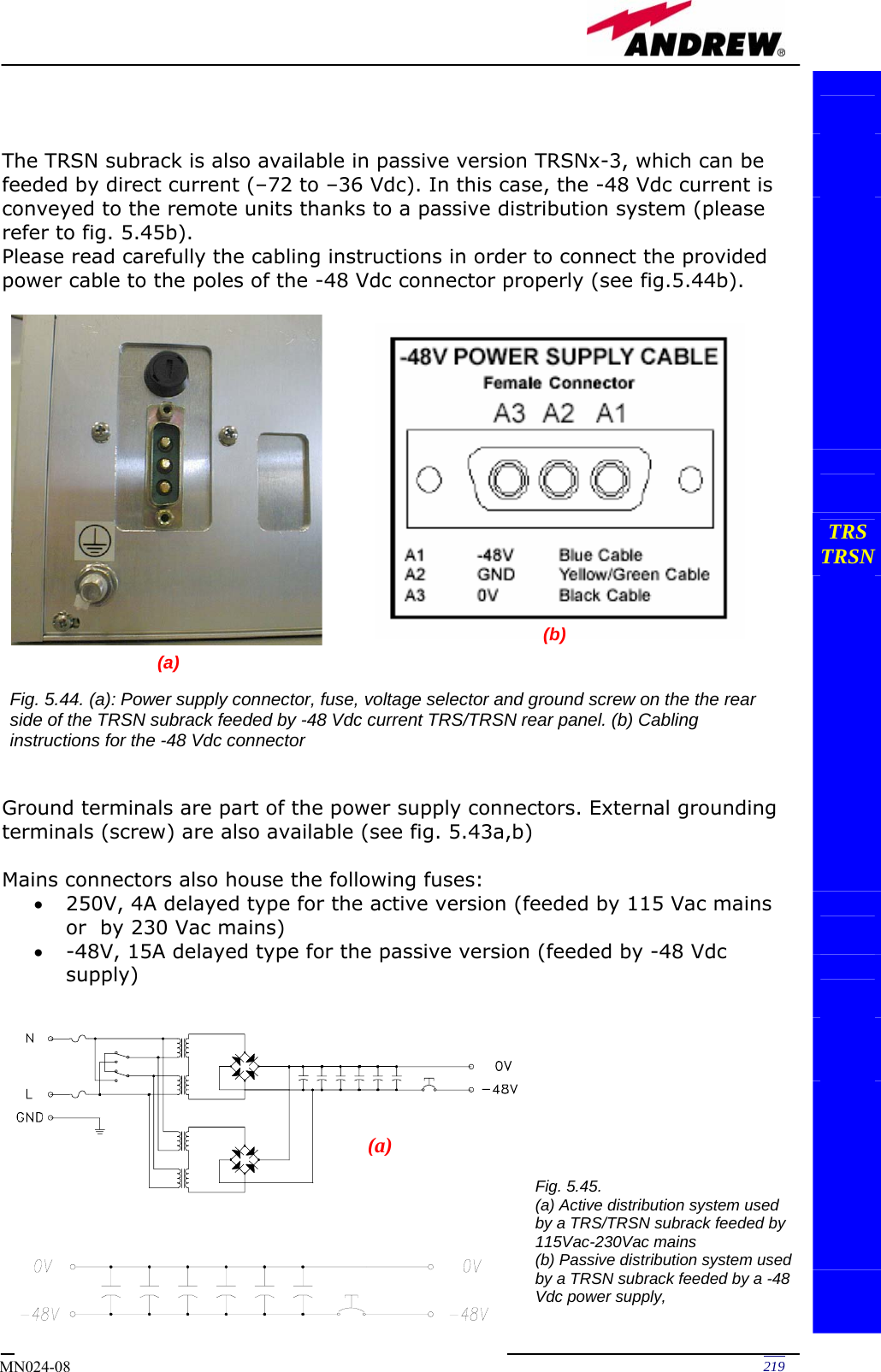
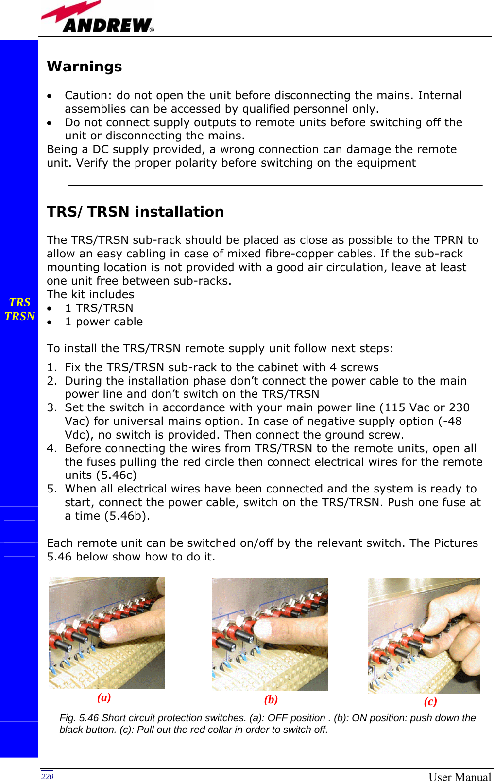
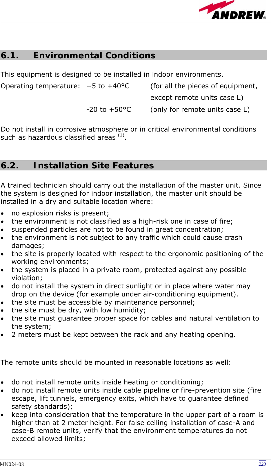
![118 User Manual Whichever baud rate you choose through dip-switch 5, remember that: • the same RS232 connection speed must be set up on the remote supervision unit • the baud rate which is selected through the dip-switch 5 sets the connection speed for both the RS232 port and the RS485 port as the TPRN uses both ports with the same rate. RS485 port The RS485 port consists of two RJ45 connectors, which can both work as input or output ports towards a RS485 bus. This RS485 bus has to be used in order to connect a multi sub-rack system to the remote supervision unit. In this case: • the TPRN sub-racks have to be connected one another via RS485 bus in a daisy chain; • In order to monitor the whole system, the remote supervision unit has to be connected to one of the TPRN sub-racks through RS232 port. Before connecting the TPRN sub-racks belonging to a multi-sub-rack system, remember to assign an exclusive binary address to each one. This is essential in order to let the supervision system recognize the different master units without any conflict. The binary address assignment can be done through dip-switches 1,2,3,4, which stand on interior TPRN backplane (see figure 5.6). A list of the correspondences between the addresses and the dip-switches is provided by table 5.2: simply note that dip-switch 1 is the least significant binary digit, while dip-switch 4 is the most significant one. Address Dip-switch 1 Dip-switch 2 Dip-switch 3 Dip-switch 4 0001 ON OFF OFF OFF 0010 OFF ON OFF OFF 0011 ON ON OFF OFF 0100 OFF OFF ON OFF 0101 ON OFF ON OFF 0110 OFF ON ON OFF 0111 ON ON ON OFF 1000 OFF OFF OFF ON 1001 ON OFF OFF ON 1010 OFF ON OFF ON 1011 ON ON OFF ON 1100 OFF OFF ON ON 1101 ON OFF ON ON 1110 OFF ON ON ON TPRN Baud rate [bps] Dip-switch 5 9600 OFF 19200 ON Table 5.1: Setting RS232 baud rate through dip-switch 5 Table 5.2: Dip-switches address settings](https://usermanual.wiki/Andrew-Wireless-Innovations-Group/TFAM1719.Manual-2/User-Guide-800096-Page-6.png)
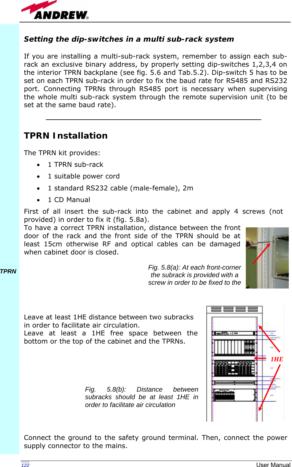

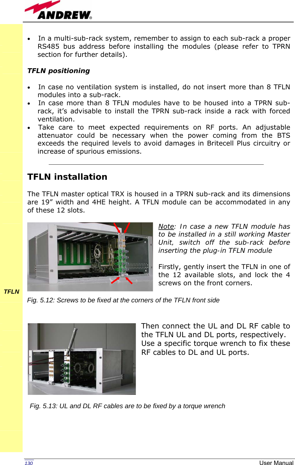

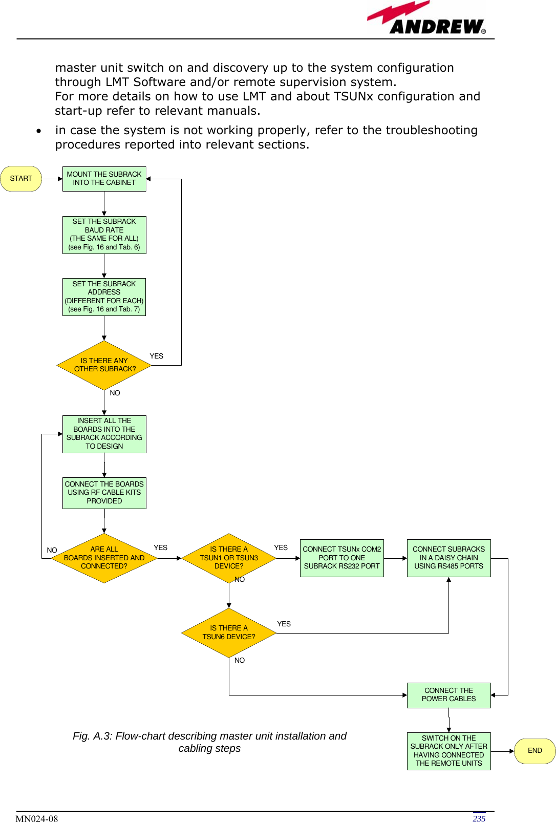
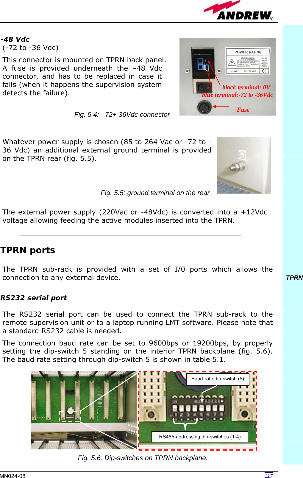
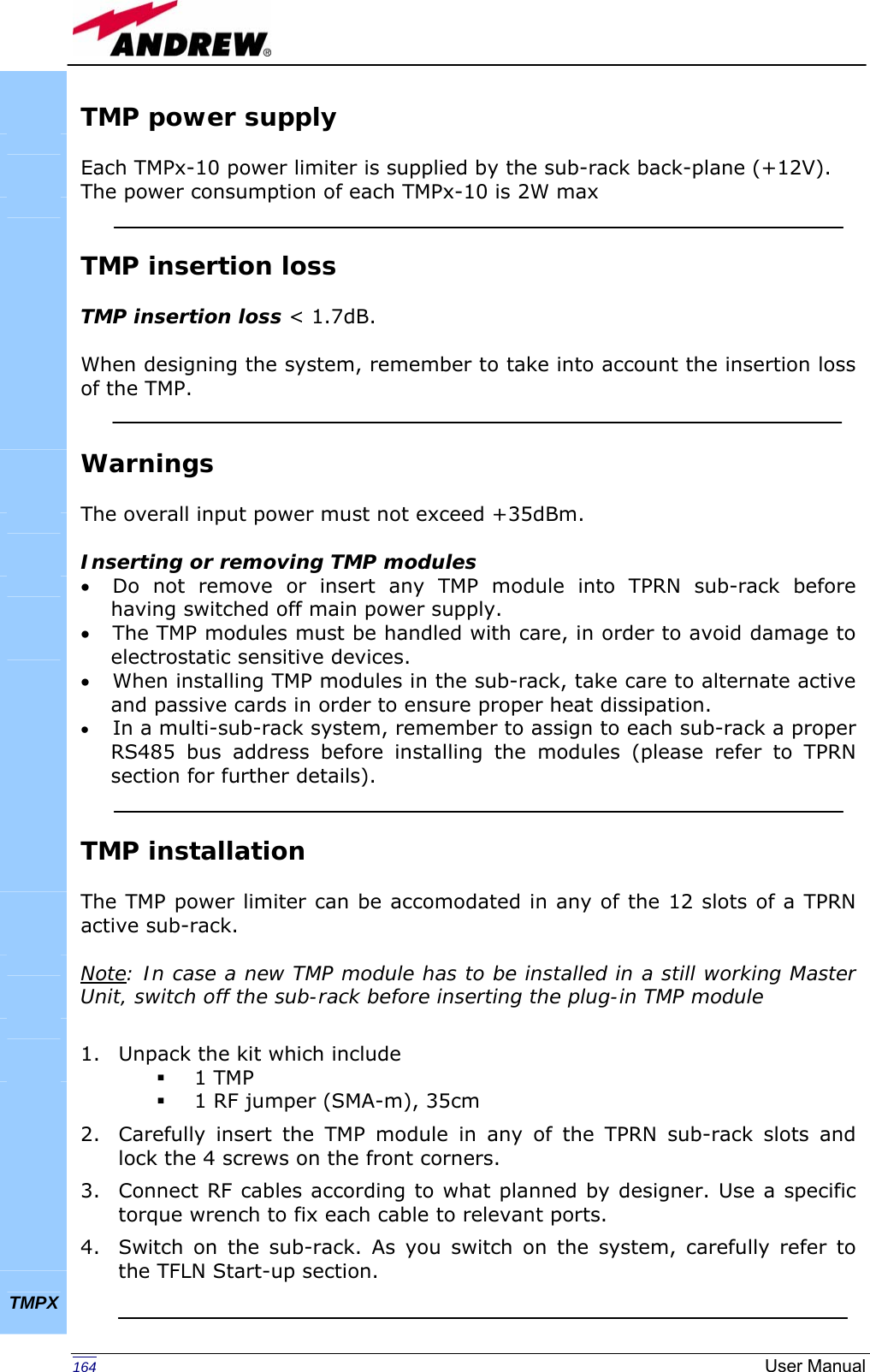
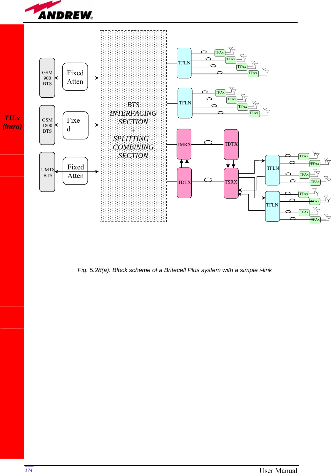
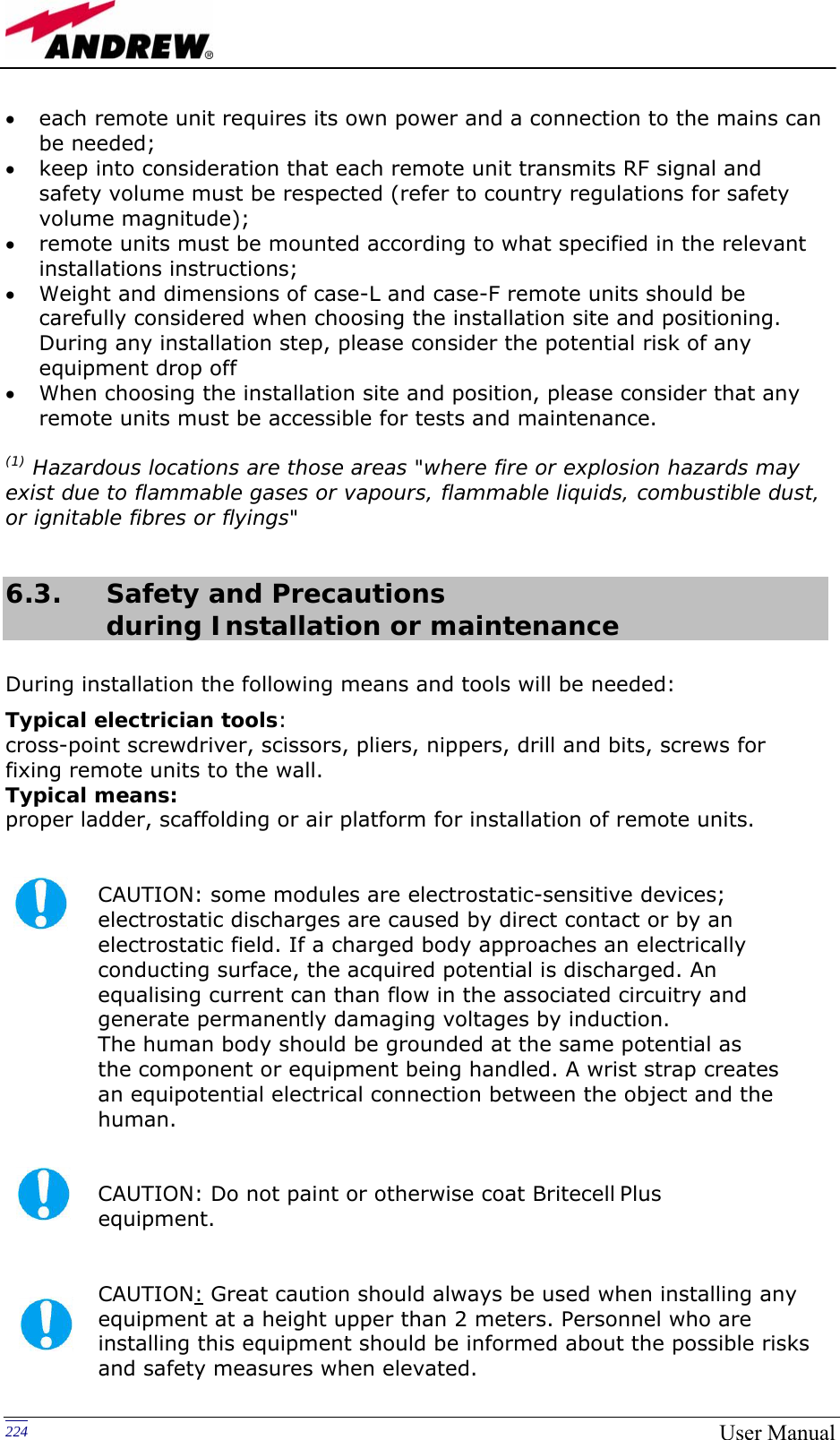
![135MN024-08 to the TFAx side, disconnect the optical SC-APC connector from TFAx UL port and measure the input power PIN(UL) coming out of the TFAx UL port. 5. Calculate the UL fibre attenuation AUL as: AUL [dB] = PIN(UL) – POUT(UL) a. If AUL > 4dB, the fibre optic cable has some problems or cable path is too long. Replace it. b. If AUL < 4dB, then TFAx remote unit should be faulty. Before replacing it, check the TFAx status on supervision system and contact for assistance TFLN](https://usermanual.wiki/Andrew-Wireless-Innovations-Group/TFAM1719.Manual-2/User-Guide-800096-Page-23.png)
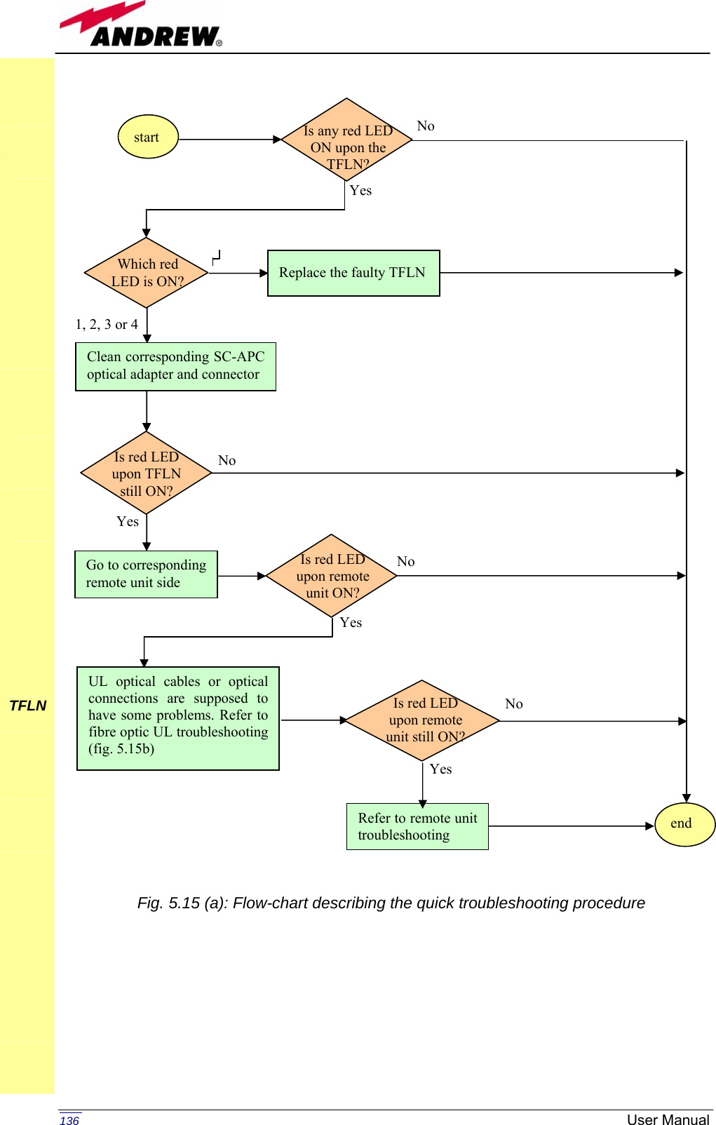
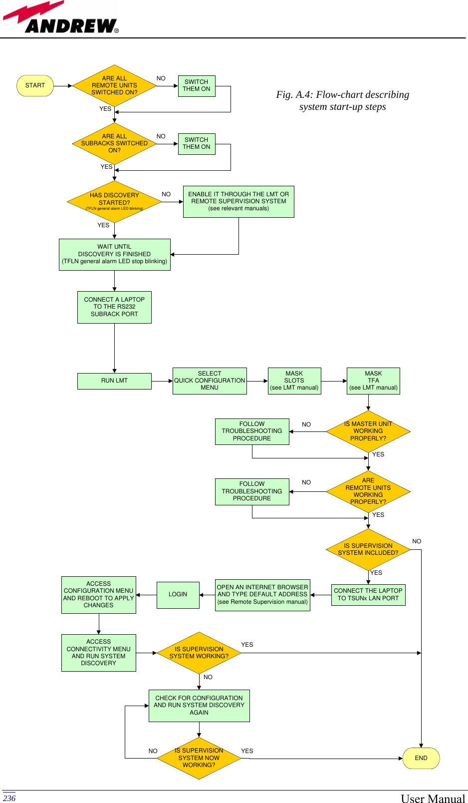
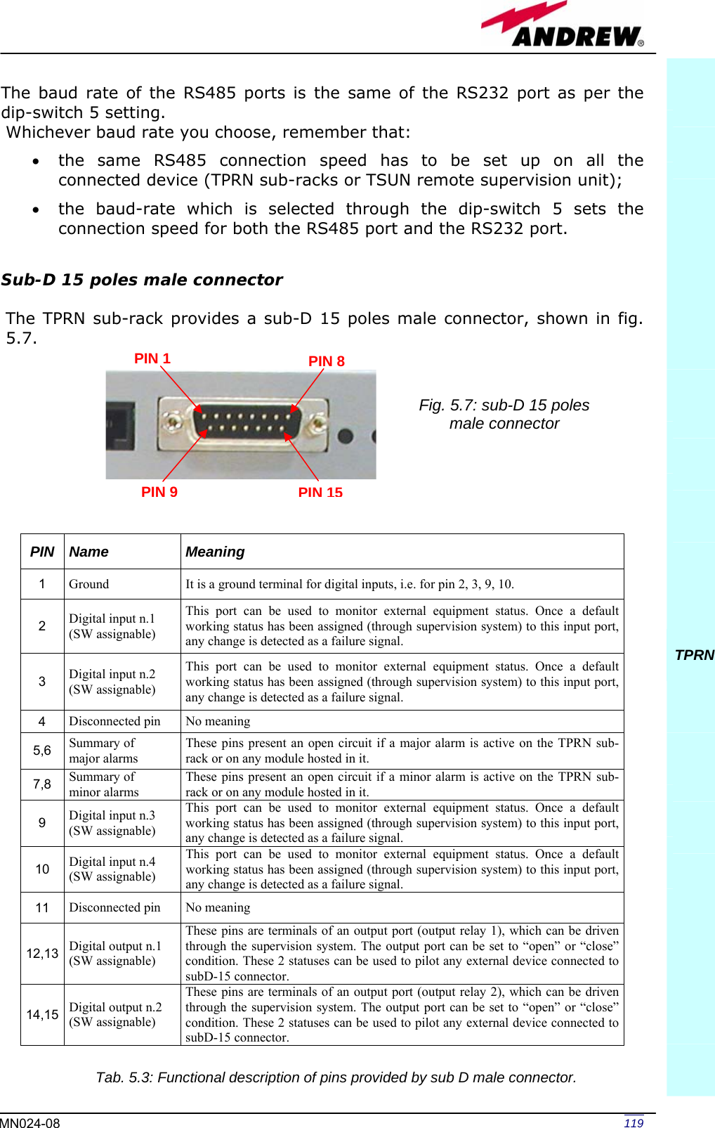
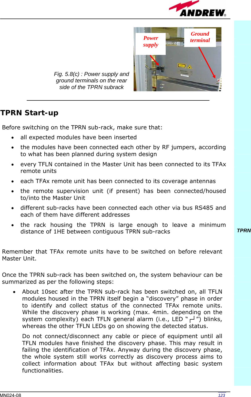
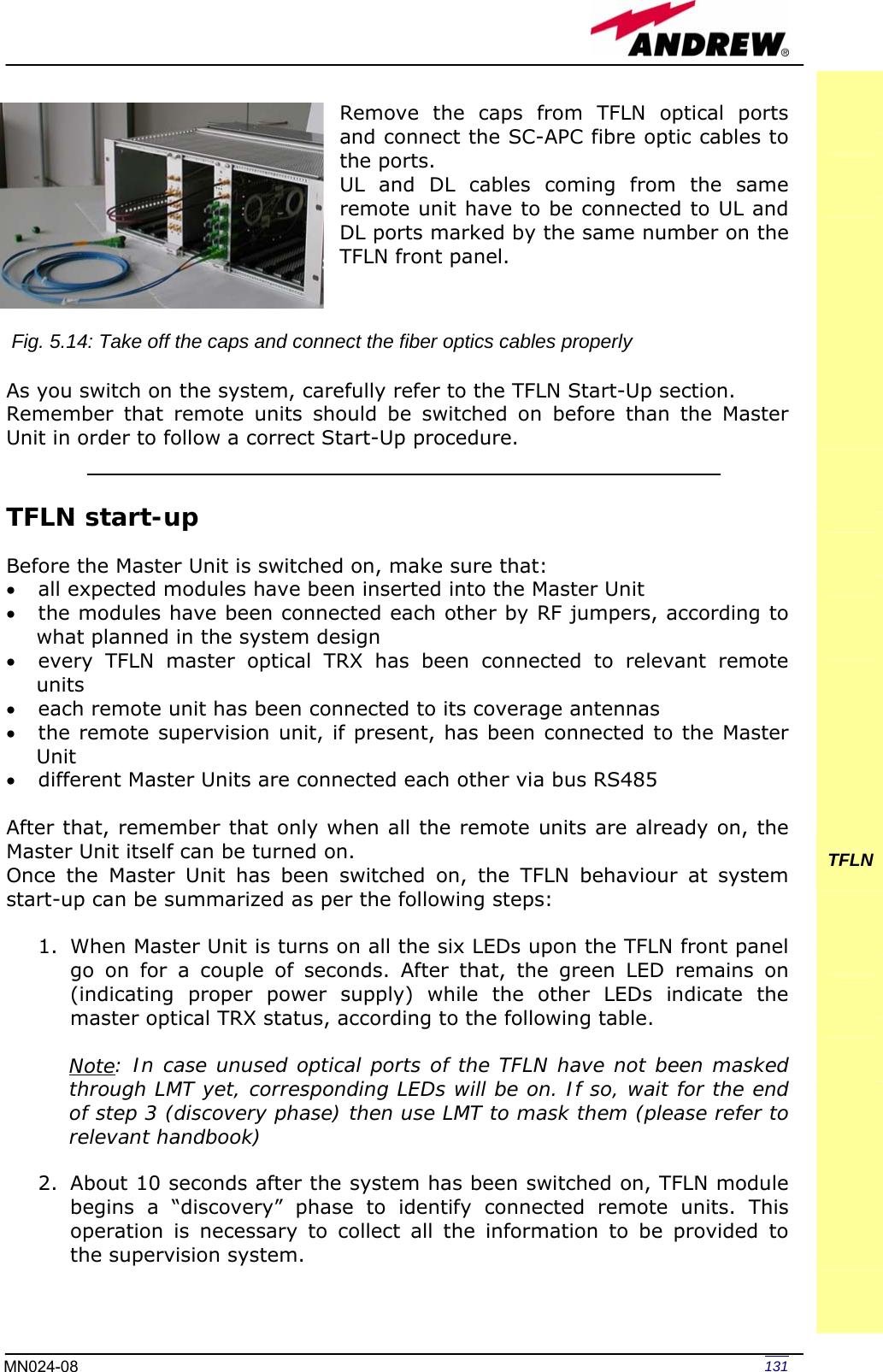
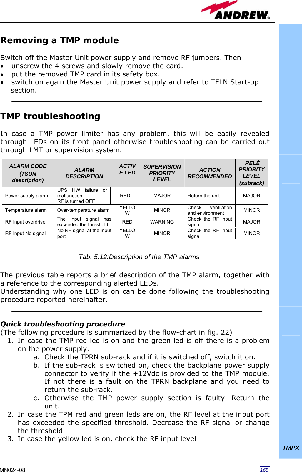
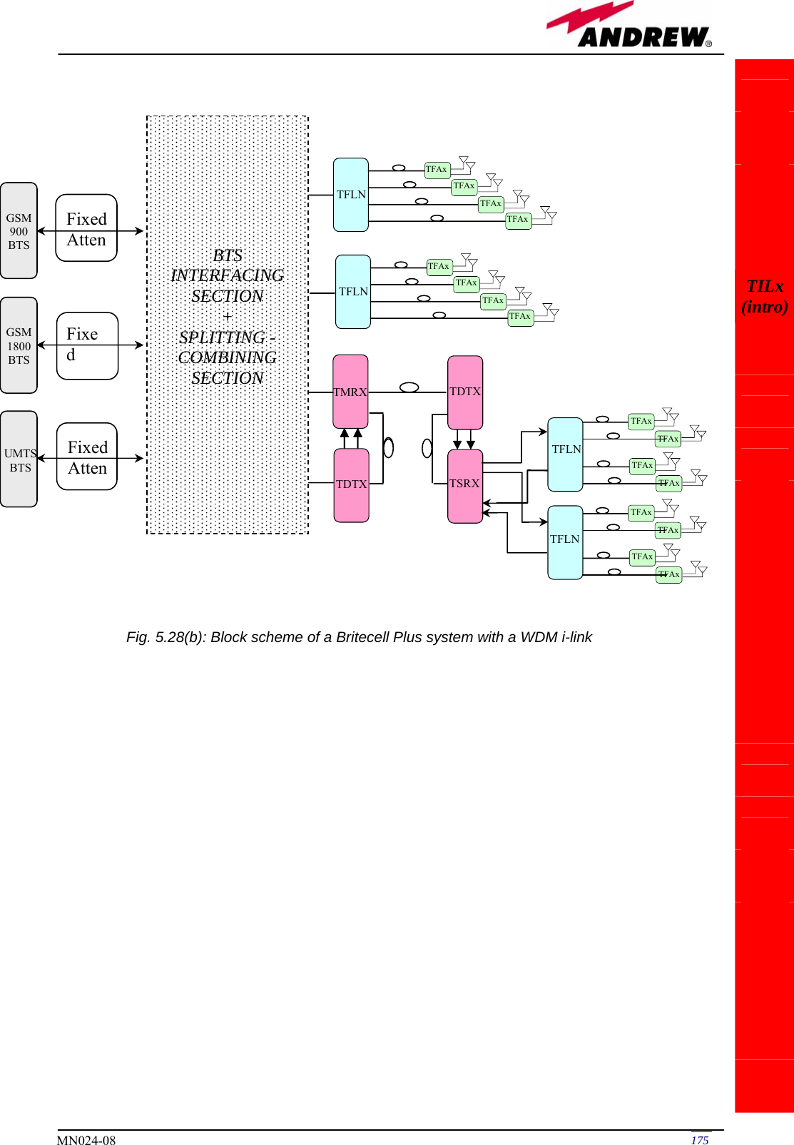
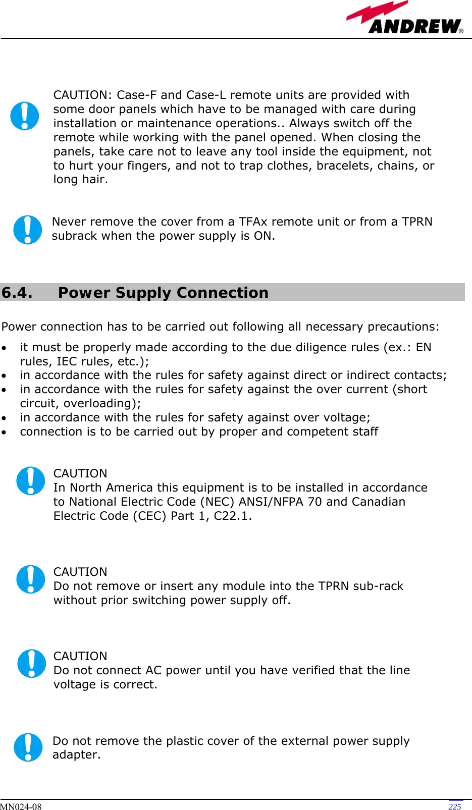
![137MN024-08 TFLN Fig. 5.15 (b): Flow-chart describing the fibre optic UL troubleshooting start Is there any small radius of curvature of the fibre? Rearrange the optical path in order to avoid sharp bends. If necessary replace the optical cable with a longer one. Is the red LED upon TFLN still ON? Are SC-APC connectors properly installed at both fibre ends? Fix SC-APC connectors properly to adapters. YesNo No YesNoYes No YesDisconnect the optical SC-APC connector from TFLN UL port. Clean the optical SC-APC ports both on TFLN and TFAx side. Disconnect the optical fibre and clean it at both ends. Re-connect the fibre to relevant ports. Measure the output power at the corresponding fibre end Measure the input power entering the fibre. Go to the TFAx side Disconnect the optical SC-APC connector from TFAx UL port. Calculate the UL fibre attenuation: AUL[dB]=input power - output power Is AUL > 4dB? Fibre optic cable has some problems. Replace it. The TFAx remote unit should be faulty. Before replacing it, verify its status through supervision system and contact for assistance. end No YesNo Yes Is the red LED upon TFLN still ON? Is the red LED upon TFLN still ON?](https://usermanual.wiki/Andrew-Wireless-Innovations-Group/TFAM1719.Manual-2/User-Guide-800096-Page-25.png)


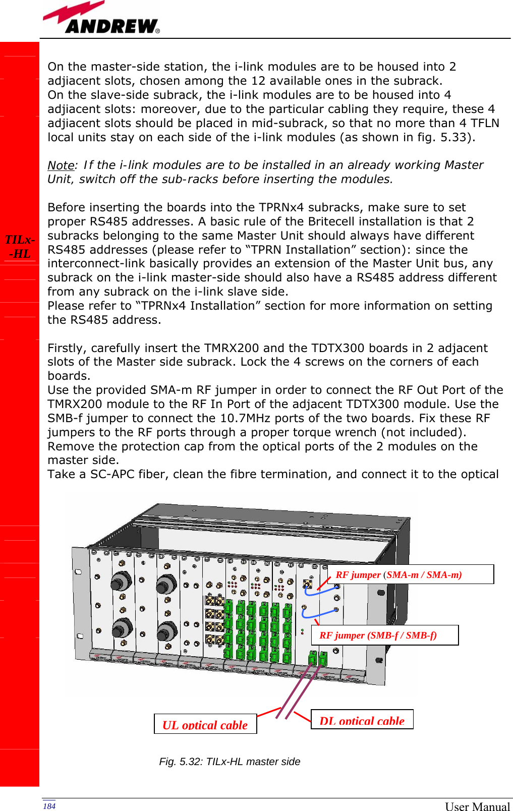
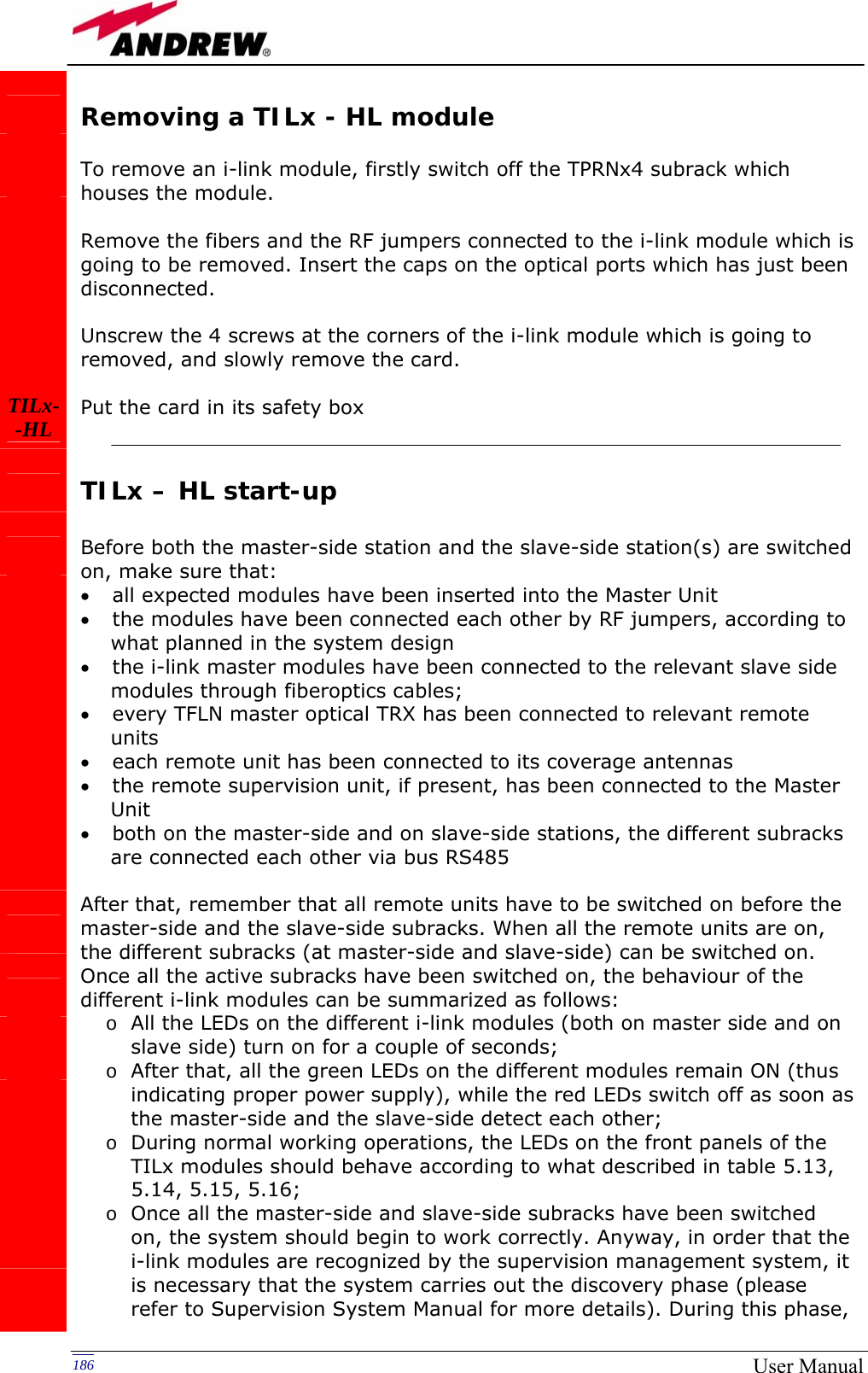
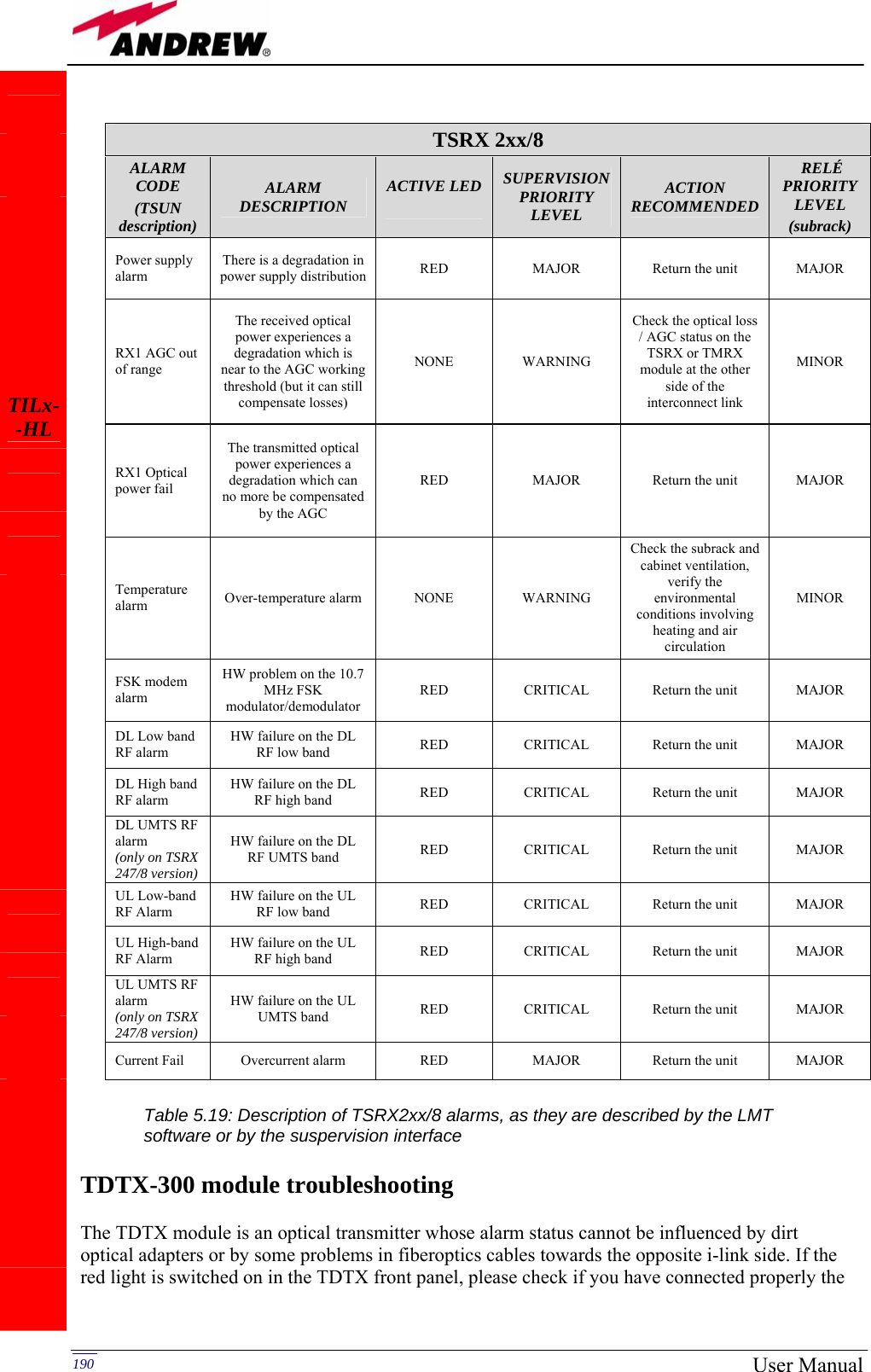
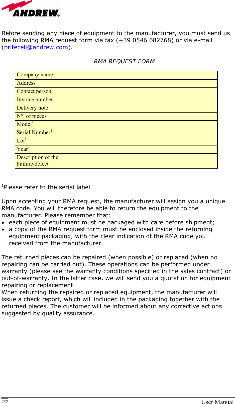
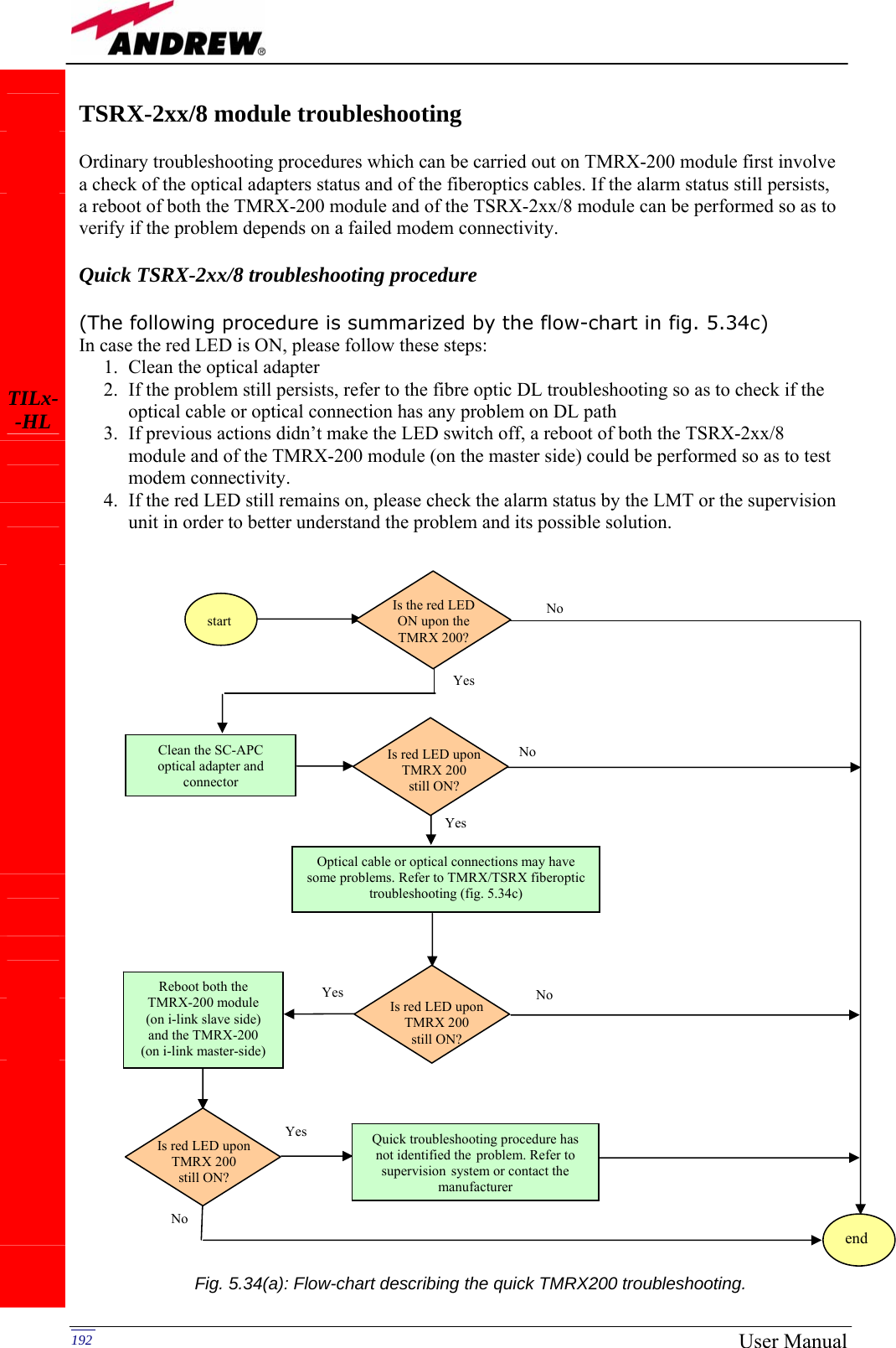
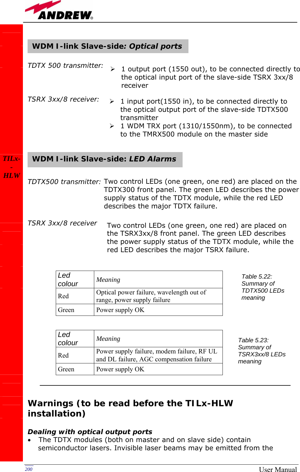
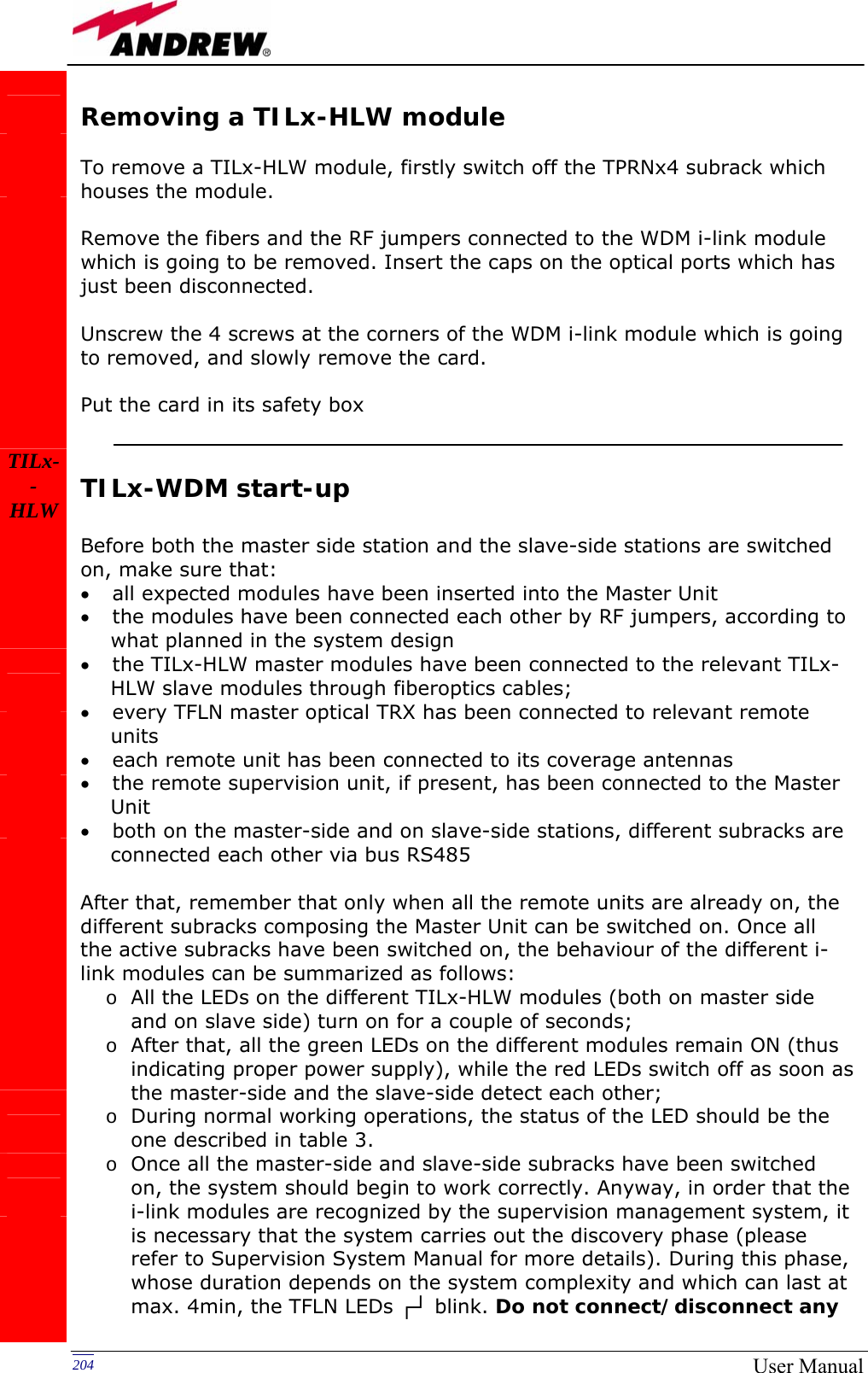
![191MN024-08 RF jumper. If the RF connection proves to be ok and the red LED keep on switching on, please contact the manufacturer. TMRX-200 module troubleshooting Ordinary troubleshooting procedures which can be carried out on TMRX-200 module first involve a check of the optical adapter status and of the fiberoptics cable. If the alarm status still persists, a reboot of both the TMRX-200 module and of the TSRX-2xx/8 module can be performed so as to re-inizialize the link. Quick TMRX-200 troubleshooting procedure (The following procedure is summarized by the flow-chart in fig. 5.34a) In case the red LED is ON, please follow these steps: 1. Clean the optical adapter 2. If the problem still persists, refer to the TMRX/TSRX fiber optic troubleshooting so as to check if the optical cable or optical connection has any problem on DL path 3. If previous actions didn’t make the LED switch off, a reboot of both the TMRX-200 module and of the TSRX-2xx/8 module (on the slave-side) could be performed so as to re-inizialize the link. 4. If the red LED still remains on, please check the alarm status by the LMT or the supervision unit in order to better understand the problem and its possible solution. TMRX/TSRX fiber optic troubleshooting (The following procedure is summarized by the flow-chart in fig. 5.34b) 1. Check if there is any point where fibre experiences a short radius of curvature. In this case, rearrange the optical path in order to avoid sharp bends (if necessary, replace the optical cable with a longer one). If TMRX (TSRX) red LED switches off, troubleshooting has been successfully carried out. Otherwise, follow next steps. 2. Check if SC-APC connectors are properly installed at both fibre ends. In case they are not, fix more firmly the SC-SPC connectors to their adapters. If the TMRX (TSRX) red LED switches off, troubleshooting has been successful. Otherwise, follow next steps. 3. Disconnect the optical fibre and clean it better at both ends, then clean also the relevant SC-APC adapters. Re-connect the fibre to relevant ports after cleaning. If it doesn’t make TMRX (TSRX) red LED switch off, follow next steps. 4. Disconnect the fiber from the TMRX (TSRX) port, and measure the power Pout which comes out from the fiber. Then, go to the module where the other end of the fiber is connected (it can be either on the slave side and on the master side, depending on the fiber or on the jumper you are verifying), disconnect it and measure the input power Pin coming out of the port. Calculate the fibre attenuation A due to the fiberoptics cable: Af [dB] = Pin – Pout a. If ADL > 10 dB, then the fibre optic cable has some problems. Replace it with a new one. b. If ADL < 10 dB troubleshooting procedure has not identified the problem. Refer to supervision system or contact the manufacturer for assistance. TILx--HL](https://usermanual.wiki/Andrew-Wireless-Innovations-Group/TFAM1719.Manual-2/User-Guide-800096-Page-79.png)
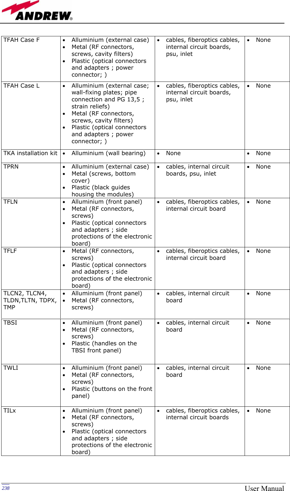
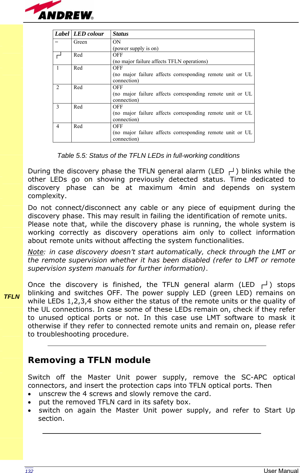
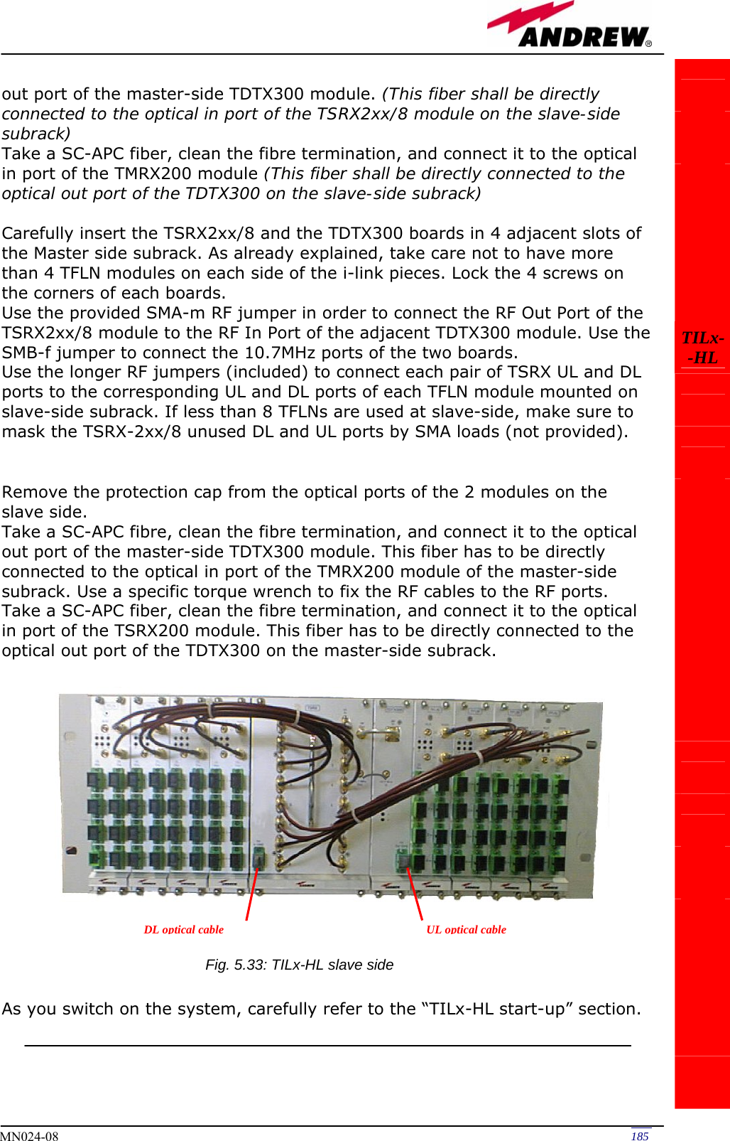
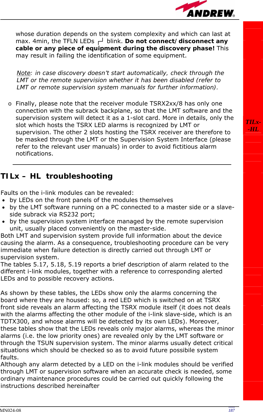
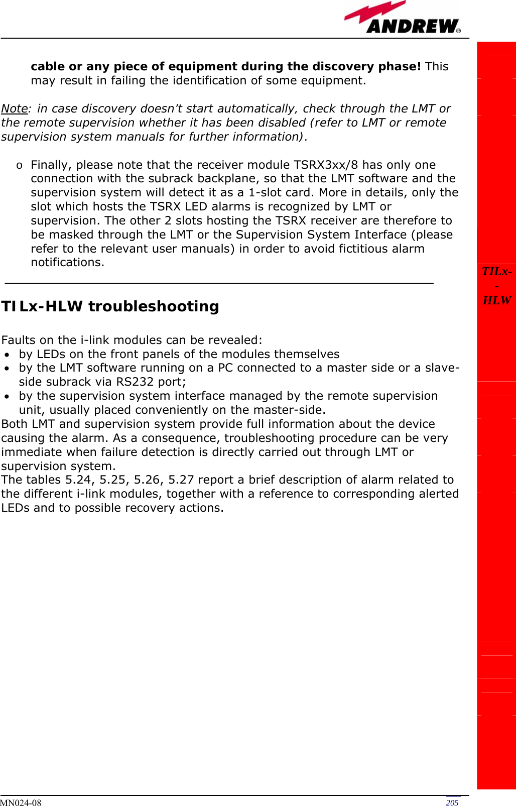
![193MN024-08 TILx--HL start Is there any point where the fibre experiences a small radius of curvature? Rearrange the optical path to avoid sharp bends. If necessary replace the optical cable with a longer one. Is red LED upon TMRX/TSRX still ON? Are SC-APC connectors properly installed at both fibre ends? Fix better SC-APC connectors Yes No No Yes No Yes No Yes Disconnect the optical SC-APC connector from TMRX/TSRX Clean the optical SC-APC ports corresponding to both the fiber ends Disconnect the fiber optic cable and clean it at both ends.Reconnect the fibre to relevant ports Measure the output power at corresponding fibre end. Connect the adapter againGo to the module where the other end of the fiber is connected, disconnect the corresponding SC-APC connector , and measure the corresponding input power. Then connect the adapter again. Calculate fibre attenuation A[dB]=input power - output power Is A > 10dB? Fibre optic cable has some problems. Replace it.Quick troubleshooting procedure has not identified any problem on the fiber optics cable end No Yes No Yes Is red LED upon TMRX/TSRX ON? Is red LED upon TMRX/TSRX still ON? Fig. 5.34(b): Flow-chart describing the TMRX/TSRX fiberoptic troubleshooting.](https://usermanual.wiki/Andrew-Wireless-Innovations-Group/TFAM1719.Manual-2/User-Guide-800096-Page-81.png)
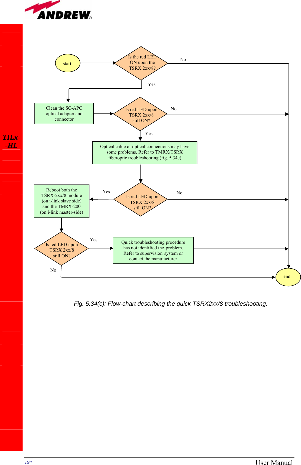
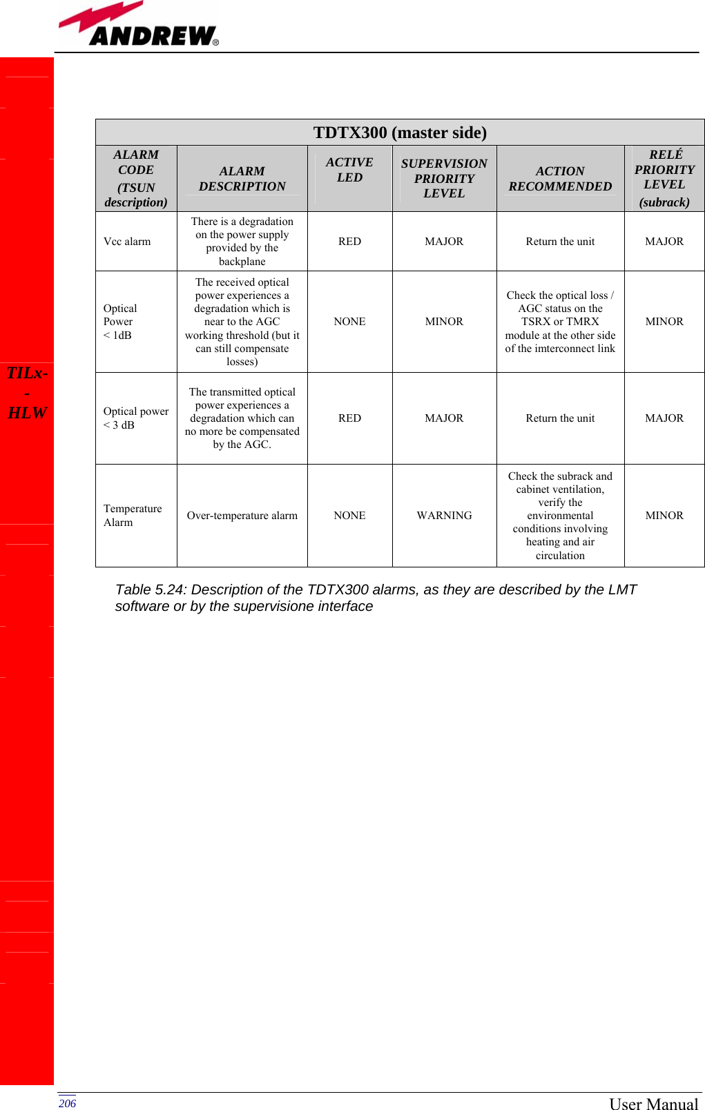
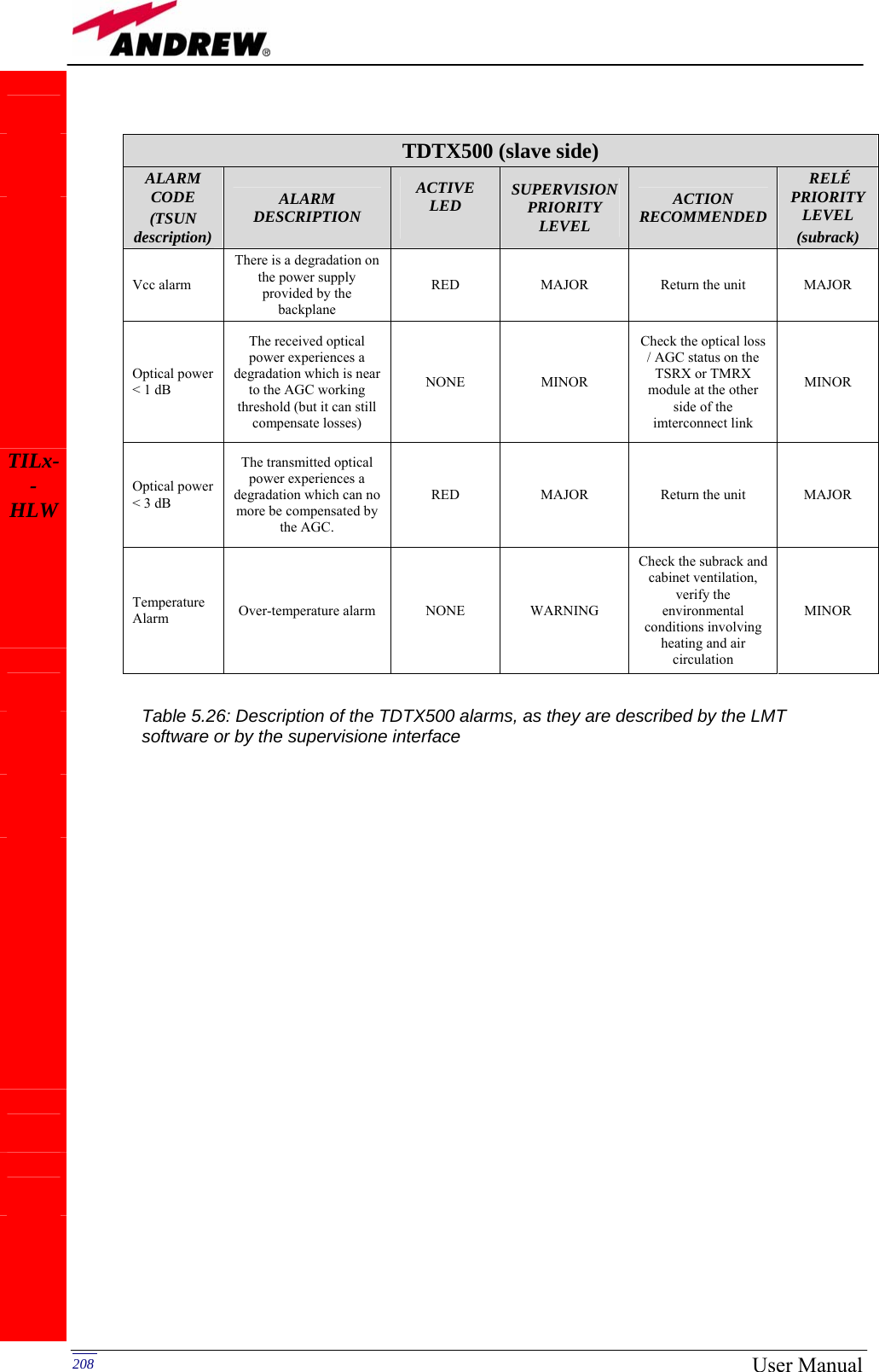
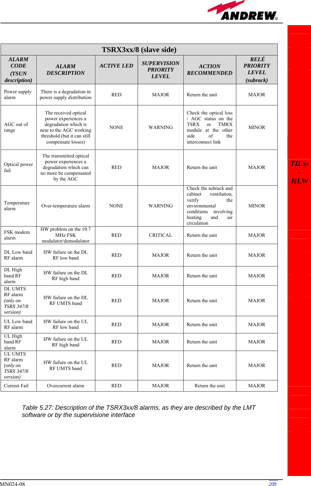
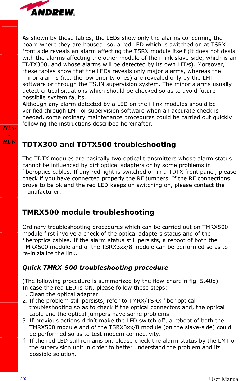
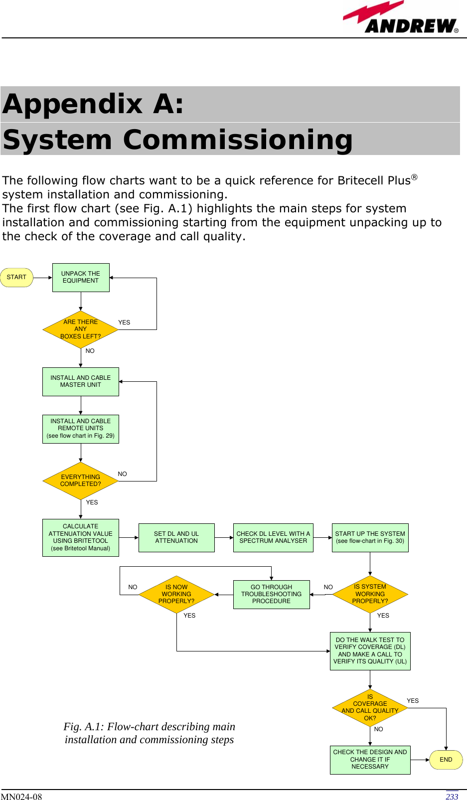
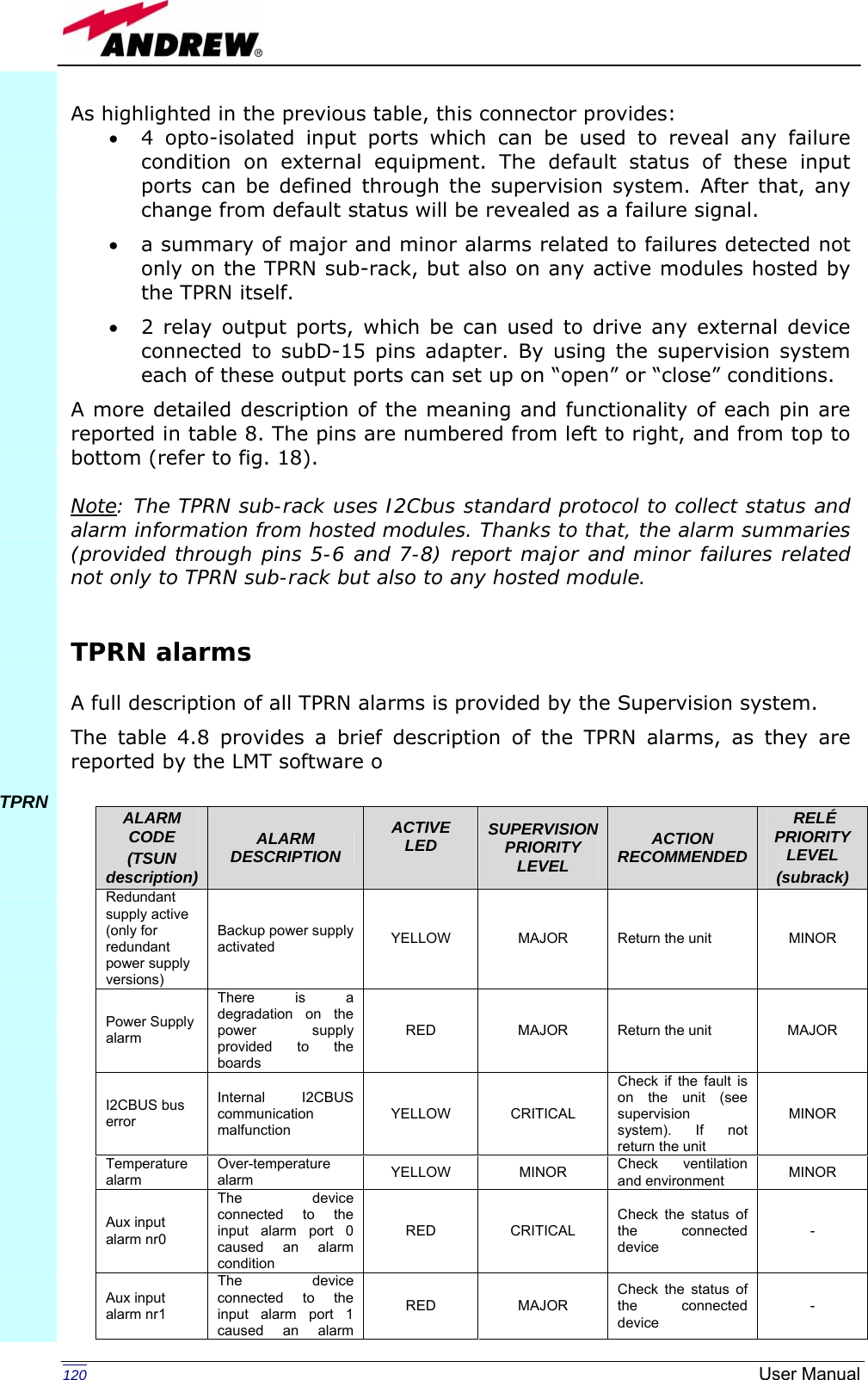
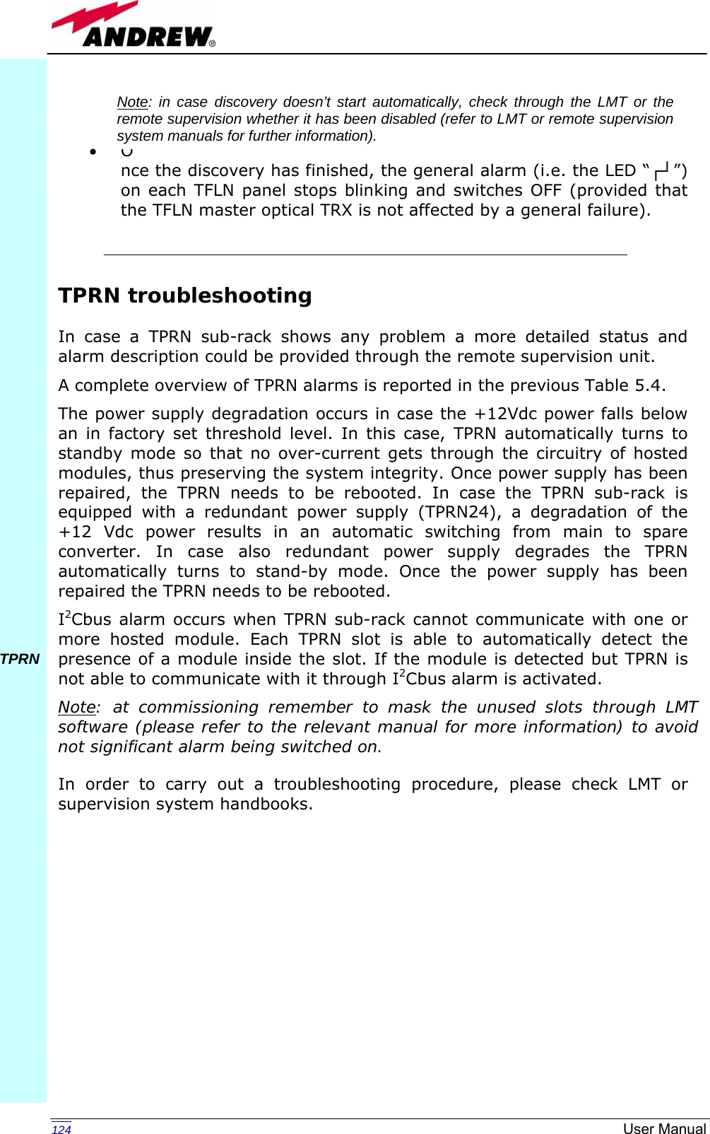
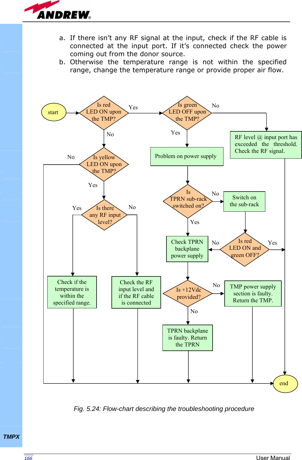
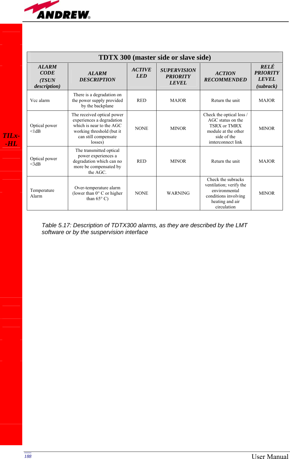
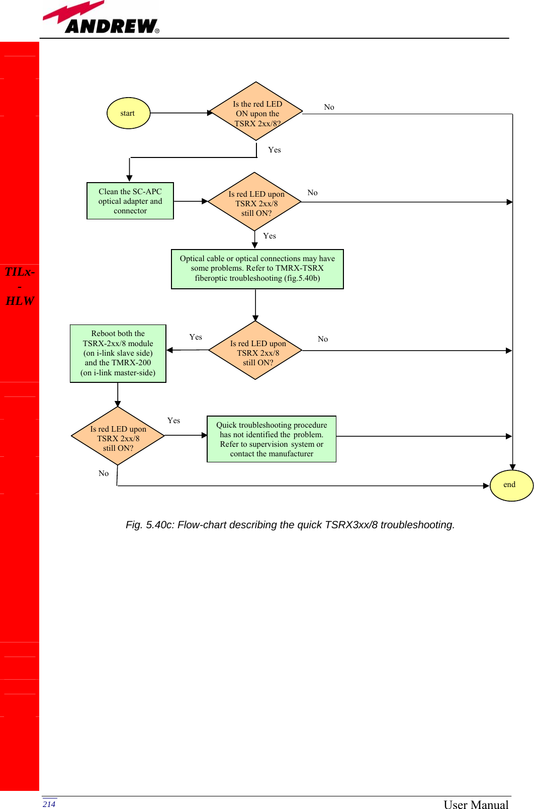
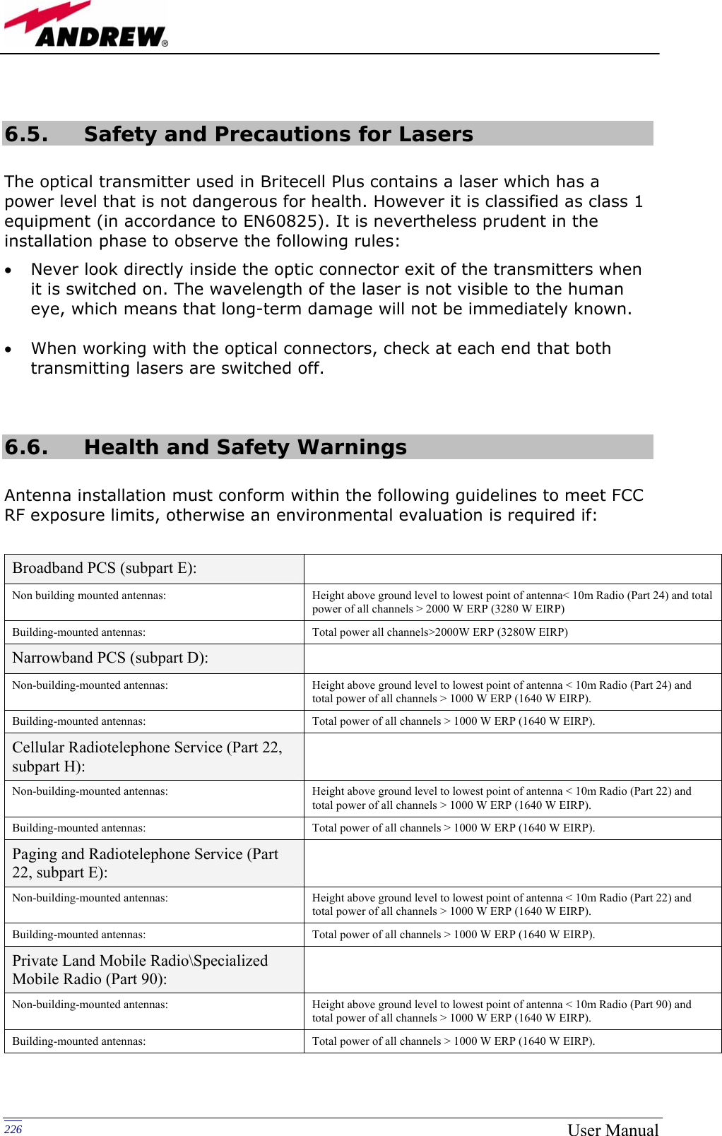
![211MN024-08 TMRX/TSRX fibre optic troubleshooting (The following procedure is summarized by the flow-chart in fig. 5.40b) 1. Check if there is any point where fibre experiences a short radius of curvature. In this case, rearrange the optical path in order to avoid sharp bends (if necessary, replace the optical cable with a longer one). If TMRX (TSRX) red LED switches off, troubleshooting has been successfully carried out. Otherwise, follow next steps. 2. Check if SC-APC connectors are properly installed at both fibre ends. In case they are not, fix more firmly the SC-SPC connectors to their adapters. If the TMRX (TSRX) red LED switches off, troubleshooting has been successful. Otherwise, follow next steps. 3. Disconnect the optical fibre and clean it better at both ends, then clean also the relevant SC-APC adapters. Re-connect the fibre to relevant ports after cleaning. If it doesn’t make TMRX (TSRX) red LED switch off, follow next steps. 4. Disconnect the fiber from the TMRX (TSRX) port, and measure the power Pout which comes out from the fiber. Then, go to the module where the other end of the fiber is connected (it can be either on the slave side and on the master side, depending on the fiber or on the jumper you are verifying), disconnect it and measure the input power Pin coming out of the port. Calculate the fibre attenuation A due to the fiberoptics cable: Af [dB] = Pin – Pout a. If Af > 10 dB, then the fibre optic cable has some problems. Replace it with a new one. b. If Af < 10 dB troubleshooting procedure has not identified the problem. Refer to supervision system or contact the manufacturer for assistance. TSRX3xx/8 module troubleshooting Ordinary troubleshooting procedures which can be carried out on TMRX200 module first involve a check of the optical adapters status and of the fiberoptics cables. If the alarm status still persists, a reboot of both the TMRX-500 module and of the TSRX3xx/8 module can be performed so as to re-inizialize the link. Quick TSRX3xx/8 troubleshooting procedure In case the red LED is ON, please follow these steps: 1. Clean the optical adapter 2. If the problem still persists, refer to the fibre optic troubleshooting so as to check if the optical cable or optical connection has any problem. 3. If previous actions didn’t make the LED switch off, a reboot of both the TSRX3xx/8 module and of the TMRX500 module (on the master side) could be performed so as to test modem connectivity. 4. If the red LED still remains on, please check the alarm status by the LMT or the supervision unit in order to better understand the problem and its possible solution. TILx--HLW](https://usermanual.wiki/Andrew-Wireless-Innovations-Group/TFAM1719.Manual-2/User-Guide-800096-Page-99.png)
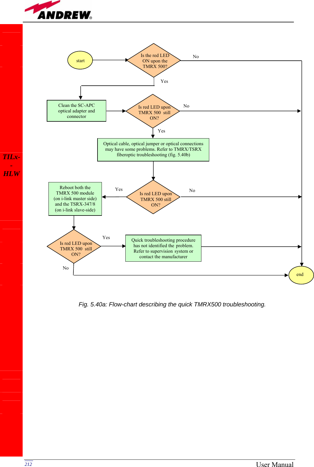
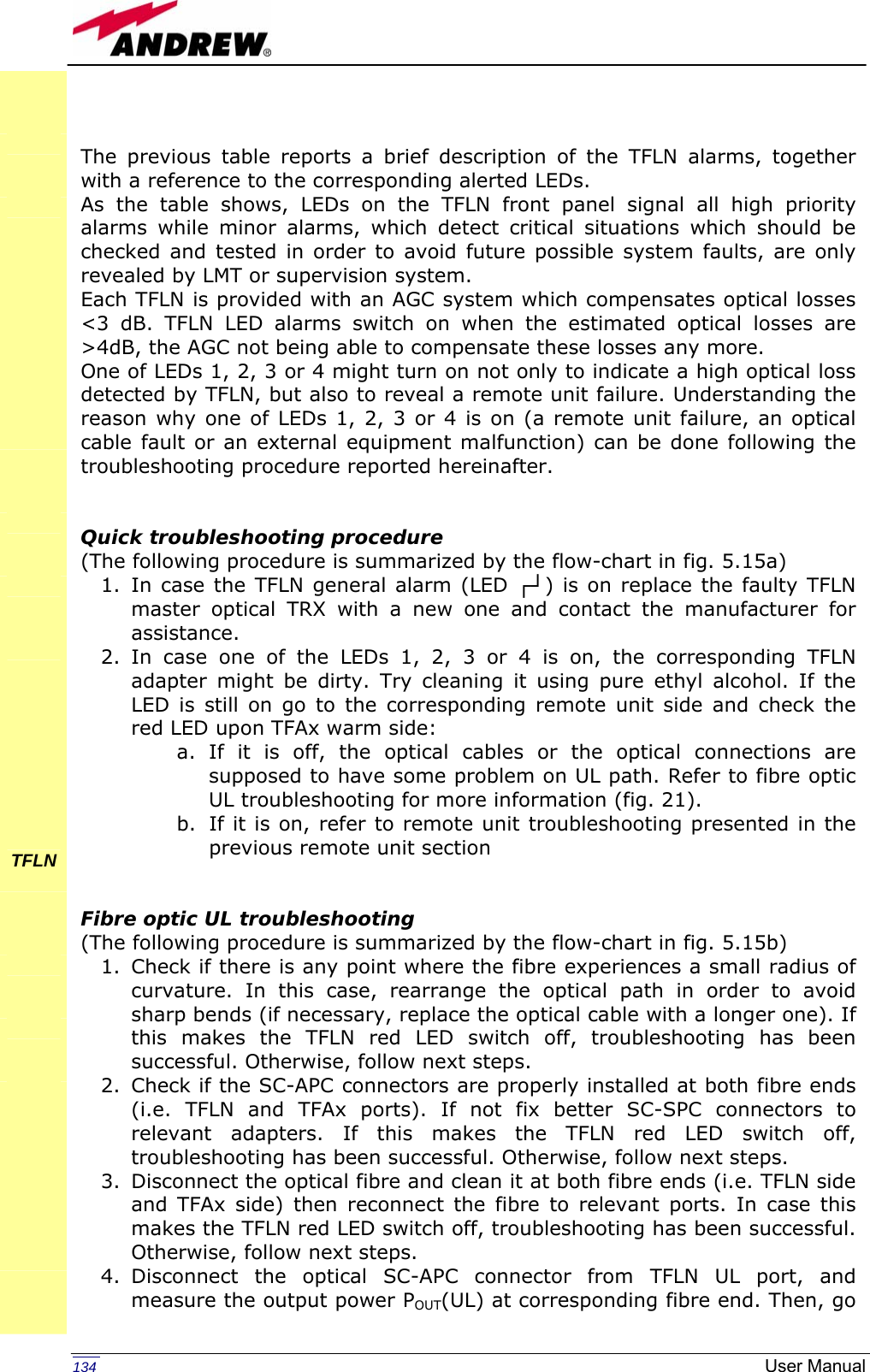
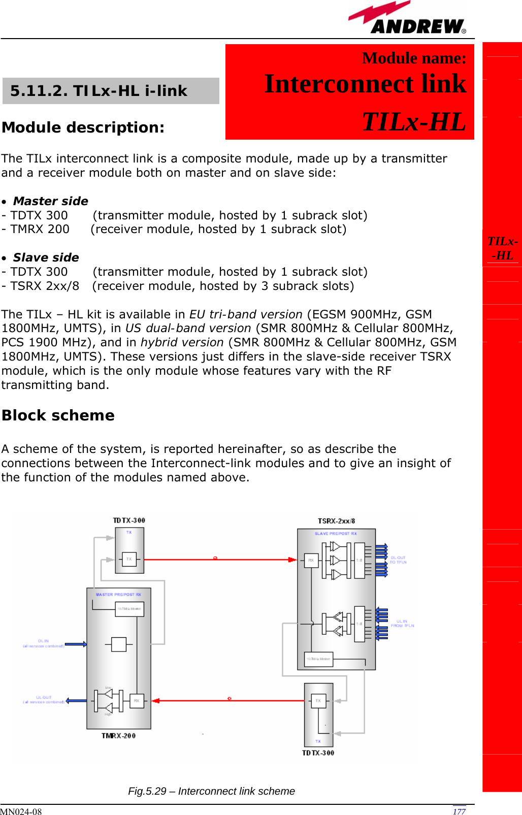
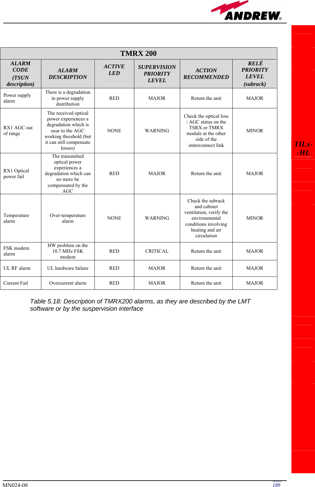
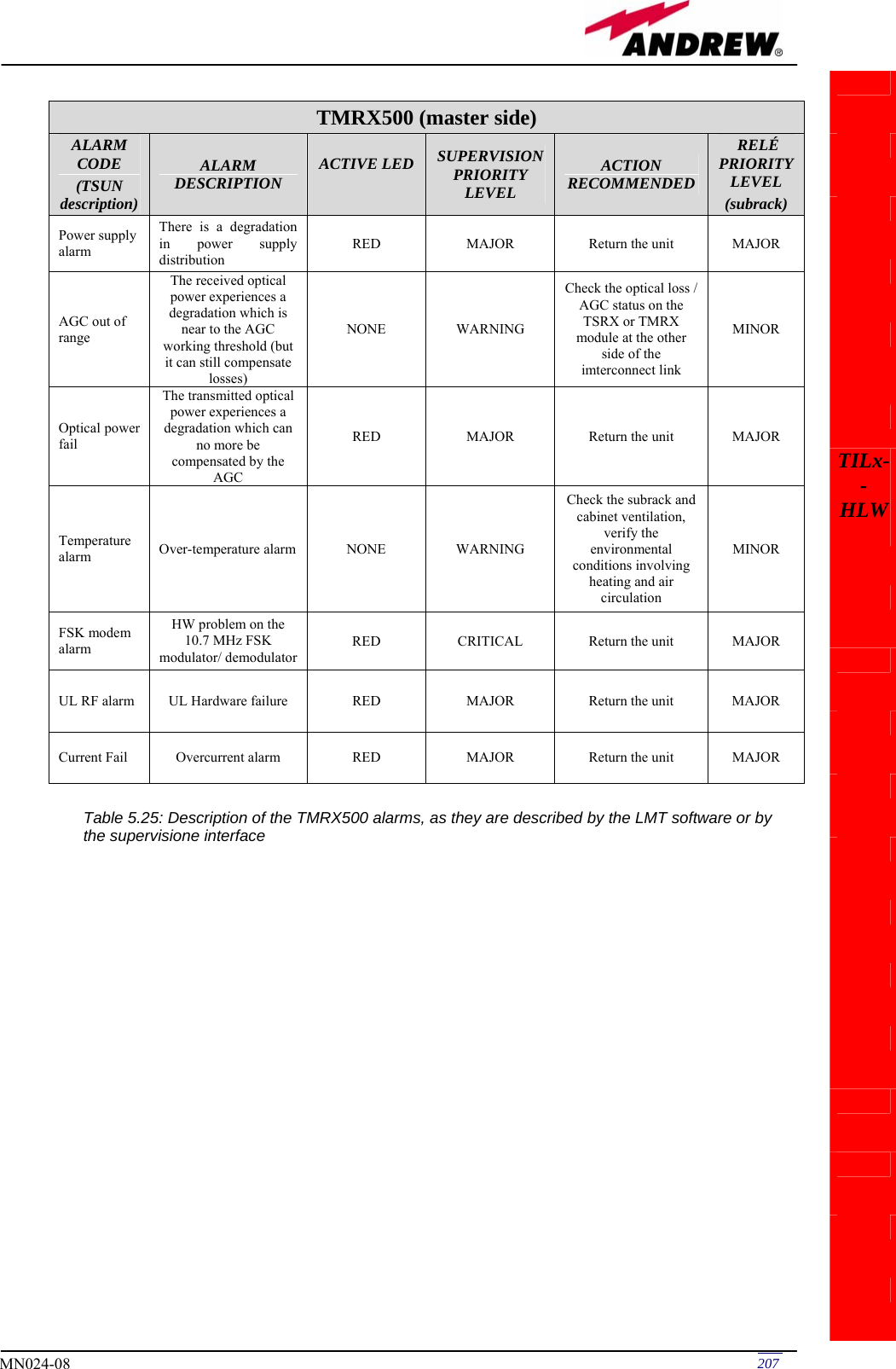
![213MN024-08 TILx--HLW Fig. 5.40b: Flow-chart describing the TMRX/TSRX fiberoptic troubleshooting. start Is there any point where the fibre experiences a small radius of curvature? Rearrange the optical path to avoid sharp bends. If necessary replace the optical cable with a longer one. Is red LED upon TMRX/TSRX still ON? Are SC-APC connectors properly installed at both fibre ends? Fix better SC-APC connectors Yes No No Yes No Yes No Yes Disconnect the optical SC-APC connector from TMRX/TSRX Clean the optical SC-APC ports corresponding to both the fiber ends Disconnect the fiber optic cable and clean it at both ends. Reconnect the fibre to relevant ports Measure the output power at corresponding fibre end. Connect the adapter againGo to the module where the other end of the fiber is connected, disconnect the corresponding SC-APC connector , and measure the corresponding input power. Then connect the adapter again. Calculate fibre attenuation A[dB]=input power - output power Is A > 10dB? Fibre optic cable has some problems. Replace it.Quick troubleshooting procedure has not identified any problem on the fiber optics cable end No Yes No Yes Is red LED upon TMRX/TSRX ON? Is red LED upon TMRX/TSRX still ON?](https://usermanual.wiki/Andrew-Wireless-Innovations-Group/TFAM1719.Manual-2/User-Guide-800096-Page-101.png)

![228 User Manual(please note that, if regulations only define the maximum electrical field strength and the maximum magnetic field strength, the allowed power density can be obtained as: S= E2/377= B2·377, where 377 is the characteristics impedance of the empty space). Example 1. Let’s suppose to use a High Power TFAH20 to distribute CDMA signals through a directional antenna, feeded by a 2-metre length RG223 cable (no splitters used). Let’s suppose the antenna gain is 7 dB. Let’s assume, moreover, that the maximum allowed power density we have to comply with is: S = 10 W m-2 (typical ICNIRP reference level for general public exposure to time-varying electric and magnetic fields). By reading the Britecell bulletin, we know that the output power P at the TFAH20 antenna port is 37 dBm (=5.012 W). By reading the cable specs, we get that RG223 cable losses can be estimated as 0.55 dB/m. Total losses between the TFAH20 output port and the antenna input port can therefore be estimated as follows: L = 0.55 (dB/m) x 2 (m) = 1.1 dB By replacing the above values of G, L, P, S parameters inside the relation 6.1, we therefore get the the following minimum safety distance from the antenna: rmin = { 10 · exp [ (7 - 1.1) / 10 ] · 5.012} / (4·π·10) } · exp (-1/2) = 0.394 m Example 2. Let’s suppose to use a Low Power TFAM85/19 through a directional antenna, feeded by a 5 -metre length RG223 cable with a 2-way splitter. Let’s suppose that the antenna Gain is 7 dB and that our Britecell system distributes one Cellular800 carrier and one PCS 1900. Let’s assume that the maximum allowed power density we have to comply with is: S = 50 W·m2 (typical ICNIRP reference level for occupational exposure to time-varying electric and magnetic fields) By reading the Britecell bulletin, we know that the output power per carrier at the TFAM antenna port is 21 dBm (=0.126 W) for the Cellular 850 MHz frequency band, and 20 dBm (0.1 W) in the PCS 1900 MHz frequency band. The total output power at the antenna port is therefore P = 0.126 + 0.1 = 0.226 W. Let’s assume that the splitter insertion losses are 3.5 dB. By reading the cable specs, we get that RG223 cable losses can be estimated as 0.55 dB/m. Total losses between the TFAM85/19 output port and antenna input port can therefore be estimated as follows: L = 0.55 (dB/m) x 5 (m) + 3.5 = 5.25 dB By replacing the above values of G, L, P, S parameters inside the relation 6.1, we therefore get the the following minimum safety distances from the antenna:](https://usermanual.wiki/Andrew-Wireless-Innovations-Group/TFAM1719.Manual-2/User-Guide-800096-Page-116.png)
![229MN024-08 rmin = { 10 · exp [ (7 - 5.25) / 10 ] · 0.226} / (4·π·50) } · exp (-1/2) = 0.023 m Example 3. Let’s suppose to have a Low Power TFAM90/20 connected to an omnidirectional antenna through a 20-metre length ½” cable (no splitters used). Let’s suppose that the antenna Gain is 7 dB and that our Britecell system distributes two GSM900 carriers and one UMTS2100 carrier. Moreover, let’s assume that the maximum allowed electrical field strength is: E = 6 V m (typical Italian reference level for exposure to time-varying electric and magnetic fields). The corresponding value of the maximum allowed power density is: S = E2 /377 = 0.1 W/m2 By reading the Britecell bulletin, we get that the output power at the TFAM antenna port is 14 dBm/carrier (=0.025 W) for a 2-carrier GSM900 MHz distribution, and 17 dBm (0.05 W) for 1 WCDMA carrier. The 900 MHz and 2100 MHz output powers at the remote unit ports are: P900MHz,TFAx = 0.025W+0.025W=0.05W (for 900MHz signals) P2100MHz,TFAx= 0.05W (for 2100MHz signals) Let’s assume that the ½” cable losses are 0.07 dB/m in the 900 MHz band and 0.18 dB/m in the 2100 MHz band; the total losses between the TFAM90/20 output port and the antenna input ports can therefore be estimated as follows: L900MHz = 0.07 (dB/m) x 10 (m) = 0.7 dB on 900MHz signals L2100MHz=0.18 (dB/m) x 10 (m) =1.8 dB on 2100MHz signals The term “10 exp (G-L/10) P” which appears inside the relation 6.1 should therefore be calculated apart for each frequence, and then added in order to calculate the composite contribution: P900MHz, ant = 10 exp[(7-0.7)/10]· 0.05 = 0.213 W P2100MHz,ant = 10 exp[(7-1.8)/10]·0.05 = 0.165 W Pcomposite= P900MHz, ant + P2100MHz,ant= 0.378W By dividing the total power through (4·π·S) and taking the square root according to the relation 6.1, we therefore get the the following minimum safety distances from the antenna: rmin = { Pcomposite /(4·π·0.1)} · exp (-1/2) = 0.54 m](https://usermanual.wiki/Andrew-Wireless-Innovations-Group/TFAM1719.Manual-2/User-Guide-800096-Page-117.png)