Andrew Wireless System CAPL17E23 ION-E Remote Unit for cellular systems User Manual M0201AAA
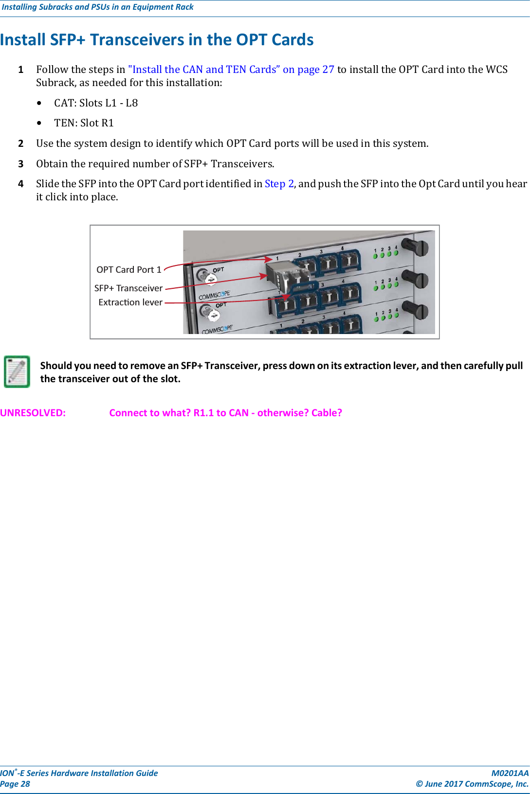
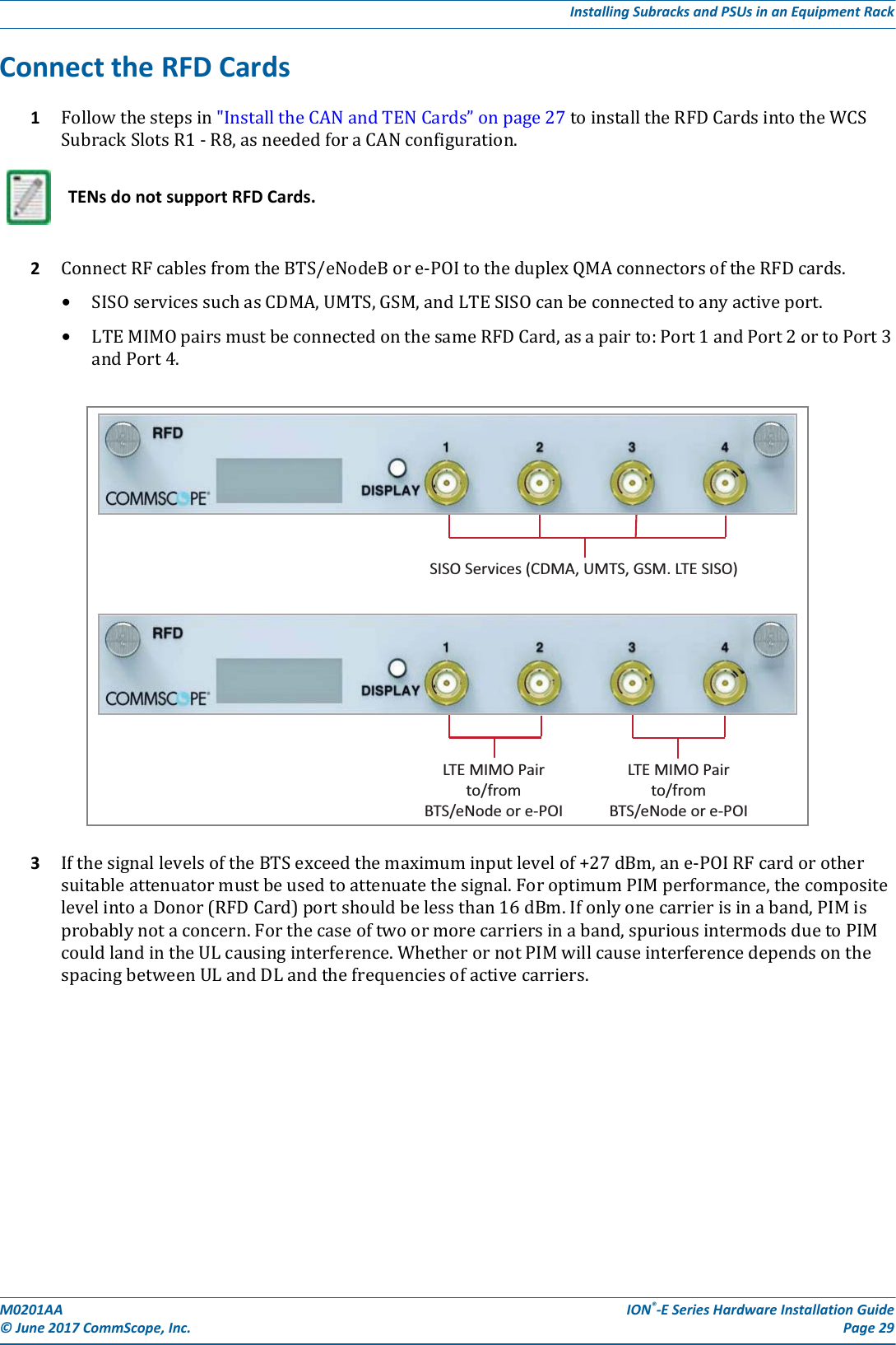
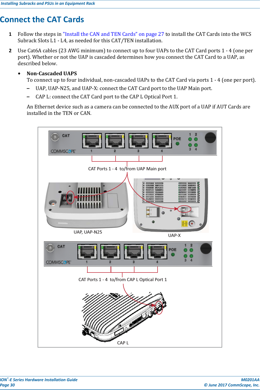
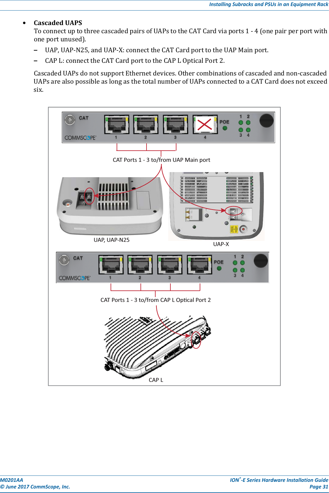
Andrew Wireless System ION-E Remote Unit for cellular systems M0201AAA
Contents
- 1. users manual part 1
- 2. users manual part 2
- 3. users manual part 3
- 4. installation manual
users manual part 1


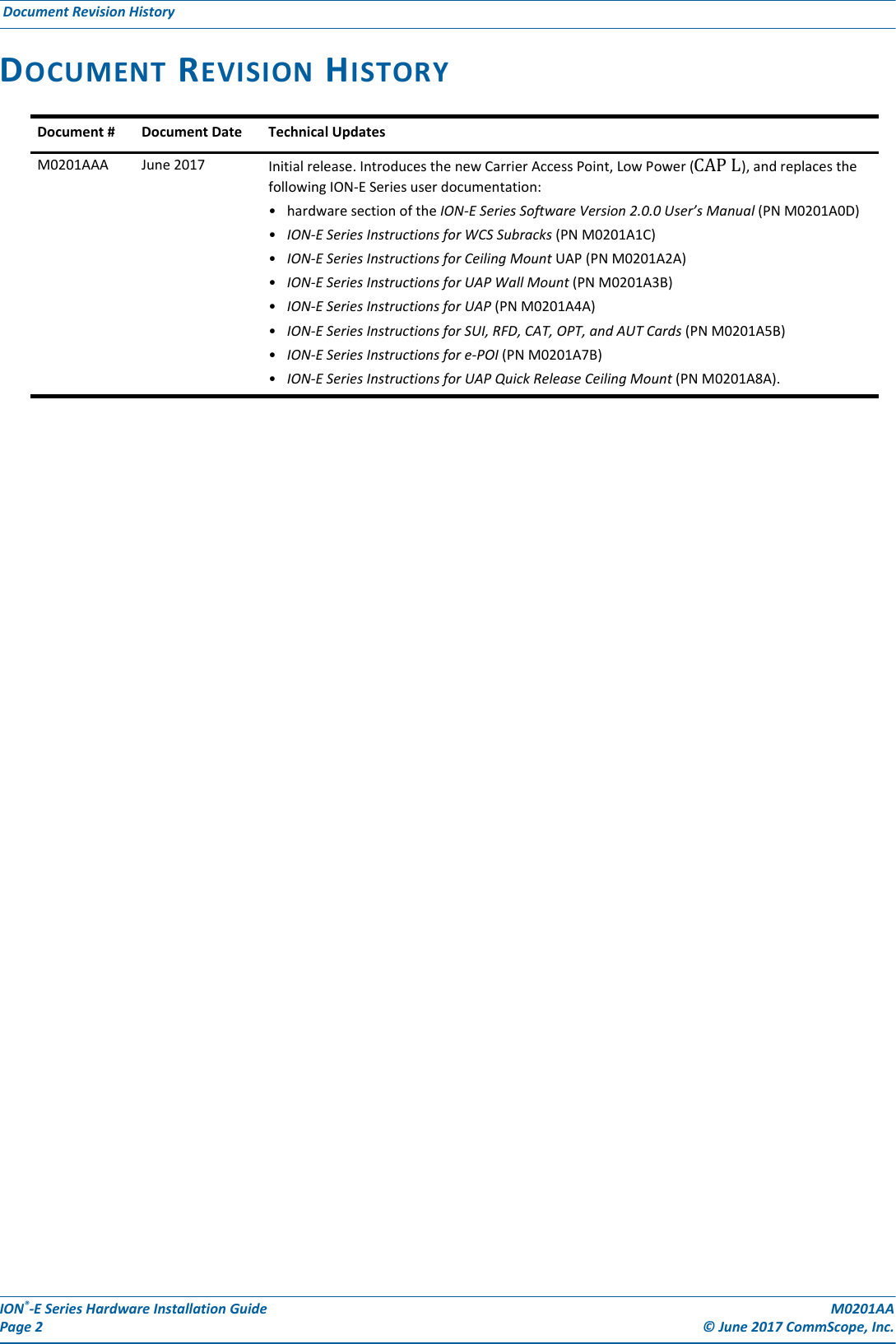

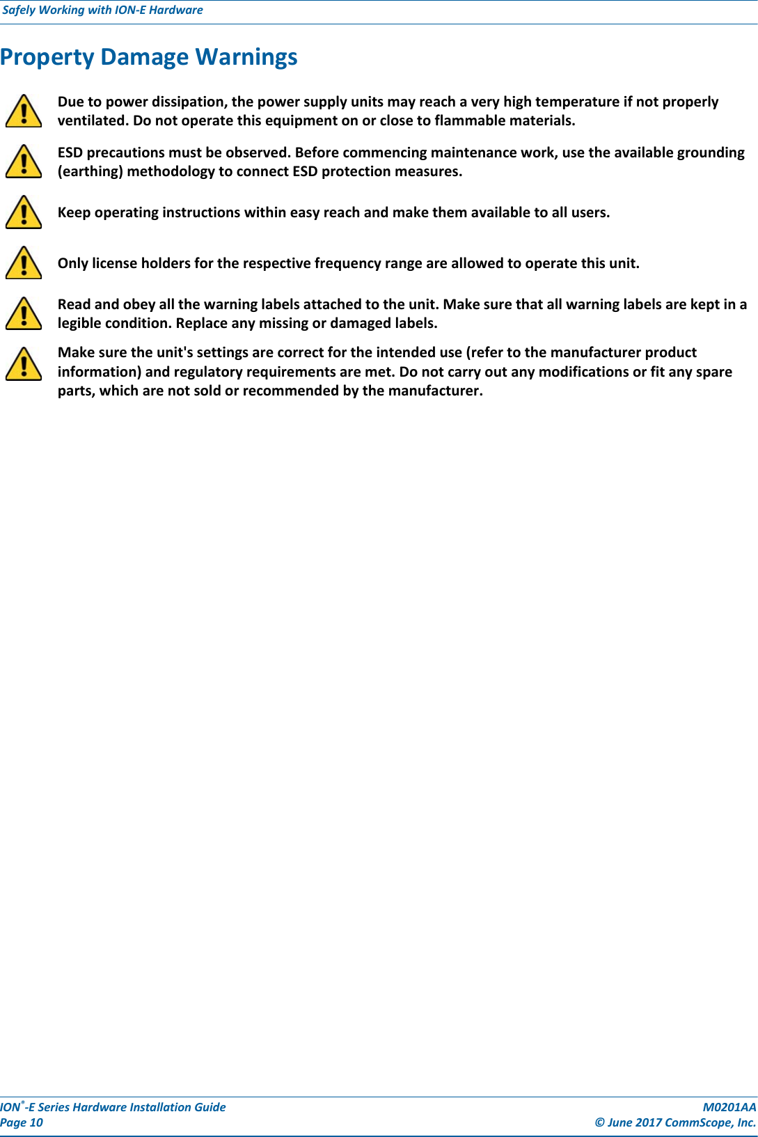
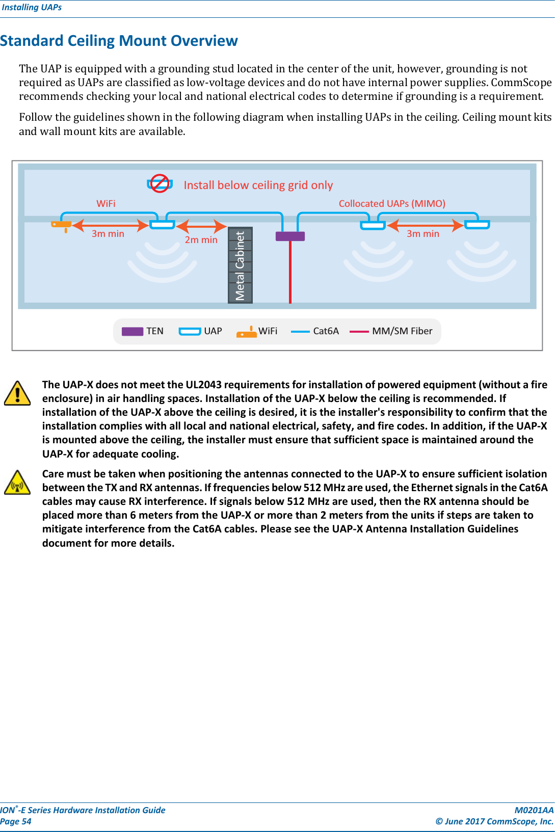
![M0201AA ION®-E Series Hardware Installation Guide© June 2017 CommScope, Inc. Page 11Compliance and Standards CertificationCOMPLIANCE AND STANDARDS CERTIFICATIONFCC RF Exposure RequirementsForinstallations,whichhavetocomplywithFCCRFexposurerequirements,theantennaselectionandinstallationmustbecompletedinawaytoensurecompliancewiththoseFCCrequirements.DependingontheRFfrequency,ratedoutputpower,antennagain,andthelossbetweentherepeaterandantenna,theminimumdistanceDtobemaintainedbetweentheantennalocationandhumanbeingsiscalculatedaccordingtothisformula:where•P(mW)istheradiatedpowerattheantenna,i.e.themax.ratedrepeateroutputpowerinadditiontotheantennagainminusthelossbetweentherepeaterandtheantenna.•PD(mW/cm²)istheallowedPowerDensitylimitacc.to47CFR1.1310(B)forgeneralpopulation/uncontrolledexposureswhichis–f(MHz)/1500forfrequenciesfrom300MHzto1500MHz–1forfrequenciesfrom1500MHzto100,000MHzRFexposurecompliancemayneedtobeaddressedatthetimeoflicensing,asrequiredbytheresponsibleFCCBureau(s),includingantennaco-locationrequirementsof1.1307(b)(3).EMC Standards•ForinstallationsthathavetocomplywithEuropeanEN50385exposurecompliancerequirements,thefollowingPowerDensitylimits/guidelines(W/m²)accordingtoICNIRParevalid:–2forfrequenciesfrom10MHzto400MHz–f(MHz)/200forfrequenciesfrom400MHzto2GHz–10forfrequenciesfrom2GHzto300GHz•ThisunitcomplieswithEuropeanstandardEN60950.This is class A equipment. This equipment can cause radio interference in domestic areas. In this case the operator can be asked to start preventive action.]/[][][24cmmWmWcm PDPD∗∗=π](https://usermanual.wiki/Andrew-Wireless-System/CAPL17E23.users-manual-part-1/User-Guide-3453080-Page-17.png)
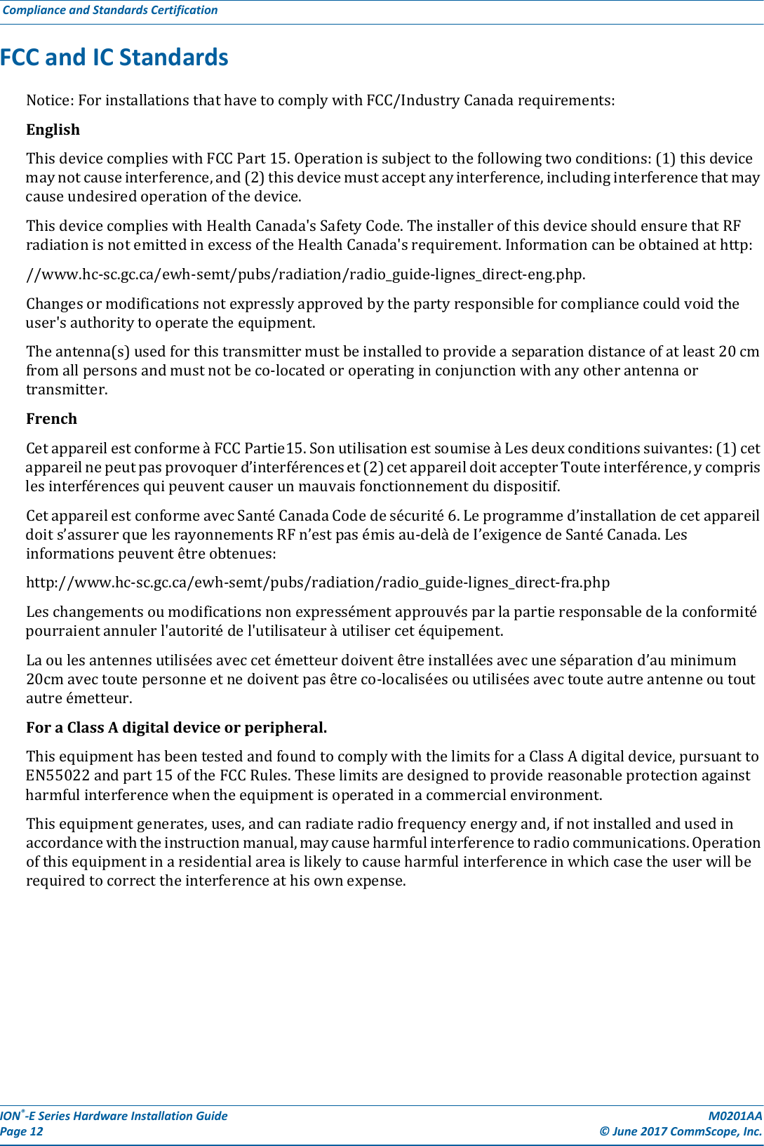
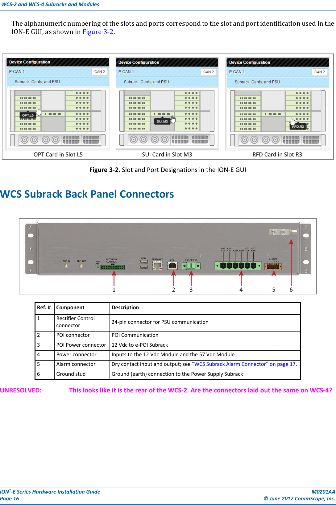
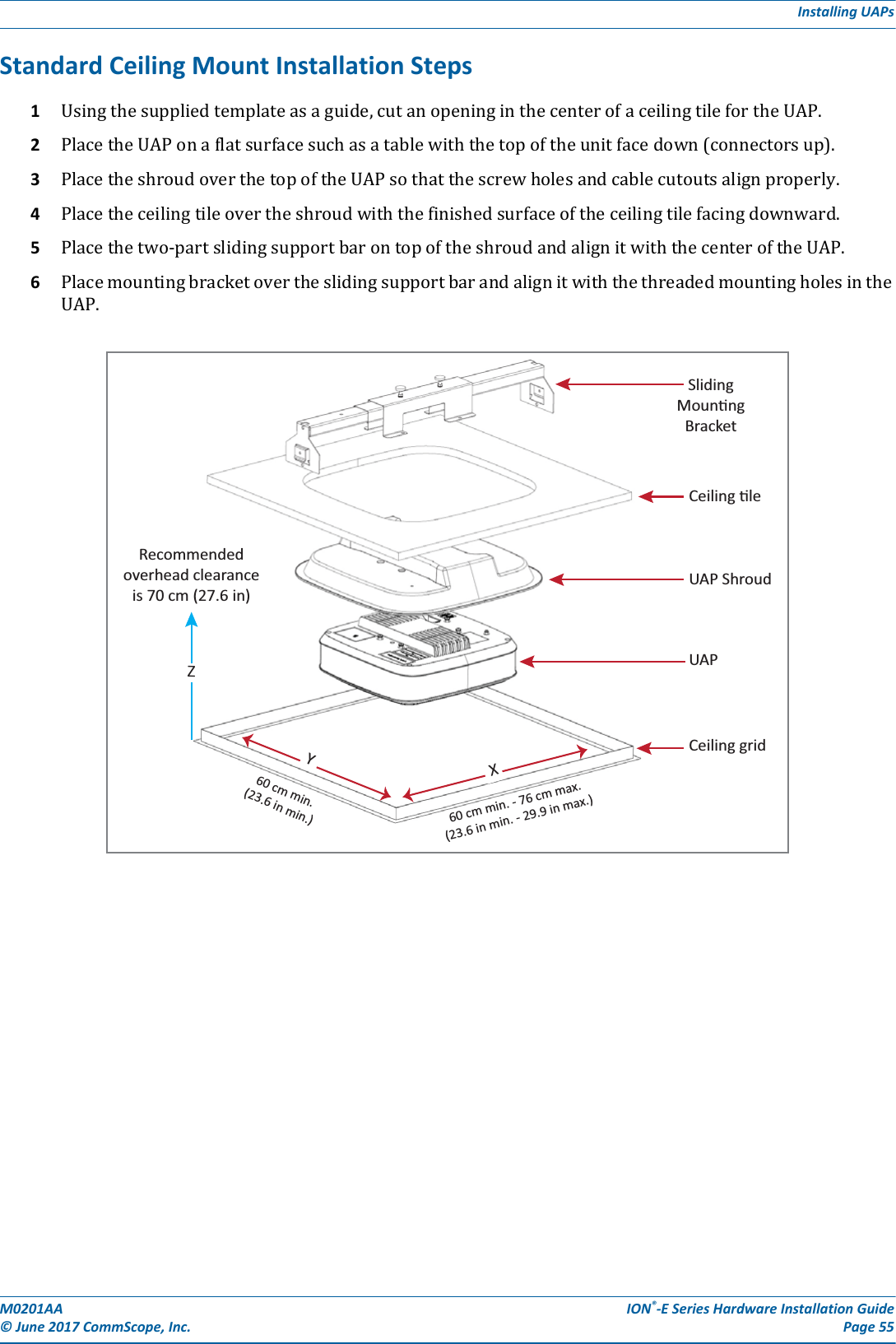
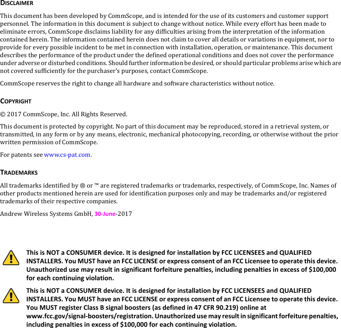
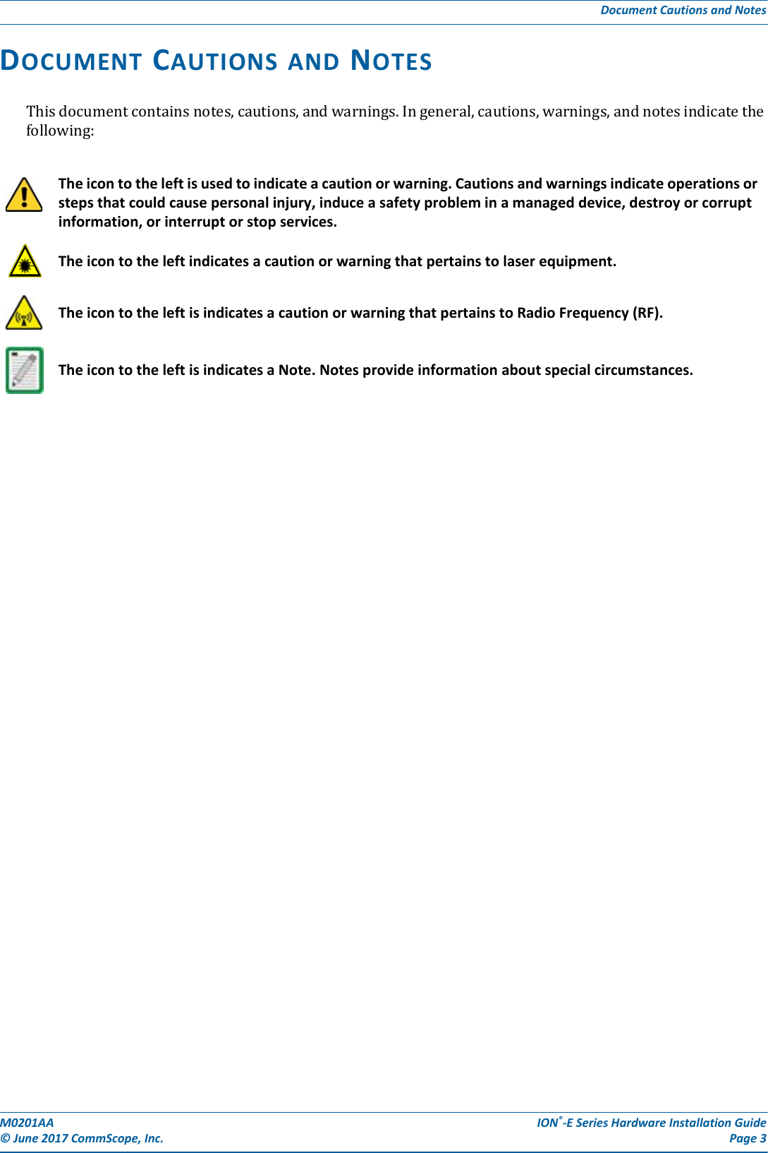
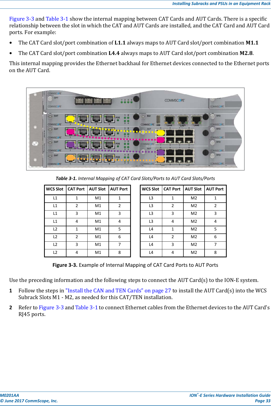
![M0201AA ION®-E Series Hardware Installation Guide© June 2017 CommScope, Inc. Page 17WCS-2 and WCS-4 Subracks and ModulesWCS Subrack Alarm ConnectorTheAlarmconnectoronthebackpaneloftheWCS-4andWCS-2subrackshas•fouropto-isolated(chassis-groundreferenced)drycontactinputstomonitorexternaldevices•oneSummaryAlarmRelaythatenergizeswhenspecificalarmsaretriggered—thethresholdsofwhichareshownintheprecedinggraphic.[Which alarms? We need to match the Summary Alarms shown above with the actual corresponding alarms.]NC COM NOALARMS12345 6 Relay COMGNDIN 1 IN 2 IN 3 IN 4 Relay NORelay NCSummary Alarm2 A max30 Vdc max125 Vac max](https://usermanual.wiki/Andrew-Wireless-System/CAPL17E23.users-manual-part-1/User-Guide-3453080-Page-23.png)

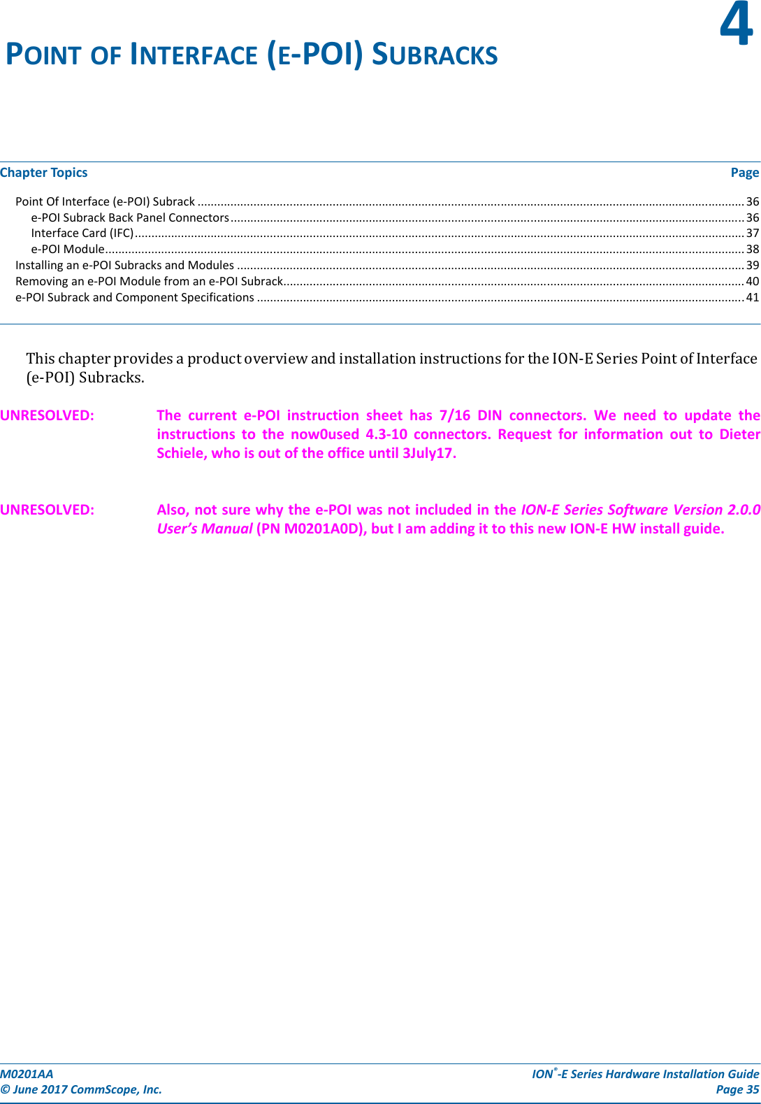
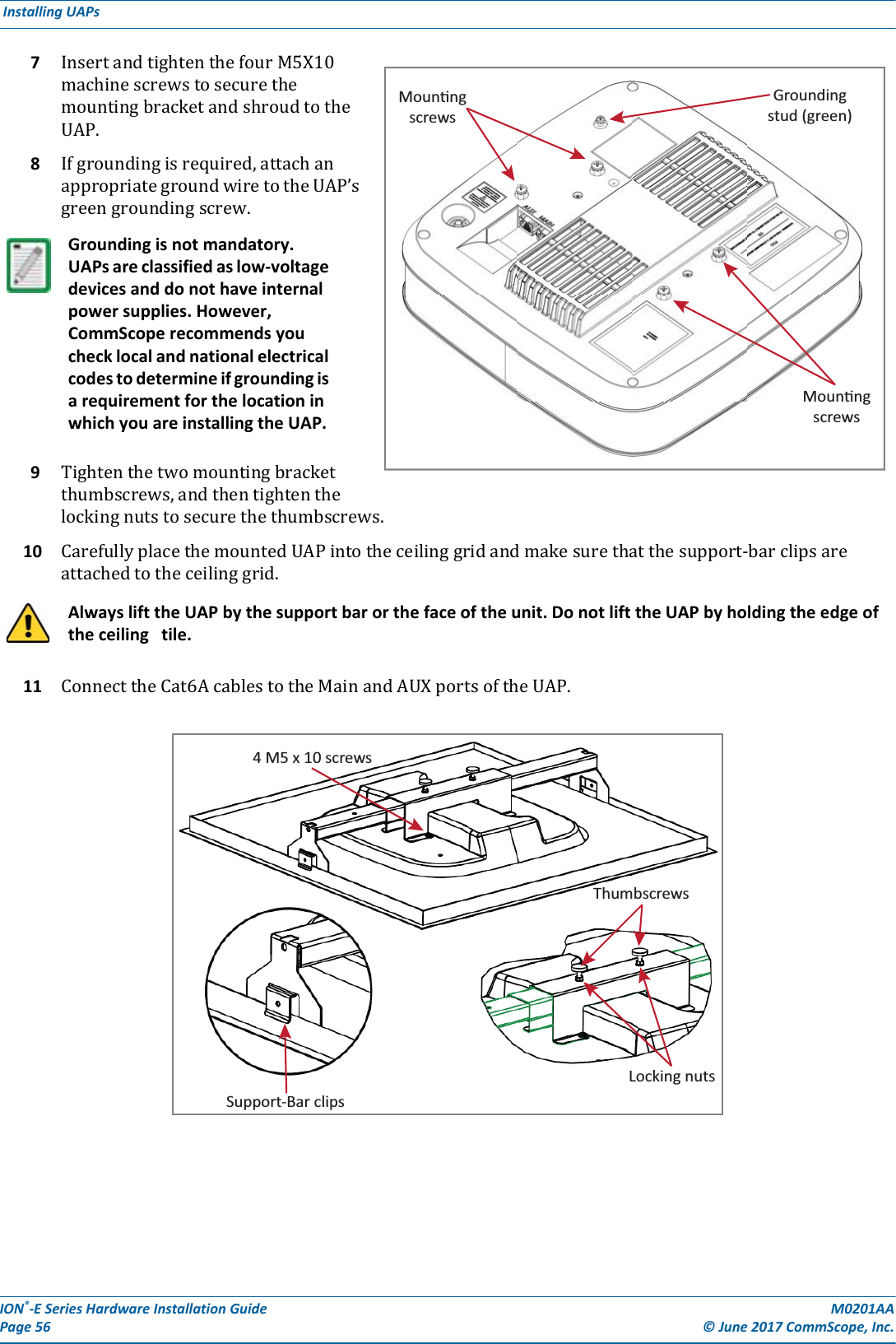
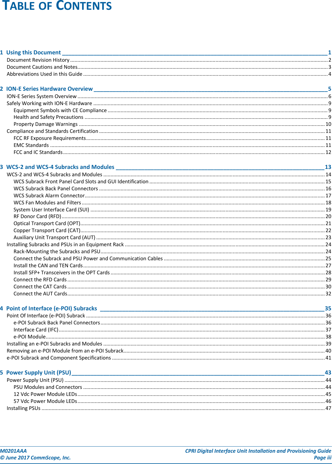
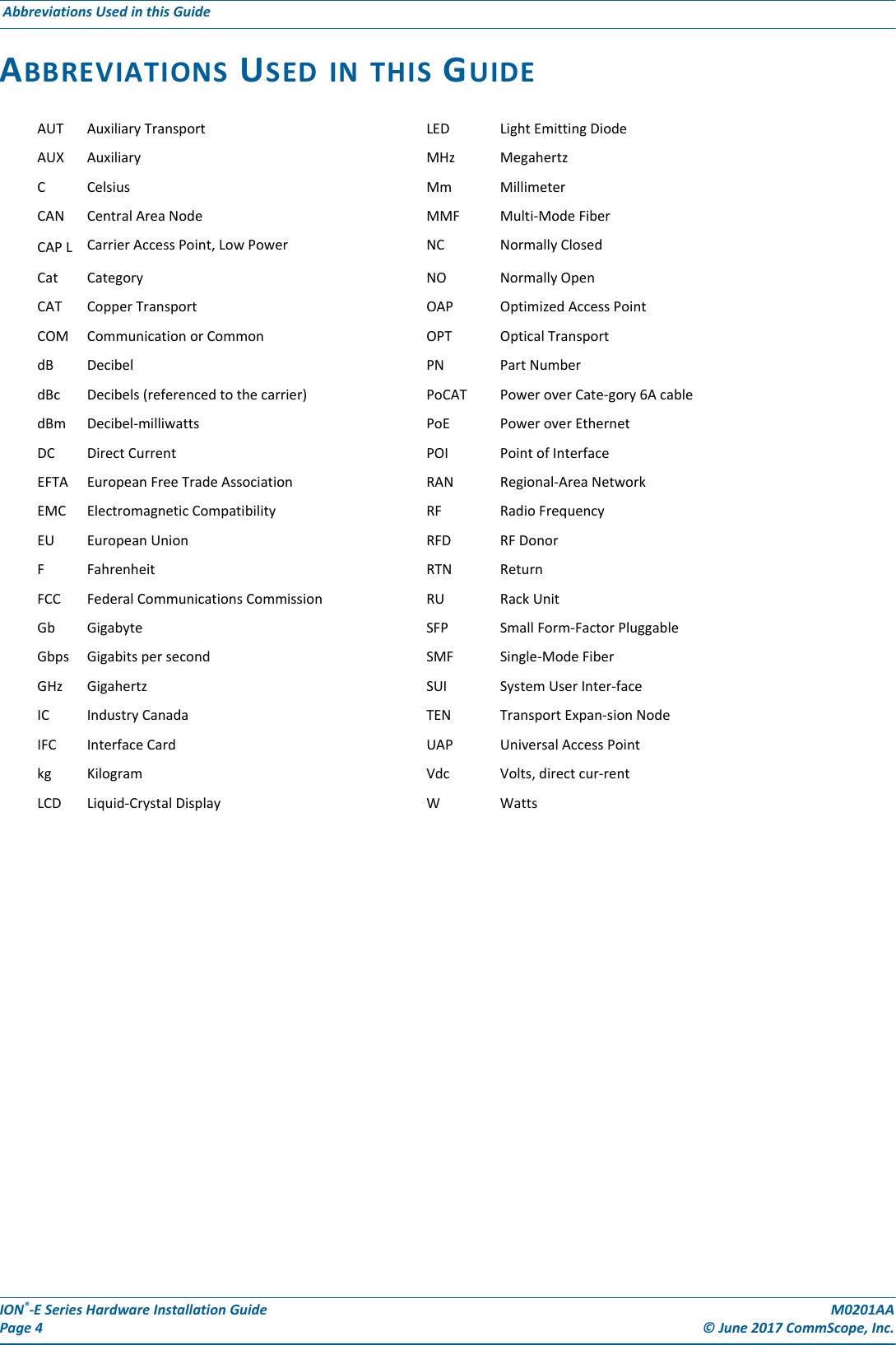
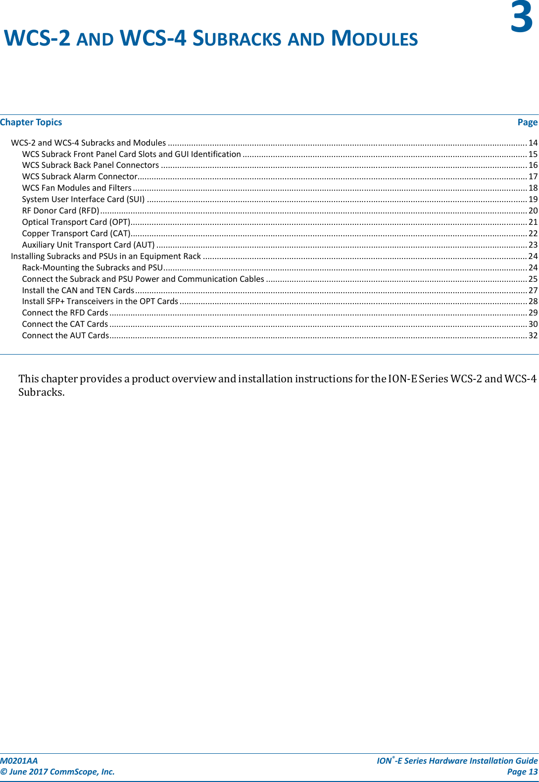
![ION®-E Series Hardware Installation Guide M0201AA Page 36 © June 2017 CommScope, Inc. Point Of Interface (e-POI) Subrack POINT OF INTERFACE (E-POI) SUBRACK TheuniversalION-EPointOfInterface(e-POI)Subrackprovidespower,housing,andcommunicationsforuptoeighte-POIRFDonor(RFD)Cards.[what does the “e” in e-POI mean?]e-POI Subrack Back Panel ConnectorsInterface Car(IFC)e-Poi Subrack supports up to 8 RFD CardsGround studsCommunicaon ports(to WCS Subrack)12 Vdc Input connector(from WCS Subrack)15A Blade Fuse](https://usermanual.wiki/Andrew-Wireless-System/CAPL17E23.users-manual-part-1/User-Guide-3453080-Page-42.png)