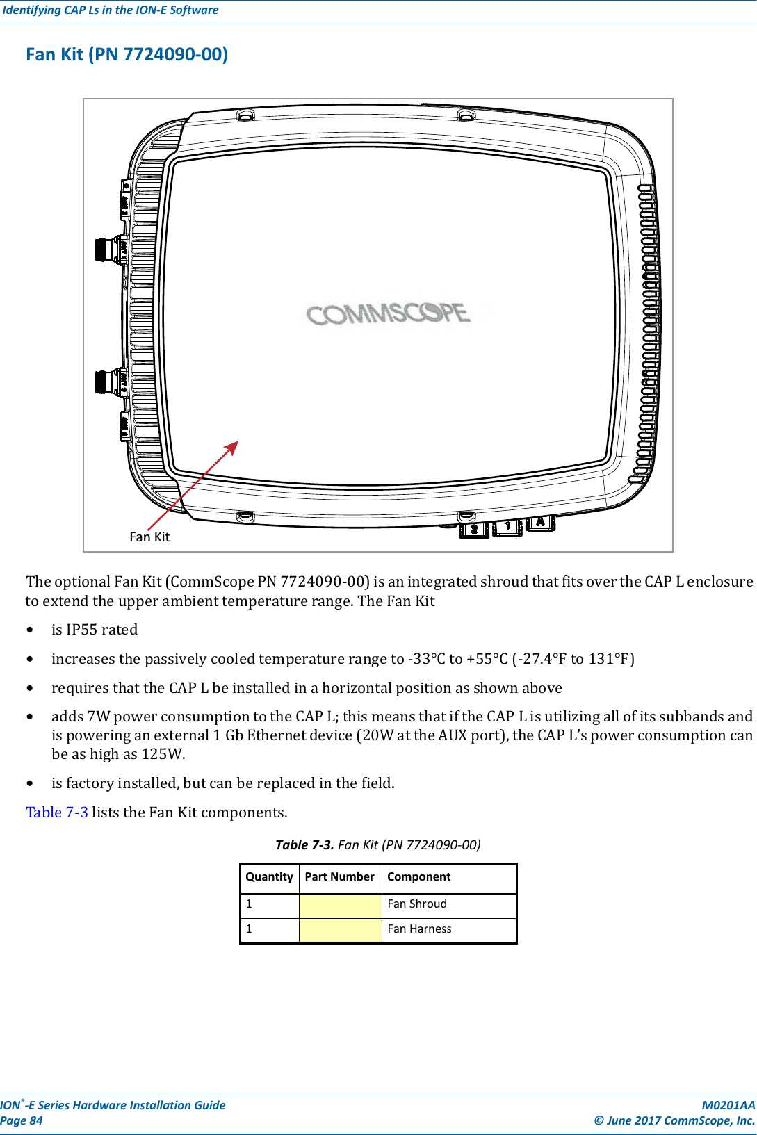
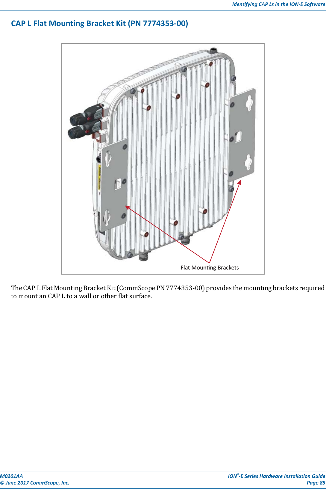
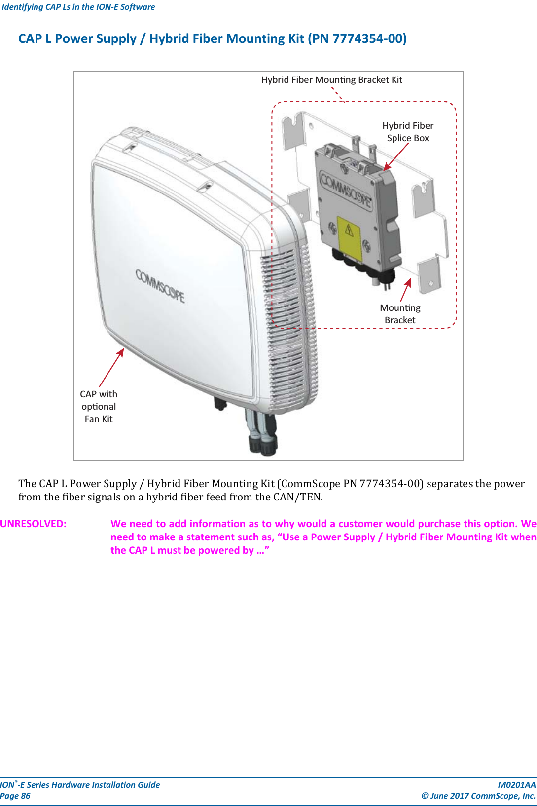
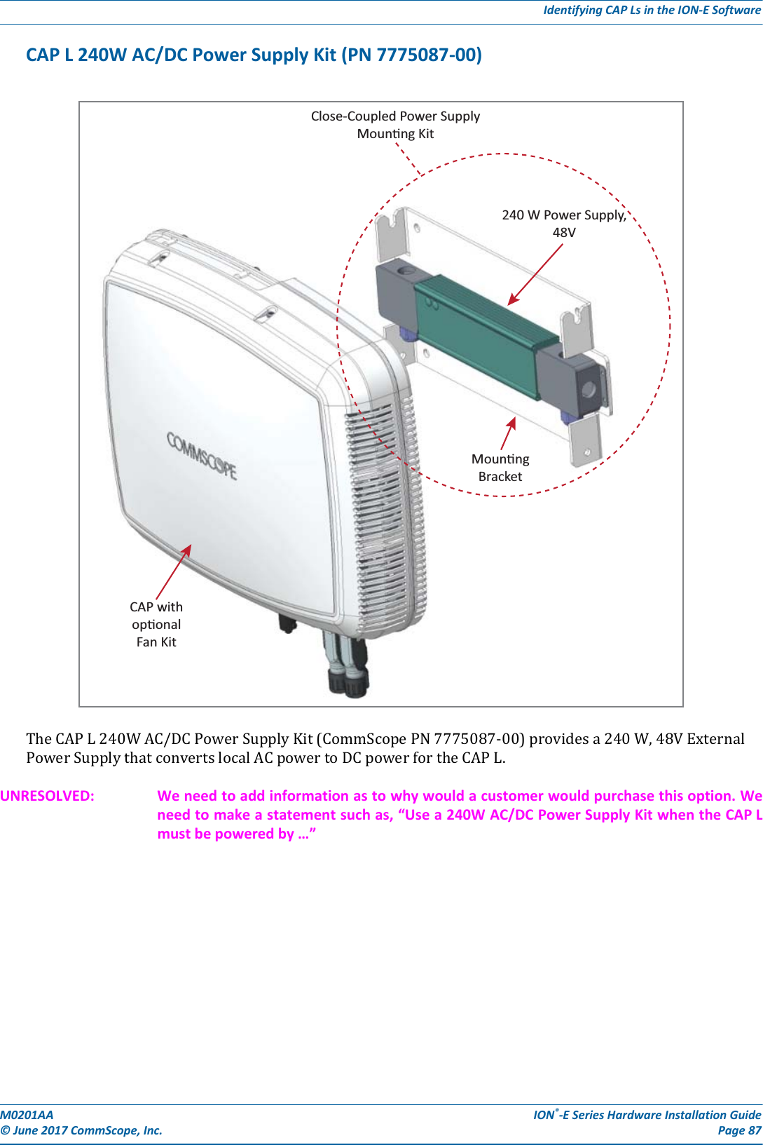
Andrew Wireless System CAPL17E23 ION-E Remote Unit for cellular systems User Manual M0201AAA
Andrew Wireless System ION-E Remote Unit for cellular systems M0201AAA
Contents
- 1. users manual part 1
- 2. users manual part 2
- 3. users manual part 3
- 4. installation manual
users manual part 2
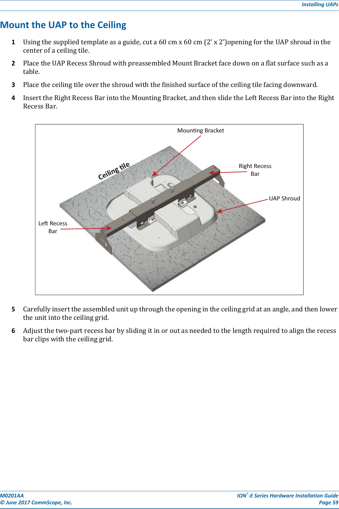
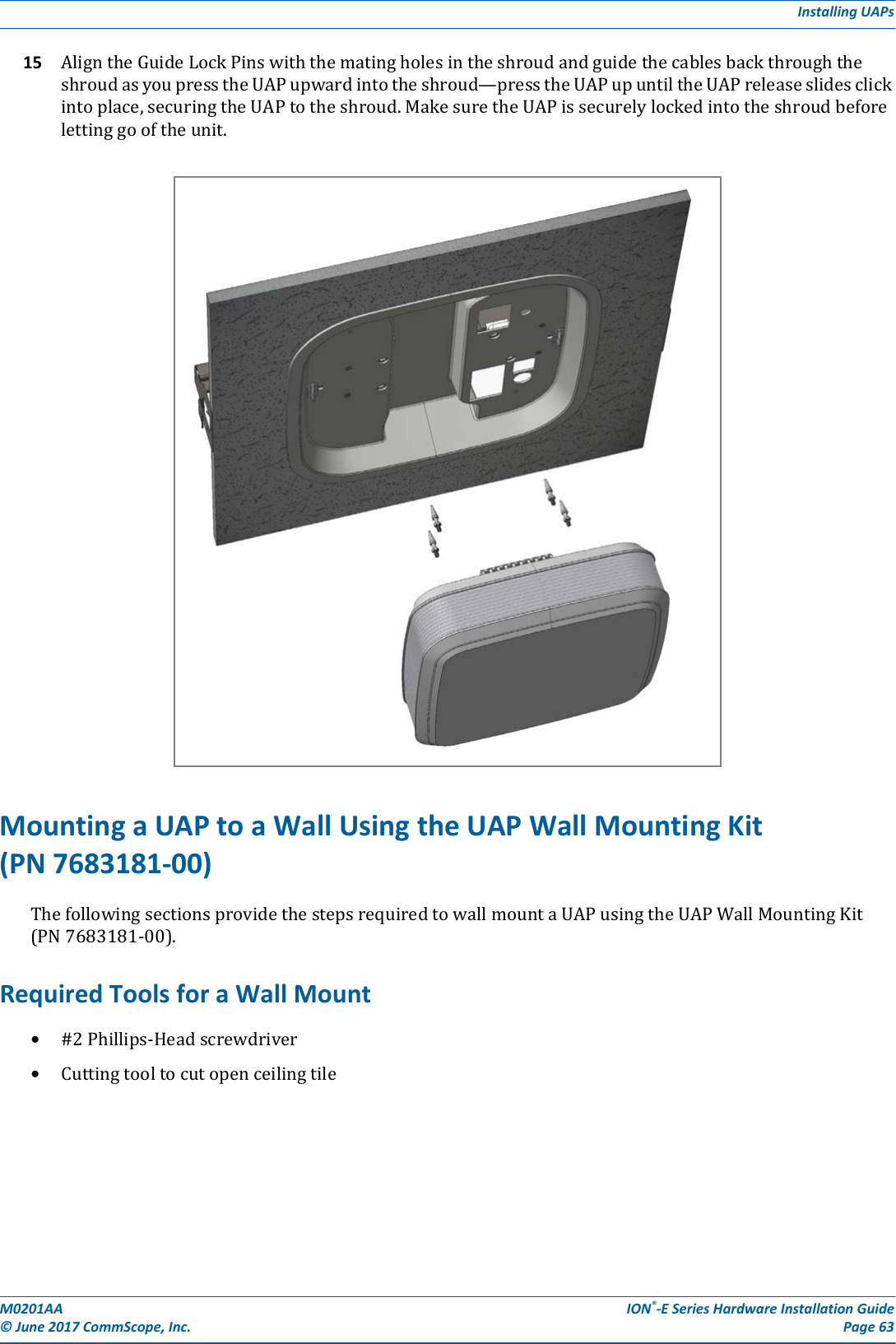
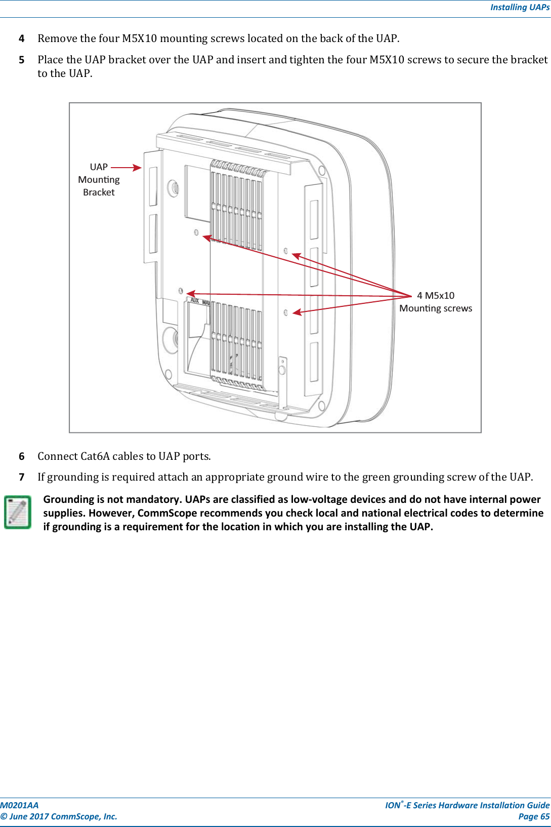
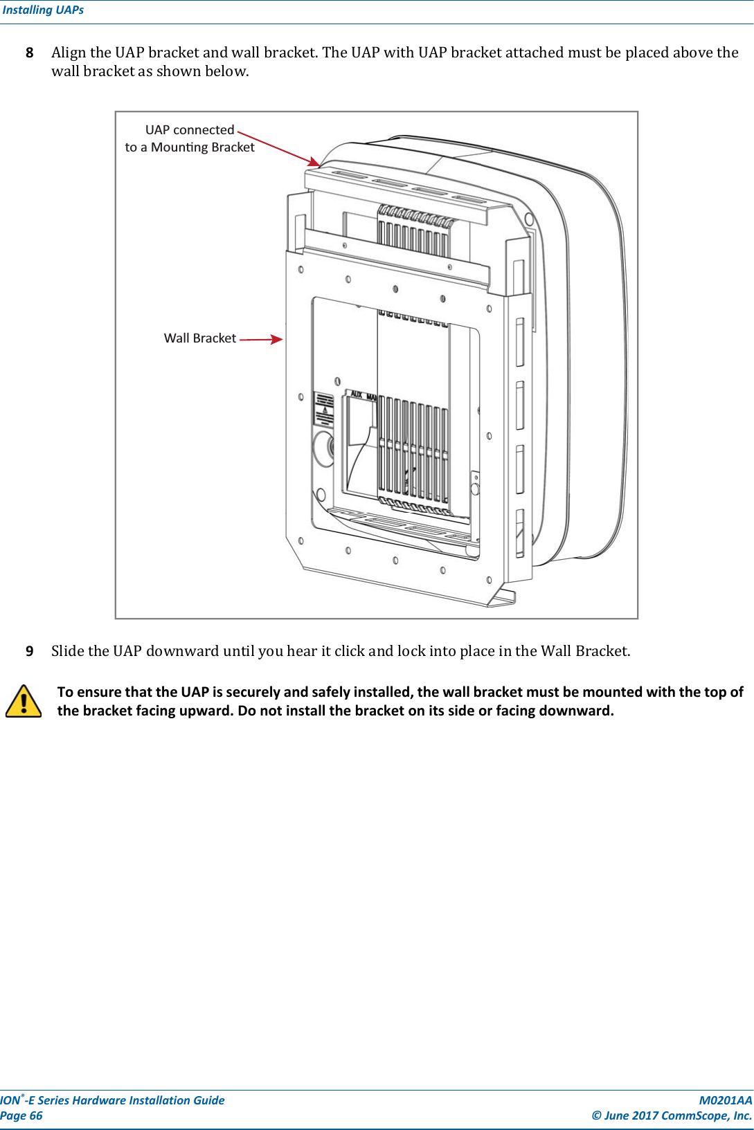
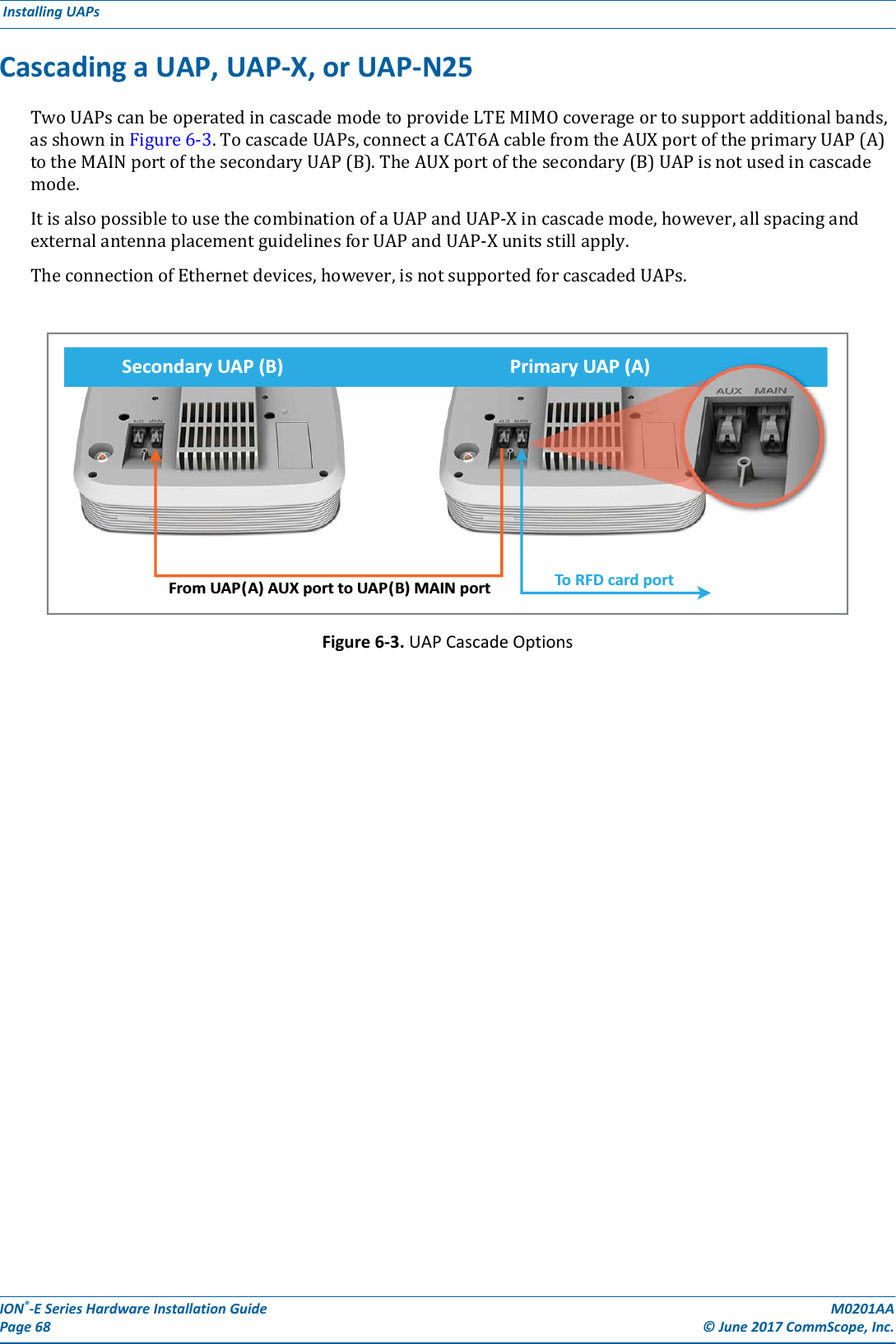
![ION®-E Series Hardware Installation Guide M0201AA Page 64 © June 2017 CommScope, Inc. Installing UAPs Unpack and Inspect the Wall Mounting Kit1Inspecttheexterioroftheshippingcontainer(s)forevidenceofroughhandlingthatmayhavedamagedthecomponentsinthecontainer.2Unpackeachcontainerwhilecarefullycheckingthecontentsfordamageandverifywiththepackingslip.3Ifdamageisfoundorpartsaremissing,fileaclaimwiththecommercialcarrierandnotifyCommScopeTechnicalSupport(see"ContactingDCCSGlobalTechnicalSupport”onpage126).Savethedamagedcartonsforinspectionbythecarrier.4Saveallshippingcontainersforuseiftheequipmentrequiresshipmentatafuturedate.Mount the UAP to a Wall 1SelectthelocationtomounttheUAP.2MounttheWallBrackettoawallusingappropriatefasteners.[PN for the Wall Bracket?]3ThebracketMUSTbemountedinthecorrectorientationwiththetopofthebracketfacingupward(notonitssideorupsidedown),asshownbelow.Table 6-4. Components of the UAP Wall Mounting Kit (PN ??)Quantity Component Description1Wall BracketThe Wall Bracket must be securely mounted to a wall capable of supporting the weight of the UAP (3.2 Kg).The UAP mustbe mounted with this end up.Top(square edges)Boom(angeld edges)Wall Bracket](https://usermanual.wiki/Andrew-Wireless-System/CAPL17E23.users-manual-part-2/User-Guide-3453089-Page-6.png)
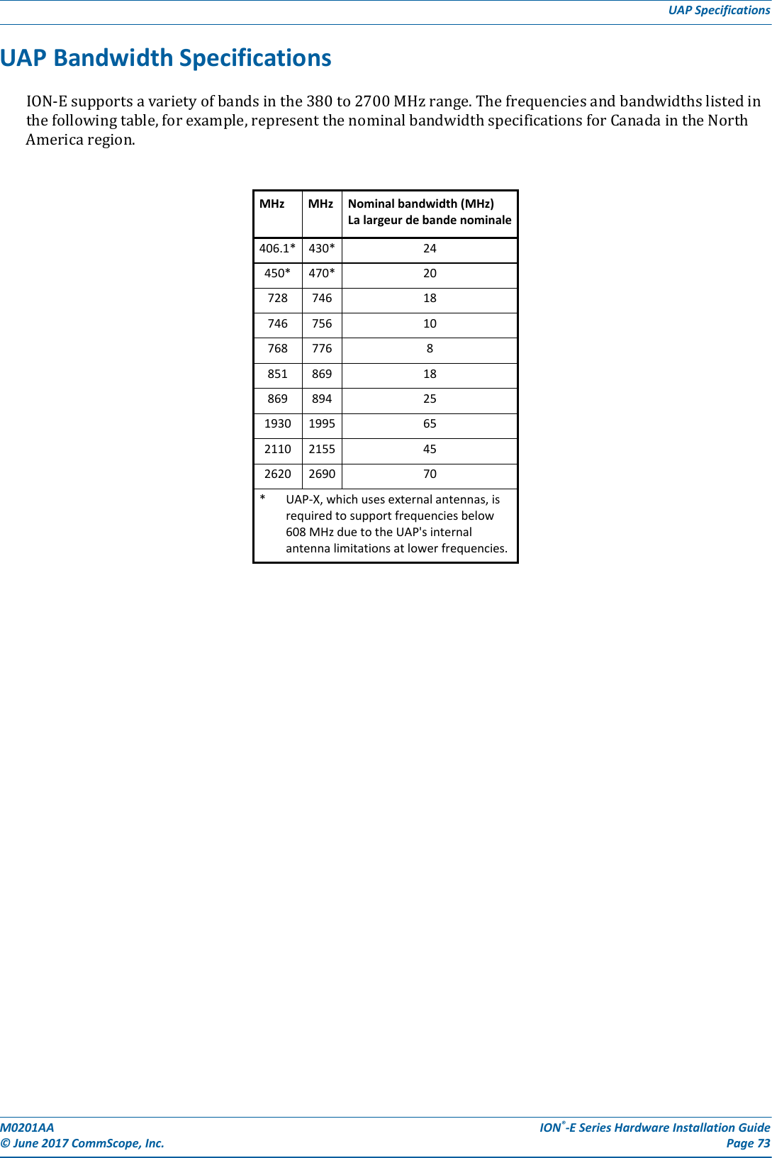

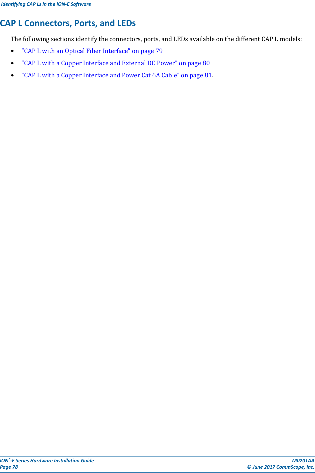
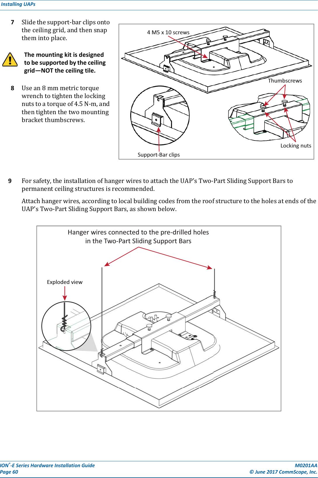
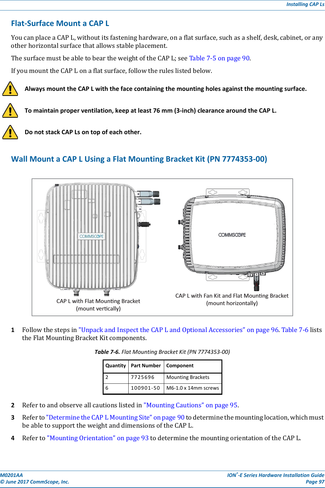
![M0201AA ION®-E Series Hardware Installation Guide© June 2017 CommScope, Inc. Page 79Identifying CAP Ls in the ION-E SoftwareCAP L with an Optical Fiber InterfaceConnectorsREF # Label Description Function1, 4 ANT 3, ANT 4 Not available; connector is plugged.2ANT 1 4.3-10 RF connectorRF connectors that connect to two separate external antennas or to two ports on a cross-polarized dual antenna via 50Ω coaxial cable. Each connector supports two RF bands as described in Table 7-2 on page 77. The end of the 50Ω coaxial cable that connects to an ANT connector can be either a push-pull or a threaded connector. If not used, an ANT connector must be plugged. 3ANT 26 Unlabeled Pushbutton switch Turns power to CAP L on/off. Power to the CAP L may also be shutdown via the ION-E Series Software. [verify can power off via GUI]CAUTION! Prior to disconnecting the Power cable from the CAP L, press the Power button to power off the CAP L. 7 Unlabeled 36 to 60 Vdc Power connectorProprietary 4-pin connector that connects to a local or remote DC power supply, or to a Hybrid Fiber Junction Box. 8 2 Optical Port 2 Optical Port 2 connects to an optional cascaded CAP L unit and provides the main signal interface. Optical transport occurs over Single Mode Fiber (SMF) or Multi Mode Fiber (MMF). This port must be plugged if not in use.9 1 Optical Port 1 Optical Port 1 connects to an ION-E CAN/TEN (possibly through a local Hybrid Fiber Junction Box) and provides the main signal interface. Optical transport occurs over Single Mode Fiber (SMF) or Multi Mode Fiber (MMF); the appropriate SFP+ is factory-installed according to order specifications. 10 A Auxiliary port The AUX port provides a connection for external Ethernet devices such as WiFi and IP cameras. Cabling is via the appropriate CAT cable for the protocol; this model supports an 1000 BASE-T and 802.3at Class 3 Power over Cat6A Ethernet connection. Maximum attached cable length is 3 meters (9.8 feet). The AUX port must be plugged if not in use. Power LED (unlabeled)Ref # LED Color Description5• Blue • CAP L is powered on and operational.• Flashing blue • CAP L is powered on and initializing.• Off • CAP L is not powered on.For further information, see "Powering a CAP L” on page 82.12347891056](https://usermanual.wiki/Andrew-Wireless-System/CAPL17E23.users-manual-part-2/User-Guide-3453089-Page-21.png)
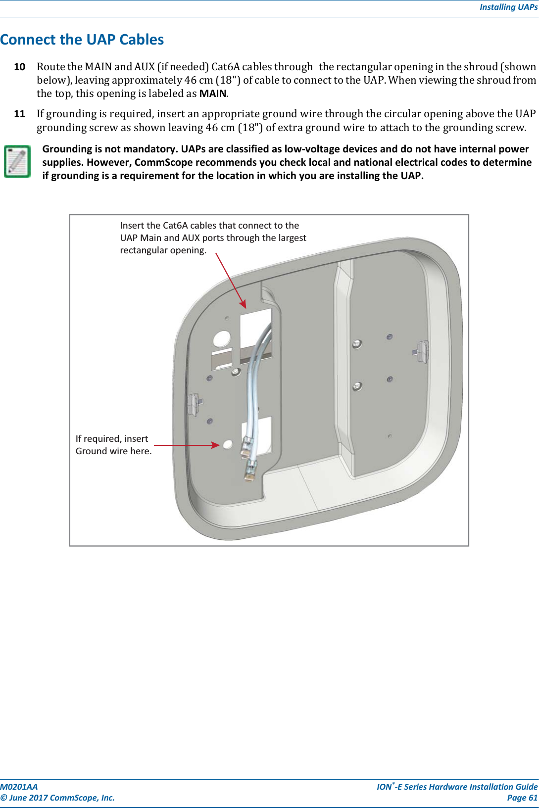
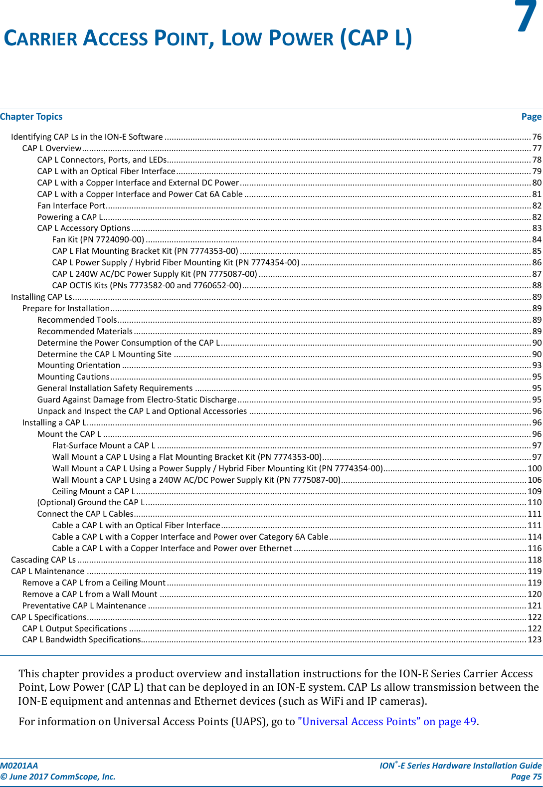
![ION®-E Series Hardware Installation Guide M0201AA Page 80 © June 2017 CommScope, Inc. Identifying CAP Ls in the ION-E Software CAP L with a Copper Interface and External DC PowerConnectorsREF # Label Description Function1, 4 ANT 3, ANT 4 Not available; connector is plugged.2ANT 1 4.3-10 RF connectorRF connectors that connect to two separate external antennas or to two ports on a cross-polarized dual antenna via 50Ω coaxial cable. Each connector supports two RF bands as described in Table 7-2 on page 77. The end of the 50Ω coaxial cable that connects to an ANT connector can be either a push-pull or a threaded connector. If not used, an ANT connector must be plugged. 3ANT 26 Unlabeled Pushbutton switch Turns power to CAP L on/off. Power to the CAP L may also be shutdown via the ION-E Series Software. [verify can power off via GUI]CAUTION! Prior to disconnecting the Power cable from the CAP L, press the Power button to power off the CAP L. 7 Unlabeled 36 to 60 Vdc Power connector Connects to local or remote power.8 2 Port 2 Plugged, not applicable to this model configuration.9 1 Port 1 Port 1 connects to an ION-E CAN/TEN via CAT 6A cable and provides the main signal interface. 10 A RJ-45 connector The AUX port provides a cascade connection to an optional locally powered cascaded CAP L, or provides a connection to external Ethernet devices such as WiFi and IP cameras. Cabling is via the appropriate CAT cable for the protocol; this model supports an 1000 BASE-T and 802.3at Class 3 Power over Cat6A Ethernet connection. Maximum attached cable length is 3 meters (9.8 feet). The AUX port must be plugged if not in use. Power LED (unlabeled)Ref # LED Color Description5• Blue • CAP L is powered on and operational.• Flashing blue • CAP L is powered on and initializing.• Off • CAP L is not powered on.For further information, see "Powering a CAP L” on page 82.12347891056](https://usermanual.wiki/Andrew-Wireless-System/CAPL17E23.users-manual-part-2/User-Guide-3453089-Page-22.png)
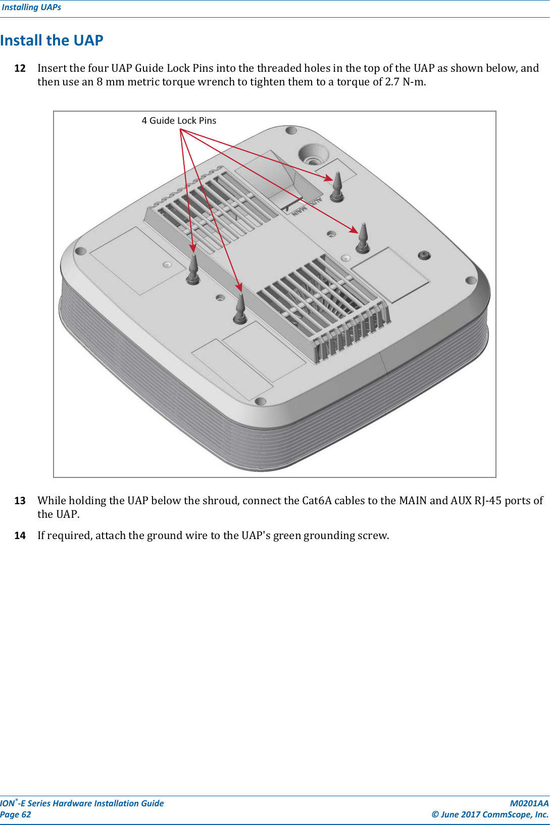
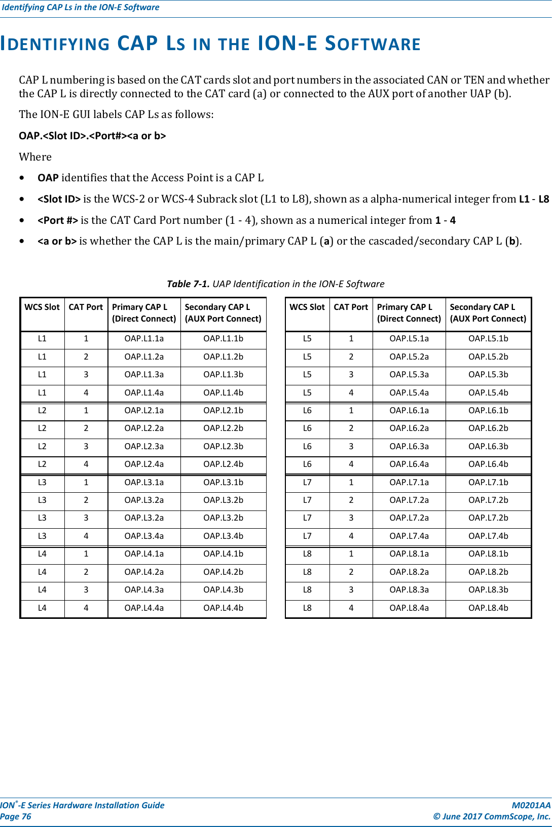
![M0201AA ION®-E Series Hardware Installation Guide© June 2017 CommScope, Inc. Page 81Identifying CAP Ls in the ION-E SoftwareCAP L with a Copper Interface and Power Cat 6A CableConnectorsREF # Label Description Function1, 4 ANT 3, ANT 4 Not available; connector is plugged.2ANT 1 4.3-10 RF connectorRF connectors that connect to two separate external antennas or to two ports on a cross-polarized dual antenna via 50Ω coaxial cable. Each connector supports two RF bands as described in Table 7-2 on page 77. The end of the 50Ω coaxial cable that connects to an ANT connector can be either a push-pull or a threaded connector. If not used, an ANT connector must be plugged. 3ANT 26 Unlabeled Pushbutton switch Turns power to CAP L on/off. Power to the CAP L may also be shutdown via the ION-E Series Software. [verify can power off via GUI]CAUTION! Prior to disconnecting the Power cable from the CAP L, press the Power button to power off the CAP L. 7 Unlabeled 36 to 60 Vdc Power connector Plugged, not applicable to this model configuration.8 2 Port 2 Plugged, not applicable to this model configuration.9 1 Port 1 Port 1 connects to an ION-E CAN/TEN via CAT 6A cable and provides the main signal and power interface. 10 A RJ-45 connector The AUX port provides a cascade connection to an optional locally powered secondary CAP L, or provides a connection to external Ethernet devices such as WiFi and IP cameras. Cabling is via the appropriate CAT cable for the protocol; this model supports an 1000 BASE-T and 802.3at Class 3 Power over Cat6A Ethernet connection. Maximum attached cable length is 3 meters (9.8 feet). The AUX port must be plugged if not in use. Power LED (unlabeled)Ref # LED Color Description5• Blue • CAP L is powered on and operational.• Flashing blue • CAP L is powered on and initializing.• Off • CAP L is not powered on.For further information, see "Powering a CAP L” on page 82.12347891056](https://usermanual.wiki/Andrew-Wireless-System/CAPL17E23.users-manual-part-2/User-Guide-3453089-Page-23.png)
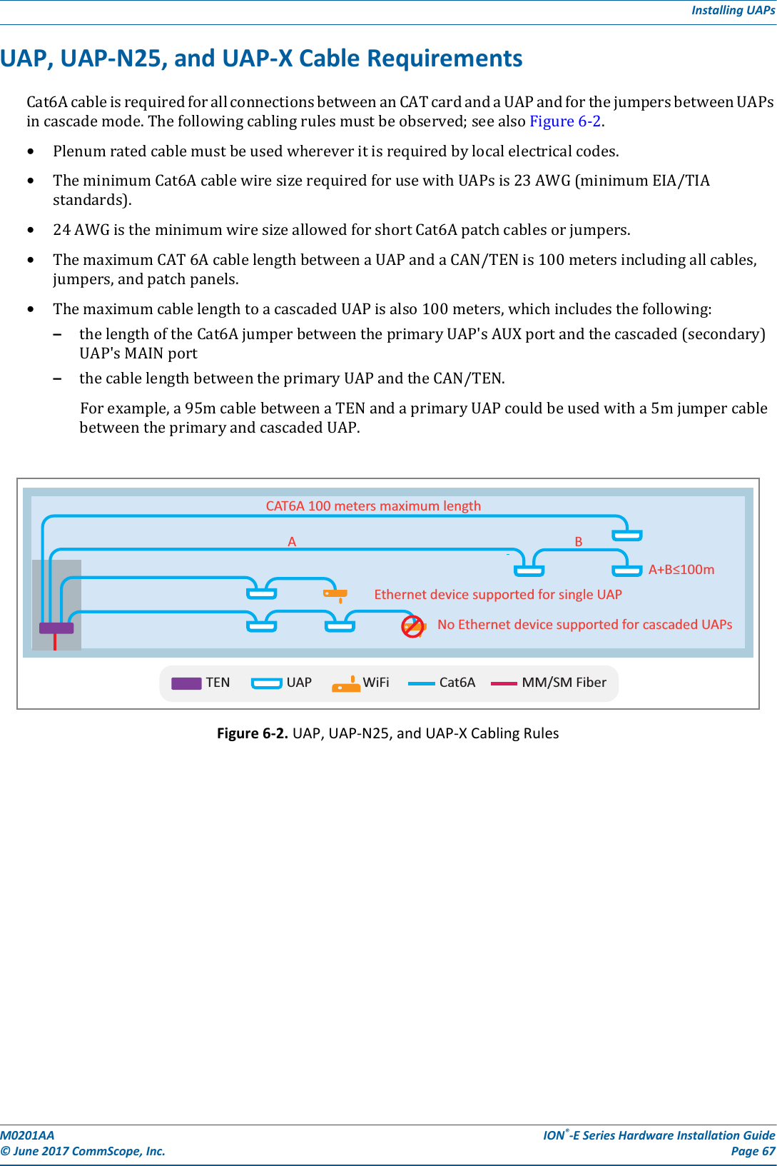
![M0201AA ION®-E Series Hardware Installation Guide© June 2017 CommScope, Inc. Page 89Installing CAP LsINSTALLING CAP LSPrepare for InstallationDothefollowingbeforebeginninginstallation.•Reviewandknowthecautionsin"GeneralInstallationSafetyRequirements”onpage95.•Reviewthesystemdesignplan.•Identifytheequipmentinstallationsite.•Reviewthepowerrequirementstomakesurethesitecansupportthisinstallation.•Mapoutallcableruns.•Identifyandobtainalltoolsandmaterialsrequiredtocompletetheinstallation.Recommended Tools•ElectrostaticDischarge(ESD)wriststrap•#2Phillipsscrewdriver•DrillandbitstomountCAPLtoawallorceiling[not sure what tools are needed]•FibercleaningequipmentRecommended Materials•#18AWG(1.0mm)insulatedstrandedcopperwireforchassisground[I used a standard gauge, not sure if we recommend this or another gauge]•some type of screw to attach mounting brackets to wall/ceilingThis section describes how to install a CAP L; for information on how to install a UAP, UAP-N25, or UAP-X, go to "Installing UAPs” on page 53.](https://usermanual.wiki/Andrew-Wireless-System/CAPL17E23.users-manual-part-2/User-Guide-3453089-Page-31.png)
![M0201AA ION®-E Series Hardware Installation Guide© June 2017 CommScope, Inc. Page 91Installing CAP LsFigure 7-1. Mounting Dimensions for a CAP L Mounted with the Flat Mounting Bracket KitFigure 7-2. Mounting Dimensions for a CAP L Mounted with the Power Supply / Hybrid Fiber Mounting Kit489.12mm[19.26”]448mm[17.64”]144mm[5.67”]440mm[17.32”]120[4.72]383.34[15.09]512[20.16]30 2X[1.18]424.53[16.71]390.33[15.37]24[0.94]2X188[7.4] 460.75[18.14]](https://usermanual.wiki/Andrew-Wireless-System/CAPL17E23.users-manual-part-2/User-Guide-3453089-Page-33.png)
![ION®-E Series Hardware Installation Guide M0201AA Page 92 © June 2017 CommScope, Inc. Installing CAP Ls Figure 7-3. Mounting Dimensions for a CAP L Mounted with the 240W AC/DC Power Supply Kit120[4.72]31.5[1.24]30 2X[1.18]24[0.94]2X104.73[4.12]158.42[6.24]468.12[18.43]432.45[17.03]398.3[15.68]448[17.64]373.89[14.72]87.44[3.44]188[7.4]398[15.669]](https://usermanual.wiki/Andrew-Wireless-System/CAPL17E23.users-manual-part-2/User-Guide-3453089-Page-34.png)
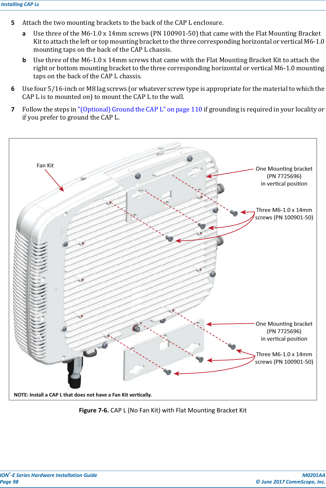
![ION®-E Series Hardware Installation Guide M0201AA Page 104 © June 2017 CommScope, Inc. Installing CAP Ls 5AttachtheHybridFiberSpliceBox(PN7693816-00)totheWallMountingBracket(PN7771350).[Use what screws? None were shown in the assembly drawings. Or does it clip to the bracket?]6UsethesixM6-1.0x14mmscrews(PN100901-50)toattachthetwoAngledMountingBrackets(PN7771351)tothebackoftheCAPLchassis.RefertooneofthefollowingfiguresforthelocationofthecorrespondingsixM6-1.0mountingtaps:•CAPL,noFanKit—Figure7-8•CAPLwithFanKit—Figure7-9onpage105.7UsethefourM8x16flange-headscrews(PN100762-1)toattachtheassembledHybridFiberSpliceBoxandWallMountingBrackettotheAngledMountingBracketsthatyouattachedtotheCAPLinStep6.Figure 7-8. CAP L (No Fan Kit) with Power Supply / Hybrid Fiber Mounting KitSix M6-1.0 x 14mm screwsOne HybridFiber Splice BoxOne Wall Mounng BracketTwo AngledMounng BracketsFour M8x16 flange-head screwsNOTE: Install a CAP L that does nothave a Fan Kit vercally.](https://usermanual.wiki/Andrew-Wireless-System/CAPL17E23.users-manual-part-2/User-Guide-3453089-Page-46.png)