Andrew Wireless System CAPL17E23 ION-E Remote Unit for cellular systems User Manual M0201AAA
Andrew Wireless System ION-E Remote Unit for cellular systems M0201AAA
Contents
- 1. users manual part 1
- 2. users manual part 2
- 3. users manual part 3
- 4. installation manual
users manual part 2
M0201AA ION®-E Series Hardware Installation Guide
© June 2017 CommScope, Inc. Page 59
Installing UAPs
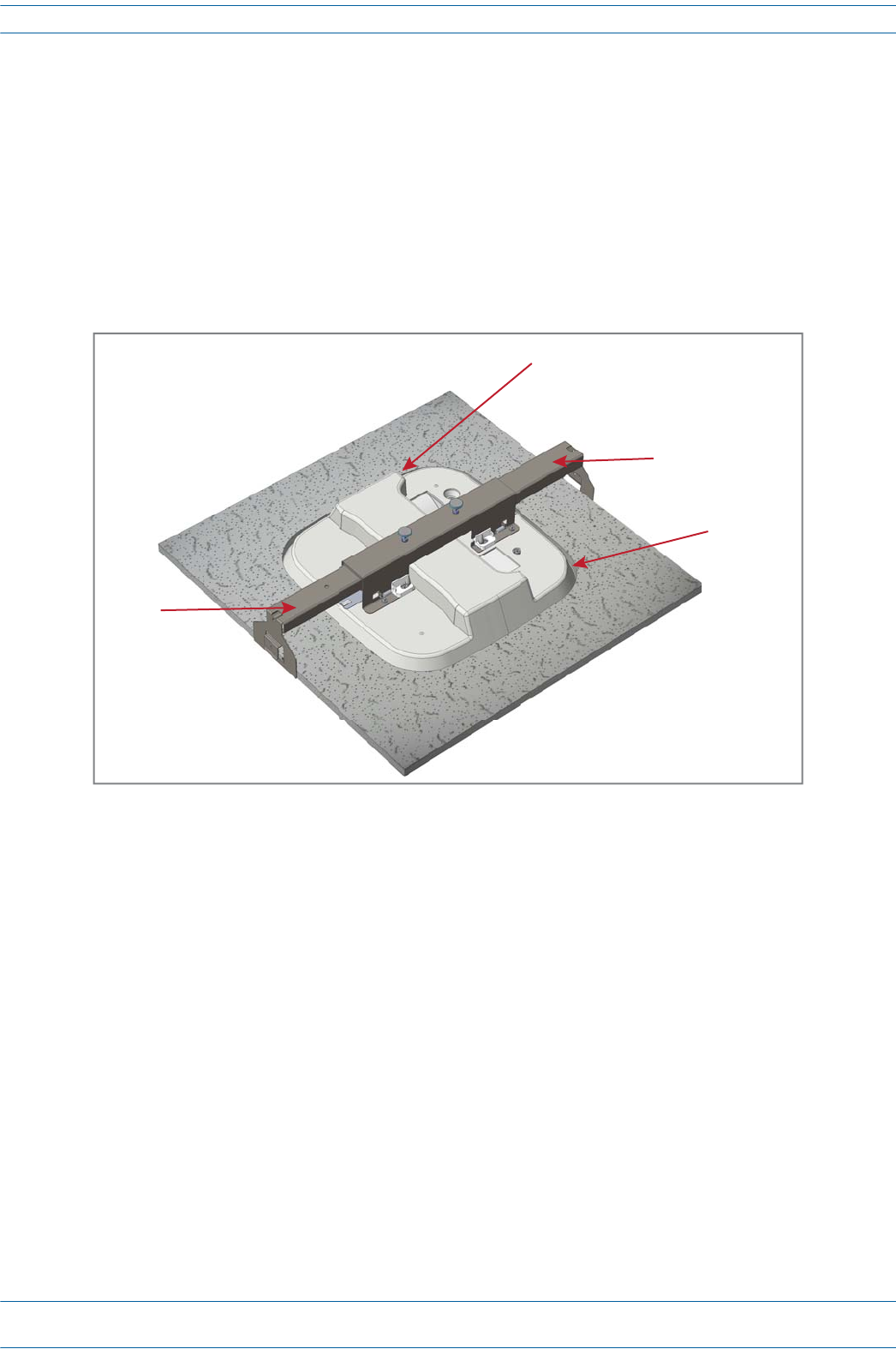
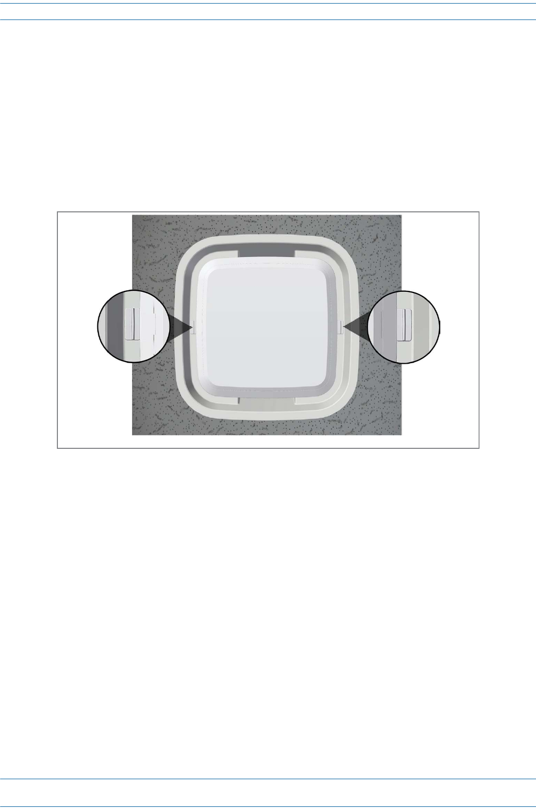
Mount the UAP to the Ceiling
1Usingthesuppliedtemplateasaguide,cuta60cmx60cm(2'x2')openingfortheUAPshroudinthe
centerofaceilingtile.
2PlacetheUAPRecessShroudwithpreassembledMountBracketfacedownonaflatsurfacesuchasa
table.
3Placetheceilingtileovertheshroudwiththefinishedsurfaceoftheceilingtilefacingdownward.
4InserttheRightRecessBarintotheMountingBracket,andthenslidetheLeftRecessBarintotheRight
RecessBar.
5Carefullyinserttheassembledunitupthroughtheopeningintheceilinggridatanangle,andthenlower
theunitintotheceilinggrid.
6Adjustthetwo-partrecessbarbyslidingitinoroutasneededtothelengthrequiredtoaligntherecess
barclipswiththeceilinggrid.
Ceiling le
Right Recess
Bar
Le Recess
Bar
Mounng Bracket
UAP Shroud
ION®-E Series Hardware Installation Guide M0201AA
Page 60 © June 2017 CommScope, Inc.
Installing UAPs
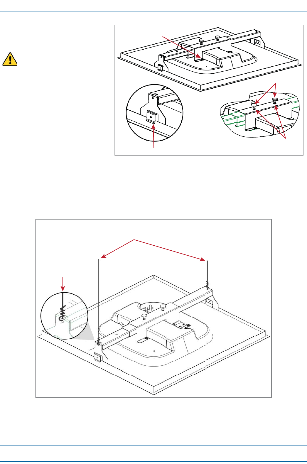
7Slidethesupport-barclipsonto
theceilinggrid,andthensnap
themintoplace.
8Usean8mmmetrictorque
wrenchtotightenthelocking
nutstoatorqueof4.5N-m,and
thentightenthetwomounting
bracketthumbscrews.
9Forsafety,theinstallationofhangerwirestoattachtheUAP'sTwo-PartSlidingSupportBarsto
permanentceilingstructuresisrecommended.
Attachhangerwires,accordingtolocalbuildingcodesfromtheroofstructuretotheholesatendsofthe
UAP'sTwo-PartSlidingSupportBars,asshownbelow.
The mounting kit is designed
to be supported by the ceiling
grid—NOT the ceiling tile.
4 M5 x 10 screws
Support-Bar clips
Thumbscrews
Locking nuts
Hanger wires connected to the pre-drilled holes
in the Two-Part Sliding Support Bars
Exploded view
M0201AA ION®-E Series Hardware Installation Guide
© June 2017 CommScope, Inc. Page 61
Installing UAPs
Connect the UAP Cables
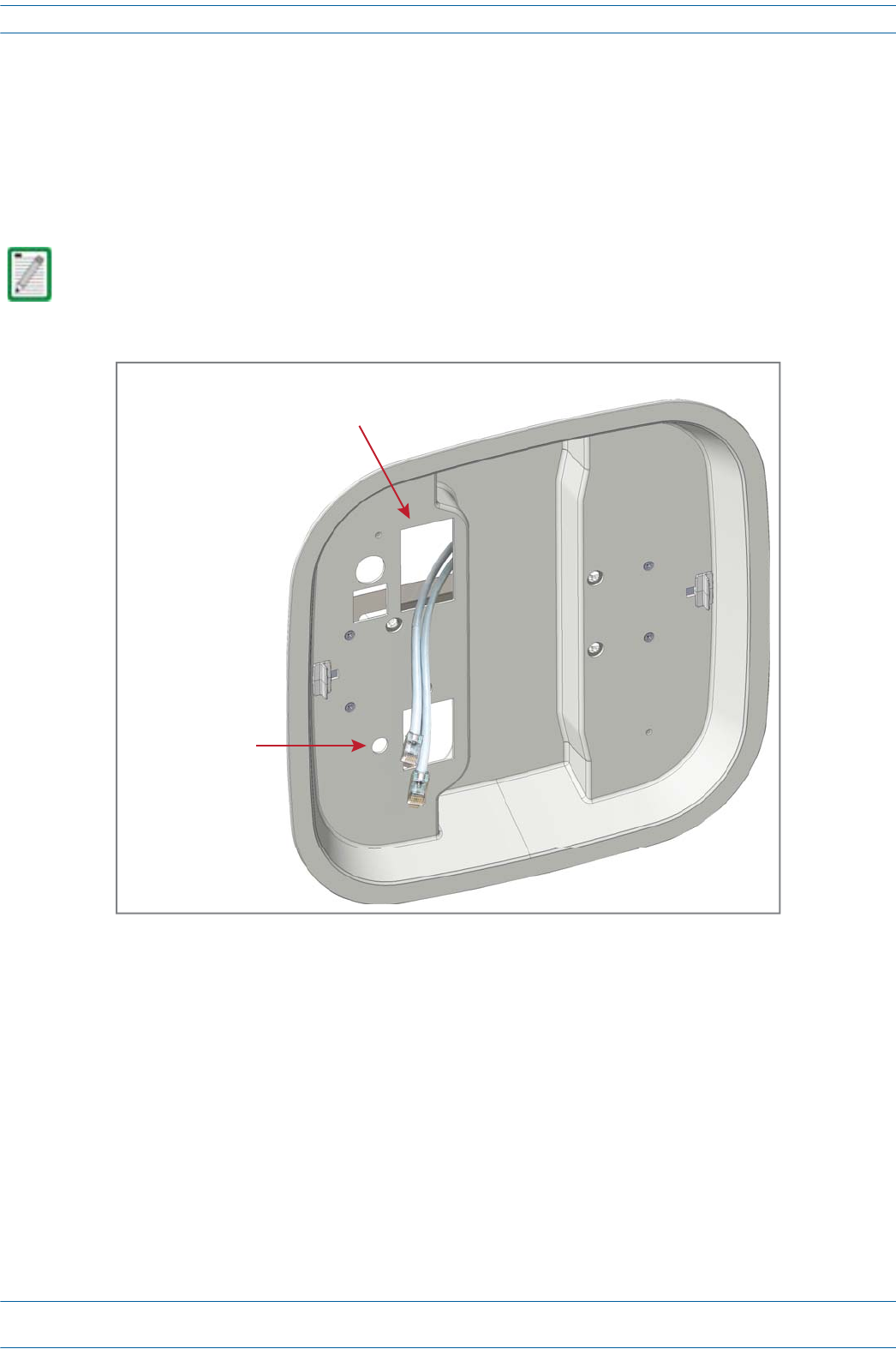
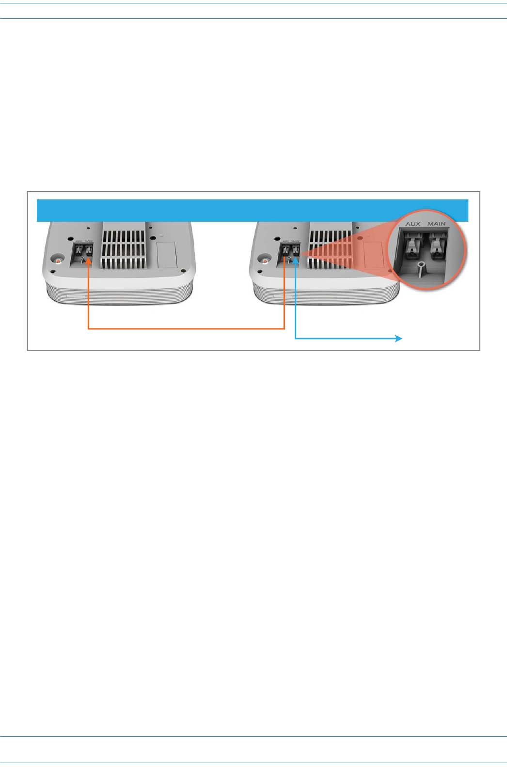
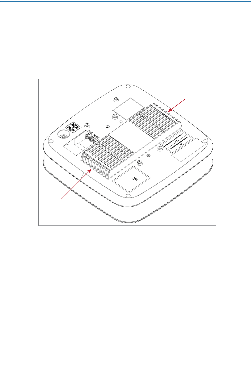
10 RoutetheMAINandAUX(ifneeded)Cat6Acablesthroughtherectangularopeningintheshroud(shown
below),leavingapproximately46cm(18")ofcabletoconnecttotheUAP.Whenviewingtheshroudfrom
thetop,thisopeningislabeledasMAIN.
11 Ifgroundingisrequired,insertanappropriategroundwirethroughthecircularopeningabovetheUAP
groundingscrewasshownleaving46cm(18")ofextragroundwiretoattachtothegroundingscrew.
Grounding is not mandatory. UAPs are classified as low-voltage devices and do not have internal power
supplies. However, CommScope recommends you check local and national electrical codes to determine
if grounding is a requirement for the location in which you are installing the UAP.
Insert the Cat6A cables that connect to the
UAP Main and AUX ports through the largest
rectangular opening.
If required, insert
Ground wire here.
ION®-E Series Hardware Installation Guide M0201AA
Page 62 © June 2017 CommScope, Inc.
Installing UAPs
Install the UAP
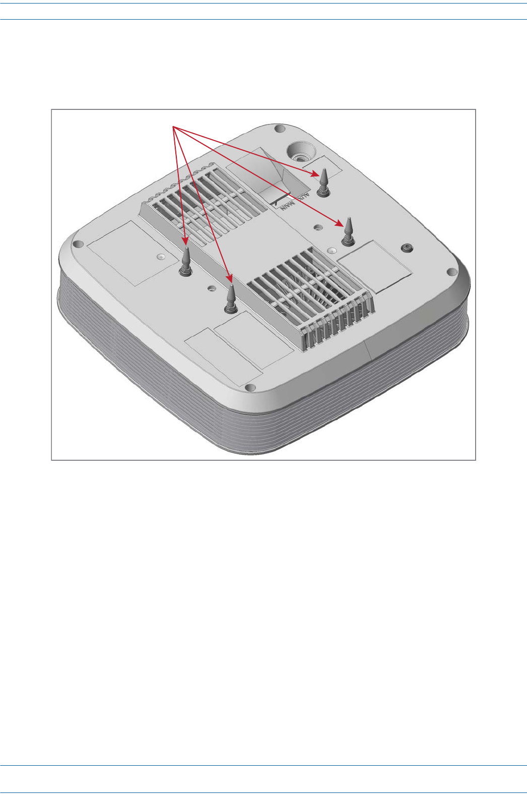
12 InsertthefourUAPGuideLockPinsintothethreadedholesinthetopoftheUAPasshownbelow,and
thenusean8mmmetrictorquewrenchtotightenthemtoatorqueof2.7N-m.
13 WhileholdingtheUAPbelowtheshroud,connecttheCat6AcablestotheMAINandAUXRJ-45portsof
theUAP.
14 Ifrequired,attachthegroundwiretotheUAP'sgreengroundingscrew.
4 Guide Lock Pins
M0201AA ION®-E Series Hardware Installation Guide
© June 2017 CommScope, Inc. Page 63
Installing UAPs
15 AligntheGuideLockPinswiththematingholesintheshroudandguidethecablesbackthroughthe
shroudasyoupresstheUAPupwardintotheshroud—presstheUAPupuntiltheUAPreleaseslidesclick
intoplace,securingtheUAPtotheshroud.MakesuretheUAPissecurelylockedintotheshroudbefore
lettinggooftheunit.
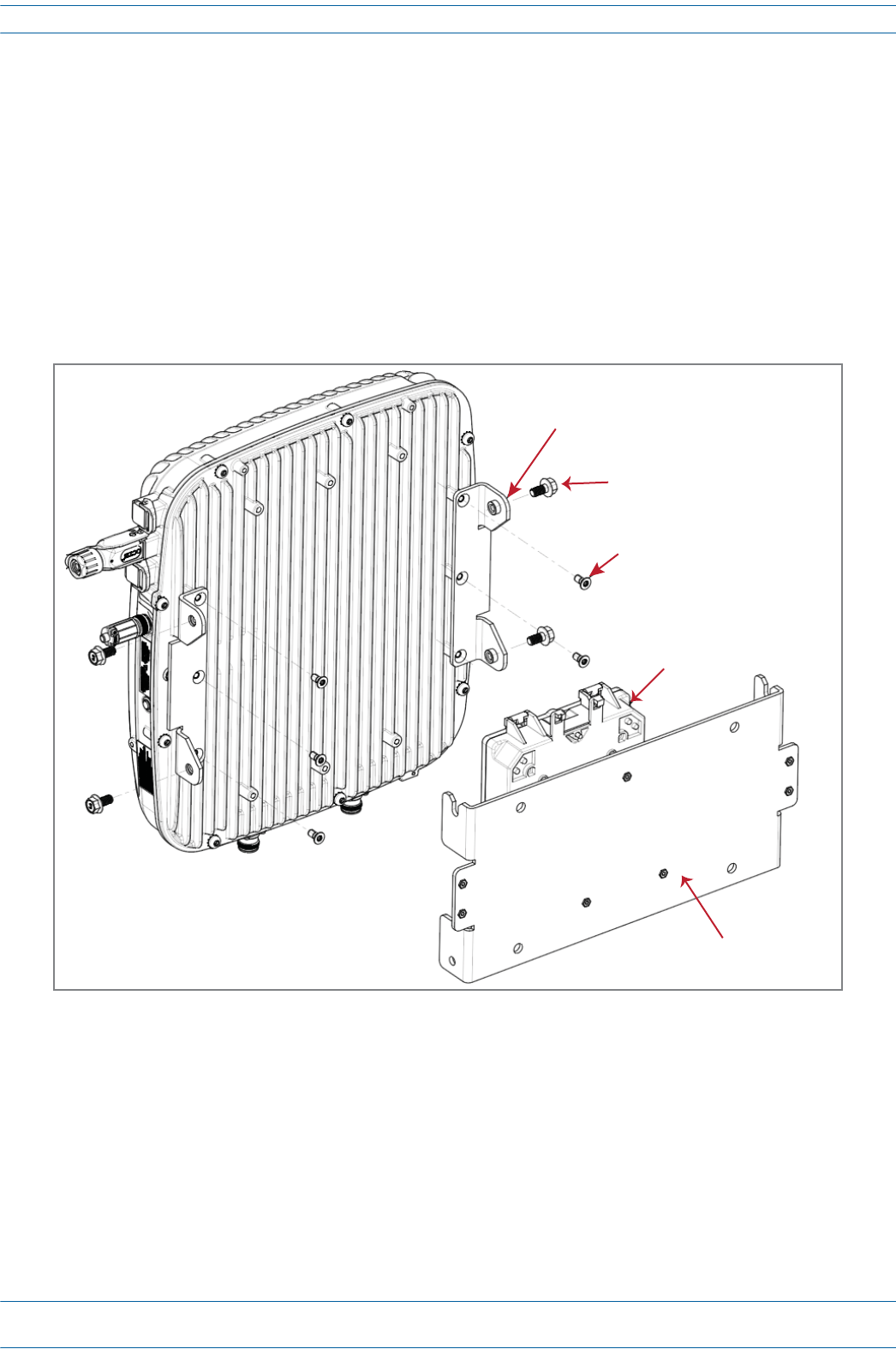
Mounting a UAP to a Wall Using the UAP Wall Mounting Kit
(PN 7683181-00)
ThefollowingsectionsprovidethestepsrequiredtowallmountaUAPusingtheUAPWallMountingKit
(PN7683181-00).
Required Tools for a Wall Mount
•#2Phillips-Headscrewdriver
•Cuttingtooltocutopenceilingtile
ION®-E Series Hardware Installation Guide M0201AA
Page 64 © June 2017 CommScope, Inc.
Installing UAPs
Unpack and Inspect the Wall Mounting Kit
1Inspecttheexterioroftheshippingcontainer(s)forevidenceofroughhandlingthatmayhavedamaged
thecomponentsinthecontainer.
2Unpackeachcontainerwhilecarefullycheckingthecontentsfordamageandverifywiththepackingslip.
3Ifdamageisfoundorpartsaremissing,fileaclaimwiththecommercialcarrierandnotifyCommScope
TechnicalSupport(see"ContactingDCCSGlobalTechnicalSupport”onpage126).Savethedamaged
cartonsforinspectionbythecarrier.
4Saveallshippingcontainersforuseiftheequipmentrequiresshipmentatafuturedate.
Mount the UAP to a Wall
1SelectthelocationtomounttheUAP.
2MounttheWallBrackettoawallusingappropriatefasteners.[PN for the Wall Bracket?]
3ThebracketMUSTbemountedinthecorrectorientationwiththetopofthebracketfacingupward(not
onitssideorupsidedown),asshownbelow.
Table 6-4. Components of the UAP Wall Mounting Kit (PN ??)
Quantity Component Description
1Wall Bracket
The Wall Bracket must be securely mounted to a wall capable of supporting the weight of the UAP (3.2 Kg).
The UAP must
be mounted
with this end up.
Top
(square edges)
Boom
(angeld edges)
Wall Bracket
M0201AA ION®-E Series Hardware Installation Guide
© June 2017 CommScope, Inc. Page 65
Installing UAPs
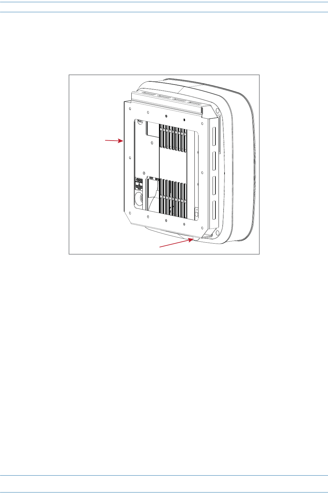
4RemovethefourM5X10mountingscrewslocatedonthebackoftheUAP.
5PlacetheUAPbracketovertheUAPandinsertandtightenthefourM5X10screwstosecurethebracket
totheUAP.
6ConnectCat6AcablestoUAPports.
7IfgroundingisrequiredattachanappropriategroundwiretothegreengroundingscrewoftheUAP.
Grounding is not mandatory. UAPs are classified as low-voltage devices and do not have internal power
supplies. However, CommScope recommends you check local and national electrical codes to determine
if grounding is a requirement for the location in which you are installing the UAP.
UAP
Mounng
Bracket
4 M5x10
Mounng screws
ION®-E Series Hardware Installation Guide M0201AA
Page 66 © June 2017 CommScope, Inc.
Installing UAPs
8AligntheUAPbracketandwallbracket.TheUAPwithUAPbracketattachedmustbeplacedabovethe
wallbracketasshownbelow.
9SlidetheUAPdownwarduntilyouhearitclickandlockintoplaceintheWallBracket.
To ensure that the UAP is securely and safely installed, the wall bracket must be mounted with the top of
the bracket facing upward. Do not install the bracket on its side or facing downward.
Wall Bracket
UAP connected
to a Mounng Bracket

M0201AA ION®-E Series Hardware Installation Guide
© June 2017 CommScope, Inc. Page 67
Installing UAPs
UAP, UAP-N25, and UAP-X Cable Requirements
Cat6AcableisrequiredforallconnectionsbetweenanCATcardandaUAPandforthejumpersbetweenUAPs
incascademode.Thefollowingcablingrulesmustbeobserved;seealsoFigure6-2.
•Plenumratedcablemustbeusedwhereveritisrequiredbylocalelectricalcodes.
•TheminimumCat6AcablewiresizerequiredforusewithUAPsis23AWG(minimumEIA/TIA
standards).
•24AWGistheminimumwiresizeallowedforshortCat6Apatchcablesorjumpers.
•ThemaximumCAT6AcablelengthbetweenaUAPandaCAN/TENis100metersincludingallcables,
jumpers,andpatchpanels.
•ThemaximumcablelengthtoacascadedUAPisalso100meters,whichincludesthefollowing:
–thelengthoftheCat6AjumperbetweentheprimaryUAP'sAUXportandthecascaded(secondary)
UAP'sMAINport
–thecablelengthbetweentheprimaryUAPandtheCAN/TEN.
Forexample,a95mcablebetweenaTENandaprimaryUAPcouldbeusedwitha5mjumpercable
betweentheprimaryandcascadedUAP.
Figure 6-2. UAP, UAP-N25, and UAP-X Cabling Rules
TEN WiFiUAP MM/SM Fiber
Cat6A
No Ethernet device supported for cascaded UAPs
Ethernet device supported for single UAP
CAT6A 100 meters maximum length
A+B≤100 m
AB
ION®-E Series Hardware Installation Guide M0201AA
Page 68 © June 2017 CommScope, Inc.
Installing UAPs
Cascading a UAP, UAP-X, or UAP-N25
TwoUAPscanbeoperatedincascademodetoprovideLTEMIMOcoverageortosupportadditionalbands,
asshowninFigure6-3.TocascadeUAPs,connectaCAT6AcablefromtheAUXportoftheprimaryUAP(A)
totheMAINportofthesecondaryUAP(B).TheAUXportofthesecondary(B)UAPisnotusedincascade
mode.
ItisalsopossibletousethecombinationofaUAPandUAP-Xincascademode,however,allspacingand
externalantennaplacementguidelinesforUAPandUAP-Xunitsstillapply.
TheconnectionofEthernetdevices,however,isnotsupportedforcascadedUAPs.
Figure 6-3. UAP Cascade Options
From UAP(A) AUX port to UAP(B) MAIN port
Primary UAP (A)Secondary UAP (B)
To RFD card port
M0201AA ION®-E Series Hardware Installation Guide
© June 2017 CommScope, Inc. Page 69
UAP Maintenance
UAP MAINTENANCE
ThefollowingsectionstellyouhowtoremoveaUAPfrommountingbrackets,andprovidespreventative
maintenance.
Remove a UAP from a Ceiling Mount
ShouldyouneedtoremovetheUAPfromtheceilingmount,dothefollowing:
1WhileholdingtheUAPwithbothhands,pressbothUAPreleaseslidesinwardtowardstheUAP.
2PresstheredpowerswitchbuttonontheUAPtoshutitdown.TheredbuttonmustbepressedBEFORE
disconnectingtheCAT6Acables.TheblueLEDwillturnoffwhentheunitshutsdown.TheUAPmayalso
beshutdownviasoftwarepriortodisconnectingthecables.
3UnplugtheMAINandAUXCat6Acables.
4Ifagroundwireisinstalled,loosenthegroundingscrewandremovethegroundwire.
Release
slide
Release
slide
View when looking up at UAP in a ceiling mount
ION®-E Series Hardware Installation Guide M0201AA
Page 70 © June 2017 CommScope, Inc.
UAP Maintenance
Remove a UAP from a Wall Mount
ShouldyouneedtoremovetheUAPfromtheceilingmount,dothefollowing:
1WhilesecurelysupportingtheUAP,pressbothUAPreleaseinwardtowardstheUAP.
2PresstheredpowerswitchbuttonontheUAPtoshutitdown.TheredbuttonmustbepressedBEFORE
disconnectingtheCAT6Acables.TheblueLEDwillturnoffwhentheunitshutsdown.TheUAPmayalso
beshutdownviasoftwarepriortodisconnectingthecables.
3UnplugtheMAINandAUXCat6Acables.
4Ifagroundwireisinstalled,loosenthegroundingscrewandremovethegroundwire.
Release tab
Wall Bracket
M0201AA ION®-E Series Hardware Installation Guide
© June 2017 CommScope, Inc. Page 71
UAP Maintenance
Preventative UAP Maintenance
TheUAP,UAP-N25,andUAP-Xdonotrequirepreventativemaintenancemeasures.However,checkingthe
cleanlinessofaunitanditscomponents—particularlytheheatsink/fans—atregularly-scheduledintervals
isrecommended.Avoidapplyingtoomuchpressurewhenusingavacuumorothermethod,asthiscan
damagethefanbearingsandshortenthelifespanofthefans.
YouwillneedtoremovetheUAPunitfromitsmountingtoaccessthefansitsbottom;see"RemoveaUAPfrom
aCeilingMount”onpage69.
Fan
Fan
Boom of an Access Point Unit
(UAP is shown)
ION®-E Series Hardware Installation Guide M0201AA
Page 72 © June 2017 CommScope, Inc.
UAP Specifications
UAP SPECIFICATIONS
UAP Output Specifications
TheManufacturer'sratedoutputpowerforthisequipmentisthecompositepowerinaband.Forsituations
whenmultiplecarriersignalsarepresent,thepowerpercarrierisreduced.Forexample,twocarriersina
bandwilleachhave3dBlesspowerthanasinglecarrierinaband.Thisisimportantwheretheoutputsignal
isradiatedandcancauseinterferencetoadjacentbandusers.Thispowerreductionistobebymeansofgain
reductionandnotbyanattenuatorattheoutputofthedevice.
Lapuissancedesortienominaledufabricantpourcetéquipementestlapuissancecompositedansune
bande.Pourlessituationsoùplusieursporteusessontprésentes,lapuissanceparporteuseestréduite.Par
exemple,deuxporteusesd'unebandeaurontchacun3dBdepuissanceinférieureàcelled'uneseuleporteuse
dansunebande.Ceciestimportantlorsquelesignaldesortieestrayonnéetpeutcauserdesinterférences
auxutilisateursdebandesadjacentes.Cetteréductiondepuissancedoitêtreréaliséeparréductiondegainet
nonparunatténuateurensortiedudispositif.
UAP UAP-X UAP-N25
Nominal passband gain per band:
Le gain nominal en bande passante
20 dB 20 dB
Rated mean output power per band 380 MHz - 512 MHz
La puissance moyenne de sortie par bande 380 MHz - 512 MHz
N/A +8 dBm
Rated mean output power per band >608 MHz
La puissance moyenne de sortie par bande >608 MHz
+18 dBm +18 dBm +18 dBm
Maximum combined mean power in mid bands 608-1000 MHz
Puissance moy-enne combinée maximale dans les bandes moyennes 608-1000 MHz
+21 dBm +21 dBm +21 dBm
Maximum combined mean power in high bands 1395-2700 MHz
Puissance moy-enne combinée maximale dans les bandes moyennes 1395-2700 MHz
+21 dBm +21 dBm +21 dBm
Input / Output Impedance
Les impédances d'entrée et de sortie, et
50 Ohms 50 Ohms 50 Ohms
M0201AA ION®-E Series Hardware Installation Guide
© June 2017 CommScope, Inc. Page 73
UAP Specifications
UAP Bandwidth Specifications
ION-Esupportsavarietyofbandsinthe380to2700MHzrange.Thefrequenciesandbandwidthslistedin
thefollowingtable,forexample,representthenominalbandwidthspecificationsforCanadaintheNorth
Americaregion.
MHz MHz Nominal bandwidth (MHz)
La largeur de bande nominale
406.1* 430* 24
450* 470* 20
728 746 18
746 756 10
768 776 8
851 869 18
869 894 25
1930 1995 65
2110 2155 45
2620 2690 70
* UAP-X, which uses external antennas, is
required to support frequencies below
608 MHz due to the UAP's internal
antenna limitations at lower frequencies.

ION®-E Series Hardware Installation Guide M0201AA
Page 74 © June 2017 CommScope, Inc.
UAP Specifications

M0201AA ION®-E Series Hardware Installation Guide
© June 2017 CommScope, Inc. Page 75
Chapter Topics Page
Identifying CAP Ls in the ION-E Software ............................................................................................................................................................ 76
CAP L Overview............................................................................................................................................................................................... 77
CAP L Connectors, Ports, and LEDs........................................................................................................................................................... 78
CAP L with an Optical Fiber Interface....................................................................................................................................................... 79
CAP L with a Copper Interface and External DC Power............................................................................................................................ 80
CAP L with a Copper Interface and Power Cat 6A Cable .......................................................................................................................... 81
Fan Interface Port..................................................................................................................................................................................... 82
Powering a CAP L...................................................................................................................................................................................... 82
CAP L Accessory Options .......................................................................................................................................................................... 83
Fan Kit (PN 7724090-00) .................................................................................................................................................................... 84
CAP L Flat Mounting Bracket Kit (PN 7774353-00) ............................................................................................................................ 85
CAP L Power Supply / Hybrid Fiber Mounting Kit (PN 7774354-00) .................................................................................................. 86
CAP L 240W AC/DC Power Supply Kit (PN 7775087-00) .................................................................................................................... 87
CAP OCTIS Kits (PNs 7773582-00 and 7760652-00)........................................................................................................................... 88
Installing CAP Ls................................................................................................................................................................................................... 89
Prepare for Installation................................................................................................................................................................................... 89
Recommended Tools................................................................................................................................................................................ 89
Recommended Materials.........................................................................................................................................................................89
Determine the Power Consumption of the CAP L.................................................................................................................................... 90
Determine the CAP L Mounting Site ........................................................................................................................................................ 90
Mounting Orientation .............................................................................................................................................................................. 93
Mounting Cautions................................................................................................................................................................................... 95
General Installation Safety Requirements ............................................................................................................................................... 95
Guard Against Damage from Electro-Static Discharge............................................................................................................................. 95
Unpack and Inspect the CAP L and Optional Accessories ........................................................................................................................ 96
Installing a CAP L.............................................................................................................................................................................................96
Mount the CAP L ...................................................................................................................................................................................... 96
Flat-Surface Mount a CAP L ............................................................................................................................................................... 97
Wall Mount a CAP L Using a Flat Mounting Bracket Kit (PN 7774353-00)......................................................................................... 97
Wall Mount a CAP L Using a Power Supply / Hybrid Fiber Mounting Kit (PN 7774354-00)............................................................. 100
Wall Mount a CAP L Using a 240W AC/DC Power Supply Kit (PN 7775087-00)...............................................................................106
Ceiling Mount a CAP L......................................................................................................................................................................109
(Optional) Ground the CAP L..................................................................................................................................................................110
Connect the CAP L Cables.......................................................................................................................................................................111
Cable a CAP L with an Optical Fiber Interface..................................................................................................................................111
Cable a CAP L with a Copper Interface and Power over Category 6A Cable.................................................................................... 114
Cable a CAP L with a Copper Interface and Power over Ethernet ...................................................................................................116
Cascading CAP Ls ............................................................................................................................................................................................... 118
CAP L Maintenance ........................................................................................................................................................................................... 119
Remove a CAP L from a Ceiling Mount......................................................................................................................................................... 119
Remove a CAP L from a Wall Mount ............................................................................................................................................................ 120
Preventative CAP L Maintenance ................................................................................................................................................................. 121
CAP L Specifications...........................................................................................................................................................................................122
CAP L Output Specifications ......................................................................................................................................................................... 122
CAP L Bandwidth Specifications.................................................................................................................................................................... 123
ThischapterprovidesaproductoverviewandinstallationinstructionsfortheION-ESeriesCarrierAccess
Point,LowPower(CAPL)thatcanbedeployedinanION-Esystem.CAPLsallowtransmissionbetweenthe
ION-EequipmentandantennasandEthernetdevices(suchasWiFiandIPcameras).
ForinformationonUniversalAccessPoints(UAPS),goto"UniversalAccessPoints”onpage49.
CARRIER ACCESS POINT, LOW POWER (CAP L) 7
ION®-E Series Hardware Installation Guide M0201AA
Page 76 © June 2017 CommScope, Inc.
Identifying CAP Ls in the ION-E Software
IDENTIFYING CAP LS IN THE ION-E SOFTWARE
CAPLnumberingisbasedontheCATcardsslotandportnumbersintheassociatedCANorTENandwhether
theCAPLisdirectlyconnectedtotheCATcard(a)orconnectedtotheAUXportofanotherUAP(b).
TheION-EGUIlabelsCAPLsasfollows:
OAP.<Slot ID>.<Port#><a or b>
Where
•OAPidentifiesthattheAccessPointisaCAPL
•<Slot ID>istheWCS-2orWCS-4Subrackslot(L1toL8),shownasaalpha-numericalintegerfromL1-L8
•<Port #>istheCATCardPortnumber(1-4),shownasanumericalintegerfrom1-4
•<a or b>iswhethertheCAPListhemain/primaryCAPL(a)orthecascaded/secondaryCAPL(b).
Table 7-1. UAP Identification in the ION-E Software
WCS Slot CAT Port Primary CAP L
(Direct Connect)
Secondary CAP L
(AUX Port Connect)
WCS Slot CAT Port Primary CAP L
(Direct Connect)
Secondary CAP L
(AUX Port Connect)
L1 1OAP.L1.1a OAP.L1.1b L5 1OAP.L5.1a OAP.L5.1b
L1 2OAP.L1.2a OAP.L1.2b L5 2OAP.L5.2a OAP.L5.2b
L1 3OAP.L1.3a OAP.L1.3b L5 3OAP.L5.3a OAP.L5.3b
L1 4OAP.L1.4a OAP.L1.4b L5 4OAP.L5.4a OAP.L5.4b
L2 1OAP.L2.1a OAP.L2.1b L6 1OAP.L6.1a OAP.L6.1b
L2 2OAP.L2.2a OAP.L2.2b L6 2OAP.L6.2a OAP.L6.2b
L2 3OAP.L2.3a OAP.L2.3b L6 3OAP.L6.3a OAP.L6.3b
L2 4OAP.L2.4a OAP.L2.4b L6 4OAP.L6.4a OAP.L6.4b
L3 1OAP.L3.1a OAP.L3.1b L7 1OAP.L7.1a OAP.L7.1b
L3 2OAP.L3.2a OAP.L3.2b L7 2OAP.L7.2a OAP.L7.2b
L3 3OAP.L3.2a OAP.L3.2b L7 3OAP.L7.2a OAP.L7.2b
L3 4OAP.L3.4a OAP.L3.4b L7 4OAP.L7.4a OAP.L7.4b
L4 1OAP.L4.1a OAP.L4.1b L8 1OAP.L8.1a OAP.L8.1b
L4 2OAP.L4.2a OAP.L4.2b L8 2OAP.L8.2a OAP.L8.2b
L4 3OAP.L4.3a OAP.L4.3b L8 3OAP.L8.3a OAP.L8.3b
L4 4OAP.L4.4a OAP.L4.4b L8 4OAP.L8.4a OAP.L8.4b
M0201AA ION®-E Series Hardware Installation Guide
© June 2017 CommScope, Inc. Page 77
Identifying CAP Ls in the ION-E Software
CAP L Overview
TheCommScopeION-ECarrierAccessPoint,LowPower(CAPL)providesdataandpowerthroughCopper,
Single-ModeFiber(SMF),orMulti-ModeFiber(MMF).Inadditiontotransmittingwirelessdataovera
commoncable,theCAPLalsosupportsGigabitEthernetforWiFi,IPcameras.
TheCAPLinterfaceswiththeION-ECAN/TENviaaCAT6Acable,orviaanopticallink.Onthedownlink,the
CAPLconvertssomeorallofthedataarrivingattheCAPLtoanalogsignalsandsendsthemtotheAntenna
ports.Ontheuplink,receivedsignalsaredigitizedandserializedintodatastreams,whicharesentbacktothe
CAN.EachCAPLcanprovideRFcoverageforuptofourspecificfrequencybands.
TheCAPL
•ispassivelycooledwithatemperaturerangeof-33°Cto+40°C(-27.4°Fto104°F);seealso"FanKit(PN
7724090-00)”onpage84
•isoutdoorrated(IP67)
•hasatypicalpowerconsumptionof98W;seealso"FanKit(PN7724090-00)”onpage84
Table7-2liststheCAPLmodelsthatthisinstallationguidesupports.
Table 7-2. CAP L Models and RF Variations
Part Number Model Name Frequency Bands Supported
Remotes
Interface
Type
Power Option
Available
Fan
Kit
7770203-0001 CAP L 17E/17E/23/23 C-PE-F1 AWS1700 / LTE2300 17E/23 MIMO Copper Power over Cat6A Yes
7770203-0002 CAP L 17E/17E/23/23 C-DC-F1 AWS1700 / LTE2300 17E/23 MIMO Copper External DC Yes
7770203-0003 CAP L 17E/17E/23/23 F-DC-F1 AWS1700 / LTE2300 17E/23 MIMO Optical External DC Yes
7770203-0004 CAP L 17E/17E/23/23 C-PE AWS1700 / LTE2300 17E/23 MIMO Copper Power over Cat6A No
7770203-0005 CAP L 17E/17E/23/23 C-DC AWS1700 / LTE2300 17E/23 MIMO Copper External DC No
7770203-0006 CAP L 17E/17E/23/23 F-DC AWS1700 / LTE2300 17E/23 MIMO Optical External DC No
7770209-0001 CAP L 18/21/26/26 C-PE-F1 GSM1800 / UMTS2100 / LTE2600 18/21/26/26 Copper Power over Cat6A Yes
7770209-0002 CAP L 18/21/26/26 C-DC-F1 GSM1800 / UMTS2100 / LTE2600 18/21/26/26 Copper External DC Yes
7770209-0003 CAP L 18/21/26/26 F-DC-F1 GSM1800 / UMTS2100 / LTE2600 18/21/26/26 Optical External DC Yes
7770209-0004 CAP L 18/21/26/26 C-PE GSM1800 / UMTS2100 / LTE2600 18/21/26/26 Copper Power over Cat6A No
7770209-0005 CAP L 18/21/26/26 C-DC GSM1800 / UMTS2100 / LTE2600 18/21/26/26 Copper External DC No
7770209-0006 CAP L 18/21/26/26 F-DC GSM1800 / UMTS2100 / LTE2600 18/21/26/26 Optical External DC No
7770356-0001 CAP L 17E/17E/19/19 C-PE-F1 AWS1700 / PCS1900 17E/19 MIMO Copper Power over Cat6A Yes
7770356-0002 CAP L 17E/17E/19/19 C-DC-F1 AWS1700 / PCS1900 17E/19 MIMO Copper External DC Yes
7770356-0003 CAP L 17E/17E/19/19 F-DC-F1 AWS1700 / PCS1900 17E/19 MIMO Optical External DC Yes
7770356-0004 CAP L 17E/17E/19/19 C-PE AWS1700 / PCS1900 17E/19 MIMO Copper Power over Cat6A No
7770356-0005 CAP L 17E/17E/19/19 C-DC AWS1700 / PCS1900 17E/19 MIMO Copper External DC No
7770356-0006 CAP L 17E/17E/19/19 F-DC AWS1700 / PCS1900 17E/19 MIMO Optical External DC No

ION®-E Series Hardware Installation Guide M0201AA
Page 78 © June 2017 CommScope, Inc.
Identifying CAP Ls in the ION-E Software
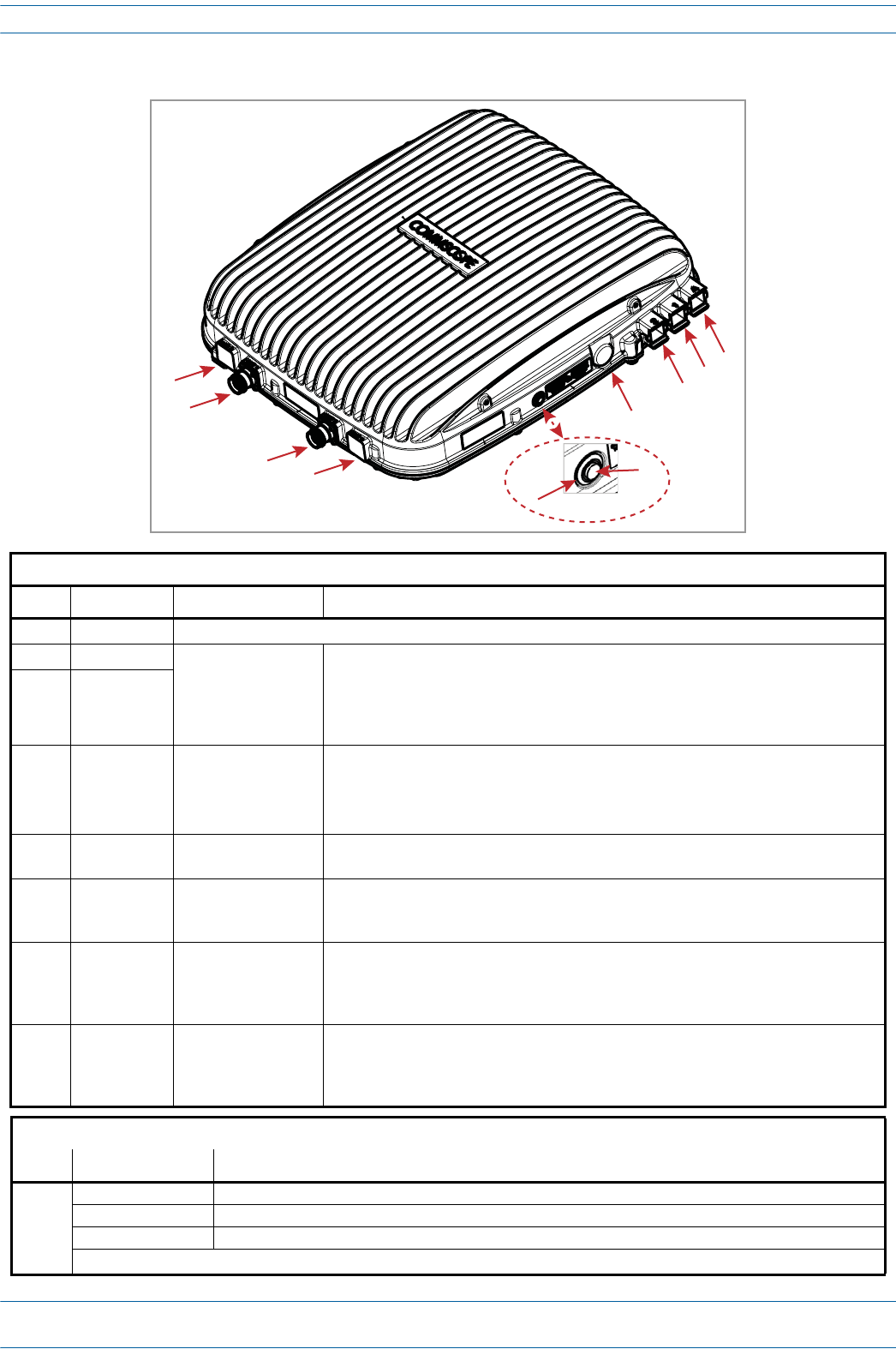
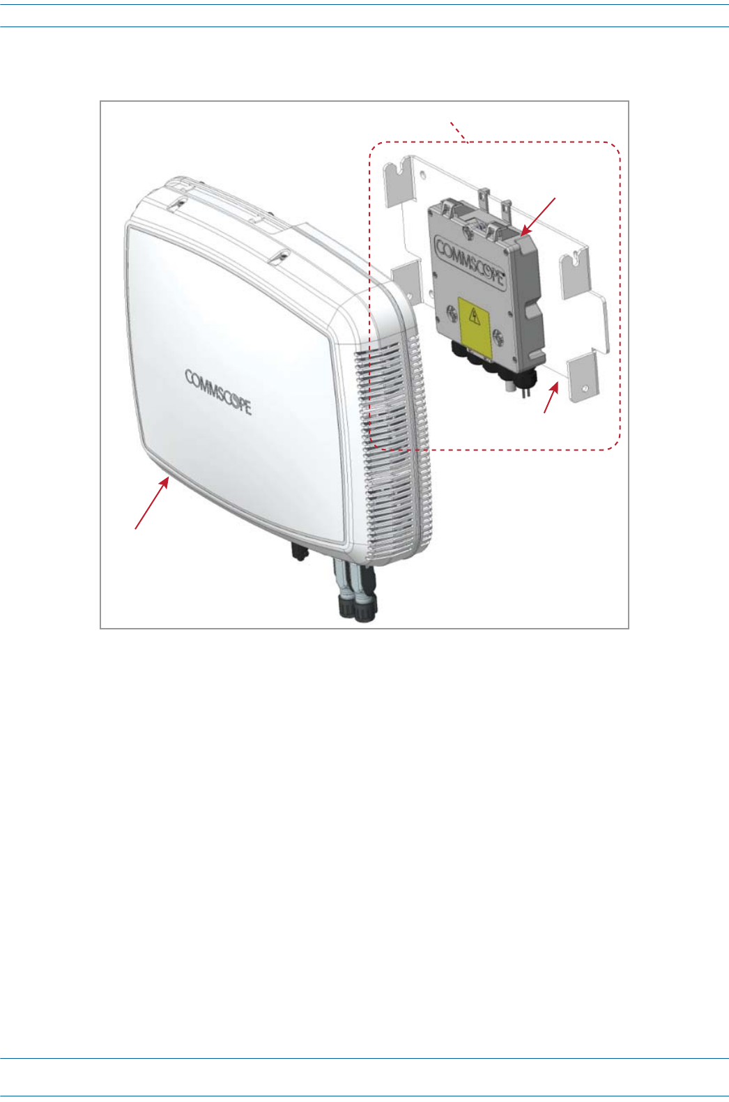
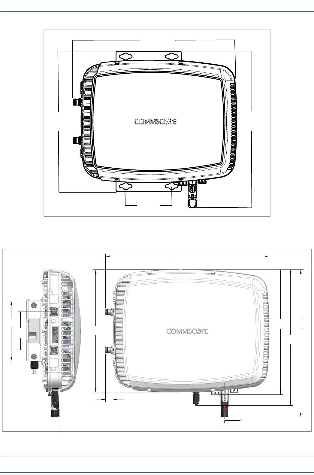
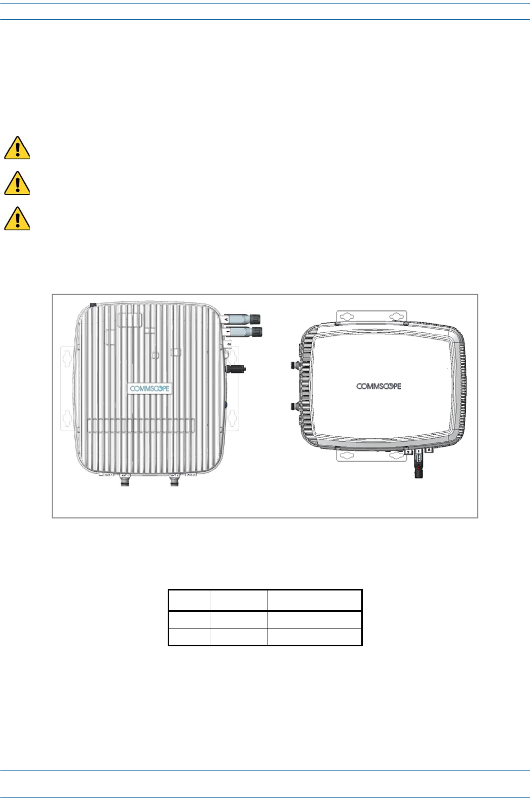
CAP L Connectors, Ports, and LEDs
Thefollowingsectionsidentifytheconnectors,ports,andLEDsavailableonthedifferentCAPLmodels:
•"CAPLwithanOpticalFiberInterface”onpage79
•"CAPLwithaCopperInterfaceandExternalDCPower”onpage80
•"CAPLwithaCopperInterfaceandPowerCat6ACable”onpage81.
M0201AA ION®-E Series Hardware Installation Guide
© June 2017 CommScope, Inc. Page 79
Identifying CAP Ls in the ION-E Software
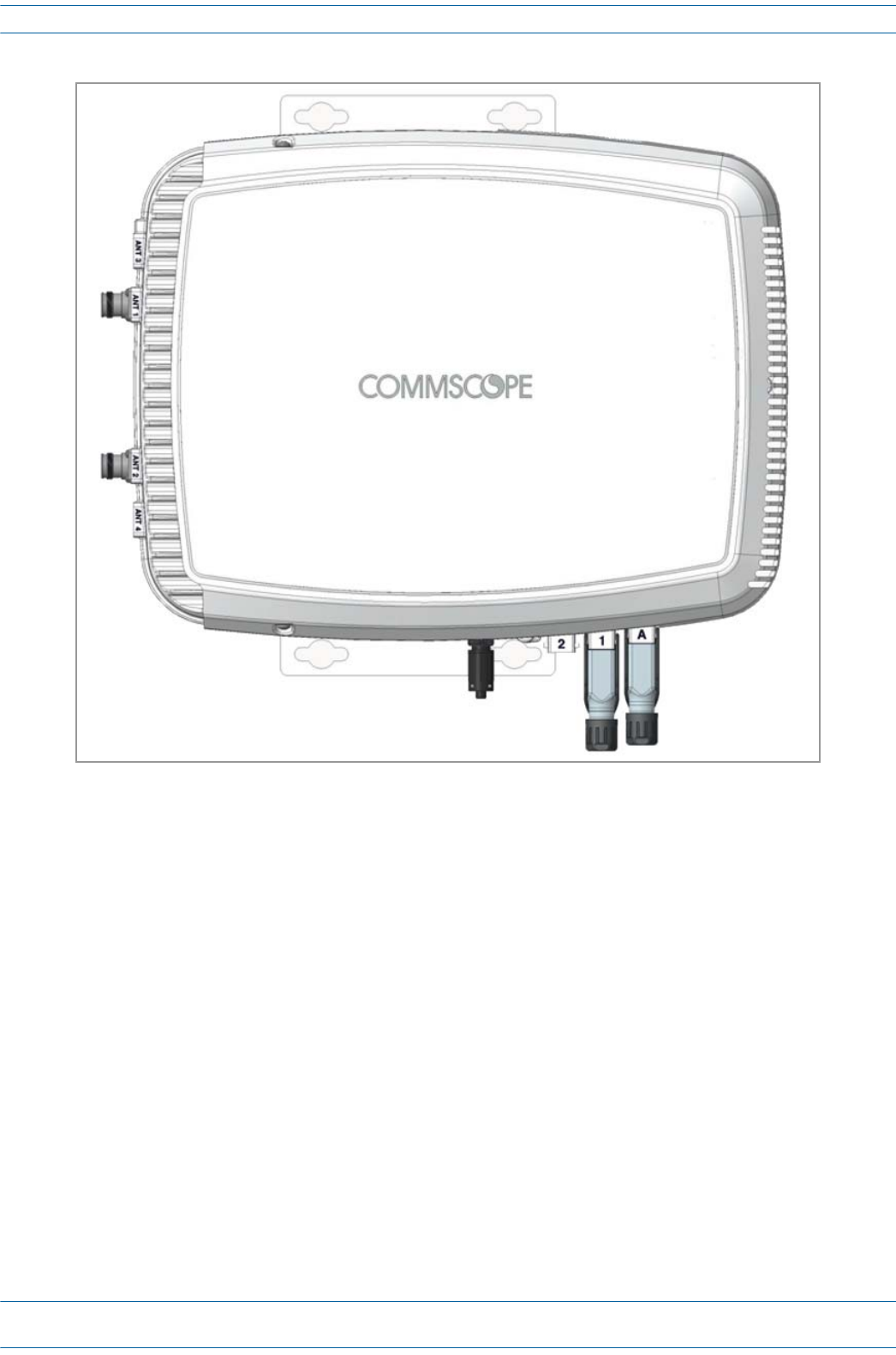
CAP L with an Optical Fiber Interface
Connectors
REF # Label Description Function
1, 4 ANT 3, ANT 4 Not available; connector is plugged.
2ANT 1
4.3-10 RF connector
RF connectors that connect to two separate external antennas or to two ports on a
cross-polarized dual antenna via 50Ω coaxial cable. Each connector supports two RF
bands as described in Table 7-2 on page 77. The end of the 50Ω coaxial cable that
connects to an ANT connector can be either a push-pull or a threaded connector. If not
used, an ANT connector must be plugged.
3ANT 2
6 Unlabeled Pushbutton switch Turns power to CAP L on/off. Power to the CAP L may also be shutdown via the ION-E
Series Software. [verify can power off via GUI]
CAUTION! Prior to disconnecting the Power cable from the CAP L, press the Power
button to power off the CAP L.
7 Unlabeled 36 to 60 Vdc Power
connector
Proprietary 4-pin connector that connects to a local or remote DC power supply, or to a
Hybrid Fiber Junction Box.
8 2 Optical Port 2 Optical Port 2 connects to an optional cascaded CAP L unit and provides the main signal
interface. Optical transport occurs over Single Mode Fiber (SMF) or Multi Mode Fiber
(MMF). This port must be plugged if not in use.
9 1 Optical Port 1 Optical Port 1 connects to an ION-E CAN/TEN (possibly through a local Hybrid Fiber
Junction Box) and provides the main signal interface. Optical transport occurs over Single
Mode Fiber (SMF) or Multi Mode Fiber (MMF); the appropriate SFP+ is factory-installed
according to order specifications.
10 A Auxiliary port The AUX port provides a connection for external Ethernet devices such as WiFi and IP
cameras. Cabling is via the appropriate CAT cable for the protocol; this model supports an
1000 BASE-T and 802.3at Class 3 Power over Cat6A Ethernet connection. Maximum
attached cable length is 3 meters (9.8 feet). The AUX port must be plugged if not in use.
Power LED (unlabeled)
Ref # LED Color Description
5• Blue • CAP L is powered on and operational.
• Flashing blue • CAP L is powered on and initializing.
• Off • CAP L is not powered on.
For further information, see "Powering a CAP L” on page 82.
1
2
34
7
8
910
5
6
ION®-E Series Hardware Installation Guide M0201AA
Page 80 © June 2017 CommScope, Inc.
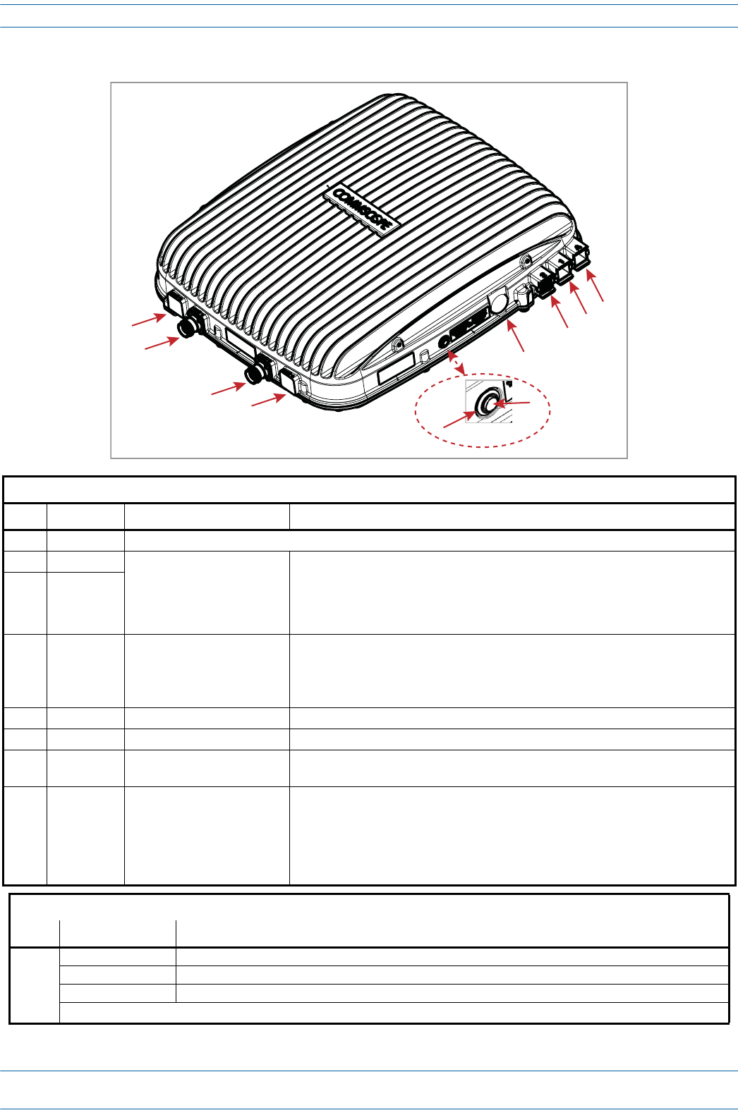
Identifying CAP Ls in the ION-E Software
CAP L with a Copper Interface and External DC Power
Connectors
REF # Label Description Function
1, 4 ANT 3, ANT 4 Not available; connector is plugged.
2ANT 1
4.3-10 RF connector
RF connectors that connect to two separate external antennas or to two ports on a
cross-polarized dual antenna via 50Ω coaxial cable. Each connector supports two RF
bands as described in Table 7-2 on page 77. The end of the 50Ω coaxial cable that
connects to an ANT connector can be either a push-pull or a threaded connector. If not
used, an ANT connector must be plugged.
3ANT 2
6 Unlabeled Pushbutton switch Turns power to CAP L on/off. Power to the CAP L may also be shutdown via the ION-E
Series Software. [verify can power off via GUI]
CAUTION! Prior to disconnecting the Power cable from the CAP L, press the
Power button to power off the CAP L.
7 Unlabeled 36 to 60 Vdc Power connector Connects to local or remote power.
8 2 Port 2 Plugged, not applicable to this model configuration.
9 1 Port 1 Port 1 connects to an ION-E CAN/TEN via CAT 6A cable and provides the main signal
interface.
10 A RJ-45 connector The AUX port provides a cascade connection to an optional locally powered cascaded
CAP L, or provides a connection to external Ethernet devices such as WiFi and IP
cameras. Cabling is via the appropriate CAT cable for the protocol; this model supports
an 1000 BASE-T and 802.3at Class 3 Power over Cat6A Ethernet connection. Maximum
attached cable length is 3 meters (9.8 feet). The AUX port must be plugged if not in
use.
Power LED (unlabeled)
Ref # LED Color Description
5• Blue • CAP L is powered on and operational.
• Flashing blue • CAP L is powered on and initializing.
• Off • CAP L is not powered on.
For further information, see "Powering a CAP L” on page 82.
1
2
34
7
8
910
5
6

M0201AA ION®-E Series Hardware Installation Guide
© June 2017 CommScope, Inc. Page 81
Identifying CAP Ls in the ION-E Software
CAP L with a Copper Interface and Power Cat 6A Cable
Connectors
REF # Label Description Function
1, 4 ANT 3, ANT 4 Not available; connector is plugged.
2ANT 1
4.3-10 RF connector
RF connectors that connect to two separate external antennas or to two ports on a
cross-polarized dual antenna via 50Ω coaxial cable. Each connector supports two RF
bands as described in Table 7-2 on page 77. The end of the 50Ω coaxial cable that
connects to an ANT connector can be either a push-pull or a threaded connector. If not
used, an ANT connector must be plugged.
3ANT 2
6 Unlabeled Pushbutton switch Turns power to CAP L on/off. Power to the CAP L may also be shutdown via the ION-E
Series Software. [verify can power off via GUI]
CAUTION! Prior to disconnecting the Power cable from the CAP L, press the
Power button to power off the CAP L.
7 Unlabeled 36 to 60 Vdc Power connector Plugged, not applicable to this model configuration.
8 2 Port 2 Plugged, not applicable to this model configuration.
9 1 Port 1 Port 1 connects to an ION-E CAN/TEN via CAT 6A cable and provides the main signal
and power interface.
10 A RJ-45 connector The AUX port provides a cascade connection to an optional locally powered secondary
CAP L, or provides a connection to external Ethernet devices such as WiFi and IP
cameras. Cabling is via the appropriate CAT cable for the protocol; this model supports
an 1000 BASE-T and 802.3at Class 3 Power over Cat6A Ethernet connection. Maximum
attached cable length is 3 meters (9.8 feet). The AUX port must be plugged if not in use.
Power LED (unlabeled)
Ref # LED Color Description
5• Blue • CAP L is powered on and operational.
• Flashing blue • CAP L is powered on and initializing.
• Off • CAP L is not powered on.
For further information, see "Powering a CAP L” on page 82.
1
2
34
7
8
910
5
6
ION®-E Series Hardware Installation Guide M0201AA
Page 82 © June 2017 CommScope, Inc.
Identifying CAP Ls in the ION-E Software
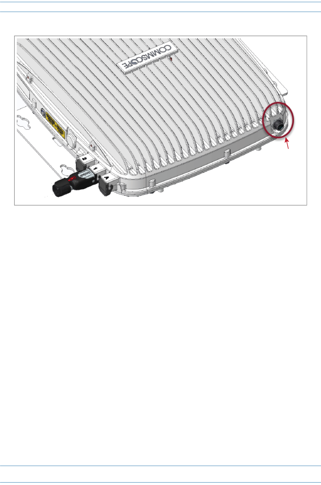
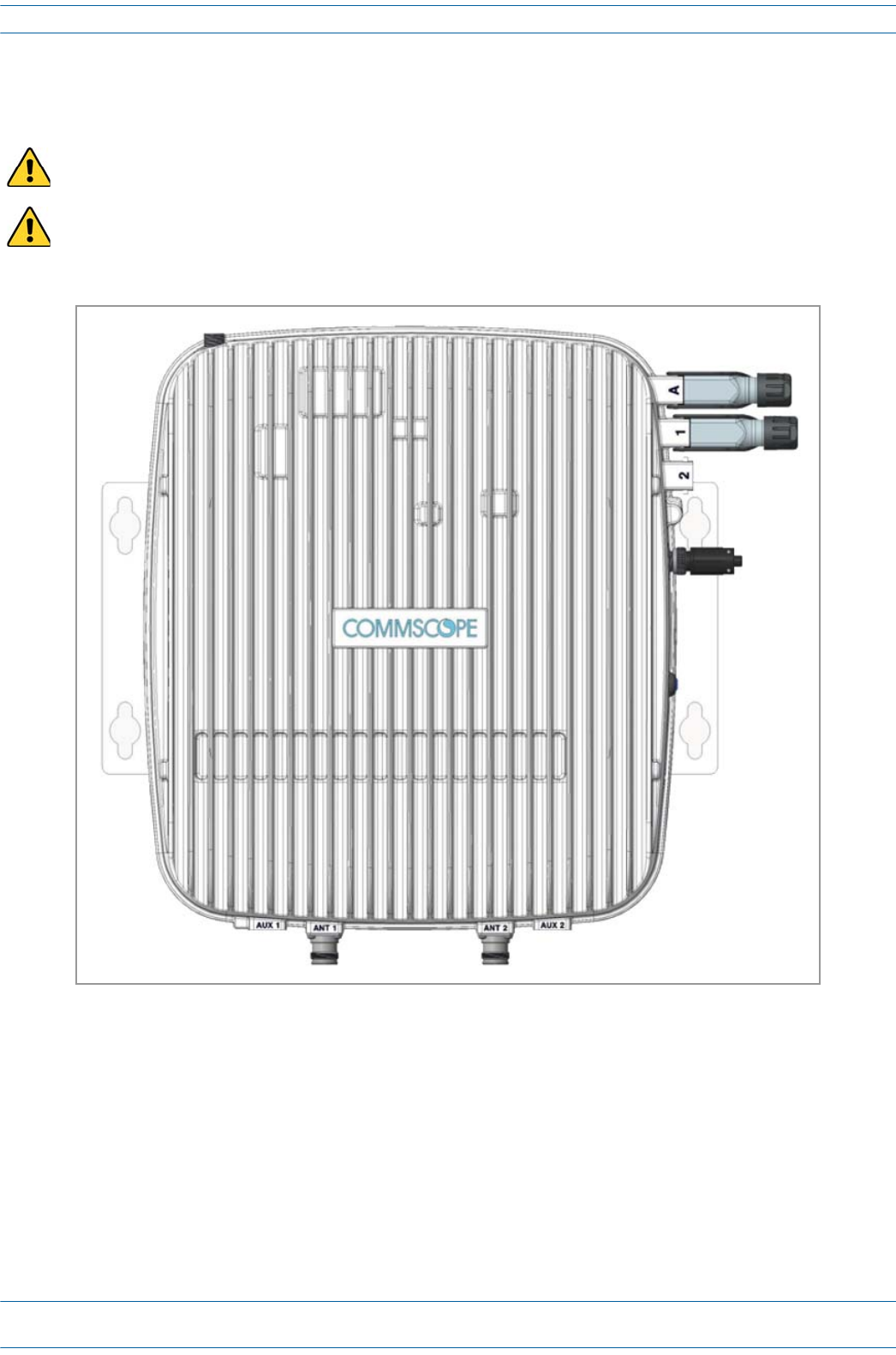
Fan Interface Port
Theprecedinggraphicshowstheproprietary8-pinFanInterfaceport,whichisavailableonallCAPLmodels.
FanKitsarefactoryinstalled.IftheFanKitwasordered,theFanInterfaceportwillbecabledtotheFanKit
atthefactory.IfaFanKitisnotordered,theFanInterfaceportisplugged.
Powering a CAP L
TheCAPLPower-Downbuttonisusedonlytopowerdowntheunit.Undernormaloperatingconditions,the
PowerLEDrespondsaslistedbelow.
•IftheCAPLispoweredbyalocalpowersupply,theCAPLunitisalwayspoweredon.
•IftheCAPLispoweredoveradatacable(Cat6Aorfiber),theCAPLisautomaticallydetectedbythe
WCS/TENandthelink(power)comesup.
•IftheCAPLispoweredoverCATcablingorthehead-endDC(hybridfiber)supplyisused,theCAPLis
automaticallydetectedandpoweredwhenitisconnectedtotheWCS/TEN.
Inanycase,thePowerLEDturnsonbrieflywhentheunitisfirstdetected.Itwillthengooutbriefly,followed
byaninitializationperiodduringwhichthePowerLEDflashesslowlywhiletheCAPLisconfigured.TheLED
willremainasteadyblue(notflashing)oncetheunitreachesafullyoperationalstate,whichtypicallyoccurs
within45seconds,butitcanvarydramaticallyindifferentsystemsandconfigurations,especiallyifit's
auto-updating.
Fan
Interface
port

M0201AA ION®-E Series Hardware Installation Guide
© June 2017 CommScope, Inc. Page 83
Identifying CAP Ls in the ION-E Software
CAP L Accessory Options
ThefollowingsectionsdescribehardwareoptionsfortheCAPL:
•"FanKit(PN7724090-00)”onpage84
•"CAPLFlatMountingBracketKit(PN7774353-00)”onpage85
•"CAPLPowerSupply/HybridFiberMountingKit(PN7774354-00)”onpage86
•"CAPL240WAC/DCPowerSupplyKit(PN7775087-00)”onpage87
•"CAPOCTISKits(PNs7773582-00and7760652-00)”onpage88.
ION®-E Series Hardware Installation Guide M0201AA
Page 84 © June 2017 CommScope, Inc.
Identifying CAP Ls in the ION-E Software
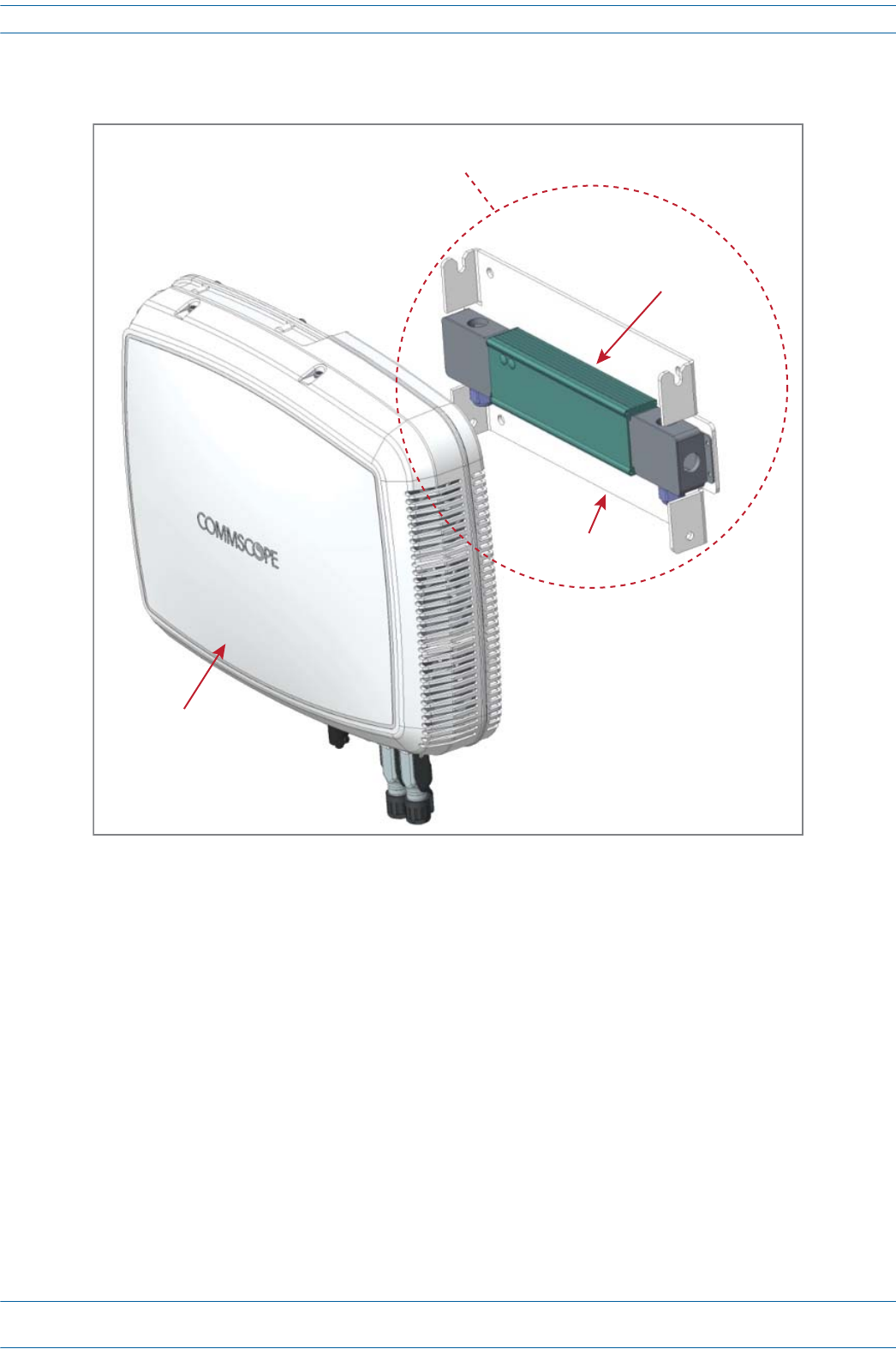
Fan Kit (PN 7724090-00)
TheoptionalFanKit(CommScopePN7724090-00)isanintegratedshroudthatfitsovertheCAPLenclosure
toextendtheupperambienttemperaturerange.TheFanKit
•isIP55rated
•increasesthepassivelycooledtemperaturerangeto-33°Cto+55°C(-27.4°Fto131°F)
•requiresthattheCAPLbeinstalledinahorizontalpositionasshownabove
•adds7WpowerconsumptiontotheCAPL;thismeansthatiftheCAPLisutilizingallofitssubbandsand
ispoweringanexternal1GbEthernetdevice(20WattheAUXport),theCAPL’spowerconsumptioncan
beashighas125W.
•isfactoryinstalled,butcanbereplacedinthefield.
Table7-3liststheFanKitcomponents.
Table 7-3. Fan Kit (PN 7724090-00)
Quantity Part Number Component
1Fan Shroud
1Fan Harness
Fan Kit
M0201AA ION®-E Series Hardware Installation Guide
© June 2017 CommScope, Inc. Page 85
Identifying CAP Ls in the ION-E Software
CAP L Flat Mounting Bracket Kit (PN 7774353-00)
TheCAPLFlatMountingBracketKit(CommScopePN7774353-00)providesthemountingbracketsrequired
tomountanCAPLtoawallorotherflatsurface.
Flat Mounng Brackets
ION®-E Series Hardware Installation Guide M0201AA
Page 86 © June 2017 CommScope, Inc.
Identifying CAP Ls in the ION-E Software
CAP L Power Supply / Hybrid Fiber Mounting Kit (PN 7774354-00)
TheCAPLPowerSupply/HybridFiberMountingKit(CommScopePN7774354-00)separatesthepower
fromthefibersignalsonahybridfiberfeedfromtheCAN/TEN.
UNRESOLVED: We need to add information as to why would a customer would purchase this option. We
need to make a statement such as, “Use a Power Supply / Hybrid Fiber Mounting Kit when
the CAP L must be powered by …”
CAP with
oponal
Fan Kit
Hybrid Fiber
Splice Box
Mounng
Bracket
Hybrid Fiber Mounng Bracket Kit
M0201AA ION®-E Series Hardware Installation Guide
© June 2017 CommScope, Inc. Page 87
Identifying CAP Ls in the ION-E Software
CAP L 240W AC/DC Power Supply Kit (PN 7775087-00)
TheCAPL240WAC/DCPowerSupplyKit(CommScopePN7775087-00)providesa240W,48VExternal
PowerSupplythatconvertslocalACpowertoDCpowerfortheCAPL.
UNRESOLVED: We need to add information as to why would a customer would purchase this option. We
need to make a statement such as, “Use a 240W AC/DC Power Supply Kit when the CAP L
must be powered by …”
CAP with
oponal
Fan Kit
240 W Power Supply,
48V
Mounng
Bracket
Close-Coupled Power Supply
Mounng Kit
ION®-E Series Hardware Installation Guide M0201AA
Page 88 © June 2017 CommScope, Inc.
Identifying CAP Ls in the ION-E Software
CAP OCTIS Kits (PNs 7773582-00 and 7760652-00)
AllCAPLsincludeoneOCTISKitfortheprimaryinterfacetotheCAN/TEN.YoucanorderanadditionalOCTIS
Kit,whichwouldallowyoutocascadetwoCAPLs,ortoattachanauxiliaryEthernetdevice.
UNRESOLVED: I wasn’t sure which view to show here from the OEM data sheets. Please advise if another
view would be better to use.
Kit Name CommScope PN Description
Optical OCTIS Kit 7773582-00 Use only with fiber CAP Ls to cascade a secondary fiber unit.
Ethernet OCTIS Kit 7760652-00 Use with fiber or copper CAP Ls to cascade a secondary copper unit, or to
attach an auxiliary Ethernet device.
Ethernet OCTIS Kit (PN 7760652-00)Opcal OCTIS Kit (PN 7773582-00)

M0201AA ION®-E Series Hardware Installation Guide
© June 2017 CommScope, Inc. Page 89
Installing CAP Ls
INSTALLING CAP LS
Prepare for Installation
Dothefollowingbeforebeginninginstallation.
•Reviewandknowthecautionsin"GeneralInstallationSafetyRequirements”onpage95.
•Reviewthesystemdesignplan.
•Identifytheequipmentinstallationsite.
•Reviewthepowerrequirementstomakesurethesitecansupportthisinstallation.
•Mapoutallcableruns.
•Identifyandobtainalltoolsandmaterialsrequiredtocompletetheinstallation.
Recommended Tools
•ElectrostaticDischarge(ESD)wriststrap
•#2Phillipsscrewdriver
•DrillandbitstomountCAPLtoawallorceiling[not sure what tools are needed]
•Fibercleaningequipment
Recommended Materials
•#18AWG(1.0mm)insulatedstrandedcopperwireforchassisground[I used a standard gauge, not sure if
we recommend this or another gauge]
•some type of screw to attach mounting brackets to wall/ceiling
This section describes how to install a CAP L; for information on how to install a UAP, UAP-N25, or UAP-X,
go to "Installing UAPs” on page 53.
ION®-E Series Hardware Installation Guide M0201AA
Page 90 © June 2017 CommScope, Inc.
Installing CAP Ls
Determine the Power Consumption of the CAP L
UsethepowerconsumptionmatrixinTable7-4tocalculatepowerconsumptionforaCAPL,where
•theconsumptionnumbersareattheCAPLpowerinputsanddonotaccountforfeedlosses
•themaximumconsumptionconfigurationusedincludesthemaximumauxiliaryPoweroverCat6Aoutput
allowed,whichis4bandsat75MHzeach(fansatmaxspeedasapplicable).
UNRESOLVED: I know that the Fan Kit adds 7W, this is the type of information we must provide installers
Determine the CAP L Mounting Site
Whendecidingonasuitablemountingsite,observethefollowingrules:
•TheCAPLissuitableforinstallationindoorsforanyunit.
•ACAPLwithanOpticalFiberInterfacecanbeinstalledoutsideonlyifithasaFanKit.
•UsetheweightslistedinTable7-5todetermineasitethatcanbeartheweightoftheCAPLthatisbeing
installed.
•UsethedimensionsshowninFigure7-1onpage91throughFigure7-3onpage92.
•Referalsoto"MountingOrientation”onpage93.
Table 7-4. CAP L Power Consumption
Configuration Voltage Range (V) Typical Power (W) Maximum Power (W)
Optical Fiber Interface, no Fan Kit
Optical Fiber Interface, with Fan Kit
Copper Interface and External DC Power, no Fan Kit 1 36 - 60
Copper Interface and External DC Power, with Fan Kit 1 36 - 60
Copper Interface and Power Cat 6A Cable, no Fan Kit
Copper Interface and Power Cat 6A Cable, with Fan Kit
1 Does not include consumption of optional local DC supply.
Table 7-5. Maximum CAP L Installation Weights*
CAP L Configuration No Fan Kit With Fan Kit
kg lbs. kg lbs.
with Flat Mounting Bracket 10.98 24.20 11.47 25.28
with 240W AC/DC Power Supply Kit 13.95 30.75 14.44 31.83
with Power Supply / Hybrid Fiber Mounting Kit TBD TBD TBD TBD
* This is the maximum weight that must be supported when lifting a CAP L for installation.
It is also the maximum weight that the installation site must be able to support. This
weight does not include the weight of the external cables and connectors.
M0201AA ION®-E Series Hardware Installation Guide
© June 2017 CommScope, Inc. Page 91
Installing CAP Ls
Figure 7-1. Mounting Dimensions for a CAP L Mounted with the Flat Mounting Bracket Kit
Figure 7-2. Mounting Dimensions for a CAP L Mounted with the Power Supply / Hybrid Fiber Mounting Kit
489.12mm
[19.26”]
448mm
[17.64”]
144mm
[5.67”]
440mm
[17.32”]
120
[4.72]
383.34
[15.09]
512
[20.16]
30 2X
[1.18]
424.53
[16.71]
390.33
[15.37]
24
[0.94]
2X
188
[7.4] 460.75
[18.14]
ION®-E Series Hardware Installation Guide M0201AA
Page 92 © June 2017 CommScope, Inc.
Installing CAP Ls
Figure 7-3. Mounting Dimensions for a CAP L Mounted with the 240W AC/DC Power Supply Kit
120
[4.72]
31.5
[1.24]
30 2X
[1.18]
24
[0.94]
2X
104.73
[4.12]
158.42
[6.24]
468.12
[18.43]
432.45
[17.03]
398.3
[15.68]
448
[17.64]
373.89
[14.72]
87.44
[3.44]
188
[7.4]
398
[15.669]
M0201AA ION®-E Series Hardware Installation Guide
© June 2017 CommScope, Inc. Page 93
Installing CAP Ls
Mounting Orientation
TheCAPLshouldonlybemountedasdescribedbelow.
Figure 7-4. Mounting Orientation for a CAP L without the Optional Fan Kit (Flat Mounting Bracket Shown)
Always mount a CAP L that does not have the optional Fan Kit vertically, with the 4.3-10 antenna
connectors pointing down; see Figure 7-4.
Always mount a CAP L that has an optional Fan Kit installed horizontally, with the OCTIS connector
pointing down; see Figure 7-5 on page 94.
ION®-E Series Hardware Installation Guide M0201AA
Page 94 © June 2017 CommScope, Inc.
Installing CAP Ls
Figure 7-5. Mounting Orientation for a CAP L with the Optional Fan Kit (Flat Mounting Bracket Shown)
M0201AA ION®-E Series Hardware Installation Guide
© June 2017 CommScope, Inc. Page 95
Installing CAP Ls
Mounting Cautions
General Installation Safety Requirements
Followalloftheinstallationcautionslistedbelowandin"MountingCautions”onpage95.
Guard Against Damage from Electro-Static Discharge
Attach all CAP Ls securely to a stationary object as described in this installation guide.
Do not mount a passive-cooled CAP L (that is, does not have a Fan Kit) in a wall-mounted orientation with
the fins running horizontally; this results in a reduced maximum operating temperature of 35°C (95°F).
Only a CAP L with a Fan Kit can be ceiling mounted. A CAP L without a Fan Kit cannot be ceiling mounted
due to thermal constraints when the fins are pointed downward.
To maintain proper ventilation, keep at least 76 mm (3-inch) clearance around the CAP L. Do not stack
CAP Ls on top of each other. Always mount the CAP L with the face containing the mounting holes against
the mounting surface.
If a passive-cooled CAP L is floor mounted, the CAP L requires a minimum 203.2 mm (8-inch) clearance
above the unit.
The installation site must be able to bear the weight of the CAP L; see Table 7-5 on page 90.
Wet conditions increase the potential for receiving an electrical shock when installing or using electrically
powered equipment. To prevent electrical shock, never install or use electrical equipment in a wet
location or during a lightning storm.
This system is a RF Transmitter and continuously emits RF energy. Maintain a minimum 8-inch (20 cm)
clearance from the antenna while the system is operating. Whenever possible, shut down the RAN before
servicing the antenna.
Do not remove caps from any of the connectors until instructed to do so.
A CAP L with a Copper Interface and External DC Power and a CAP L with a Copper Interface and Power Cat
6A Cable are not designed for outdoor installations. However, the antenna to which the Copper Interface
units attach can be outdoors as long as suitable lightning-protection devices are used at the antenna site.
Electro-Static Discharge (ESD) can damage electronic components. To prevent ESD damage, always wear
an ESD wrist strap when working with the CAP L and when handling any of its components. Connect the
ground wire on the ESD wrist strap to an earth ground source before touching the CAP L or any of its
components. Wear the wrist strap the entire time that you work with the CAP L and its components.

ION®-E Series Hardware Installation Guide M0201AA
Page 96 © June 2017 CommScope, Inc.
Installing CAP Ls
Unpack and Inspect the CAP L and Optional Accessories
1Inspecttheexterioroftheshippingcontainer(s)forevidenceofroughhandlingthatmayhavedamaged
thecomponentsinthecontainer.
2Unpackeachcontainerwhilecarefullycheckingthecontentsfordamageandverifywiththepackingslip.
3Ifdamageisfoundorpartsaremissing,fileaclaimwiththecommercialcarrierandnotifyCommScope
TechnicalSupport(see"ContactingDCCSGlobalTechnicalSupport”onpage126).Savethedamaged
cartonsforinspectionbythecarrier.
4Saveallshippingcontainersforuseiftheequipmentrequiresshipmentatafuturedate.
Installing a CAP L
ThefollowingsectionsguideyouthroughinstallingaCAPL.Followtheproceduresandthestepsintheorder
inwhichtheyareprovided.FollowtheprocedurethatisapplicabletotheCAPLthatisbeinginstalled:
•"MounttheCAPL”onpage96
•"(Optional)GroundtheCAPL”onpage110
•"ConnecttheCAPLCables”onpage111
Mount the CAP L
TheCAPLissuitableforinstallationasfollows:
•Indoors—anyoftheCAPLscanbeinstalledindoors.
•Outside—onlytheOpticalFiberCAPLswithaFanKitcanbeinstalledoutdoors.
Mountinginstructionsaredividedintothesectionslistedbelow.
•Thefollowingsectionsapplytoallinstallations:
–"MountingCautions”onpage95—thisinformationappliestoallinstallations
–"MountingOrientation”onpage93—thisinformationappliestoallinstallations
•Followthemountinginstructionsthatareappropriateforthisinstallation:
–"Flat-SurfaceMountaCAPL”onpage97
–"WallMountaCAPLUsingaFlatMountingBracketKit(PN7774353-00)”onpage97
–"CeilingMountaCAPL”onpage109
–"WallMountaCAPLUsinga240WAC/DCPowerSupplyKit(PN7775087-00)”onpage106.
M0201AA ION®-E Series Hardware Installation Guide
© June 2017 CommScope, Inc. Page 97
Installing CAP Ls
Flat-Surface Mount a CAP L
YoucanplaceaCAPL,withoutitsfasteninghardware,onaflatsurface,suchasashelf,desk,cabinet,orany
otherhorizontalsurfacethatallowsstableplacement.
ThesurfacemustbeabletobeartheweightoftheCAPL;seeTable7-5onpage90.
IfyoumounttheCAPLonaflatsurface,followtheruleslistedbelow.
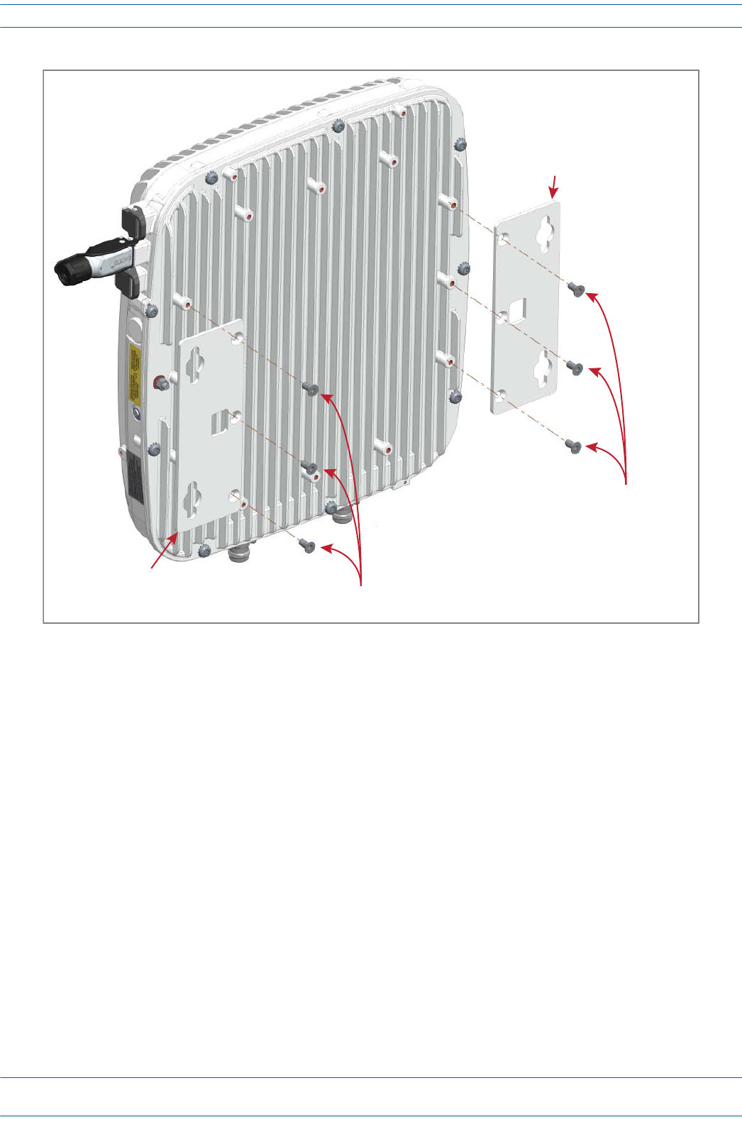
Wall Mount a CAP L Using a Flat Mounting Bracket Kit (PN 7774353-00)
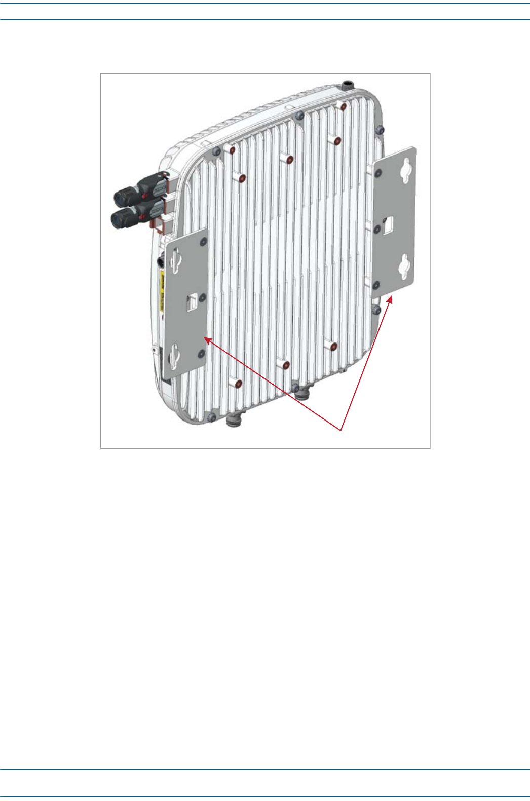
1Followthestepsin"UnpackandInspecttheCAPLandOptionalAccessories”onpage96.Table7-6lists
theFlatMountingBracketKitcomponents.
2Refertoandobserveallcautionslistedin"MountingCautions”onpage95.
3Referto"DeterminetheCAPLMountingSite”onpage90todeterminethemountinglocation,whichmust
beabletosupporttheweightanddimensionsoftheCAPL.
4Referto"MountingOrientation”onpage93todeterminethemountingorientationoftheCAPL.
Always mount the CAP L with the face containing the mounting holes against the mounting surface.
To maintain proper ventilation, keep at least 76 mm (3-inch) clearance around the CAP L.
Do not stack CAP Ls on top of each other.
Table 7-6. Flat Mounting Bracket Kit (PN 7774353-00)
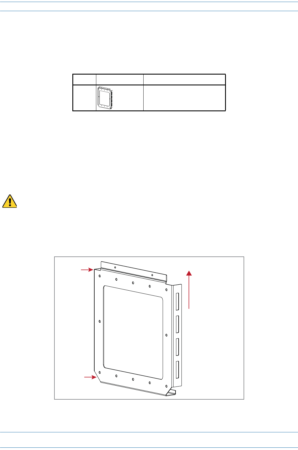
Quantity Part Number Component
2 7725696 Mounting Brackets
6 100901-50 M6-1.0 x 14mm screws
CAP L with Flat Mounng Bracket
(mount vercally)
CAP L with Fan Kit and Flat Mounng Bracket
(mount horizontally)
ION®-E Series Hardware Installation Guide M0201AA
Page 98 © June 2017 CommScope, Inc.
Installing CAP Ls
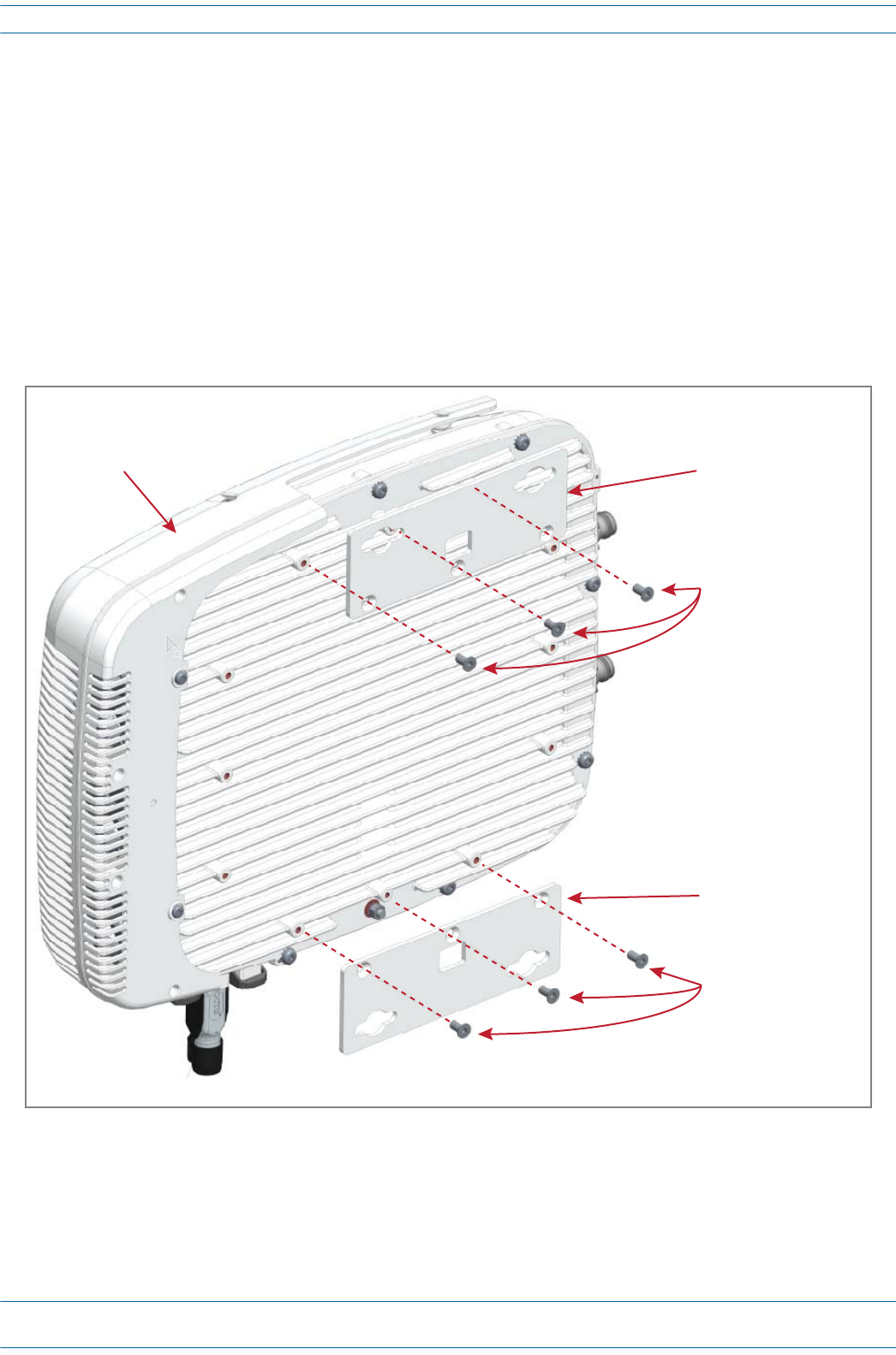
5AttachthetwomountingbracketstothebackoftheCAPLenclosure.
aUsethreeoftheM6-1.0x14mmscrews(PN100901-50)thatcamewiththeFlatMountingBracket
KittoattachtheleftortopmountingbrackettothethreecorrespondinghorizontalorverticalM6-1.0
mountingtapsonthebackoftheCAPLchassis.
bUsethreeoftheM6-1.0x14mmscrewsthatcamewiththeFlatMountingBracketKittoattachthe
rightorbottommountingbrackettothethreecorrespondinghorizontalorverticalM6-1.0mounting
tapsonthebackoftheCAPLchassis.
6Usefour5/16-inchorM8lagscrews(orwhateverscrewtypeisappropriateforthematerialtowhichthe
CAPListomountedon)tomounttheCAPLtothewall.
7Followthestepsin"(Optional)GroundtheCAPL”onpage110ifgroundingisrequiredinyourlocalityor
ifyouprefertogroundtheCAPL.
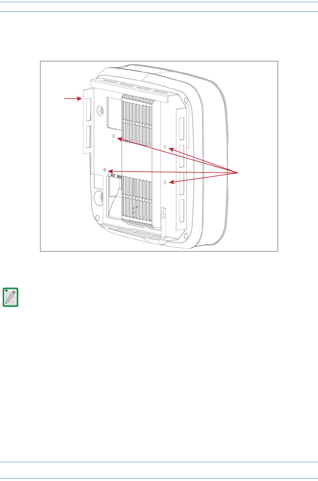
Figure 7-6. CAP L (No Fan Kit) with Flat Mounting Bracket Kit
One Mounng bracket
(PN 7725696)
in vercal posion
Three M6-1.0 x 14mm
screws (PN 100901-50)
One Mounng bracket
(PN 7725696)
in vercal posion
Three M6-1.0 x 14mm
screws (PN 100901-50)
NOTE: Install a CAP L that does not have a Fan Kit vercally.
Fan Kit
M0201AA ION®-E Series Hardware Installation Guide
© June 2017 CommScope, Inc. Page 99
Installing CAP Ls
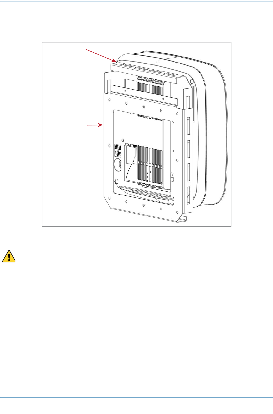
Figure 7-7. CAP L with a Fan Kit and Flat Mounting Bracket Kit
One Mounng bracket
(PN 7725696)
in horizontal posion
Three M6-1.0 x 14mm
screws (PN 100901-50)
One Mounng bracket
(PN 7725696)
in horizontal posion
Three M6-1.0 x 14mm
screws (PN 100901-50)
NOTE: Install a CAP L that
has a Fan Kit horizontally.
ION®-E Series Hardware Installation Guide M0201AA
Page 100 © June 2017 CommScope, Inc.
Installing CAP Ls
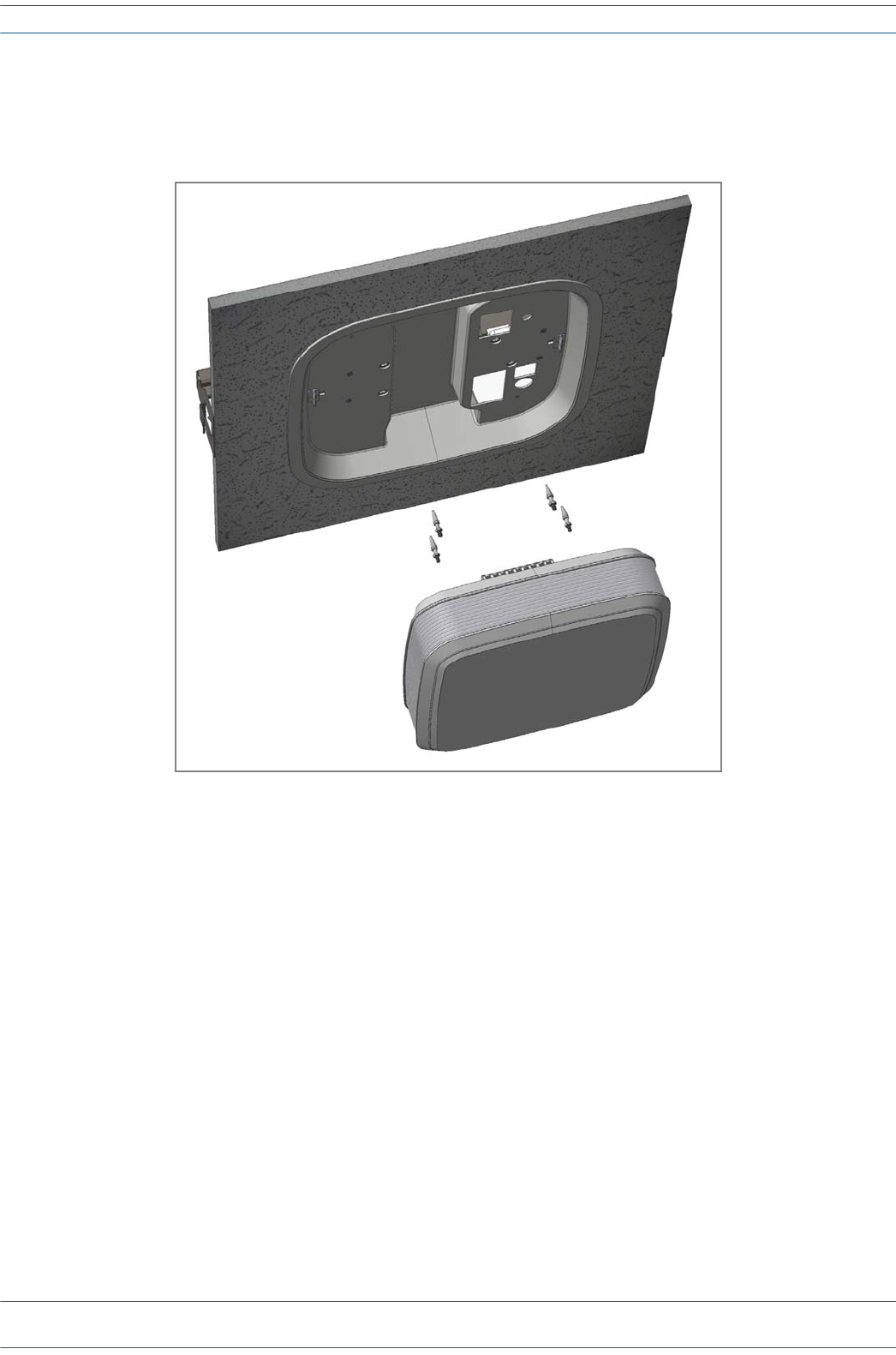
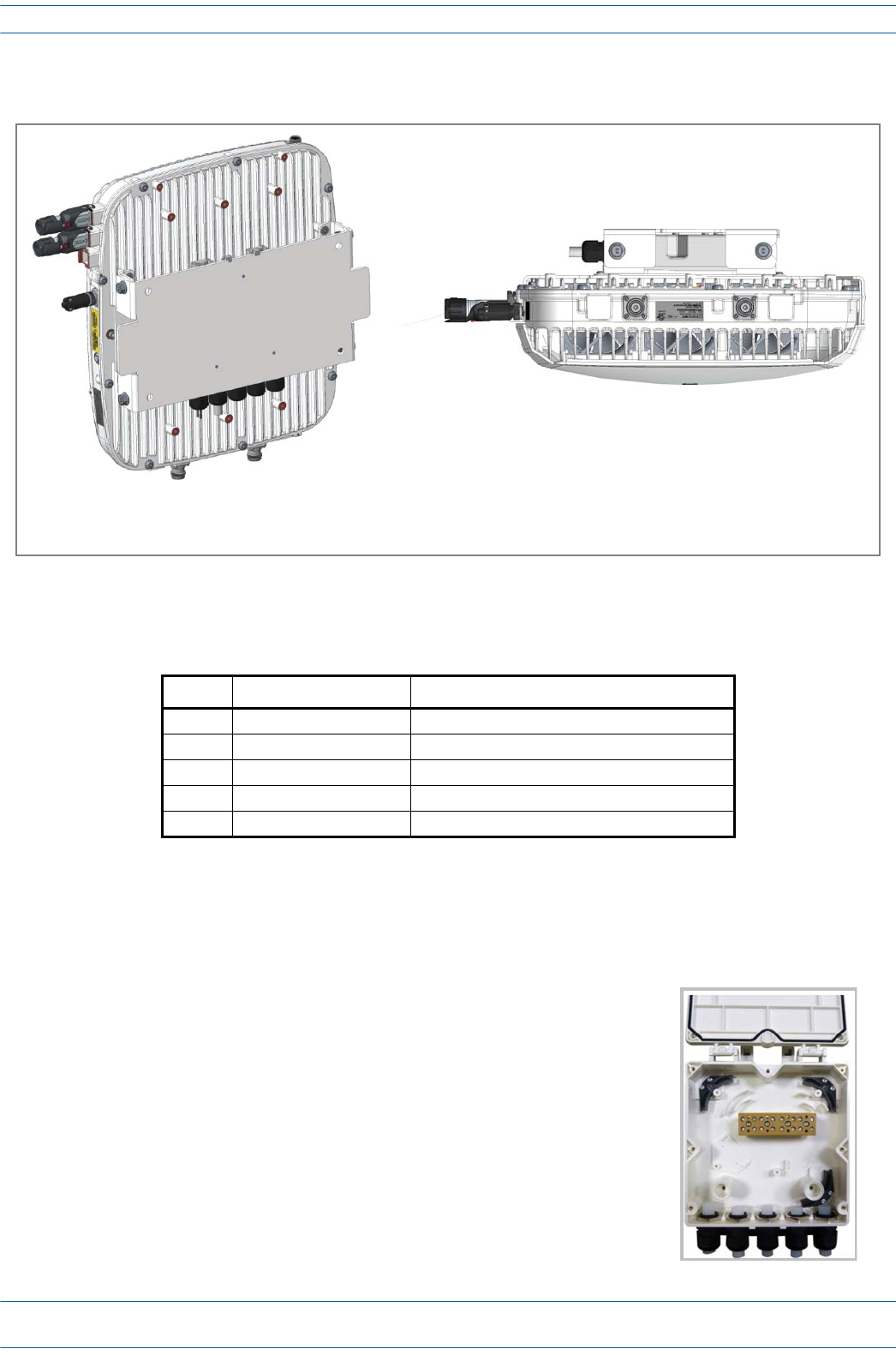
Wall Mount a CAP L Using a Power Supply / Hybrid Fiber Mounting Kit (PN 7774354-00)
1Followthestepsin"UnpackandInspecttheCAPLandOptionalAccessories”onpage96.Table7-7lists
thePowerSupply/HybridFiberMountingKitcomponents.
2Referto"DeterminetheCAPLMountingSite”onpage90todeterminethemountinglocation,whichmust
beabletosupporttheweightanddimensionsoftheCAPL.
3Referto"MountingOrientation”onpage93todeterminethemountingorientationoftheCAPL.
4AssemblethecablesintheHybridFiberSpliceBox(PN7693816-00)
Table 7-7. Hybrid Fiber Mounting Kit (PN 7774354-00)
Quantity Part Number Component
4 100762-1 M8x16 flange-head screws
6 100901-50 M6-1.0 x 14mm screws
1 7771350 Wall Mounting Bracket
2 7771351 Angled Mounting Brackets
1 7693816-00 Hybrid Fiber Splice Box
aOpentheSpliceBoxandremovetheinstallationkitthatisinside.
CAP L with
Power Supply / Hybrid Fiber Mounng Kit
(mount vercally)
CAP L with Fan Kit and
Power Supply / Hybrid Fiber Mounng Kit
(mount horizontally)
M0201AA ION®-E Series Hardware Installation Guide
© June 2017 CommScope, Inc. Page 101
Installing CAP Ls
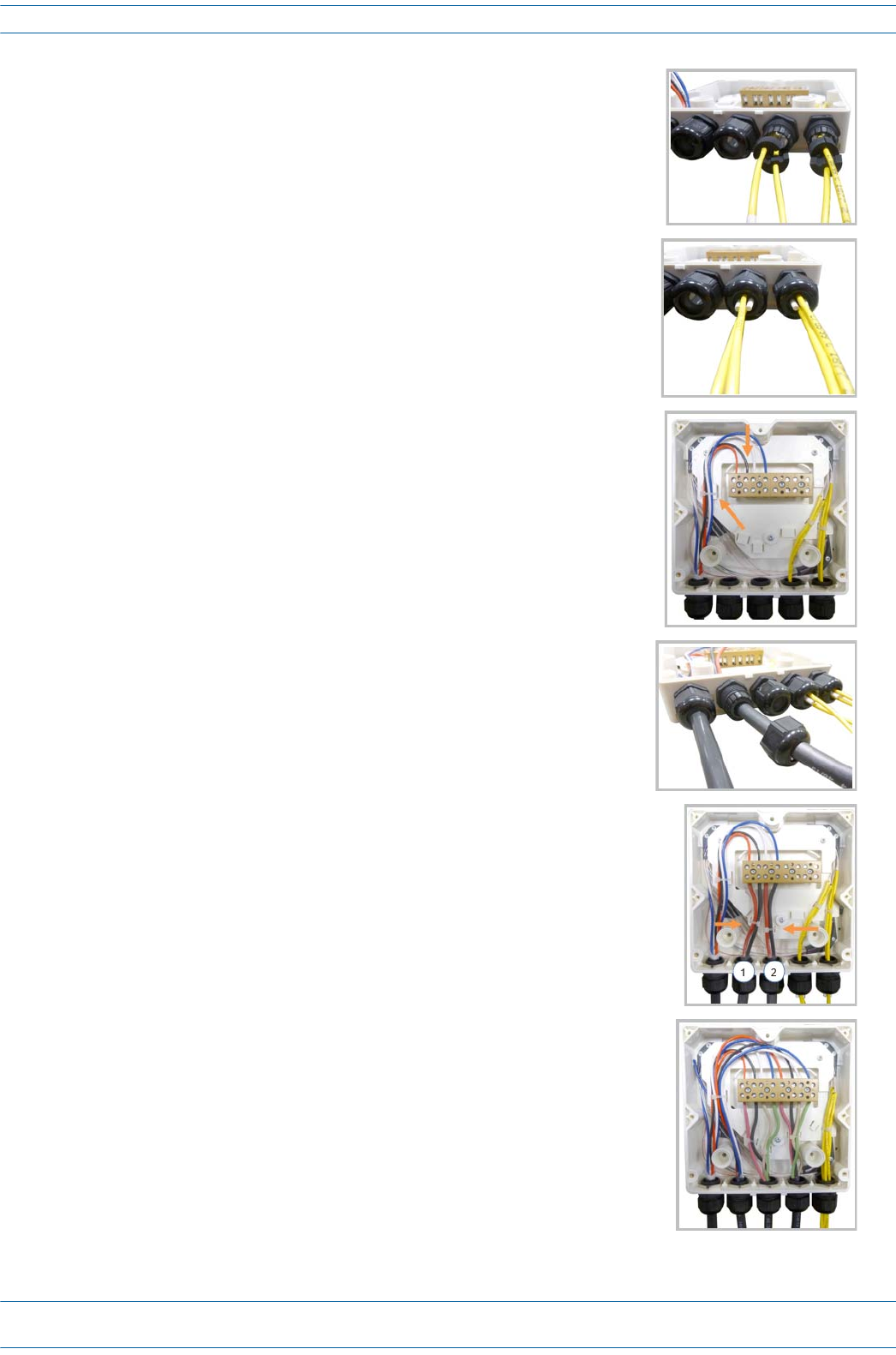
bInserttheSpliceHolder(PN7582294)andfastenitusinga
PTK30x6screw(PN7692771)andoneM4washer
(PN7143057).
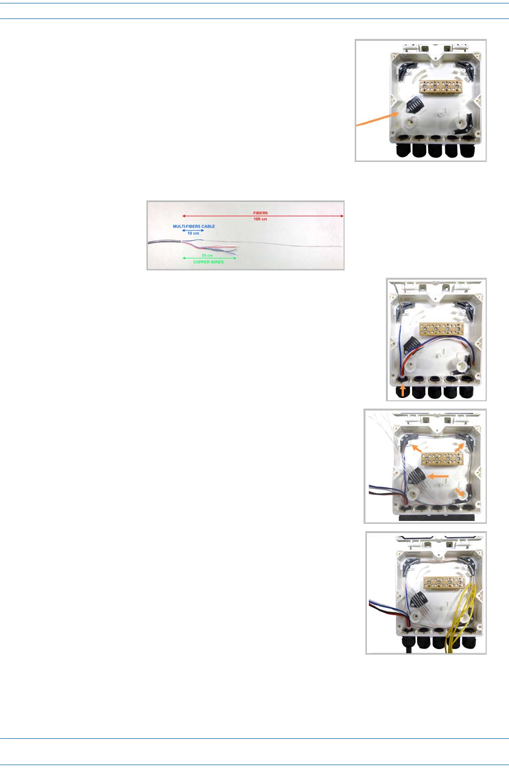
cStriptheinsulationofthecompositecablefor100cmandthefibersfor90cm,andthenshorten
thecoppercablesto25cm.
dInsertthecompositecableinthefirstcableglandandseparate
themulti-fiberscablefromthecopperwires.Itisnecessaryto
removethenuttoperformthisaction.Thecablemustbefed
throughthenutandithastoberetightenedoncefinished.
eBendthesplicedfibersusingthecornerguidesandfixthe
splicestothespliceholder.
fBendtheopticalcablesasshowinthepicturetotheright.
ION®-E Series Hardware Installation Guide M0201AA
Page 102 © June 2017 CommScope, Inc.
Installing CAP Ls
gIfasecondspliceholderisneeded,itcanbeassembledusingthe
M4insulatingwasher(PN7696866)andtwoM4plainwashers
(PN7143057),asshowntotheright.Therequiredscrewisa
PTK30x12(PN7696787).
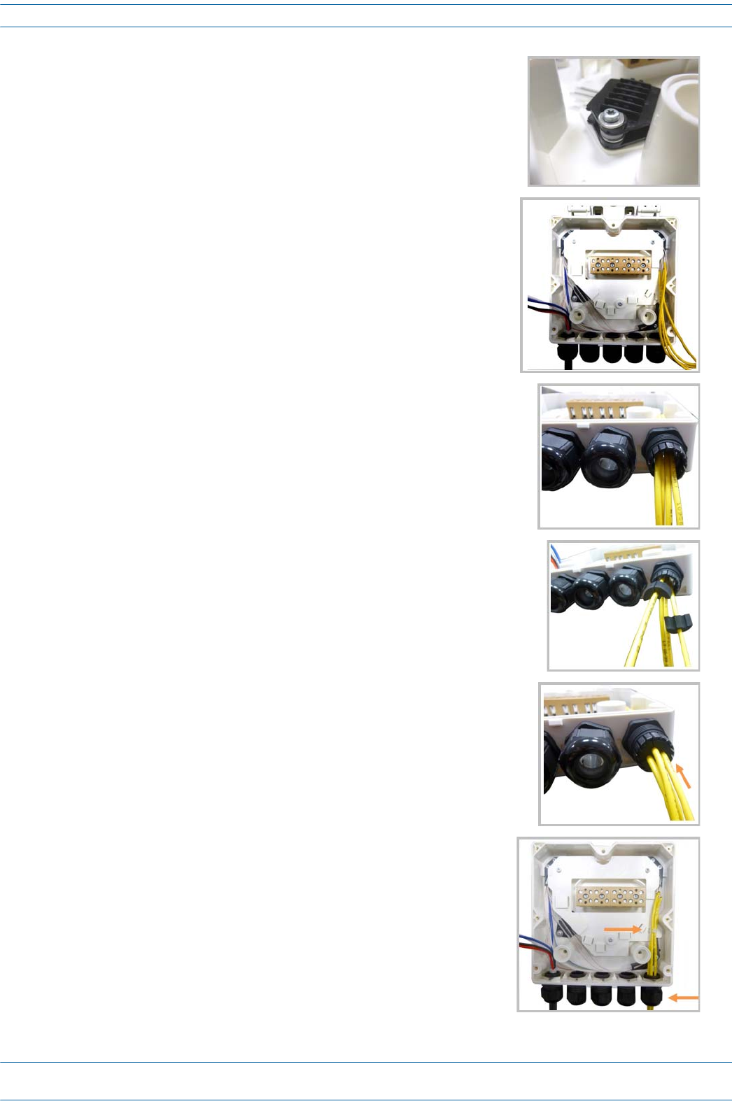
hMounttheinternalsupportSpliceBoxION-URU
(PN7683602-00)usingthreePTK30x6(PN7692771)screws.
iRemovethesealingnutandrubberofthecableglandandinsert
theopticalcables.
jPlaceeachcableintooneofthegroovesofthesealinsert
(PN7682791-00).
kPressthesealinsertintotheclampringopening.
lFixtheopticalcablesinsidetheboxusingonecabletie
(PN7582282)andtightthesealingnut.
M0201AA ION®-E Series Hardware Installation Guide
© June 2017 CommScope, Inc. Page 103
Installing CAP Ls
mItispossibletoseparatetheopticalcablesandusetwodifferent
cableglands.Removethesealingnutandrubberoneachcable
gland.
nCloseallunusedgrooveswiththeplasticcylinders
(PN7157164),nomatterifoneortwocableglandsareused.
oInsertthecopperwiresinthefirstmultipleterminalconnectors.
Seemarkingsontheinternalsupport.Thenfastenthecopper
cablesinsidetheboxusingonecabletie(PN7582282).
pRemovethesealingnutandinserttheRemoteUnitsupplycable
(PN7163674)andtightenthesealingnut.
qConnectthesupplycabletotheterminalstripandfixitinsidethe
boxusingonecabletie(PN7582282).Itispossibletoconnecta
secondsupplycable.
rIncaseofusingremoteunitVdc/100connectthesupplycable
(PN7669706-00)asshownbesides.Refertomarkingsonthe
internalsupport.
ION®-E Series Hardware Installation Guide M0201AA
Page 104 © June 2017 CommScope, Inc.
Installing CAP Ls
5AttachtheHybridFiberSpliceBox(PN7693816-00)totheWallMountingBracket(PN7771350).[Use
what screws? None were shown in the assembly drawings. Or does it clip to the bracket?]
6UsethesixM6-1.0x14mmscrews(PN100901-50)toattachthetwoAngledMountingBrackets
(PN7771351)tothebackoftheCAPLchassis.
RefertooneofthefollowingfiguresforthelocationofthecorrespondingsixM6-1.0mountingtaps:
•CAPL,noFanKit—Figure7-8
•CAPLwithFanKit—Figure7-9onpage105.
7UsethefourM8x16flange-headscrews(PN100762-1)toattachtheassembledHybridFiberSpliceBox
andWallMountingBrackettotheAngledMountingBracketsthatyouattachedtotheCAPLinStep6.
Figure 7-8. CAP L (No Fan Kit) with Power Supply / Hybrid Fiber Mounting Kit
Six M6-1.0 x 14mm screws
One Hybrid
Fiber Splice Box
One Wall Mounng Bracket
Two Angled
Mounng Brackets
Four M8x16 flange-head screws
NOTE: Install a CAP L that does not
have a Fan Kit vercally.