Andrew Wireless System CAPL17E23 ION-E Remote Unit for cellular systems User Manual M0201AAA
Andrew Wireless System ION-E Remote Unit for cellular systems M0201AAA
Contents
- 1. users manual part 1
- 2. users manual part 2
- 3. users manual part 3
- 4. installation manual
users manual part 3
M0201AA ION®-E Series Hardware Installation Guide
© June 2017 CommScope, Inc. Page 105
Installing CAP Ls
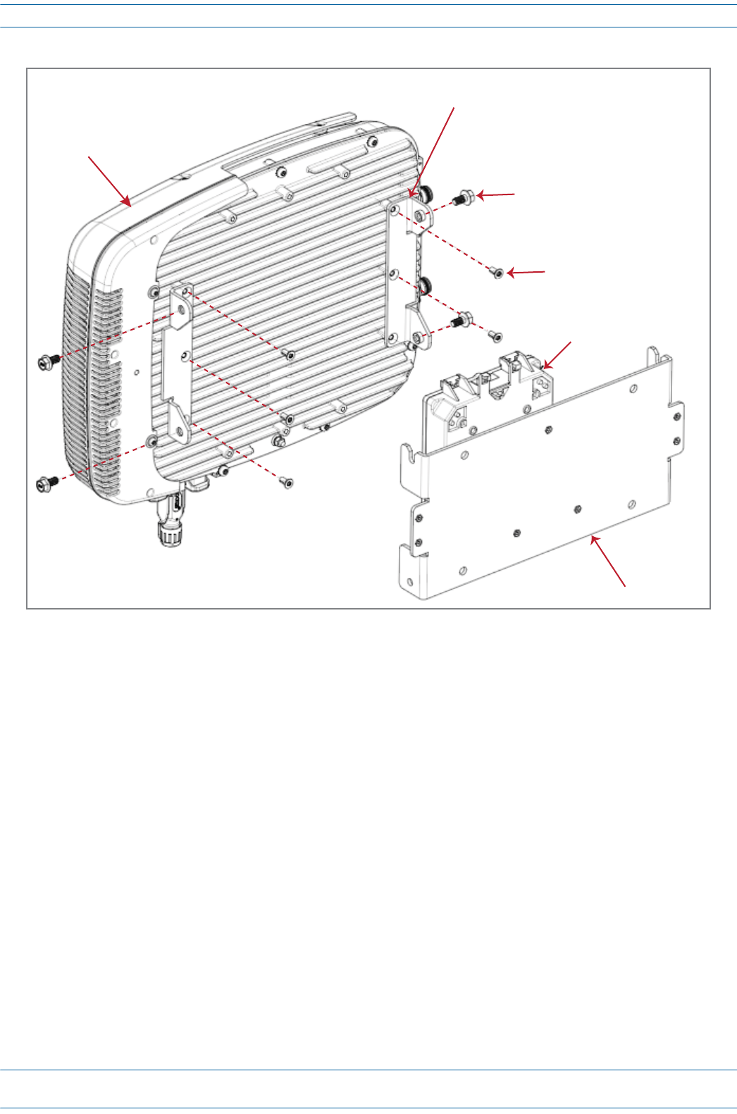
Figure 7-9. CAP L with Fan Kit and with Power Supply / Hybrid Fiber Mounting Kit
8Followthestepsin"(Optional)GroundtheCAPL”onpage110ifgroundingisrequiredinyourlocalityor
ifyouprefertogroundtheCAPL.
Two Angled
Mounng Brackets
Four M8x16 flange-head screws
Six M6-1.0 x 14mm screws
One Hybrid
Fiber Splice Box
One Wall Mounng Bracket
NOTE: Install a CAP L that has a Fan Kit horizontally.
Fan Kit
ION®-E Series Hardware Installation Guide M0201AA
Page 106 © June 2017 CommScope, Inc.
Installing CAP Ls
Wall Mount a CAP L Using a 240W AC/DC Power Supply Kit (PN 7775087-00)
Figure 7-10. CAP L with a Power Supply / Hybrid Fiber Mounting Kit
1Refertoandobserveallcautionslistedin"MountingCautions”onpage95.
2Referto"DeterminetheCAPLMountingSite”onpage90todeterminethemountinglocation,whichmust
beabletosupporttheweightanddimensionsoftheCAPL.
3Referto"MountingOrientation”onpage93todeterminethemountingorientationoftheCAPL.
4Followthestepsin"UnpackandInspecttheCAPLandOptionalAccessories”onpage96.Table7-8lists
the240WAC/DCPowerSupplyKitcomponents.
Table 7-8. 240W AC/DC Power Supply Kit Components (PN 7775087-00)
Quantity Part Number Component
1 7771350 Wall Mounting Bracket
2 7771351 Angled Mounting Brackets
1 7774061 Local Power Jumper Cable Assembly
1 7774356 48V, 240W AC/DC Power Supply Unit with Junction Box
4 100762-1 M8x16 flange-head screws
6 100901-50 M6-1.0 x 14mm screws
4 100907-126
Local Power Jumper cable
OAP Close-Coupled Power Supply Mounng Kit
OAP Vdc Power connector
48V, 240W AC/DC Power Supply
Unit with Juncon Box
M0201AA ION®-E Series Hardware Installation Guide
© June 2017 CommScope, Inc. Page 107
Installing CAP Ls
5Assemblethe240WAC/DCPowerSupplyKit.
aAttachtheLocalPowerJumperCableAssembly(PN7774061)totheAC/DCPowerSupplyJunction
Box(PN7774356).
bUsethefourscrews(PN100907-126)toattachthe240WAC/DCPowerSupplyassemblytotheWall
MountingBracket(PN7771350).
6UsethesixM6-1.0x14mmscrews(PN100901-50)toattachthetwoAngledMountingBrackets
(PN7771351)tothebackoftheCAPLchassis.
RefertooneofthefollowingfiguresforthelocationofthecorrespondingsixM6-1.0mountingtaps:
•CAPL,noFanKit—Figure7-11
•CAPLwithFanKit—Figure7-12onpage108.
7UsethefourM8x16flange-headscrews(PN100762-1)toattachtheassembled240WAC/DCPower
SupplyKitandWallMountingBrackettotheAngledMountingBracketsthatyouattachedtotheCAPLin
Step6.
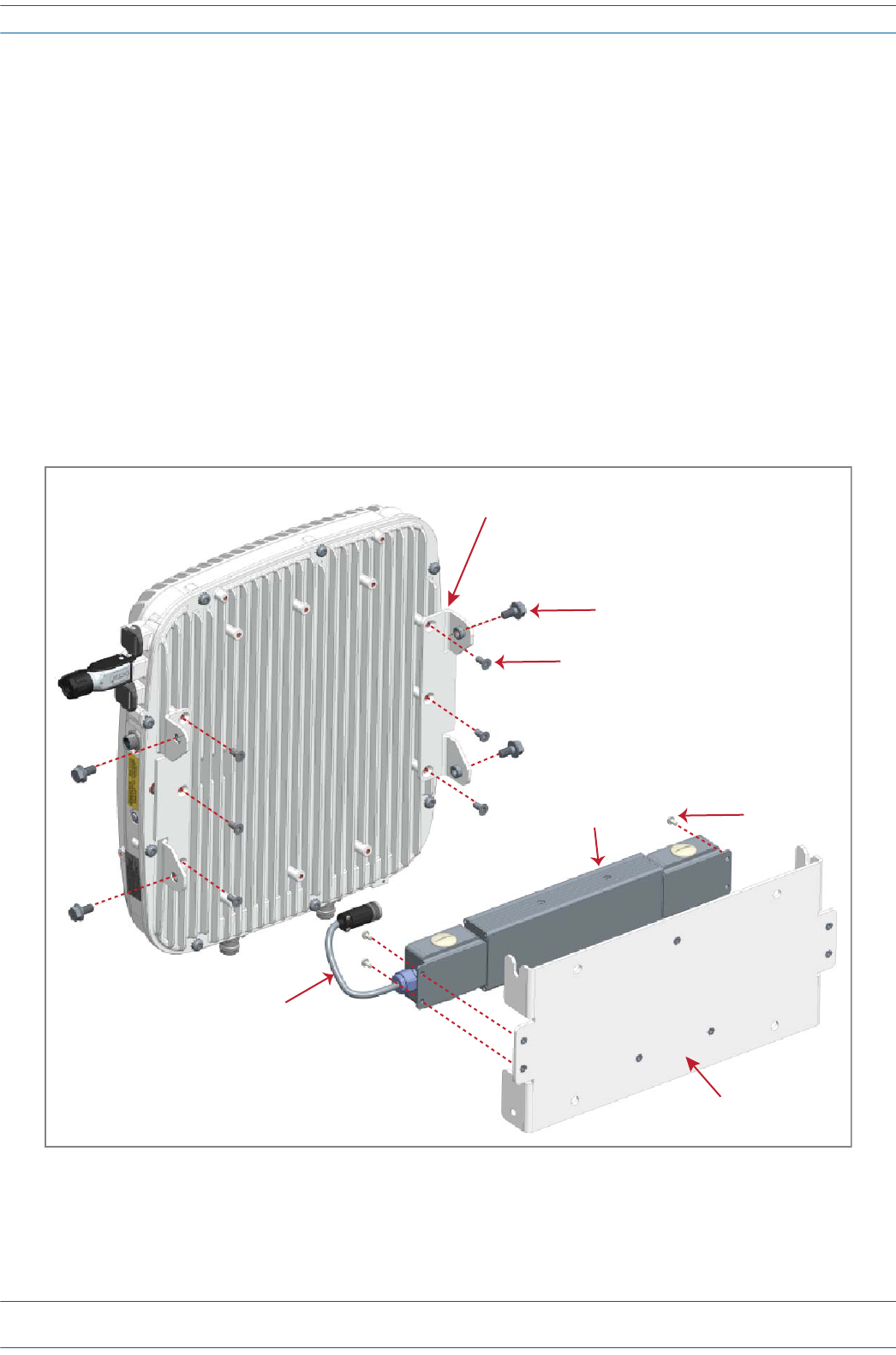
Figure 7-11. CAP L (No Fan Kit) with 240W AC/DC Power Supply Kit
Two Angled
Mounng Brackets
Four M8x16 flange-head screws
Six M6-1.0 x 14mm screws
Four screws
One Wall
Mounng Bracket
48V, 240W AC/DC
Power Supply Unit
with Juncon Box
Local Power
Jumper Cable
Assembly
ION®-E Series Hardware Installation Guide M0201AA
Page 108 © June 2017 CommScope, Inc.
Installing CAP Ls
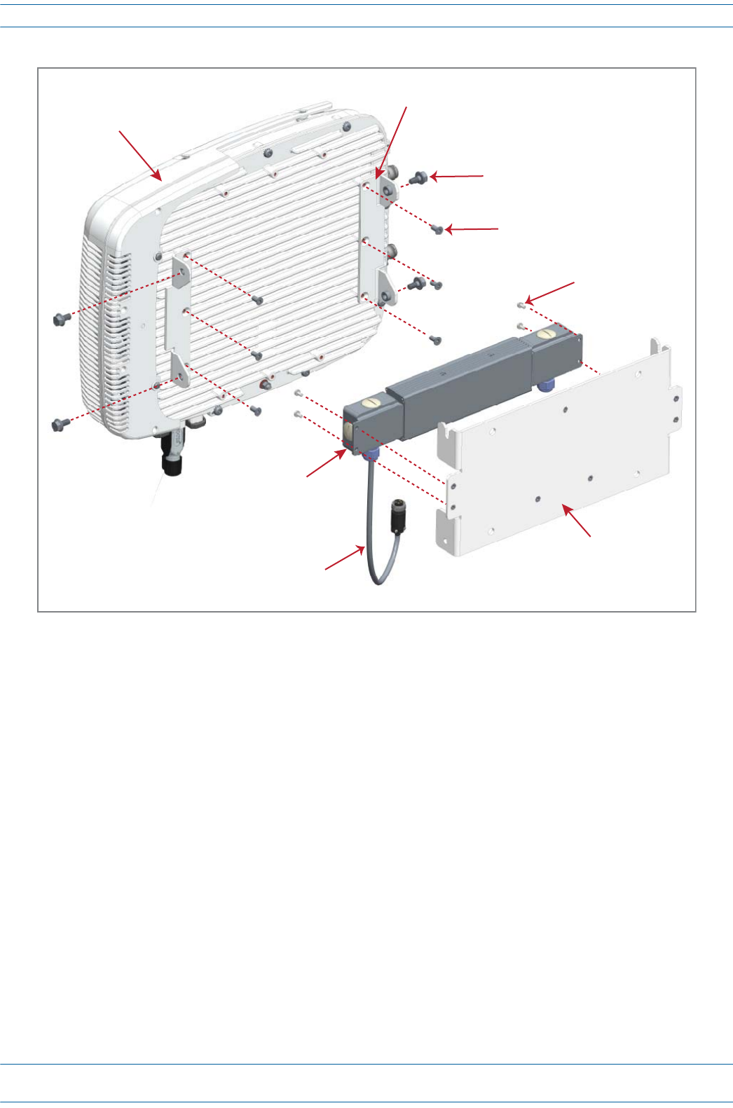
Figure 7-12. CAP L with Fan Kit and with 240W AC/DC Power Supply Kit
8Followthestepsin"(Optional)GroundtheCAPL”onpage110ifgroundingisrequiredinyourlocalityor
ifyouprefertogroundtheCAPL.
Two Angled
Mounng Brackets
Four M8x16 flange-head screws
Six M6-1.0 x 14mm screws
Four screws
One Wall
Mounng Bracket
48V, 240W AC/DC
Power Supply Unit
with Juncon Box
Local Power
Jumper Cable
Assembly
Fan Kit
M0201AA ION®-E Series Hardware Installation Guide
© June 2017 CommScope, Inc. Page 109
Installing CAP Ls
Ceiling Mount a CAP L
1Followthestepsin"UnpackandInspecttheCAPLandOptionalAccessories”onpage96.
2Refertoandobserveallcautionslistedin"MountingCautions”onpage95.
3Referto"DeterminetheCAPLMountingSite”onpage90todeterminethemountinglocation,whichmust
beabletosupporttheweightanddimensionsoftheCAPL.
4Refertothefollowinggraphicforspacingrequirements.
5Followthestepsinoneofthefollowingsectionsthatapplytosecuringthedesiredmountingbracketto
theCAPL:
•"WallMountaCAPLUsingaFlatMountingBracketKit(PN7774353-00)”onpage97
•"WallMountaCAPLUsingaPowerSupply/HybridFiberMountingKit(PN7774354-00)”on
page100
•"WallMountaCAPLUsinga240WAC/DCPowerSupplyKit(PN7775087-00)”onpage106
6Usefour5/16-inchorM8lagscrews(orwhateverscrewtypeisappropriateforthematerialtowhichthe
CAPListomountedon)tomounttheCAPLtotheceiling.
7Followthestepsin"(Optional)GroundtheCAPL”onpage110ifgroundingisrequiredinyourlocalityor
ifyouprefertogroundtheCAPL.
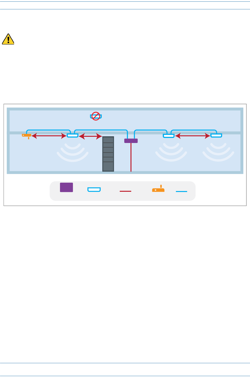
Only a CAP L with a Fan Kit can be ceiling mounted. Do not ceiling mount a CAP L that does not have a Fan
Kit attached to it.
WiFi
3m min
3m min
Install below ceiling grid only
2m min
Collocated UAPs (MIMO)
Metal Cabinet
CAN/TEN CAP MM/SM Fiber WiFi CAT 6A
ION®-E Series Hardware Installation Guide M0201AA
Page 110 © June 2017 CommScope, Inc.
Installing CAP Ls
(Optional) Ground the CAP L
FollowthestepsbelowtogroundtheOPAonlyifgroundingisrequiredinyourlocalityoriftheinstallation
plansrequiretheCAPLbegrounded.ThedifferentCAPLinstallationprocedureswilltellyouwhentoground
theCAPL.
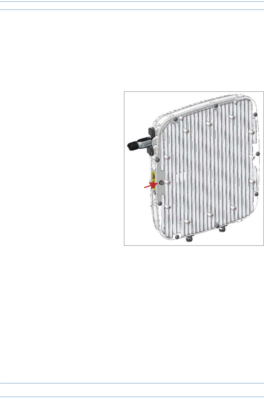
NOTE: The CAP L is equipped with a green grounding screw located on the back of the unit; however,
grounding is not necessary. CAP Ls are classified as low-voltage devices and do not have internal
power supplies. CommScope recommends checking your local and national electrical codes to
determine if grounding is a requirement.
1Obtainalengthof#18AWG(1.00mm)
insulatedstrandedcopperwireforuseas
achassis-groundingwire.
2Terminateoneendofthewirewitharing
terminal.
3Locatethechassis-groundstudattherear
oftheCAPLenclosure.
4RemovetheKepsnutfromthe
chassis-groundstud.
5Attachtheringendofthewiretothe
chassisgroundstud,asshownbelow.
6UsetheKepsnutremovedinStep4to
securethegroundwiretothe
chassis-groundstud.
7Routethefreeendofthechassis
groundingwiretoanapproved(perlocal
codeorpractice)earthgroundsource.
Ground
stud
M0201AA ION®-E Series Hardware Installation Guide
© June 2017 CommScope, Inc. Page 111
Installing CAP Ls
Connect the CAP L Cables
ThetypeofcablesusedandhowtheCAPLconnectsintothesystemisdependentontheCAPLtype.Follow
thecablinginstructionsthatapplytotheunittypethatyouareinstalling.
•"CableaCAPLwithanOpticalFiberInterface”onpage111
•"CableaCAPLwithaCopperInterfaceandPoweroverCategory6ACable”onpage114
•"CableaCAPLwithaCopperInterfaceandPoweroverEthernet”onpage116
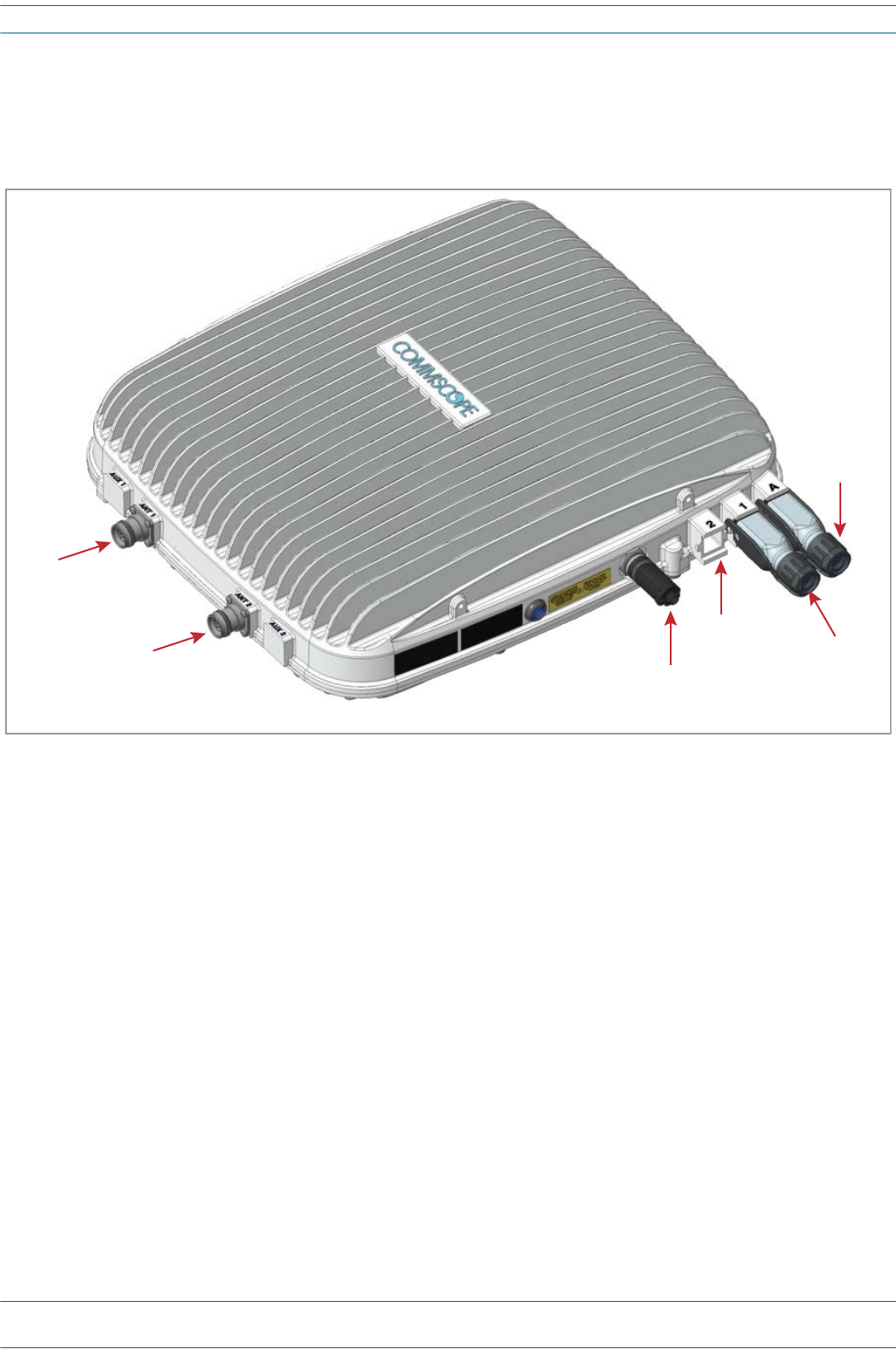
Cable a CAP L with an Optical Fiber Interface
Figure7-13identifiestheconnectorsonaCAPLwithanOpticalFiberInterface;correspondingcablesand
connectorsareshown.
CAUTION! Do not remove caps from any of the connectors until instructed to do so.
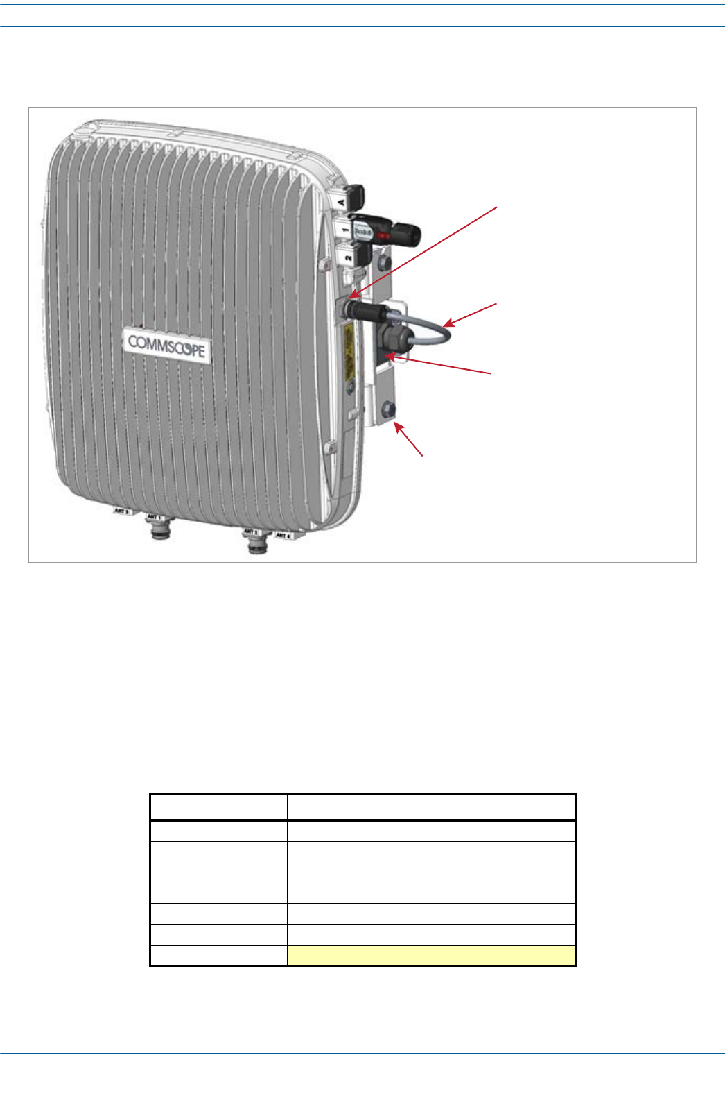
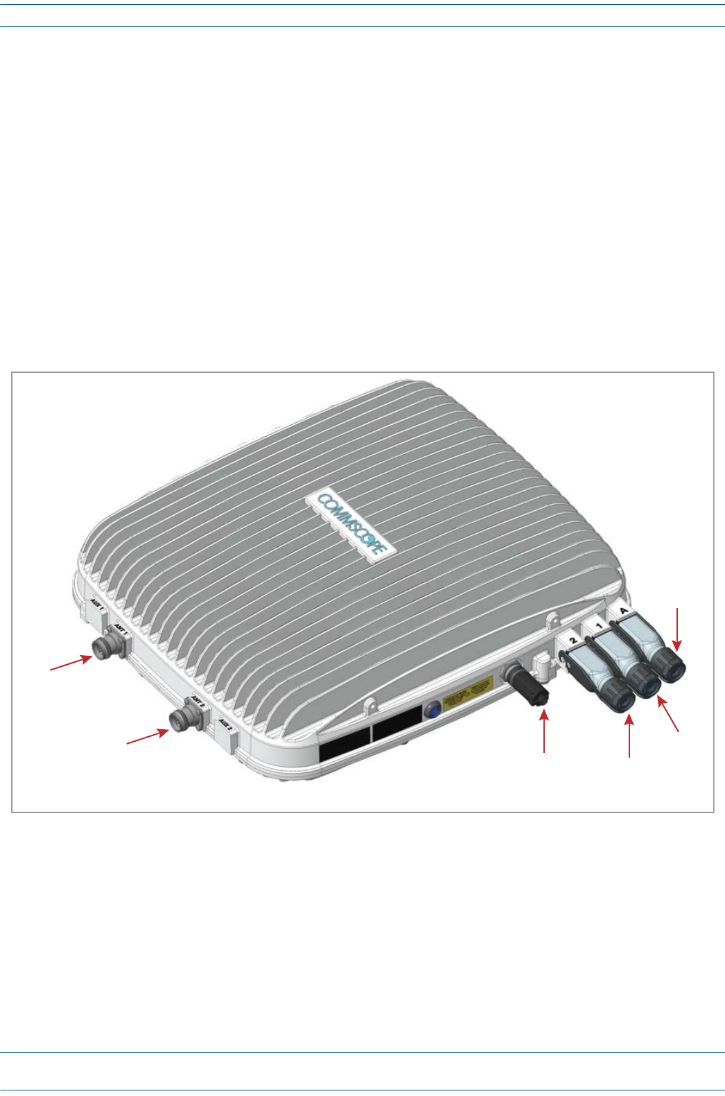
Figure 7-13. Connectors on a CAP L with an Optical Fiber Interface
ANT
1
ANT
2Vdc
Power
connector
Opcal
Port
2
Opcal
Port
1
Auxiliary
port
ION®-E Series Hardware Installation Guide M0201AA
Page 112 © June 2017 CommScope, Inc.
Installing CAP Ls
1ConnecttheCAPLANT1and/orANT2connectortoapassiveRFantenna.
aObtain50ΩcoaxialcablesthatareofsufficientlengthtoreachfromtheCAPLtothepassiveantenna.
Theendofthe50ΩcoaxialcablethatwillconnecttotheANTconnectorcanbeeitherapush-pull
connectororathreadedconnector.
bInstallthepassiveantennasaccordingtothemanufacturer’sinstallationinstructions.Ifconnecting
bothANTconnectors,youwillconnecttheCAPLtoeithertwoseparateexternalpassiveantennasor
totwoportsonacross-polarizeddualantenna.EachconnectorsupportstwoRFbands(see
Table7-9).
cIs there a dust cap on ANT 1/2 that needs to be removed?
dConnectthepassivemulti-bandantennatotheANT1orANT2connectorusingcoaxialcablewiththe
leastamountoflosspossible.
•Ifthe50Ωcoaxialcablehasapush-pullconnector,makesurethecableisseatedfirmlyintheANT
1orANT2connector.
•Ifthe50Ωcoaxialcablehasathreadedconnector,torquetheconnector5N-m(3.69ft-lb).Donot
over-tightentheconnector.
eConnecttheotherendofthe50ΩcoaxialcabletothepassiveantennainstalledinStepbonpage112.
2Ifnecessary,repeatStep1onpage112toconnecta50ΩcoaxialcabletotheotherANTconnector.
3ConnecttheOpticalPort1connectorasappropriateforthisinstallation.
aObtainSingleModeFiber(SMF)orMultiModeFiber(MMF)thatisofsufficientlengthtoreachfrom
theCAPLtotheION-ECAN/TEN.[when would you use SM vs. MM?]
bRemovethedustcapfromtheOpticalPort1connectorandtheconnectorsontheSMorMMfiber.
cFollowthelocalcleaningtechniquetocleanOpticalPort1.
dCleantheconnectorsontheSMForMMFfollowingthefibersupplier’srecommendations.
eConnectoneendoftheSMForMMFtotheOpticalPort1connectorandtheotherendto[to what
EXACTLY does the other end of the cable connect on the CAN/TEN or junction box?]
UNRESOLVED: If Opt 1 can connect to the ION-E CAN/TEN or to a local Hybrid Fiber Junction Box to provide
the main signal and power interface, when does optical transport occur over Single Mode
(SM) or Multi Mode (MM) fiber? We need to identify what type of cable to use, and does
the customer supply the cable or does it ship with the CAP L?
Table 7-9. Mapping Frequency Bands to Antennas
Frequency Band Band Combination Antenna Port
AWS1700 / LTE2300 17E and 23 1
AWS1700 / LTE2300 17E and 23 2
GSM1800 / UMTS2100 / LTE2600 18 and 26 1
GSM1800 / UMTS2100 / LTE2600 21 and 26 2
AWS1700 / PCS1900 17E and 19 1
AWS1700 / PCS1900 17E and 19 2

M0201AA ION®-E Series Hardware Installation Guide
© June 2017 CommScope, Inc. Page 113
Installing CAP Ls
4Ifappropriateforthisinstallation,connecttheOpticalPort2connector.
aRaisetheleverontheEMI/IP67caponOpticalPort2connectorandremovethecap.
bRemovethecapsfromtheconnectorsontheSMorMMfiber.
cFollowthelocalcleaningtechniquetocleanOpticalPort2.
dCleantheconnectorsontheSMForMMFfollowingthefibersupplier’srecommendations.
eConnectoneendoftheSMForMMFtotheOpticalPort2connectorandtheotherendto[to what
EXACTLY does the other end of the cable connect on the CAN/TEN or junction box?]
UNRESOLVED: If Opt 2 can connect to a local Hybrid Fiber Junction Box or a cascaded CAP L to provide the
main signal and power interface, when does optical transport occur over Single Mode (SM)
or Multi Mode (MM) fiber? We need to identify what type of cable to use, and does the
customer supply the cable or does it ship with the CAP L?
5ConnecttheAuxiliaryconnectorasappropriateforthisinstallation.
aRaisetheleverontheEMI/IP67capontheAuxiliaryconnectorandremovethecap.
UNRESOLVED: AUX port can connect to external Ethernet devices such as WiFi and IP cameras. What type
of cable do you use for each? Cabling is via the appropriate CAT cable for the protocol; this
model supports an 1000 BASE-T and 802.3at Class 3 PoE (minimum) Ethernet connection.
We need to identify what type of cable to use, and does the customer supply the cable or
does it ship with the CAP L?
UNRESOLVED: Verify that maximum attached cable length is 3 meters (9.8 feet).
UNRESOLVED: To what does the other end of the cable connect to on external Ethernet devices such as WiFi
and IP cameras?
6ConnecttheVdcPowerconnectorasappropriateforthisinstallation.
aFindtheLocalPowerJumperCableAssemblythatwasshippedwiththemountingkit.
bConnectthefour-pinconnectortotheVdcPowerconnectorontheCAPL.
UNRESOLVED: Spec stated that this model can connect to a local or external power supply, or to a Hybrid
Fiber Junction Box, is the power cable the same for all three options? For each option, to
what does the power cable connect?
TheCAPLispoweredonassoonasyouconnecttheLocalPowerJumperCableAssemblytoapower
source;see"PoweringaCAPL”onpage82.
ION®-E Series Hardware Installation Guide M0201AA
Page 114 © June 2017 CommScope, Inc.
Installing CAP Ls
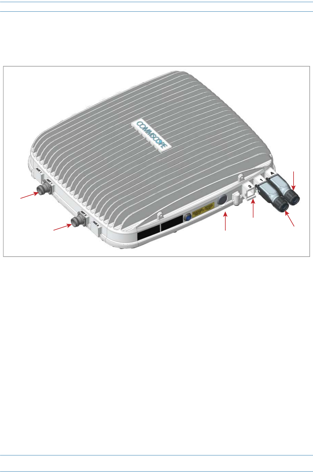
Cable a CAP L with a Copper Interface and Power over Category 6A Cable
Figure7-14identifiestheconnectorsonaCAPLwithaCopperInterfacethatispoweredoverCategory6A
cable;correspondingcablesandconnectorsareshown.
Figure 7-14. Connectors on a CAP L with a Copper Interface Powered over Category 6A Cable
1ConnecttheCAPLANT1and/orANT2connectortoapassiveRFantenna.
aObtain50ΩcoaxialcablesthatareofsufficientlengthtoreachfromtheCAPLtothepassiveantenna.
Theendofthe50ΩcoaxialcablethatwillconnecttotheANTconnectorcanbeeitherapush-pull
connectororathreadedconnector.
bInstallthepassiveantennasaccordingtothemanufacturer’sinstallationinstructions.Ifconnecting
bothANTconnectors,youwillconnecttheCAPLtoeithertwoseparateexternalpassiveantennasor
totwoportsonacross-polarizeddualantenna.EachconnectorsupportstwoRFbands(seeTable7-2
onpage77).
cIs there a dust cap on ANT 1/2 that needs to be removed?
dConnectthepassivemulti-bandantennatotheANT1orANT2connectorusingcoaxialcablewiththe
leastamountoflosspossible.
•Ifthe50Ωcoaxialcablehasapush-pullconnector,makesurethecableisseatedfirmlyintheANT
1orANT2connector.
•Ifthe50Ωcoaxialcablehasathreadedconnector,torquetheconnector5N-m(3.69ft-lb).Donot
over-tightentheconnector.
eConnecttheotherendofthe50ΩcoaxialcabletothepassiveantennainstalledinStepbonpage114.
2Ifnecessary,repeatStep1onpage114toconnecta50ΩcoaxialcabletotheotherANTconnector.
ANT
1
ANT
2Vdc
Power
connector
Opcal
Port
2
Opcal
Port
1
Auxiliary
port

M0201AA ION®-E Series Hardware Installation Guide
© June 2017 CommScope, Inc. Page 115
Installing CAP Ls
3ConnecttheOpticalPort1connectorasappropriateforthisinstallation.
aObtainSingleModeFiber(SMF)orMultiModeFiber(MMF)thatisofsufficientlengthtoreachfrom
theCAPLtotheION-ECAN/TEN.[when would you use SM vs. MM?]
bRemovethedustcapfromtheOpticalPort1connectorandtheconnectorsontheSMorMMfiber.
cFollowthelocalcleaningtechniquetocleanOpticalPort1.
dCleantheconnectorsontheSMForMMFfollowingthefibersupplier’srecommendations.
eConnectoneendoftheSMForMMFtotheOpticalPort1connectorandtheotherendto[to what
EXACTLY does the other end of the cable connect on the CAN/TEN or junction box?]
UNRESOLVED: Opt 1 connects to the ION-E CAN/TEN to provide the main signal and power interface. We
need to identify what type of cable to use, and does the customer supply the cable or does
it ship with the CAP L?
NOTE: The Optical Port 2 connector is plugged as it is not used in this configuration.
4ConnecttheAuxiliaryconnectorasappropriateforthisinstallation.
aRaisetheleverontheEMI/IP67capontheAuxiliaryconnectorandremovethecap.
UNRESOLVED: The AUX port provides a cascade connection to additional local power or CAP L, or provides
a connection to external Ethernet devices such as WiFi and IP cameras. Spec stated that
cabling is via the appropriate CAT cable for installed unit protocol—what cable type(s) are
supported for each unit type to which it can connect?
UNRESOLVED: Verify that maximum attached cable length is 3 meters (9.8 feet).
UNRESOLVED: To what does the other end of the cable connect to on external Ethernet devices such as WiFi
and IP cameras?
5ConnecttheVdcPowerconnectorasappropriateforthisinstallation.
aFindtheLocalPowerJumperCableAssemblythatwasshippedwiththemountingkit.
bConnectthefour-pinconnectortotheVdcPowerconnectorontheCAPL.
TheCAPLispoweredonassoonasyouconnecttheLocalPowerJumperCableAssemblytoapower
source;see"PoweringaCAPL”onpage82.
UNRESOLVED: Spec stated that this model can connect to a local or external power supply, for each option,
to what does the power cable connect?
ION®-E Series Hardware Installation Guide M0201AA
Page 116 © June 2017 CommScope, Inc.
Installing CAP Ls
Cable a CAP L with a Copper Interface and Power over Ethernet
Figure7-15identifiestheconnectorsonaCAPLwithanOpticalFiberInterface;correspondingcablesand
connectorsareshown.
Figure 7-15. Connectors on a CAP L with a Copper Interface
1ConnecttheCAPLANT1and/orANT2connectortoapassiveRFantenna.
aObtain50ΩcoaxialcablesthatareofsufficientlengthtoreachfromtheCAPLtothepassiveantenna.
Theendofthe50ΩcoaxialcablethatwillconnecttotheANTconnectorcanbeeitherapush-pull
connectororathreadedconnector.
bInstallthepassiveantennasaccordingtothemanufacturer’sinstallationinstructions.Ifconnecting
bothANTconnectors,youwillconnecttheCAPLtoeithertwoseparateexternalpassiveantennasor
totwoportsonacross-polarizeddualantenna.EachconnectorsupportstwoRFbands(seeTable7-2
onpage77).
cIs there a dust cap on ANT 1/2 that needs to be removed?
dConnectthepassivemulti-bandantennatotheANT1orANT2connectorusingcoaxialcablewiththe
leastamountoflosspossible.
•Ifthe50Ωcoaxialcablehasapush-pullconnector,makesurethecableisseatedfirmlyintheANT
1orANT2connector.
•Ifthe50Ωcoaxialcablehasathreadedconnector,torquetheconnector5N-m(3.69ft-lb).Donot
over-tightentheconnector.
eConnecttheotherendofthe50ΩcoaxialcabletothepassiveantennainstalledinStepbonpage116.
2Ifnecessary,repeatStep1onpage116toconnecta50ΩcoaxialcabletotheotherANTconnector.
ANT
1
ANT
2Vdc
Power
connector
Opcal
Port
2
Opcal
Port
1
Auxiliary
port

M0201AA ION®-E Series Hardware Installation Guide
© June 2017 CommScope, Inc. Page 117
Installing CAP Ls
NOTE: The Power connector and the Optical Port 2 connector are plugged as they are not used in this
configuration.
3UseCAT6AcabletoconnecttheOpticalPort1connectortothePoE.
UNRESOLVED: Not really sure what “to the PoE” means.
UNRESOLVED: To what does the other end of the CAT6A cable connect?
4ConnecttheAuxiliaryconnectorasappropriateforthisinstallation.
UNRESOLVED: Is the AUX connector capped during shipment? If yes, state to remove dust cap? If tool
required, need to know what that tool is.
UNRESOLVED: The AUX port provides a connection to external Ethernet devices such as WiFi and IP
cameras. Spec stated that cabling is via the appropriate CAT cable for installed unit
protocol—what cable type(s) are supported for each unit type to which it can connect?
UNRESOLVED: Verify that maximum attached cable length is 3 meters (9.8 feet).
UNRESOLVED: To what does the other end of the cable connect to on external Ethernet devices such as WiFi
and IP cameras?

ION®-E Series Hardware Installation Guide M0201AA
Page 118 © June 2017 CommScope, Inc.
Cascading CAP Ls
CASCADING CAP LS
AsecondCAPLcanbecascadedfromaprimaryCAPL(theCAPLconnecteddirectlytotheCAN/TEN).
LimitationsforcascadedCAPLsarelistedbelow.
•TherecanbeonlytwoCAPLsinacascade.
•Thecascadedunitmustusethesametransporttype(CopperorOptical).
•ThecascadedCAPLmustgetitspowerthroughtheDCconnector(eitherfromalocalsupplyorhybrid
fiber);powerovertheCATcabletothecascadedunitisnotsupported.
•UseoftheAUXportsinacascadedsystemislimitedasfollows:
–ForCopper,useonlytheAUXportonthecascadedCAPL.
–ForOptical,useonlyoneoftheAUXports,whichcanbeoneithertheprimaryorcascadedCAPL.
•Thetotal320MHzRFbandwidthissharedbetweenthetwocascadedunits,butcanbesharedunevenly;
thatis,withmorebandwidthgoingtoeithertheprimaryorcascadedCAPL.
•AftertheprimaryCAPLpowersup,thesecondaryCAPLwillbediscoveredandpoweruponitsown;for
informationonhowaCAPLpowersup,see"PoweringaCAPL”onpage82.
M0201AA ION®-E Series Hardware Installation Guide
© June 2017 CommScope, Inc. Page 119
CAP L Maintenance
CAP L MAINTENANCE
ThefollowingsectionstellyouhowtoremoveaCAPLfrommountingbrackets,andprovidespreventative
maintenance.
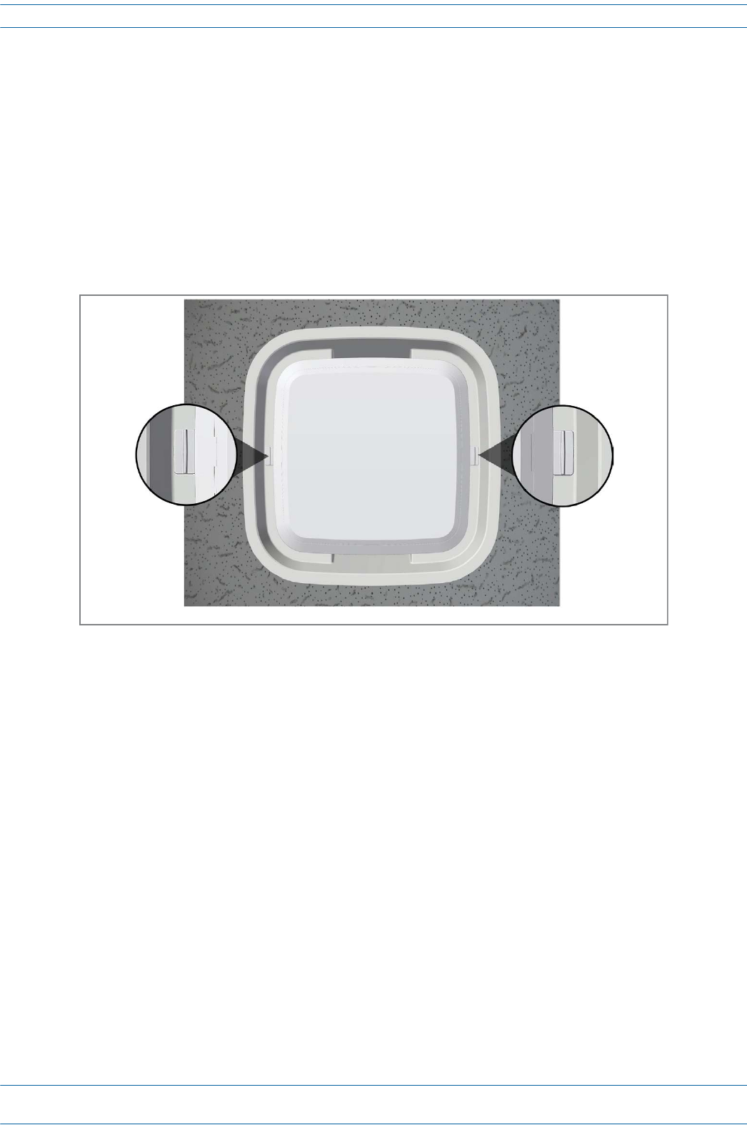
Remove a CAP L from a Ceiling Mount
ShouldyouneedtoremovetheCAPLfromtheceilingmount,dothefollowing:
1WhileholdingtheCAPLwithbothhands,pressbothreleaseslidesinwardtowardstheCAPL.
2PresstheredpowerswitchbuttonontheCAPLtoshutitdown.TheredbuttonmustbepressedBEFORE
disconnectingtheCat6Acables.TheblueLEDwillturnoffwhentheunitshutsdown.TheCAPLmayalso
beshutdownviasoftwarepriortodisconnectingthecables.
3UnplugtheCAPLcables.
4Ifagroundwireisinstalled,loosenthegroundingscrewandremovethegroundwire.
Release
slide
Release
slide
View when looking up at UAP in a ceiling mount
ION®-E Series Hardware Installation Guide M0201AA
Page 120 © June 2017 CommScope, Inc.
CAP L Maintenance
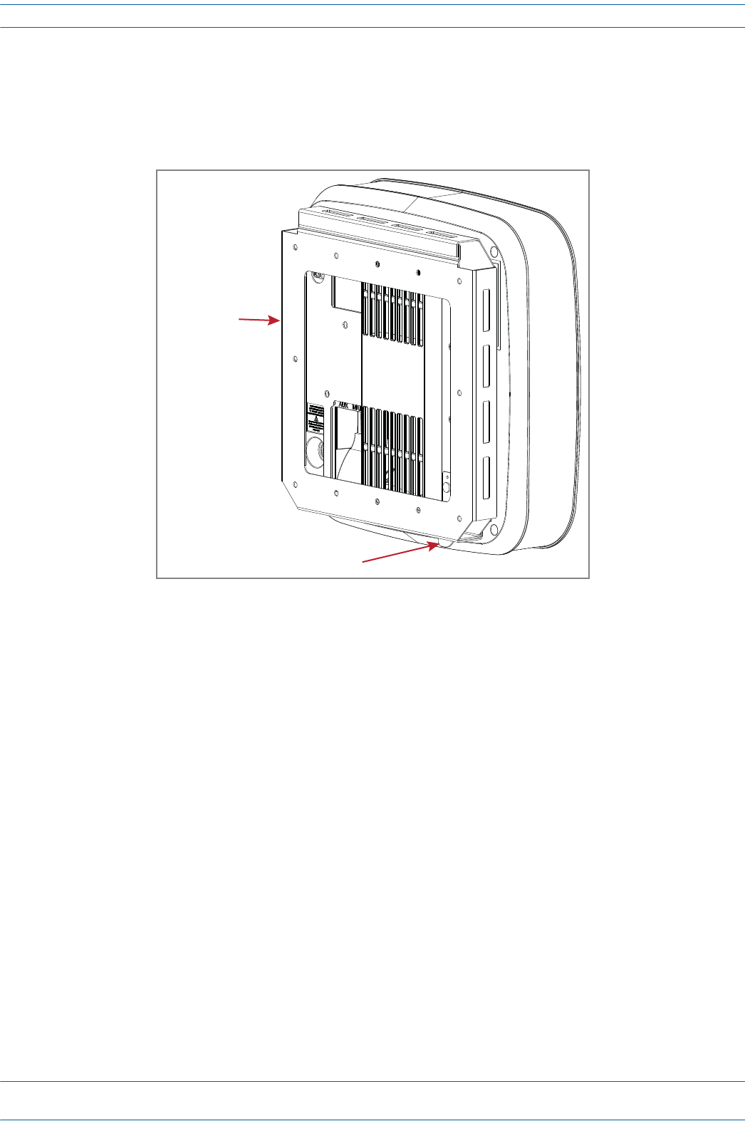
Remove a CAP L from a Wall Mount
ShouldyouneedtoremovetheCAPLfromthewallmount,dothefollowing:
1WhilesecurelysupportingtheCAPL,pressbothreleasesinwardtowardstheCAPL.
2PresstheredpowerswitchbuttonontheCAPLtoshutitdown.TheredbuttonmustbepressedBEFORE
disconnectingtheCat6Acables.TheblueLEDwillturnoffwhentheunitshutsdown.TheCAPLmayalso
beshutdownviasoftwarepriortodisconnectingthecables.
3UnplugtheCAPLcables.
4Ifagroundwireisinstalled,loosenthegroundingscrewandremovethegroundwire.
Release tab
Wall Bracket
M0201AA ION®-E Series Hardware Installation Guide
© June 2017 CommScope, Inc. Page 121
CAP L Maintenance
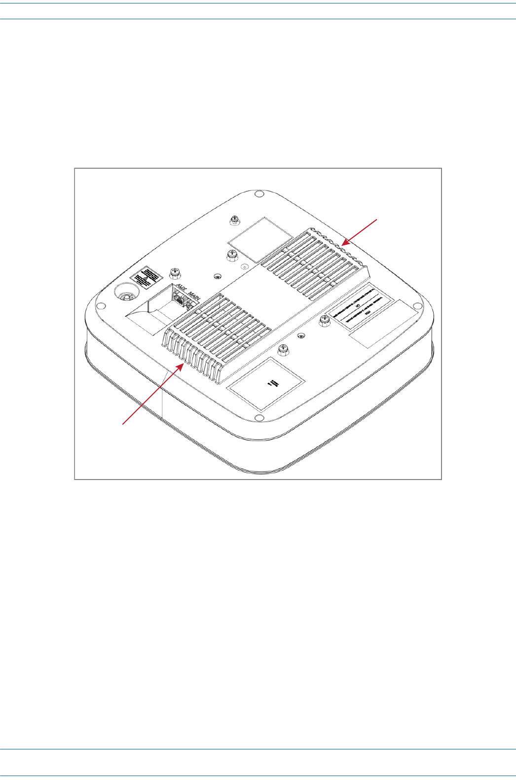
Preventative CAP L Maintenance
TheCAPLdoesnotrequirepreventativemaintenancemeasures.However,checkingthecleanlinessofthe
unitanditscomponents—particularlytheheatsink/fans—atregularly-scheduledintervalsisrecommended.
Avoidapplyingtoomuchpressurewhenusingavacuumorothermethod,asthiscandamagethefanbearings
andshortenthelifespanofthefans.
YouwillneedtoremovetheCAPLfromitsmountingtoaccessthefansitsbottom;see"RemoveaCAPLfrom
aCeilingMount”onpage119.
Fan
Fan
Boom of an Access Point Unit
(UAP is shown)
ION®-E Series Hardware Installation Guide M0201AA
Page 122 © June 2017 CommScope, Inc.
CAP L Specifications
CAP L SPECIFICATIONS
CAP L Output Specifications
UNRESOLVED: The information in this section is lifted from UAP - I do not know how much actually applies
to the CAP L
TheManufacturer'sratedoutputpowerforthisequipmentisthecompositepowerinaband.Forsituations
whenmultiplecarriersignalsarepresent,thepowerpercarrierisreduced.Forexample,twocarriersina
bandwilleachhave3dBlesspowerthanasinglecarrierinaband.Thisisimportantwheretheoutputsignal
isradiatedandcancauseinterferencetoadjacentbandusers.Thispowerreductionistobebymeansofgain
reductionandnotbyanattenuatorattheoutputofthedevice.
Lapuissancedesortienominaledufabricantpourcetéquipementestlapuissancecompositedansune
bande.Pourlessituationsoùplusieursporteusessontprésentes,lapuissanceparporteuseestréduite.Par
exemple,deuxporteusesd'unebandeaurontchacun3dBdepuissanceinférieureàcelled'uneseuleporteuse
dansunebande.Ceciestimportantlorsquelesignaldesortieestrayonnéetpeutcauserdesinterférences
auxutilisateursdebandesadjacentes.Cetteréductiondepuissancedoitêtreréaliséeparréductiondegainet
nonparunatténuateurensortiedudispositif.
Nominal passband gain per band:
Le gain nominal en bande passante
Rated mean output power per band 380 MHz - 512 MHz
La puissance moyenne de sortie par bande 380 MHz - 512 MHz
Rated mean output power per band >608 MHz
La puissance moyenne de sortie par bande >608 MHz
+18 dBm
Maximum combined mean power in mid bands 608-1000 MHz
Puissance moy-enne combinée maximale dans les bandes moyennes 608-1000 MHz
+21 dBm
Maximum combined mean power in high bands 1395-2700 MHz
Puissance moy-enne combinée maximale dans les bandes moyennes 1395-2700 MHz
+21 dBm
Input / Output Impedance
Les impédances d'entrée et de sortie, et
M0201AA ION®-E Series Hardware Installation Guide
© June 2017 CommScope, Inc. Page 123
CAP L Specifications
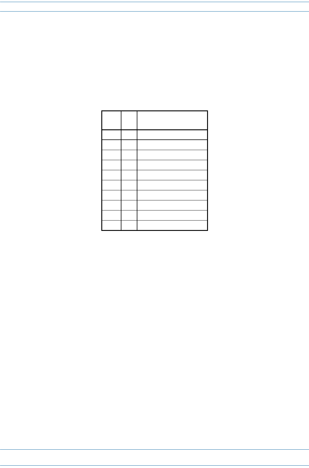
CAP L Bandwidth Specifications
UNRESOLVED: The information in this section is lifted from UAP - I do not know how much actually applies
to the CAP L
ION-Esupportsavarietyofbandsinthe380to2700MHzrange.Thefrequenciesandbandwidthslistedin
thefollowingtable,forexample,representthenominalbandwidthspecificationsforCanadaintheNorth
Americaregion.
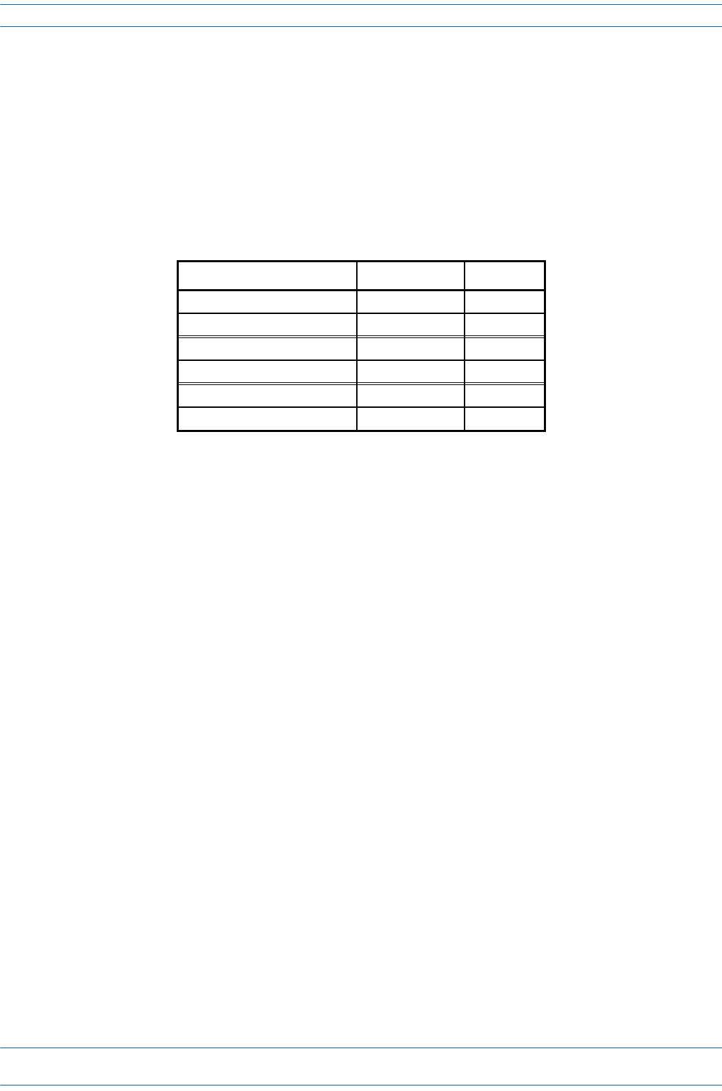
MHz MHz Nominal bandwidth (MHz)
La largeur de bande nominale
406.1 430 24
450 470 20
728 746 18
746 756 10
768 776 8
851 869 18
869 894 25
1930 1995 65
2110 2155 45
2620 2690 70

ION®-E Series Hardware Installation Guide M0201AA
Page 124 © June 2017 CommScope, Inc.
CAP L Specifications

M0201AA ION®-E Series Hardware Installation Guide
© June 2017 CommScope, Inc. Page 125
Chapter Topics Page
Contacting DCCS Global Technical Support....................................................................................................................................................... 126
Telephone Helplines..................................................................................................................................................................................... 126
Online Support..............................................................................................................................................................................................126
DCCS Technical Training .................................................................................................................................................................................... 127
Accessing ION-E Series User Documentation .................................................................................................................................................... 128
Hardware to Software Mapping Information.................................................................................................................................................... 129
ThischaptertellsyouhowtocontacttheCommScopeDistributedCoverageandCapacitySolutions(DCCS)
TechnicalSupport,findoutwhatION-Etrainingclassesareoffered,howtoaccesstheION-Euser
documentation,andhowtomapsupportedION-EsoftwarereleasestoION-Ehardware.
DCCS GLOBAL TECHNICAL SUPPORT 8

ION®-E Series Hardware Installation Guide M0201AA
Page 126 © June 2017 CommScope, Inc.
Contacting DCCS Global Technical Support
CONTACTING DCCS GLOBAL TECHNICAL SUPPORT
ThefollowingsectionstellyouhowtocontacttheCommScopeDistributedCoverageandCapacitySolutions
(DCCS)TechnicalSupportteam.Supportisavailable7daysaweek,24hoursaday.
Telephone Helplines
UsethefollowingHelplinetelephonenumberstogetlivesupport,24hoursaday:
Online Support
TogototheCommScopeDCCSSupportRequestwebsitefromwhichyoucaninitiateaTechnicalSupport
ticket,dooneofthefollowing:
•ScantheQRCodetotheright.
•IfviewingthisdocumentonlineasaPDF,clickonthefollowingURLlink:
http://www.commscope.com/wisupport
•EntertheprecedingURLintoyourwebbrowser,andthenpressENTERonyourkeyboard.
24x7 +1888-297-6433(TollfreeforU.S.andCanada)
EMEA 8:00-17:00 (UTC +1) +80073732837(TollfreeforpartsofEMEAandAustralia)
+49909969333(Tollchargeincurred)
CallstoanEMEAHelplineoutsideofthe8:00to17:00timeframewillbe
forwardedtothe24x7Helpline.

M0201AA ION®-E Series Hardware Installation Guide
© June 2017 CommScope, Inc. Page 127
DCCS Technical Training
DCCS TECHNICAL TRAINING
1ToaccesstrainingontheonlineCommScopeDASandSmallCellInstitute,dooneofthefollowing:
•ScantheQRCodetotheright.
•IfviewingthisdocumentonlineasaPDF,clickonthefollowingURLlink.
http://www.commscopetraining.com/courses/dassc/
•EntertheprecedingURLintoyourwebbrowser,andthenpressENTERonyourkeyboard.
2Reviewthecourseslistedinseparatecoursepanels;forfurtherinformationonacourse,clickitsFull
detailsbutton.Instructor-ledcoursesareconductedinNorthAmericaandEurope.Beforechoosinga
course,pleaseverifytheregion.
3Toviewthecoursescheduleandregister,clickCourse Registrationatthetopofthecoursepage;this
opensthePartner Learning Center Loginpage.
•Ifyouhaveanaccount,enteryourUsernameandPassword,andthenclickLogin.(ClickontheReset
Passwordlinkifyoudonothaveyourlogininformation.)
•Ifyoudon'thaveanaccount,clickontheCreate New User AccountlinkundertheLoginbutton,and
followtheprompts.
Onceyouhaveloggedin,youwillseealistofavailableclassdates.
4ClickthedateyoupreferandselecttheEnrollorRegisterNowbuttontoenroll.Followtheprompts
throughthepaymentprocess.
5ClickeithertheAvailable TrainingorCalendartabtoviewothertrainingcourses.
Fortrainingrelatedquestions,pleasecontacttheCommScopeDASandSmallCellInstituteatoneofthe
followingemails,asappropriateforyourlocation:
Americas: DASTrainingUS@CommScope.com
EMEA: DASTrainingEMEA@CommScope.com

ION®-E Series Hardware Installation Guide M0201AA
Page 128 © June 2017 CommScope, Inc.
Accessing ION-E Series User Documentation
ACCESSING ION-E SERIES USER DOCUMENTATION
1ScantheQRCodetotherighttogodirectlytotheCommScopeDCCSCustomer
Portal,whereyoucanaccesstheDCCSuserdocumentation.
Alternatively,youcangotothefollowingwebaddresstoaccesstheportal:
https://www.mycommscope.com
2AccesstotheCustomerPortalrequiresauseraccountandpassword.OntheSign
Inpage,dooneofthefollowing:
•Ifyouhaveanaccount,enteryourEmailaddressandPassword,andthenclickSignIn.
•Ifyoudon’thaveanaccount,clickNewuserregistration,andfollowtheprompts.
3ClickDCCStoopenthesite.
4Selectyoursite,andthenclickonaproductlinktoopentheproductpage.
5Clickonthetitleofanydocumenttoopenit.

M0201AA ION®-E Series Hardware Installation Guide
© June 2017 CommScope, Inc. Page 129
Hardware to Software Mapping Information
HARDWARE TO SOFTWARE MAPPING INFORMATION
1ScantheQRCodetotherighttoviewordownloadtheminimumsoftware
requirementsforeachoftheDCCShardwaremodules.Alternatively,youcangoto
thefollowingwebaddresstoaccesstheportal:
http://www.commscope.com/collateral/DCCS_HW_SW_Mapping/
2ClickonadocumentlinktoopenitorrightclickonthelinkandselecttheSave
targetas…optionfromthecontextualmenu.

ION®-E Series Hardware Installation Guide M0201AA
Page 130 © June 2017 CommScope, Inc.
Hardware to Software Mapping Information