Andrew Wireless System CAPL17E23 ION-E Remote Unit for cellular systems User Manual M0201AAA
Andrew Wireless System ION-E Remote Unit for cellular systems M0201AAA
Contents
- 1. users manual part 1
- 2. users manual part 2
- 3. users manual part 3
- 4. installation manual
users manual part 3
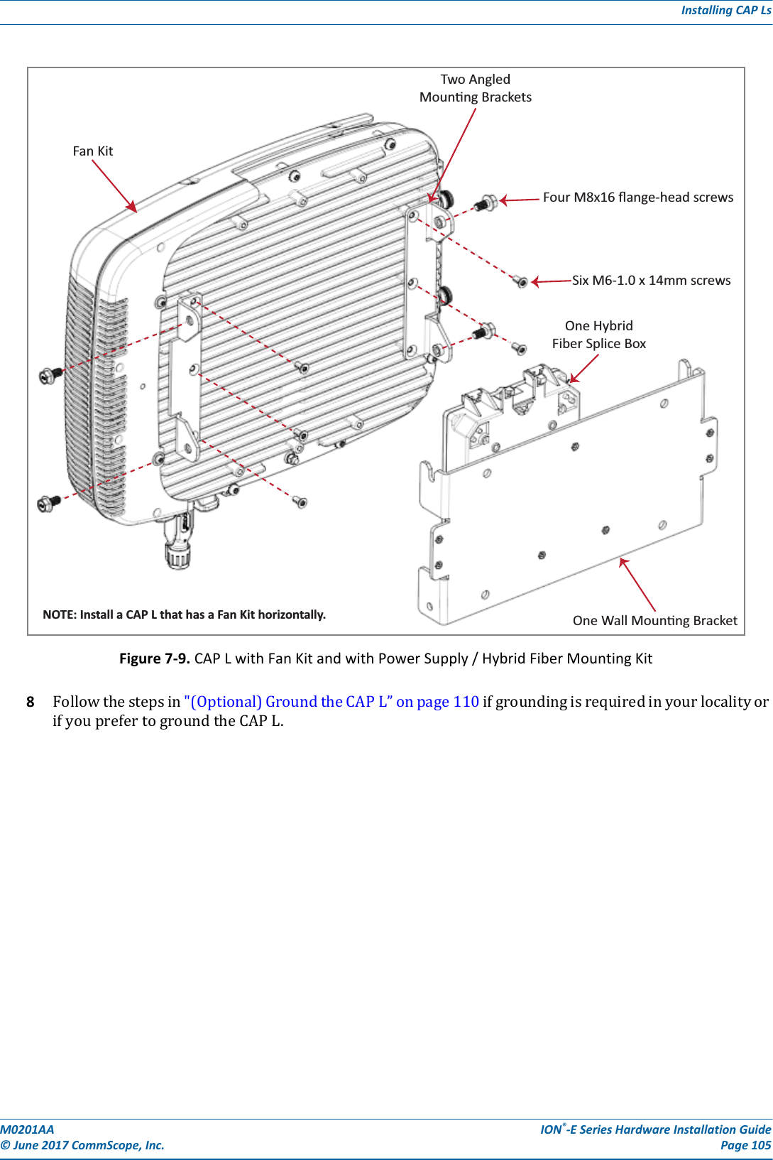
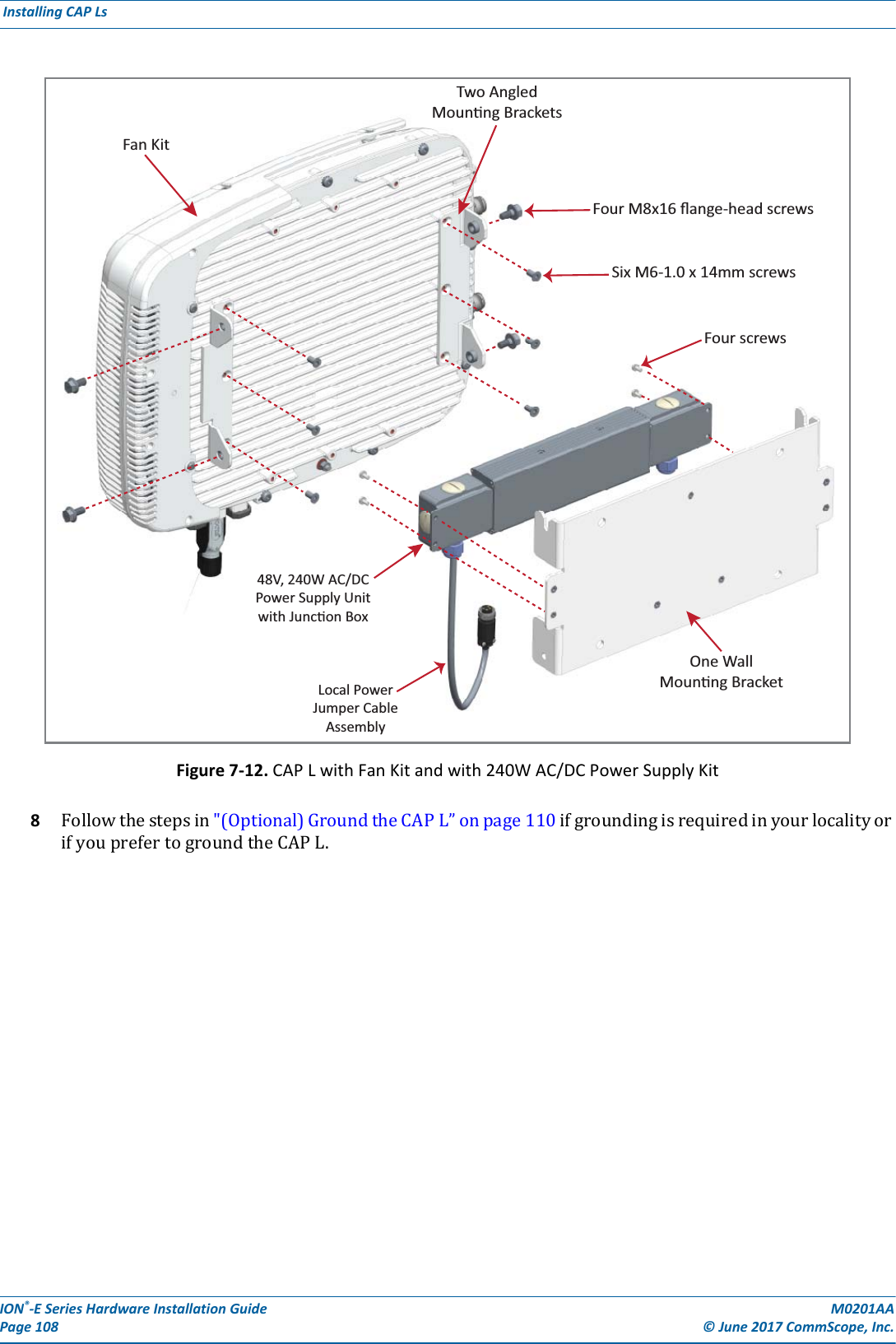
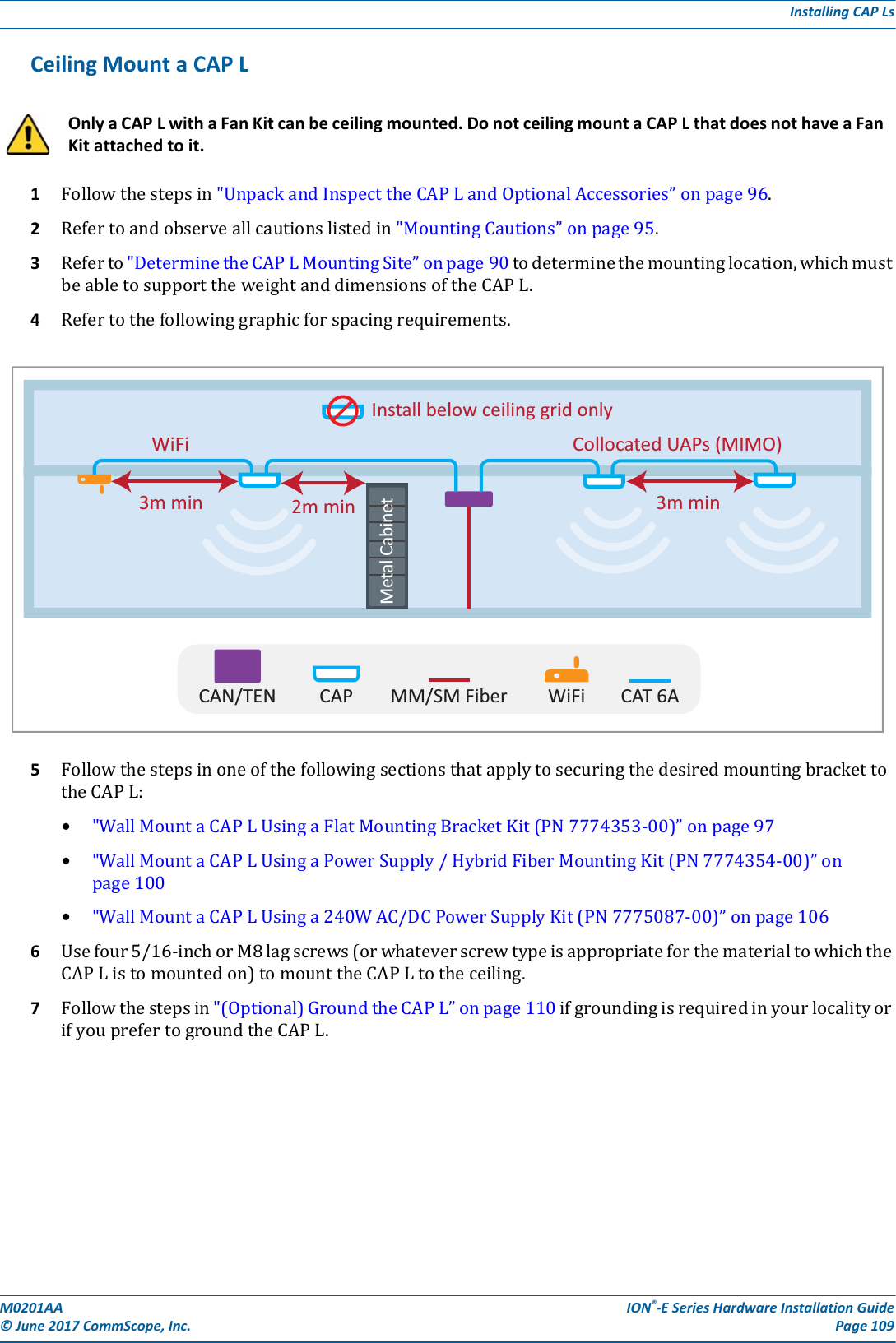
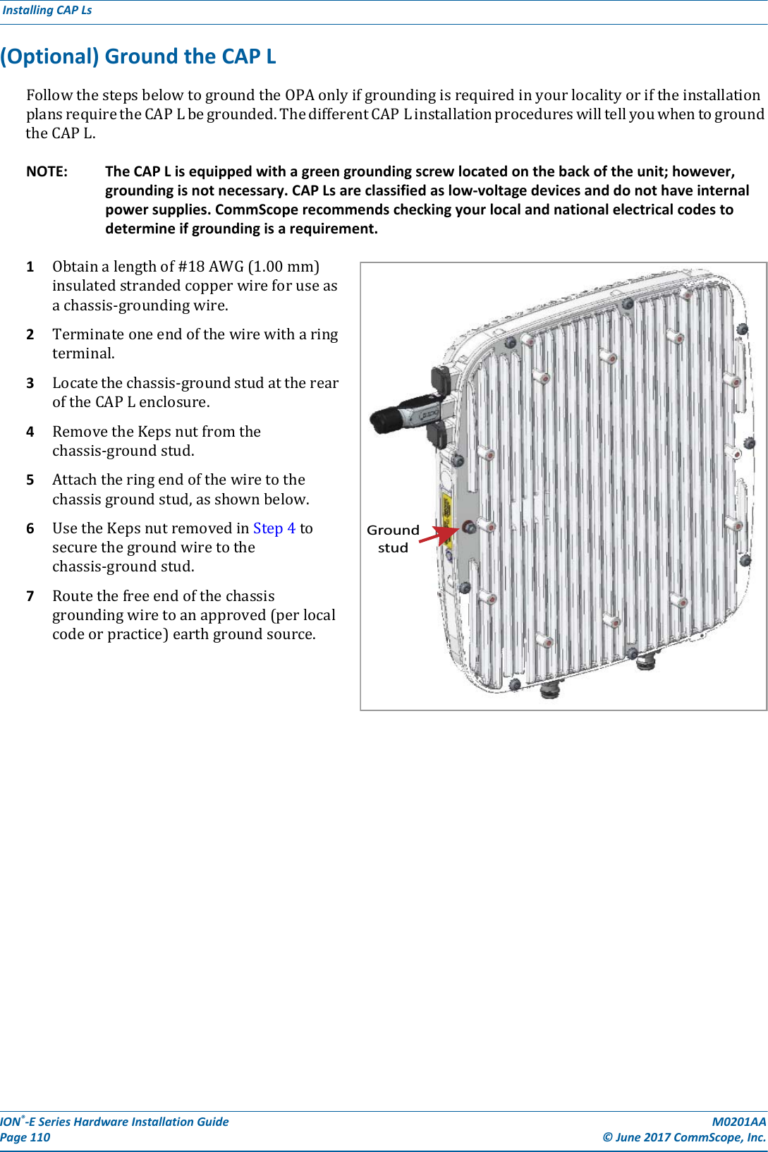
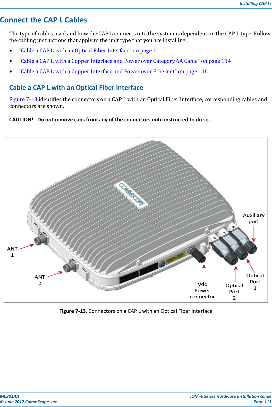
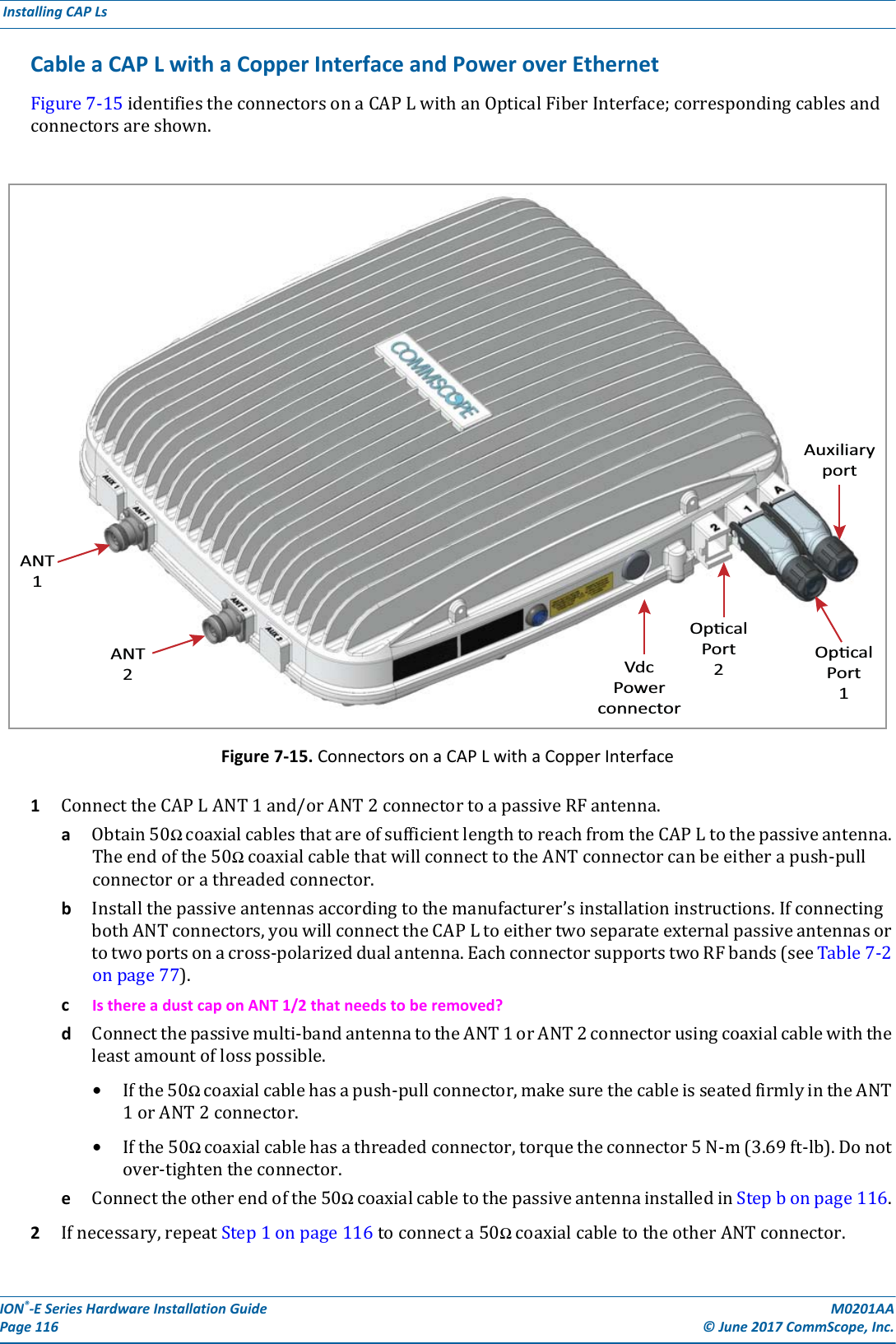
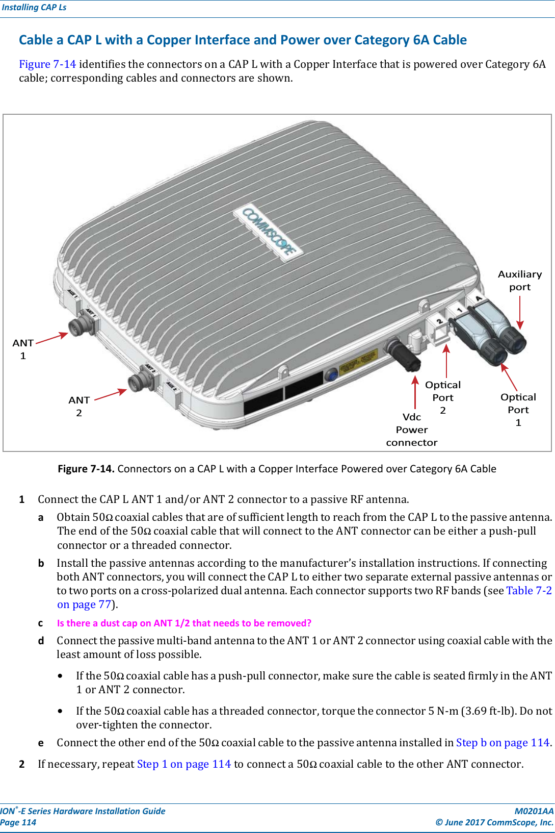
![ION®-E Series Hardware Installation Guide M0201AA Page 112 © June 2017 CommScope, Inc. Installing CAP Ls 1ConnecttheCAPLANT1and/orANT2connectortoapassiveRFantenna.aObtain50ΩcoaxialcablesthatareofsufficientlengthtoreachfromtheCAPLtothepassiveantenna.Theendofthe50ΩcoaxialcablethatwillconnecttotheANTconnectorcanbeeitherapush-pullconnectororathreadedconnector.bInstallthepassiveantennasaccordingtothemanufacturer’sinstallationinstructions.IfconnectingbothANTconnectors,youwillconnecttheCAPLtoeithertwoseparateexternalpassiveantennasortotwoportsonacross-polarizeddualantenna.EachconnectorsupportstwoRFbands(seeTable7-9).cIs there a dust cap on ANT 1/2 that needs to be removed?dConnectthepassivemulti-bandantennatotheANT1orANT2connectorusingcoaxialcablewiththeleastamountoflosspossible.•Ifthe50Ωcoaxialcablehasapush-pullconnector,makesurethecableisseatedfirmlyintheANT1orANT2connector.•Ifthe50Ωcoaxialcablehasathreadedconnector,torquetheconnector5N-m(3.69ft-lb).Donotover-tightentheconnector.eConnecttheotherendofthe50ΩcoaxialcabletothepassiveantennainstalledinStepbonpage112.2Ifnecessary,repeatStep1onpage112toconnecta50ΩcoaxialcabletotheotherANTconnector.3ConnecttheOpticalPort1connectorasappropriateforthisinstallation.aObtainSingleModeFiber(SMF)orMultiModeFiber(MMF)thatisofsufficientlengthtoreachfromtheCAPLtotheION-ECAN/TEN.[when would you use SM vs. MM?]bRemovethedustcapfromtheOpticalPort1connectorandtheconnectorsontheSMorMMfiber.cFollowthelocalcleaningtechniquetocleanOpticalPort1.dCleantheconnectorsontheSMForMMFfollowingthefibersupplier’srecommendations.eConnectoneendoftheSMForMMFtotheOpticalPort1connectorandtheotherendto[to what EXACTLY does the other end of the cable connect on the CAN/TEN or junction box?]UNRESOLVED: If Opt 1 can connect to the ION-E CAN/TEN or to a local Hybrid Fiber Junction Box to provide the main signal and power interface, when does optical transport occur over Single Mode (SM) or Multi Mode (MM) fiber? We need to identify what type of cable to use, and does the customer supply the cable or does it ship with the CAP L? Table 7-9. Mapping Frequency Bands to AntennasFrequency Band Band Combination Antenna PortAWS1700 / LTE2300 17E and 23 1AWS1700 / LTE2300 17E and 23 2GSM1800 / UMTS2100 / LTE2600 18 and 26 1GSM1800 / UMTS2100 / LTE2600 21 and 26 2AWS1700 / PCS1900 17E and 19 1AWS1700 / PCS1900 17E and 19 2](https://usermanual.wiki/Andrew-Wireless-System/CAPL17E23.users-manual-part-3/User-Guide-3453090-Page-8.png)
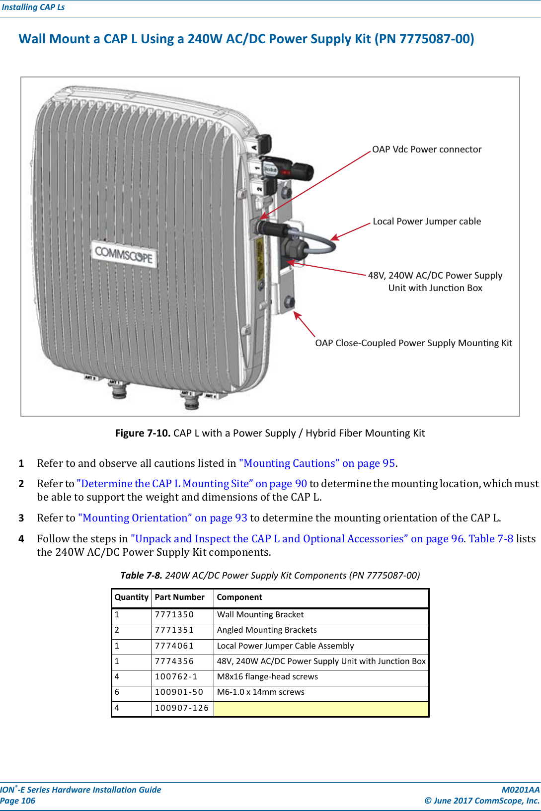
![M0201AA ION®-E Series Hardware Installation Guide© June 2017 CommScope, Inc. Page 113Installing CAP Ls4Ifappropriateforthisinstallation,connecttheOpticalPort2connector.aRaisetheleverontheEMI/IP67caponOpticalPort2connectorandremovethecap.bRemovethecapsfromtheconnectorsontheSMorMMfiber.cFollowthelocalcleaningtechniquetocleanOpticalPort2.dCleantheconnectorsontheSMForMMFfollowingthefibersupplier’srecommendations.eConnectoneendoftheSMForMMFtotheOpticalPort2connectorandtheotherendto[to what EXACTLY does the other end of the cable connect on the CAN/TEN or junction box?]UNRESOLVED: If Opt 2 can connect to a local Hybrid Fiber Junction Box or a cascaded CAP L to provide the main signal and power interface, when does optical transport occur over Single Mode (SM) or Multi Mode (MM) fiber? We need to identify what type of cable to use, and does the customer supply the cable or does it ship with the CAP L?5ConnecttheAuxiliaryconnectorasappropriateforthisinstallation.aRaisetheleverontheEMI/IP67capontheAuxiliaryconnectorandremovethecap.UNRESOLVED: AUX port can connect to external Ethernet devices such as WiFi and IP cameras. What type of cable do you use for each? Cabling is via the appropriate CAT cable for the protocol; this model supports an 1000 BASE-T and 802.3at Class 3 PoE (minimum) Ethernet connection. We need to identify what type of cable to use, and does the customer supply the cable or does it ship with the CAP L? UNRESOLVED: Verify that maximum attached cable length is 3 meters (9.8 feet).UNRESOLVED: To what does the other end of the cable connect to on external Ethernet devices such as WiFi and IP cameras?6ConnecttheVdcPowerconnectorasappropriateforthisinstallation.aFindtheLocalPowerJumperCableAssemblythatwasshippedwiththemountingkit.bConnectthefour-pinconnectortotheVdcPowerconnectorontheCAPL.UNRESOLVED: Spec stated that this model can connect to a local or external power supply, or to a Hybrid Fiber Junction Box, is the power cable the same for all three options? For each option, to what does the power cable connect? TheCAPLispoweredonassoonasyouconnecttheLocalPowerJumperCableAssemblytoapowersource;see"PoweringaCAPL”onpage82.](https://usermanual.wiki/Andrew-Wireless-System/CAPL17E23.users-manual-part-3/User-Guide-3453090-Page-9.png)
![M0201AA ION®-E Series Hardware Installation Guide© June 2017 CommScope, Inc. Page 115Installing CAP Ls3ConnecttheOpticalPort1connectorasappropriateforthisinstallation.aObtainSingleModeFiber(SMF)orMultiModeFiber(MMF)thatisofsufficientlengthtoreachfromtheCAPLtotheION-ECAN/TEN.[when would you use SM vs. MM?]bRemovethedustcapfromtheOpticalPort1connectorandtheconnectorsontheSMorMMfiber.cFollowthelocalcleaningtechniquetocleanOpticalPort1.dCleantheconnectorsontheSMForMMFfollowingthefibersupplier’srecommendations.eConnectoneendoftheSMForMMFtotheOpticalPort1connectorandtheotherendto[to what EXACTLY does the other end of the cable connect on the CAN/TEN or junction box?]UNRESOLVED: Opt 1 connects to the ION-E CAN/TEN to provide the main signal and power interface. We need to identify what type of cable to use, and does the customer supply the cable or does it ship with the CAP L? NOTE: The Optical Port 2 connector is plugged as it is not used in this configuration.4ConnecttheAuxiliaryconnectorasappropriateforthisinstallation.aRaisetheleverontheEMI/IP67capontheAuxiliaryconnectorandremovethecap.UNRESOLVED: The AUX port provides a cascade connection to additional local power or CAP L, or provides a connection to external Ethernet devices such as WiFi and IP cameras. Spec stated that cabling is via the appropriate CAT cable for installed unit protocol—what cable type(s) are supported for each unit type to which it can connect? UNRESOLVED: Verify that maximum attached cable length is 3 meters (9.8 feet).UNRESOLVED: To what does the other end of the cable connect to on external Ethernet devices such as WiFi and IP cameras?5ConnecttheVdcPowerconnectorasappropriateforthisinstallation.aFindtheLocalPowerJumperCableAssemblythatwasshippedwiththemountingkit.bConnectthefour-pinconnectortotheVdcPowerconnectorontheCAPL.TheCAPLispoweredonassoonasyouconnecttheLocalPowerJumperCableAssemblytoapowersource;see"PoweringaCAPL”onpage82.UNRESOLVED: Spec stated that this model can connect to a local or external power supply, for each option, to what does the power cable connect?](https://usermanual.wiki/Andrew-Wireless-System/CAPL17E23.users-manual-part-3/User-Guide-3453090-Page-11.png)