Andrew Wireless System CAPL17E23 ION-E Remote Unit for cellular systems User Manual M0201AAA
Andrew Wireless System ION-E Remote Unit for cellular systems M0201AAA
Contents
- 1. users manual part 1
- 2. users manual part 2
- 3. users manual part 3
- 4. installation manual
users manual part 1
ION®-E Series Hardware
Installation Guide • M0201AAA • June 2017

DISCLAIMER
ThisdocumenthasbeendevelopedbyCommScope,andisintendedfortheuseofitscustomersandcustomersupport
personnel.Theinformationinthisdocumentissubjecttochangewithoutnotice.Whileeveryefforthasbeenmadeto
eliminateerrors,CommScopedisclaimsliabilityforanydifficultiesarisingfromtheinterpretationoftheinformation
containedherein.Theinformationcontainedhereindoesnotclaimtocoveralldetailsorvariationsinequipment,norto
provideforeverypossibleincidenttobemetinconnectionwithinstallation,operation,ormaintenance.Thisdocument
describestheperformanceoftheproductunderthedefinedoperationalconditionsanddoesnotcovertheperformance
underadverseordisturbedconditions.Shouldfurtherinformationbedesired,orshouldparticularproblemsarisewhichare
notcoveredsufficientlyforthepurchaser'spurposes,contactCommScope.
CommScopereservestherighttochangeallhardwareandsoftwarecharacteristicswithoutnotice.
COPYRIGHT
©2017CommScope,Inc.AllRightsReserved.
Thisdocumentisprotectedbycopyright.Nopartofthisdocumentmaybereproduced,storedinaretrievalsystem,or
transmitted,inanyformorbyanymeans,electronic,mechanicalphotocopying,recording,orotherwisewithouttheprior
writtenpermissionofCommScope.
Forpatentsseewww.cs-pat.com.
TRADEMARKS
Alltrademarksidentifiedby®or™areregisteredtrademarksortrademarks,respectively,ofCommScope,Inc.Namesof
otherproductsmentionedhereinareusedforidentificationpurposesonlyandmaybetrademarksand/orregistered
trademarksoftheirrespectivecompanies.
AndrewWirelessSystemsGmbH,30-June-2017
This is NOT a CONSUMER device. It is designed for installation by FCC LICENSEES and QUALIFIED
INSTALLERS. You MUST have an FCC LICENSE or express consent of an FCC Licensee to operate this device.
Unauthorized use may result in significant forfeiture penalties, including penalties in excess of $100,000
for each continuing violation.
This is NOT a CONSUMER device. It is designed for installation by FCC LICENSEES and QUALIFIED
INSTALLERS. You MUST have an FCC LICENSE or express consent of an FCC Licensee to operate this device.
You MUST register Class B signal boosters (as defined in 47 CFR 90.219) online at
www.fcc.gov/signal-boosters/registration. Unauthorized use may result in significant forfeiture penalties,
including penalties in excess of $100,000 for each continuing violation.

M0201AAA CPRI Digital Interface Unit Installation and Provisioning Guide
© June 2017 CommScope, Inc. Page iii
1 Using this Document ____________________________________________________________________________________1
Document Revision History ................................................................................................................................................................................... 2
Document Cautions and Notes.............................................................................................................................................................................. 3
Abbreviations Used in this Guide .......................................................................................................................................................................... 4
2 ION-E Series Hardware Overview __________________________________________________________________________5
ION-E Series System Overview .............................................................................................................................................................................. 6
Safely Working with ION-E Hardware ................................................................................................................................................................... 9
Equipment Symbols with CE Compliance ......................................................................................................................................................... 9
Health and Safety Precautions .........................................................................................................................................................................9
Property Damage Warnings ........................................................................................................................................................................... 10
Compliance and Standards Certification ............................................................................................................................................................. 11
FCC RF Exposure Requirements...................................................................................................................................................................... 11
EMC Standards ............................................................................................................................................................................................... 11
FCC and IC Standards...................................................................................................................................................................................... 12
3 WCS-2 and WCS-4 Subracks and Modules __________________________________________________________________13
WCS-2 and WCS-4 Subracks and Modules ..........................................................................................................................................................14
WCS Subrack Front Panel Card Slots and GUI Identification .......................................................................................................................... 15
WCS Subrack Back Panel Connectors .............................................................................................................................................................16
WCS Subrack Alarm Connector....................................................................................................................................................................... 17
WCS Fan Modules and Filters ......................................................................................................................................................................... 18
System User Interface Card (SUI) ................................................................................................................................................................... 19
RF Donor Card (RFD)....................................................................................................................................................................................... 20
Optical Transport Card (OPT).......................................................................................................................................................................... 21
Copper Transport Card (CAT).......................................................................................................................................................................... 22
Auxiliary Unit Transport Card (AUT) ............................................................................................................................................................... 23
Installing Subracks and PSUs in an Equipment Rack ........................................................................................................................................... 24
Rack-Mounting the Subracks and PSU............................................................................................................................................................24
Connect the Subrack and PSU Power and Communication Cables ................................................................................................................ 25
Install the CAN and TEN Cards........................................................................................................................................................................ 27
Install SFP+ Transceivers in the OPT Cards..................................................................................................................................................... 28
Connect the RFD Cards ................................................................................................................................................................................... 29
Connect the CAT Cards ................................................................................................................................................................................... 30
Connect the AUT Cards................................................................................................................................................................................... 32
4 Point of Interface (e-POI) Subracks _______________________________________________________________________35
Point Of Interface (e-POI) Subrack ...................................................................................................................................................................... 36
e-POI Subrack Back Panel Connectors............................................................................................................................................................ 36
Interface Card (IFC)......................................................................................................................................................................................... 37
e-POI Module.................................................................................................................................................................................................. 38
Installing an e-POI Subracks and Modules .......................................................................................................................................................... 39
Removing an e-POI Module from an e-POI Subrack............................................................................................................................................ 40
e-POI Subrack and Component Specifications ....................................................................................................................................................41
5 Power Supply Unit (PSU)________________________________________________________________________________43
Power Supply Unit (PSU) ..................................................................................................................................................................................... 44
PSU Modules and Connectors ........................................................................................................................................................................ 44
12 Vdc Power Module LEDs............................................................................................................................................................................ 45
57 Vdc Power Module LEDs............................................................................................................................................................................ 46
Installing PSUs ..................................................................................................................................................................................................... 47
TABLE OF CONTENTS

CPRI Digital Interface Unit Installation and Provisioning Guide M0201AAA Issue 1
Page iv © June 2017 CommScope, Inc.
Table of Contents
6 Universal Access Points_________________________________________________________________________________49
Identifying UAPs in the ION-E Software ......................................................................................................................................................... 50
UAPs and UAP-N25s ....................................................................................................................................................................................... 51
UAP-X.............................................................................................................................................................................................................. 52
Installing UAPs..................................................................................................................................................................................................... 53
Using the UAP Ceiling Mount Assembly (PN 7683182-00) ............................................................................................................................. 53
Required Tools for a Standard UAP Ceiling Mount .................................................................................................................................. 53
Unpack and Inspect the Ceiling Mount Assembly.................................................................................................................................... 53
Standard Ceiling Mount Overview ........................................................................................................................................................... 54
Standard Ceiling Mount Installation Steps............................................................................................................................................... 55
Mounting a UAP Using a UAP Quick Release Ceiling Mount Kit..................................................................................................................... 57
Required Tools for a Quick Release Ceiling Mount Kit............................................................................................................................. 57
Unpack and Inspect the Quick Release Ceiling Mount Kit ....................................................................................................................... 58
Overview of Using a Quick Release Ceiling Mount Kit ............................................................................................................................. 58
Mount the UAP to the Ceiling ..................................................................................................................................................................59
Connect the UAP Cables........................................................................................................................................................................... 61
Install the UAP.......................................................................................................................................................................................... 62
Mounting a UAP to a Wall Using the UAP Wall Mounting Kit (PN 7683181-00) ............................................................................................ 63
Required Tools for a Wall Mount............................................................................................................................................................. 63
Unpack and Inspect the Wall Mounting Kit.............................................................................................................................................. 64
Mount the UAP to a Wall ......................................................................................................................................................................... 64
UAP, UAP-N25, and UAP-X Cable Requirements............................................................................................................................................ 67
Cascading a UAP, UAP-X, or UAP-N25 ............................................................................................................................................................68
UAP Maintenance................................................................................................................................................................................................ 69
Remove a UAP from a Ceiling Mount .............................................................................................................................................................69
Remove a UAP from a Wall Mount................................................................................................................................................................. 70
Preventative UAP Maintenance ..................................................................................................................................................................... 71
UAP Specifications............................................................................................................................................................................................... 72
UAP Output Specifications.............................................................................................................................................................................. 72
UAP Bandwidth Specifications........................................................................................................................................................................ 73
7 Carrier Access Point, Low Power (CAP L) ___________________________________________________________________75
Identifying CAP Ls in the ION-E Software ............................................................................................................................................................ 76
CAP L Overview............................................................................................................................................................................................... 77
CAP L Connectors, Ports, and LEDs........................................................................................................................................................... 78
CAP L with an Optical Fiber Interface....................................................................................................................................................... 79
CAP L with a Copper Interface and External DC Power............................................................................................................................ 80
CAP L with a Copper Interface and Power Cat 6A Cable .......................................................................................................................... 81
Fan Interface Port..................................................................................................................................................................................... 82
Powering a CAP L...................................................................................................................................................................................... 82
CAP L Accessory Options .......................................................................................................................................................................... 83
Fan Kit (PN 7724090-00) .................................................................................................................................................................... 84
CAP L Flat Mounting Bracket Kit (PN 7774353-00) ............................................................................................................................ 85
CAP L Power Supply / Hybrid Fiber Mounting Kit (PN 7774354-00) .................................................................................................. 86
CAP L 240W AC/DC Power Supply Kit (PN 7775087-00) .................................................................................................................... 87
CAP OCTIS Kits (PNs 7773582-00 and 7760652-00)........................................................................................................................... 88
Installing CAP Ls................................................................................................................................................................................................... 89
Prepare for Installation................................................................................................................................................................................... 89
Recommended Tools................................................................................................................................................................................ 89
Recommended Materials.........................................................................................................................................................................89
Determine the Power Consumption of the CAP L .................................................................................................................................... 90
Determine the CAP L Mounting Site ........................................................................................................................................................ 90
Mounting Orientation .............................................................................................................................................................................. 93
Mounting Cautions................................................................................................................................................................................... 95
General Installation Safety Requirements ............................................................................................................................................... 95
Guard Against Damage from Electro-Static Discharge............................................................................................................................. 95
Unpack and Inspect the CAP L and Optional Accessories ........................................................................................................................ 96

M0201AAA CPRI Digital Interface Unit Installation and Provisioning Guide
© June 2017 CommScope, Inc. Page v
Table of Contents
Installing a CAP L.............................................................................................................................................................................................96
Mount the CAP L ...................................................................................................................................................................................... 96
Flat-Surface Mount a CAP L ............................................................................................................................................................... 97
Wall Mount a CAP L Using a Flat Mounting Bracket Kit (PN 7774353-00)......................................................................................... 97
Wall Mount a CAP L Using a Power Supply / Hybrid Fiber Mounting Kit (PN 7774354-00)............................................................. 100
Wall Mount a CAP L Using a 240W AC/DC Power Supply Kit (PN 7775087-00)...............................................................................106
Ceiling Mount a CAP L......................................................................................................................................................................109
(Optional) Ground the CAP L..................................................................................................................................................................110
Connect the CAP L Cables.......................................................................................................................................................................111
Cable a CAP L with an Optical Fiber Interface..................................................................................................................................111
Cable a CAP L with a Copper Interface and Power over Category 6A Cable.................................................................................... 114
Cable a CAP L with a Copper Interface and Power over Ethernet ...................................................................................................116
Cascading CAP Ls ............................................................................................................................................................................................... 118
CAP L Maintenance ........................................................................................................................................................................................... 119
Remove a CAP L from a Ceiling Mount......................................................................................................................................................... 119
Remove a CAP L from a Wall Mount ............................................................................................................................................................ 120
Preventative CAP L Maintenance ................................................................................................................................................................. 121
CAP L Specifications...........................................................................................................................................................................................122
CAP L Output Specifications ......................................................................................................................................................................... 122
CAP L Bandwidth Specifications.................................................................................................................................................................... 123
8 DCCS Global Technical Support__________________________________________________________________________125
Contacting DCCS Global Technical Support....................................................................................................................................................... 126
Telephone Helplines..................................................................................................................................................................................... 126
Online Support..............................................................................................................................................................................................126
DCCS Technical Training .................................................................................................................................................................................... 127
Accessing ION-E Series User Documentation.................................................................................................................................................... 128
Hardware to Software Mapping Information.................................................................................................................................................... 129

CPRI Digital Interface Unit Installation and Provisioning Guide M0201AAA Issue 1
Page vi © June 2017 CommScope, Inc.
Table of Contents

M0201AA ION®-E Series Hardware Installation Guide
© June 2017 CommScope, Inc. Page 1
Chapter Topics Page
Document Revision History ................................................................................................................................................................................... 2
Document Cautions and Notes.............................................................................................................................................................................. 3
Abbreviations Used in this Guide .......................................................................................................................................................................... 4
Thischapterprovidesinformationonhowtousethishardwareinstallationguide.
USING THIS DOCUMENT 1

ION®-E Series Hardware Installation Guide M0201AA
Page 2 © June 2017 CommScope, Inc.
Document Revision History
DOCUMENT REVISION HISTORY
Document # Document Date Technical Updates
M0201AAA June 2017 Initial release. Introduces the new Carrier Access Point, Low Power (CAPL), and replaces the
following ION-E Series user documentation:
• hardware section of the ION-E Series Software Version 2.0.0 User’s Manual (PN M0201A0D)
•ION-E Series Instructions for WCS Subracks (PN M0201A1C)
•ION-E Series Instructions for Ceiling Mount UAP (PN M0201A2A)
•ION-E Series Instructions for UAP Wall Mount (PN M0201A3B)
•ION-E Series Instructions for UAP (PN M0201A4A)
•ION-E Series Instructions for SUI, RFD, CAT, OPT, and AUT Cards (PN M0201A5B)
•ION-E Series Instructions for e-POI (PN M0201A7B)
•ION-E Series Instructions for UAP Quick Release Ceiling Mount (PN M0201A8A).

M0201AA ION®-E Series Hardware Installation Guide
© June 2017 CommScope, Inc. Page 3
Document Cautions and Notes
DOCUMENT CAUTIONS AND NOTES
Thisdocumentcontainsnotes,cautions,andwarnings.Ingeneral,cautions,warnings,andnotesindicatethe
following:
The icon to the left is used to indicate a caution or warning. Cautions and warnings indicate operations or
steps that could cause personal injury, induce a safety problem in a managed device, destroy or corrupt
information, or interrupt or stop services.
The icon to the left indicates a caution or warning that pertains to laser equipment.
The icon to the left is indicates a caution or warning that pertains to Radio Frequency (RF).
The icon to the left is indicates a Note. Notes provide information about special circumstances.

ION®-E Series Hardware Installation Guide M0201AA
Page 4 © June 2017 CommScope, Inc.
Abbreviations Used in this Guide
ABBREVIATIONS USED IN THIS GUIDE
AUT Auxiliary Transport LED Light Emitting Diode
AUX Auxiliary MHz Megahertz
CCelsius Mm Millimeter
CAN Central Area Node MMF Multi-Mode Fiber
CAP L Carrier Access Point, Low Power NC Normally Closed
Cat Category NO Normally Open
CAT Copper Transport OAP Optimized Access Point
COM Communication or Common OPT Optical Transport
dB Decibel PN Part Number
dBc Decibels (referenced to the carrier) PoCAT Power over Cate-gory 6A cable
dBm Decibel-milliwatts PoE Power over Ethernet
DC Direct Current POI Point of Interface
EFTA European Free Trade Association RAN Regional-Area Network
EMC Electromagnetic Compatibility RF Radio Frequency
EU European Union RFD RF Donor
FFahrenheit RTN Return
FCC Federal Communications Commission RU Rack Unit
Gb Gigabyte SFP Small Form-Factor Pluggable
Gbps Gigabits per second SMF Single-Mode Fiber
GHz Gigahertz SUI System User Inter-face
IC Industry Canada TEN Transport Expan-sion Node
IFC Interface Card UAP Universal Access Point
kg Kilogram Vdc Volts, direct cur-rent
LCD Liquid-Crystal Display WWatts

M0201AA ION®-E Series Hardware Installation Guide
© June 2017 CommScope, Inc. Page 5
Chapter Topics Page
ION-E Series System Overview .............................................................................................................................................................................. 6
Safely Working with ION-E Hardware ................................................................................................................................................................... 9
Equipment Symbols with CE Compliance ......................................................................................................................................................... 9
Health and Safety Precautions .........................................................................................................................................................................9
Property Damage Warnings ........................................................................................................................................................................... 10
Compliance and Standards Certification ............................................................................................................................................................. 11
FCC RF Exposure Requirements...................................................................................................................................................................... 11
EMC Standards ............................................................................................................................................................................................... 11
FCC and IC Standards...................................................................................................................................................................................... 12
ThischapterprovidesinformationontheseparatehardwarecomponentsthatanION-ESeriessystemcan
comprise.
ION-E SERIES HARDWARE OVERVIEW 2
ION®-E Series Hardware Installation Guide M0201AA
Page 6 © June 2017 CommScope, Inc.
ION-E Series System Overview
ION-E SERIES SYSTEM OVERVIEW
TheION-EisaunifiedwirelessinfrastructureplatformdefinedaroundITbasedarchitecture.Itbrings
togetherlicensedwirelessandpower,plusGigabitEthernetforWiFiintoonewirelesssystemthatcanscale
tobuildingsizeandistechnologyandspectrumagnosticandadaptive.
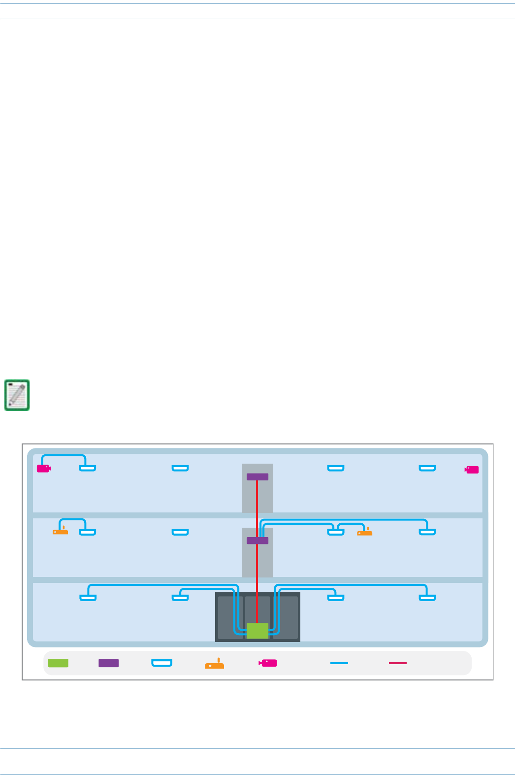
AbasicION-Esystemcomprisesthefollowingmaincomponents,asshowninFigure2-1.
•CentralAreaNode(CAN)—providesserver-levelcontrolandprimarysignaldistribution.2Uand4U
subrackoptionsareavailable.
•TransportExpansionNode(TEN)—connectstoaCANusingMulti-ModeorSingle-Modefiberasa
secondarydistributionpoint.2Uand4Usubrackoptionsareavailable.
•AccessPoint—connectsCAN/TENtoantennasorotherwirelessdevices,andcanbeanyofthefollowing.
–UniversalAccessPoint(UAP)—connectstheCAN/TENtoaninternalantenna;receivesdataand
powerthroughCategory6Atwistedpaircabling.SupportsGigabitEthernetforWiFi,IPcameras,or
otherdevicesinadditiontowirelessoveracommoncable.
–UAP-X—connectstheCAN/TENtoanexternalantenna;otherwisefunctionsthesameasthe
standardUAP.
–CarrierAccessPoint,LowPower(CAPL)—interfaceswiththeCAN/TENviaaCAT6Acable,orvia
anopticallink.Onthedownlink,theCAPLconvertssomeorallofthedataarrivingattheCAPLto
analogsignalsandsendsthemtotheanantenna.Ontheuplink,receivedsignalsaredigitizedand
serializedintodatastreamswhicharesentbacktotheCAN/TEN.EachCAPLcontainsuptofour
transceiverpathsforRFcoverage.
Figure 2-1. Basic ION-E System
A WCS-2 and a WCS-4 can be configured for use as a CAN or a TEN. When the information in this guide
applies to both configurations, the term “CAN/TEN” is used. When the information pertains to only one
of the configurations, that configuration will be identified singularly as “CAN” or “TEN.”
CAN TEN WiFi IP CameraUAP MM/SM Fiber
Cat6A

M0201AA ION®-E Series Hardware Installation Guide
© June 2017 CommScope, Inc. Page 7
ION-E Series System Overview
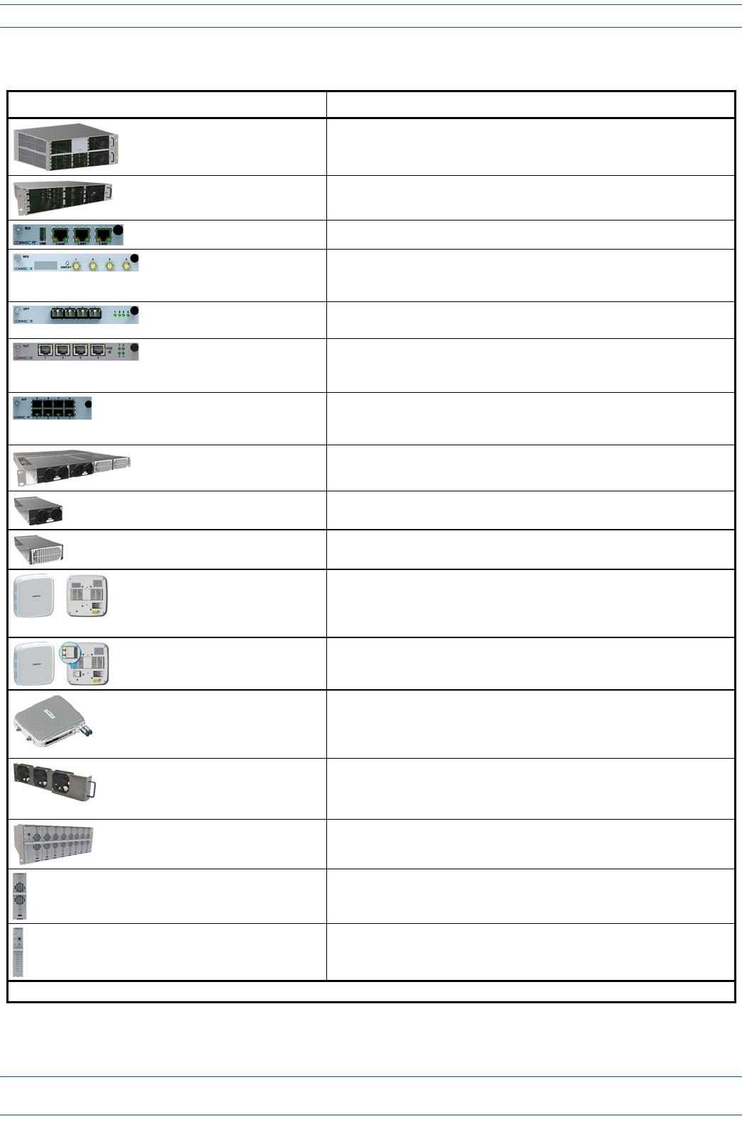
TheinformationinthisdocumentguidesyouthroughtheinstallationofaCommScopeION®-Esystem,which
supportstheION-EsystemcomponentsidentifiedinTable2-1onpage8(componentgraphicsarenotscaled
tosize).
ForinformationonhowtofindtheminimumsoftwarerequirementsforION-Ehardware,referto"Hardware
toSoftwareMappingInformation”onpage129.
ION®-E Series Hardware Installation Guide M0201AA
Page 8 © June 2017 CommScope, Inc.
ION-E Series System Overview
Table 2-1. ION-E Series Hardware System Components Supported in this Manual
Component Description
WCS-4 Subrack—CAN or TEN The WCS-4 Subrack is typically used as a CAN but can also serve as a TEN.
WCS-2 Subrack—TEN or CAN The WCS-2 Subrack is typically used as a TEN, but can also serve as a CAN.
System User Interface Card (SUI) The SUI provides local and LAN Ethernet connections and a USB port.
RF Donor Card (RFD) The RFD is the interface for RF signals between the CAN and the BTS or
eNode-B. Its four QMA female ports simultaneously transmits and receives
signals.
Optical Transport Card (OPT) The OPT provides a 10 Gb fiber connection between a CAN/TEN. Each OPT
Card supports up to four SFP+ transceivers.
Copper Transport Card (CAT) The CAT Card provides 10 Gb Cat6A connections between the CAN/TEN and
the UAP.1 CAT Cards also supply the remote power over Cat6A to the UAPs.
Each CAT Card supports a maximum of six UAPs.
Auxiliary Unit Transport Card
(AUT)
The AUT Card provides a 1 Gb pass-through connection between the
CAN/TEN and the UAP for WiFi, IP cameras, or other 1 Gb Ethernet devices
(and 100Mb devices in a future release).
Power Supply Unit (PSU) The PSU houses two 12 Vdc Power Modules and two 57 Vdc Power Modules,
which supply power to the WCS subracks, UAPs, and connected devices.
12 Vdc Power Module A 12 Vdc Module plugs into the Power Supply Subrack to provide 12 Vdc
power to the WCS and e-POI subracks.
57 Vdc Power Module A 57 Vdc Module plugs into the Power Supply Subrack to provide remote
power over Cat6A for the UAP and devices connected to the UAP.
UAP, UAP-N25 The Universal Access Point (UAP), which is connected to the ION-E system via
Cat6A cabling, uses its internal antennas to transmit and receive over-the-air
signals. It also supports Ethernet backhaul or an additional UAP through a
second RJ45 jack.
UAP-X The UAP-X is functionally identical to the UAP, but is designed to work with
external antennas. A UAP-X has two QMA Female antenna ports that connect
to external antennas, one each for Transmit (TX) and Receive (RX).
CAP L Carrier Access Point, Low Power (CAP L) provides data and power through
Copper, Single-Mode Fiber (SMF), or Multi-Mode Fiber (MMF), and supports
Gigabit Ethernet for WiFi, IP cameras, or other devices in addition to wireless
over a common cable.
Fan Module The Fan Tray and Filter Modules cool the WCS and all of its Cards.
• An AWCS-2 requires one Fan Tray.
• A WCS-4 requires two Fan Trays.
e-POI Subrack The e-POI Subrack supports up to eight e-POI RFMs and one IFC Module.
Point of Interface Card
(e-POI RFM)
The e-POI-RFM Card is a low PIM attenuator that reduces high power RF
signals from their source by 30 dB to interface with the RFD Cards.
Interface Card (IFC) The IFC is used to set the subrack number of the e-POI subrack. It also
provides a Status LED for each of the e-POI Modules in the subrack.
1 Unless otherwise noted, the use of “AP” collectively refers to the UAP, UAP-X, UAP-N25, and CAPs.
M0201AA ION®-E Series Hardware Installation Guide
© June 2017 CommScope, Inc. Page 9
Safely Working with ION-E Hardware
SAFELY WORKING WITH ION-E HARDWARE
Thefollowingsectionsprovideimportantinformationthatyoushouldreadandknowbeforeworkingwith
anyION-Ehardware.
Equipment Symbols with CE Compliance
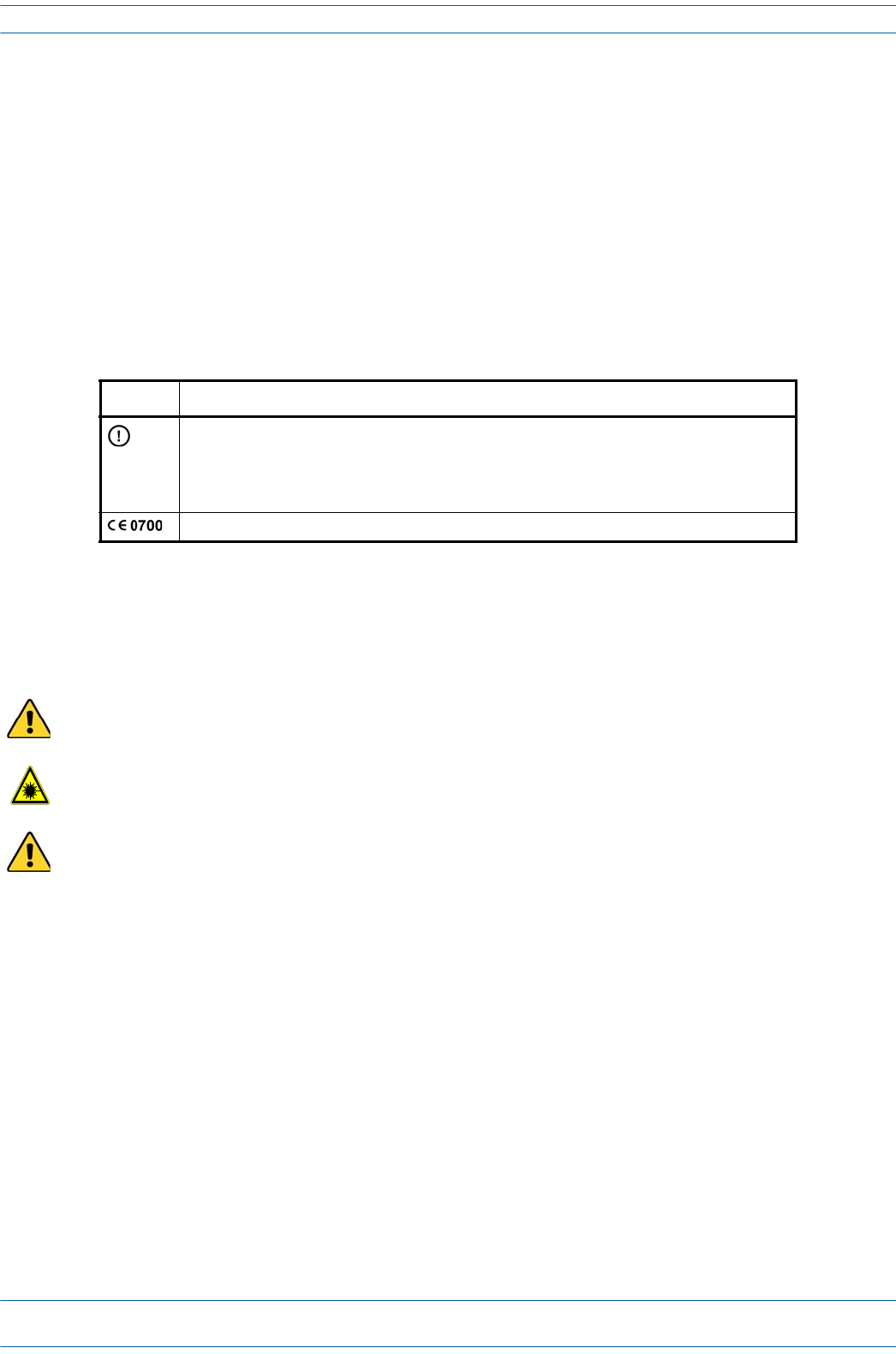
Table2-2identifiestheCEmarkingsusedonION-Ehardwareanddefineswhatthesemarkingsmean,
includingrequiredusercompliance.
Health and Safety Precautions
Observeallcautionsandwarningslistedinthissection
.
Table 2-2. CE Compliance Labels
Symbol Meaning
Alert sign to R&TTE
To be sold exclusively to mobile operators or authorized installers - no harmonised frequency
bands, operation requires license.
Intended use: EU and EFTA countries
Indicates conformity with the R&TTE directive 1999/5/EC certified by the notified body no. 0700.
A High leakage current ground (earth) connection to the Power Supply Subrack is essential before
connecting the supply.
Laser radiation. Risk of eye injury in operation. Do not stare into the laser beam; do not view the laser
beam directly or with optical instruments.
High frequency radiation in operation. Risk of health hazards associated with radiation from the
antenna(s) connected to the unit. Implement prevention measures to avoid the possibility of close
proximity to the antenna(s) while in operation.

ION®-E Series Hardware Installation Guide M0201AA
Page 10 © June 2017 CommScope, Inc.
Safely Working with ION-E Hardware
Property Damage Warnings
Due to power dissipation, the power supply units may reach a very high temperature if not properly
ventilated. Do not operate this equipment on or close to flammable materials.
ESD precautions must be observed. Before commencing maintenance work, use the available grounding
(earthing) methodology to connect ESD protection measures.
Keep operating instructions within easy reach and make them available to all users.
Only license holders for the respective frequency range are allowed to operate this unit.
Read and obey all the warning labels attached to the unit. Make sure that all warning labels are kept in a
legible condition. Replace any missing or damaged labels.
Make sure the unit's settings are correct for the intended use (refer to the manufacturer product
information) and regulatory requirements are met. Do not carry out any modifications or fit any spare
parts, which are not sold or recommended by the manufacturer.

M0201AA ION®-E Series Hardware Installation Guide
© June 2017 CommScope, Inc. Page 11
Compliance and Standards Certification
COMPLIANCE AND STANDARDS CERTIFICATION
FCC RF Exposure Requirements
Forinstallations,whichhavetocomplywithFCCRFexposurerequirements,theantennaselectionand
installationmustbecompletedinawaytoensurecompliancewiththoseFCCrequirements.Dependingon
theRFfrequency,ratedoutputpower,antennagain,andthelossbetweentherepeaterandantenna,the
minimumdistanceDtobemaintainedbetweentheantennalocationandhumanbeingsiscalculated
accordingtothisformula:
where
•P(mW)istheradiatedpowerattheantenna,i.e.themax.ratedrepeateroutputpowerinadditiontothe
antennagainminusthelossbetweentherepeaterandtheantenna.
•PD(mW/cm²)istheallowedPowerDensitylimitacc.to47CFR1.1310(B)forgeneralpopulation/
uncontrolledexposureswhichis
–f(MHz)/1500forfrequenciesfrom300MHzto1500MHz
–1forfrequenciesfrom1500MHzto100,000MHz
RFexposurecompliancemayneedtobeaddressedatthetimeoflicensing,asrequiredbytheresponsibleFCC
Bureau(s),includingantennaco-locationrequirementsof1.1307(b)(3).
EMC Standards
•ForinstallationsthathavetocomplywithEuropeanEN50385exposurecompliancerequirements,the
followingPowerDensitylimits/guidelines(W/m²)accordingtoICNIRParevalid:
–2forfrequenciesfrom10MHzto400MHz
–f(MHz)/200forfrequenciesfrom400MHzto2GHz
–10forfrequenciesfrom2GHzto300GHz
•ThisunitcomplieswithEuropeanstandardEN60950.
This is class A equipment. This equipment can cause radio interference in domestic areas. In this case the
operator can be asked to start preventive action.
]/[
][
][
2
4cmmW
mW
cm PD
P
D∗∗
=
π

ION®-E Series Hardware Installation Guide M0201AA
Page 12 © June 2017 CommScope, Inc.
Compliance and Standards Certification
FCC and IC Standards
Notice:ForinstallationsthathavetocomplywithFCC/IndustryCanadarequirements:
English
ThisdevicecomplieswithFCCPart15.Operationissubjecttothefollowingtwoconditions:(1)thisdevice
maynotcauseinterference,and(2)thisdevicemustacceptanyinterference,includinginterferencethatmay
causeundesiredoperationofthedevice.
ThisdevicecomplieswithHealthCanada'sSafetyCode.TheinstallerofthisdeviceshouldensurethatRF
radiationisnotemittedinexcessoftheHealthCanada'srequirement.Informationcanbeobtainedathttp:
//www.hc-sc.gc.ca/ewh-semt/pubs/radiation/radio_guide-lignes_direct-eng.php.
Changesormodificationsnotexpresslyapprovedbythepartyresponsibleforcompliancecouldvoidthe
user'sauthoritytooperatetheequipment.
Theantenna(s)usedforthistransmittermustbeinstalledtoprovideaseparationdistanceofatleast20cm
fromallpersonsandmustnotbeco-locatedoroperatinginconjunctionwithanyotherantennaor
transmitter.
French
CetappareilestconformeàFCCPartie15.SonutilisationestsoumiseàLesdeuxconditionssuivantes:(1)cet
appareilnepeutpasprovoquerd’interférenceset(2)cetappareildoitaccepterTouteinterférence,ycompris
lesinterférencesquipeuventcauserunmauvaisfonctionnementdudispositif.
CetappareilestconformeavecSantéCanadaCodedesécurité6.Leprogrammed’installationdecetappareil
doits’assurerquelesrayonnementsRFn’estpasémisau-delàdeI’exigencedeSantéCanada.Les
informationspeuventêtreobtenues:
http://www.hc-sc.gc.ca/ewh-semt/pubs/radiation/radio_guide-lignes_direct-fra.php
Leschangementsoumodificationsnonexpressémentapprouvésparlapartieresponsabledelaconformité
pourraientannulerl'autoritédel'utilisateuràutilisercetéquipement.
Laoulesantennesutiliséesaveccetémetteurdoiventêtreinstalléesavecuneséparationd’auminimum
20cmavectoutepersonneetnedoiventpasêtreco-localiséesouutiliséesavectouteautreantenneoutout
autreémetteur.
ForaClassAdigitaldeviceorperipheral.
ThisequipmenthasbeentestedandfoundtocomplywiththelimitsforaClassAdigitaldevice,pursuantto
EN55022andpart15oftheFCCRules.Theselimitsaredesignedtoprovidereasonableprotectionagainst
harmfulinterferencewhentheequipmentisoperatedinacommercialenvironment.
Thisequipmentgenerates,uses,andcanradiateradiofrequencyenergyand,ifnotinstalledandusedin
accordancewiththeinstructionmanual,maycauseharmfulinterferencetoradiocommunications.Operation
ofthisequipmentinaresidentialareaislikelytocauseharmfulinterferenceinwhichcasetheuserwillbe
requiredtocorrecttheinterferenceathisownexpense.

M0201AA ION®-E Series Hardware Installation Guide
© June 2017 CommScope, Inc. Page 13
Chapter Topics Page
WCS-2 and WCS-4 Subracks and Modules ..........................................................................................................................................................14
WCS Subrack Front Panel Card Slots and GUI Identification .......................................................................................................................... 15
WCS Subrack Back Panel Connectors .............................................................................................................................................................16
WCS Subrack Alarm Connector....................................................................................................................................................................... 17
WCS Fan Modules and Filters ......................................................................................................................................................................... 18
System User Interface Card (SUI) ................................................................................................................................................................... 19
RF Donor Card (RFD)....................................................................................................................................................................................... 20
Optical Transport Card (OPT).......................................................................................................................................................................... 21
Copper Transport Card (CAT).......................................................................................................................................................................... 22
Auxiliary Unit Transport Card (AUT) ............................................................................................................................................................... 23
Installing Subracks and PSUs in an Equipment Rack ........................................................................................................................................... 24
Rack-Mounting the Subracks and PSU............................................................................................................................................................24
Connect the Subrack and PSU Power and Communication Cables ................................................................................................................ 25
Install the CAN and TEN Cards........................................................................................................................................................................ 27
Install SFP+ Transceivers in the OPT Cards..................................................................................................................................................... 28
Connect the RFD Cards ................................................................................................................................................................................... 29
Connect the CAT Cards ................................................................................................................................................................................... 30
Connect the AUT Cards................................................................................................................................................................................... 32
ThischapterprovidesaproductoverviewandinstallationinstructionsfortheION-ESeriesWCS-2andWCS-4
Subracks.
WCS-2 AND WCS-4 SUBRACKS AND MODULES 3
ION®-E Series Hardware Installation Guide M0201AA
Page 14 © June 2017 CommScope, Inc.
WCS-2 and WCS-4 Subracks and Modules
WCS-2 AND WCS-4 SUBRACKS AND MODULES
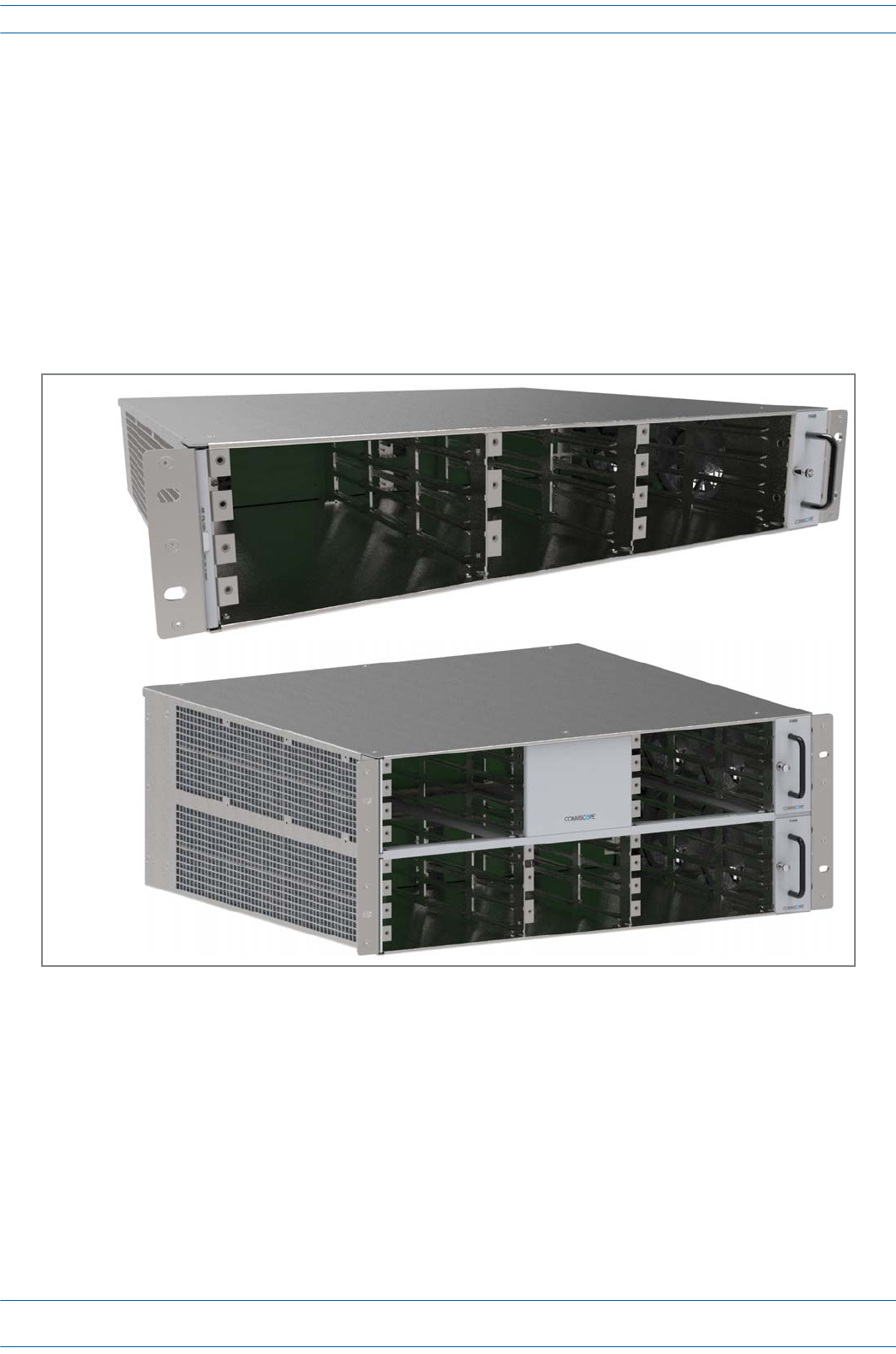
ThissectionprovidesinformationontheWCS-4andWCS-2Subracks(Figure3-1),whichdependentontheir
configuration,becomeaCentralAreaNodes(CAN)oraTransportExpansionNodes(TEN).
•TheCANistheserver-levelcontrolandprimarysignaldistributionwithinanION-Esystem.
•TheTENisthesecondarydistributionpointthatconnectstoaCANusingMulti-ModeorSingle-Mode
fiber.
•TheWCS-4isfourRack-Units(RUs)high,andistypicallyusedasaCAN,butcanalsoserveasaTEN.
•TheWCS-2istwoRUshigh,andistypicallyusedasaTEN,butcanalsoserveasaCAN.
Figure 3-1. WCS-2 and WCS-4 Subracks
WCS-2
Subrack
WCS-4
Subrack
M0201AA ION®-E Series Hardware Installation Guide
© June 2017 CommScope, Inc. Page 15
WCS-2 and WCS-4 Subracks and Modules
WCS Subrack Front Panel Card Slots and GUI Identification
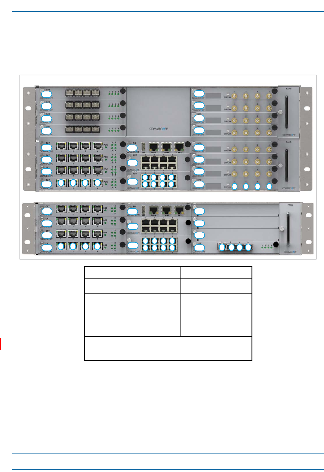
Thefollowinggraphicandtabledescribetheslotsinwhicheachcardshouldbeinstalled.Notethataportis
identifiedasadecimalpointaftertheslotlabel.Forexample,aCATCardinstalledinslotL1wouldhavefour
ports:L1.1,L1.2,L1.3,andL1.4.
Install this Card … … in this Slot
Optical Transport Card (OPT) CAT TEN
L1 - L8 R1
Copper Transport Card (CAT) L1 - L4 1
System User Interface Card (SUI) M3
Auxiliary Unit Transport Card (AUT) M1 - M2
RF Donor Card (RFD) CAT TEN
R1 - R8 N/A 2
1 Remote Power for UAPs and CAP Ls over Cat6A only available in slots
L1 - L4.
2 WCS Subracks configured as TENs do not currently support RFD Cards.
WCS-2 Subrack
L4
L3
L2
L1
M3
M2
M1
12 3 4
5
1
6
2
7
3
8
4123
R4
R3
R2
R1 4
L4
L3
L2
L1
M3
M2
M1
WCS-4 Subrack
12 3 4
5
1
6
2
7
3
8
4
L8
L7
L6
L5
R8
R7
R6
R5
R4
R3
R2
R1 1234
ION®-E Series Hardware Installation Guide M0201AA
Page 16 © June 2017 CommScope, Inc.
WCS-2 and WCS-4 Subracks and Modules
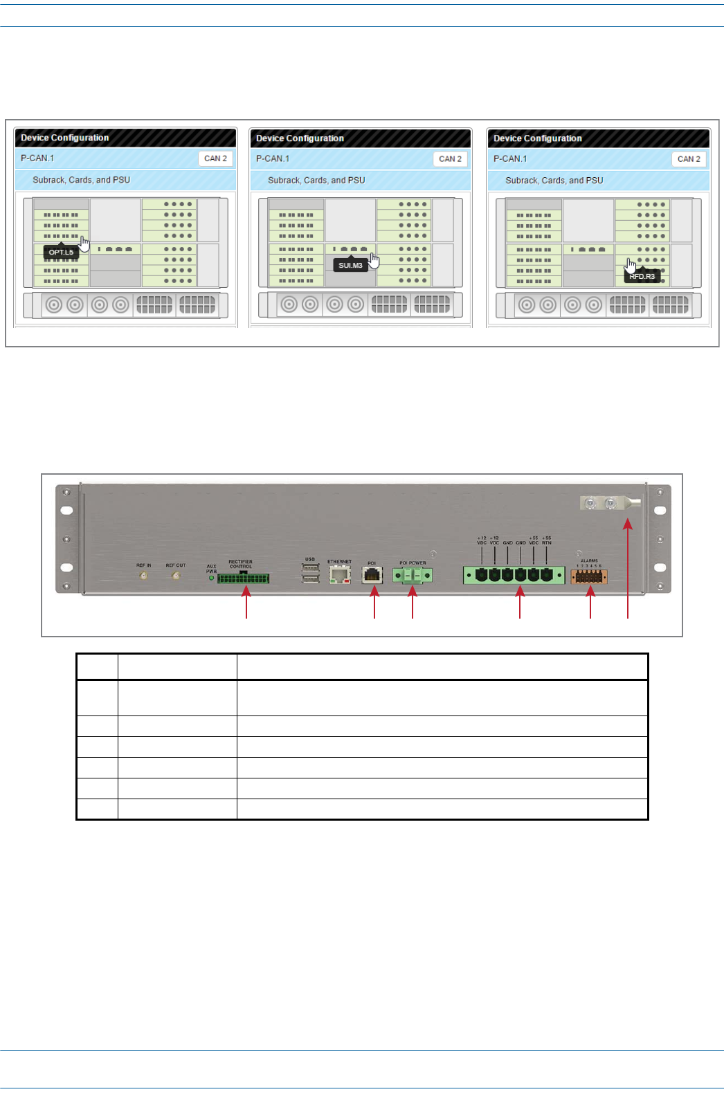
Thealphanumericnumberingoftheslotsandportscorrespondtotheslotandportidentificationusedinthe
ION-EGUI,asshowninFigure3-2.
Figure 3-2. Slot and Port Designations in the ION-E GUI
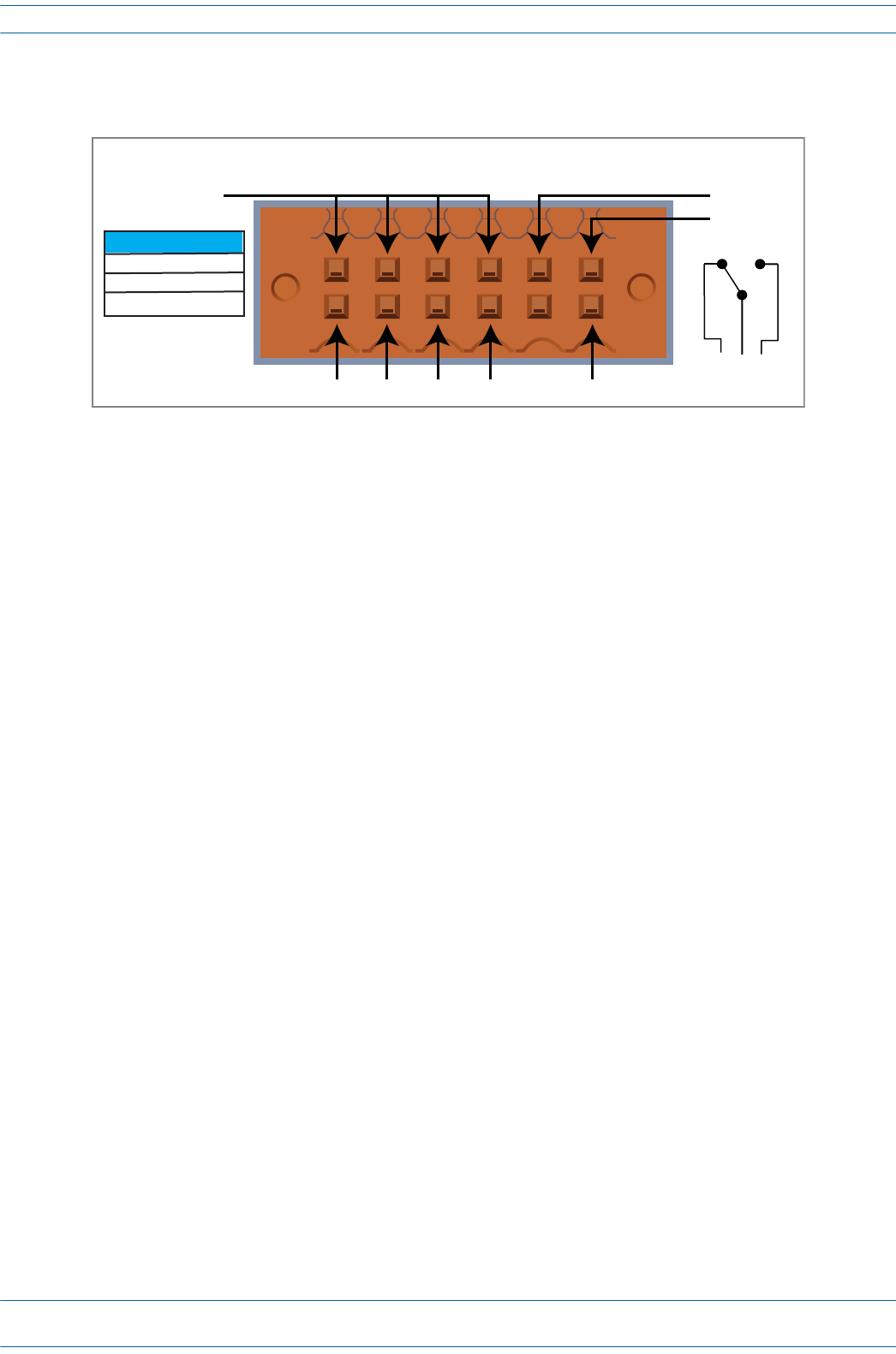
WCS Subrack Back Panel Connectors
UNRESOLVED: This looks like it is the rear of the WCS-2. Are the connectors laid out the same on WCS-4?
Ref. # Component Description
1 Rectifier Control
connector 24-pin connector for PSU communication
2 POI connector POI Communication
3 POI Power connector 12 Vdc to e-POI Subrack
4 Power connector Inputs to the 12 Vdc Module and the 57 Vdc Module
5 Alarm connector Dry contact input and output; see "WCS Subrack Alarm Connector” on page 17.
6 Ground stud Ground (earth) connection to the Power Supply Subrack
OPT Card in Slot L5 SUI Card in Slot M3 RFD Card in Slot R3
123456
M0201AA ION®-E Series Hardware Installation Guide
© June 2017 CommScope, Inc. Page 17
WCS-2 and WCS-4 Subracks and Modules
WCS Subrack Alarm Connector
TheAlarmconnectoronthebackpaneloftheWCS-4andWCS-2subrackshas
•fouropto-isolated(chassis-groundreferenced)drycontactinputstomonitorexternaldevices
•oneSummaryAlarmRelaythatenergizeswhenspecificalarmsaretriggered—thethresholdsofwhich
areshownintheprecedinggraphic.[Which alarms? We need to match the Summary Alarms shown above with
the actual corresponding alarms.]
NC COM NO
ALARMS
12345 6 Relay COM
GND
IN 1 IN 2 IN 3 IN 4 Relay NO
Relay NC
Summary Alarm
2 A max
30 Vdc max
125 Vac max
ION®-E Series Hardware Installation Guide M0201AA
Page 18 © June 2017 CommScope, Inc.
WCS-2 and WCS-4 Subracks and Modules
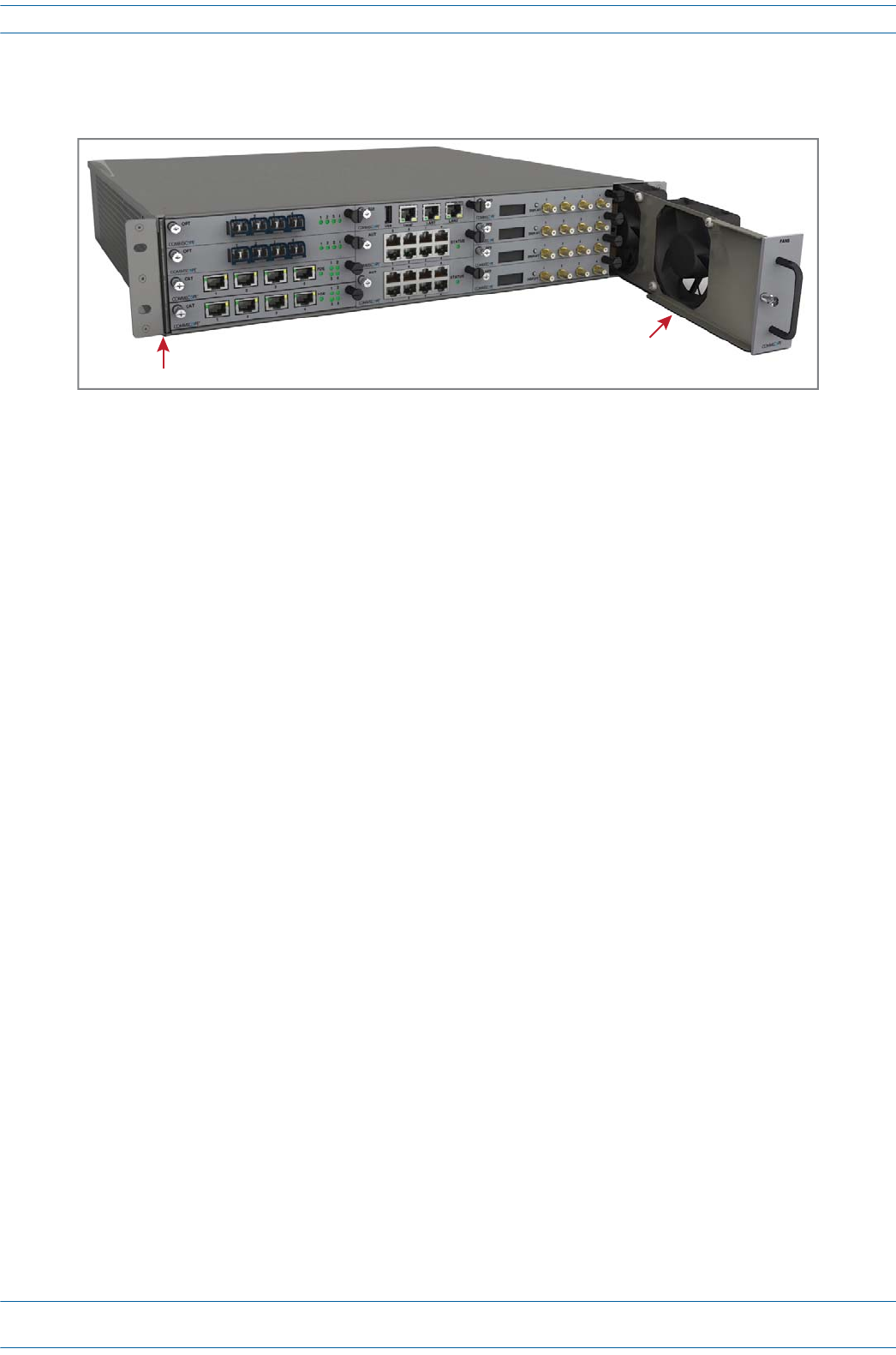
WCS Fan Modules and Filters
ThefollowingrulesapplytotheWCSFanModulesandFilters:
•FanModulesandFiltersmustbeinstalledforWCSoperation,buttheycanbereplacedwithoutsystem
interruption.
•FiltersareinsertedontheleftsideoftheWCS;twofiltersarerequiredforaWCS-4.
•FanModules(areinsertedontherightsideoftheWCSchassis;twoFanModulesarerequiredforaWCS-4.
Filter
Fan Module
M0201AA ION®-E Series Hardware Installation Guide
© June 2017 CommScope, Inc. Page 19
WCS-2 and WCS-4 Subracks and Modules
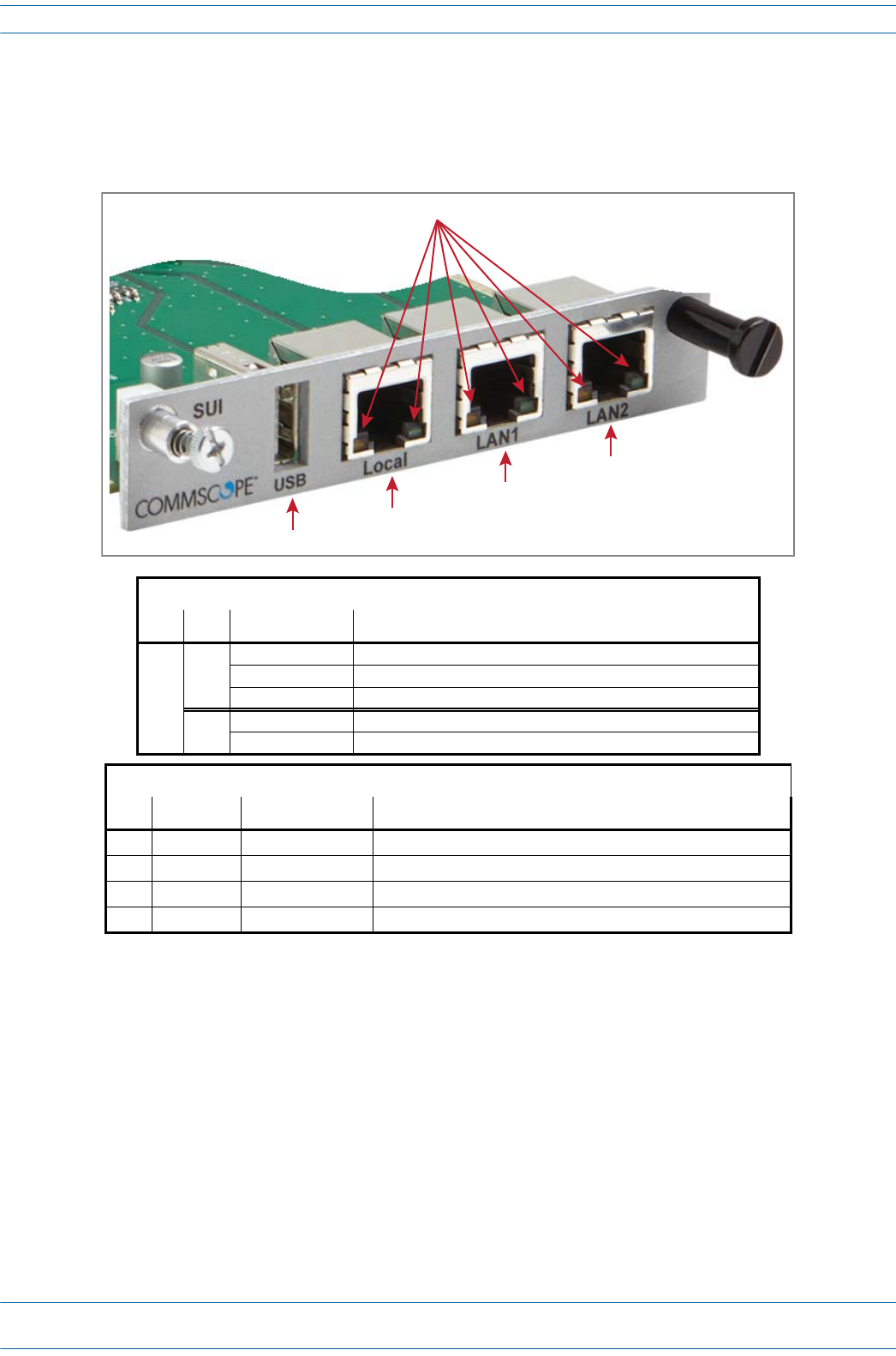
System User Interface Card (SUI)
TheSUIprovideslocalandLANEthernetconnectionsandaUSBport.YouinstallaSUICardinSlotM3ofthe
WCS-2orWCS-4Subrack.
SIU Card LEDs
Ref # LED LED Color Description
1
Left • Off • No link.
• Green • Link established with device to which the port is connected.
• Flashing green • Activity is occurring on that port.
Right • Off • 10 Mb connection established.
• Yellow • 100 Mb connection established.
SIU Card Connectors
Ref # Component Device Function
2USB port 2.0 USB Connects to a a local laptop to allow the transfer of files.
3Local port Connects to a local laptop; fixed IP address.
4LAN1 port RJ-45 jack (female) Reserved for future use.
5LAN2 port RJ-45 jack (female) Connects to a LAN or modem; DHCP or specified fixed IP address
2
3
4
5
1
ION®-E Series Hardware Installation Guide M0201AA
Page 20 © June 2017 CommScope, Inc.
WCS-2 and WCS-4 Subracks and Modules
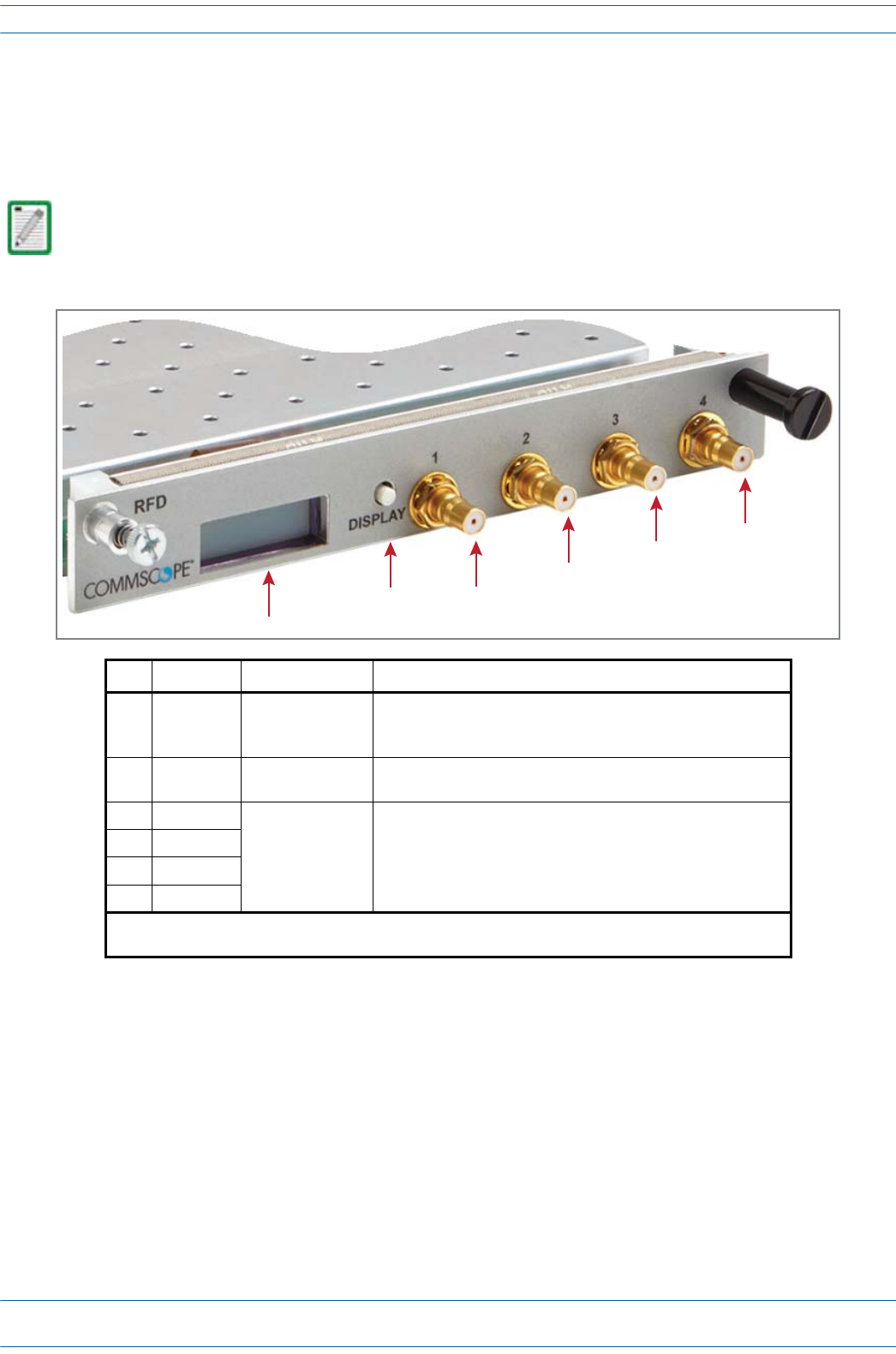
RF Donor Card (RFD)
TheRFDistheinterfaceforRFsignalsbetweentheCANandtheBTSoreNode-B.YouinstallRFDCardsin
SlotsR1-R8ofaWCS-2orWCS-4SubrackthatisconfiguredasaCAN.
TENs do not support the use of RFD Cards.
Ref # Component Device Function
1Display LCD • The first line of the display shows the port number and band.
• The second line of the display shows the service provider or
multiple if multiple providers are connected to the port.
2Display
button Push button Push once to turn on the display backlight, and then push four
more times to cycle through the four ports.
3Port 1 1
Female QMA
connector (shown
populated)
Connect to the UL/DP Ports 1 - 4 on an e-POI Module.
• RF Paths: simultaneous transmit and receive.
• Protection: relays with adjustable trip threshold.
• Frequency: 380 - 2700 MHz
4Port 2 1
5Port 3 1
6Port 4 1
1 Path 1 and Path 2 of an LTE MIMO BTS must be connected to either Ports 1 and 2 of the RFD Card as a
pair, or to Ports 3 and 4 as a pair.
2
1
3
4
5
6
M0201AA ION®-E Series Hardware Installation Guide
© June 2017 CommScope, Inc. Page 21
WCS-2 and WCS-4 Subracks and Modules
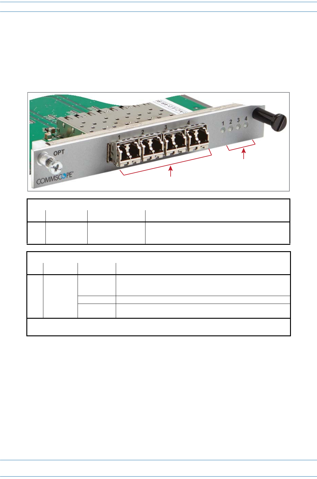
Optical Transport Card (OPT)
TheOPTprovidesa10GbfiberconnectionbetweenaCANandaTEN.WhereyouinstallanOPTCardina
WCS-2orWCS-4SubrackisdependentwhetherthesubrackisconfiguredasaCANoraTEN:
•CAN—SlotL1-L8.
•TEN—SlotR1only,andtheSFP+transceivermustbeinstalledintheOPTSFPPort1.
OPT Card SFP Connectors
Ref # Component Device Function
11 - 4 10 Gbps SFP port for
Multi-Mode or
Single-Mode fiber
Support for up to four SFP+ transceivers; each SFP port provides
high-speed fiber connections between a CAN and a TEN.
OPT Card SFP Port LEDs 1, 2
Ref # LED LED Color Description
21 - 4 • Off • The OPT Card has no power, or the OPT Card is plugged into the wrong
subrack slot (see "WCS Subrack Front Panel Card Slots and GUI
Identification” on page 15).
• Green • Optical link is established with device to which the port is connected.
• Yellow • The OPT Card is powered and initialized, but the link with the
corresponding SFP port is not established.
1 SFP Port LED numbers correspond with the SFP port numbers.
2 When the OPT Card is installed in a TEN, only SFP Port LED 1 is functional.
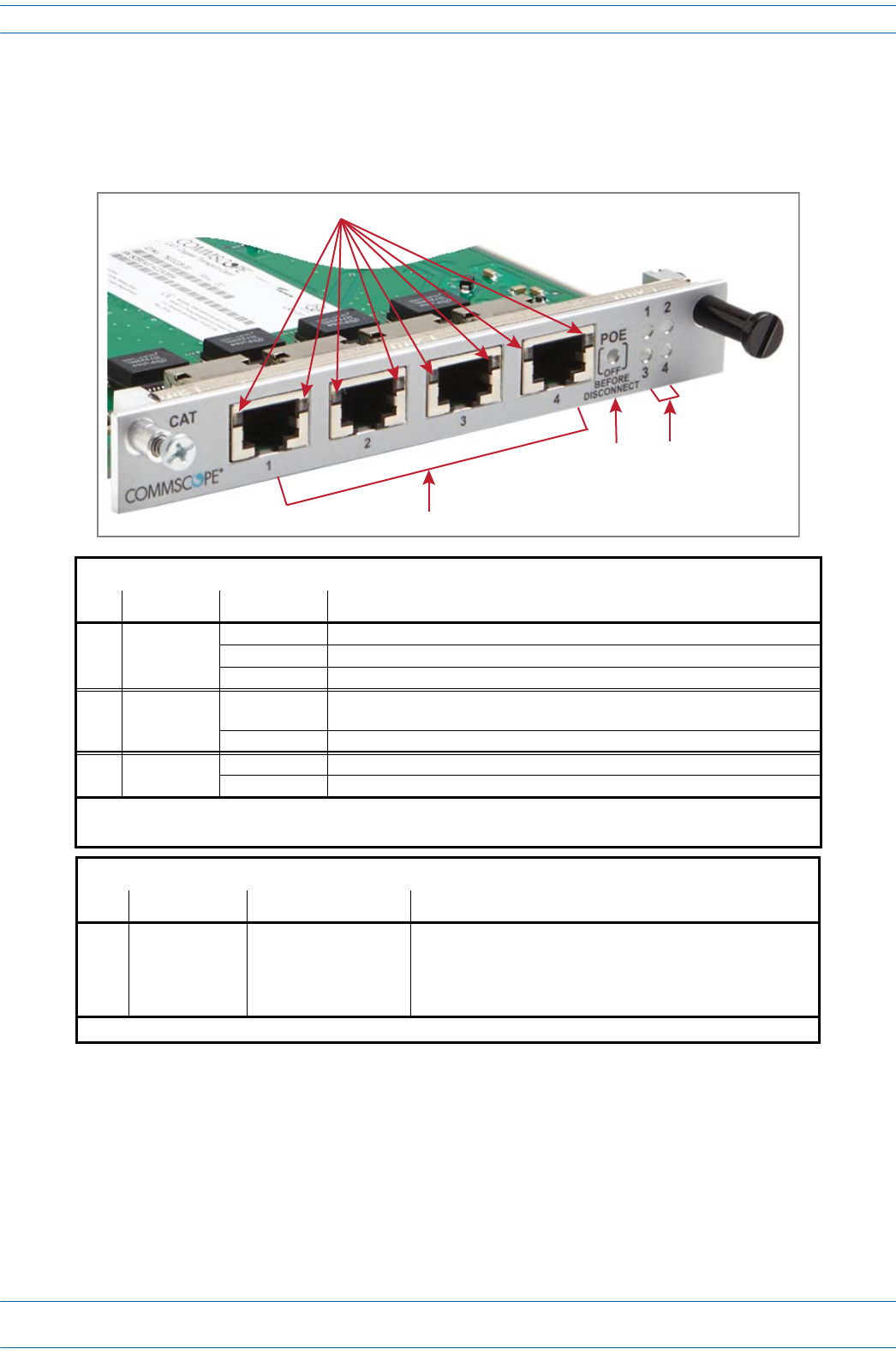
1
2
ION®-E Series Hardware Installation Guide M0201AA
Page 22 © June 2017 CommScope, Inc.
WCS-2 and WCS-4 Subracks and Modules
Copper Transport Card (CAT)
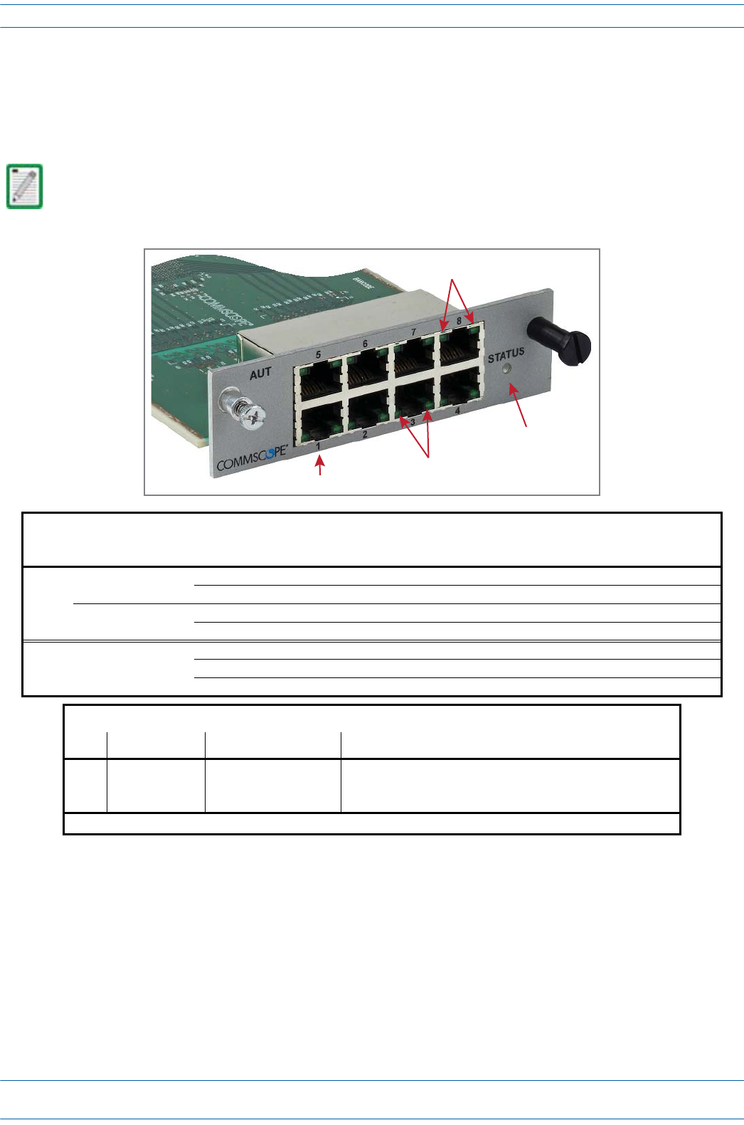
TheCATCardprovidespowerand10GbpsdataoverCat6AcablestoUAPs.YouinstallaCATCardinSlots
L1-L4oftheWCS-2orWCS-4Subrack.
CAT Card LEDs
Ref # LED LED Color Description
1 RJ45 1 - 4 • Off • No link between the CAT Card and the UAP1 to which the port is connected.
• Green • Indicates that a 10G link is established.
• Yellow • Indicates that a 1G link is established.2
3 POE •Off •Power over Cat6A between the CAT Card and the UAP has not been
established.
•Green •Power over Cat6A established between the CAT Card and the UAP.
4 Port • Off • No power to the subrack.
•Red •Active fault on that link.
1 Unless otherwise noted, the use of “UAP” collectively refers to the UAP, UAP-X, UAP-N25, and the CAP L.
2 1G link is not currently supported.
CAT Card Connectors
Ref # Component Device Function
2 Port 1 - 4 RJ45, Cat6A Connects the CAN/TEN to UAPs over Cat6A cables.1
• Each CAT Card can support a maximum of six UAPs.
• A CAN/TEN with four CAT cards installed can support up to
twenty-four UAPs.
1 Unless otherwise noted, the use of “UAP” collectively refers to the UAP, UAP-X, UAP-N25, and the CAP L.
2
1
34
M0201AA ION®-E Series Hardware Installation Guide
© June 2017 CommScope, Inc. Page 23
WCS-2 and WCS-4 Subracks and Modules
Auxiliary Unit Transport Card (AUT)
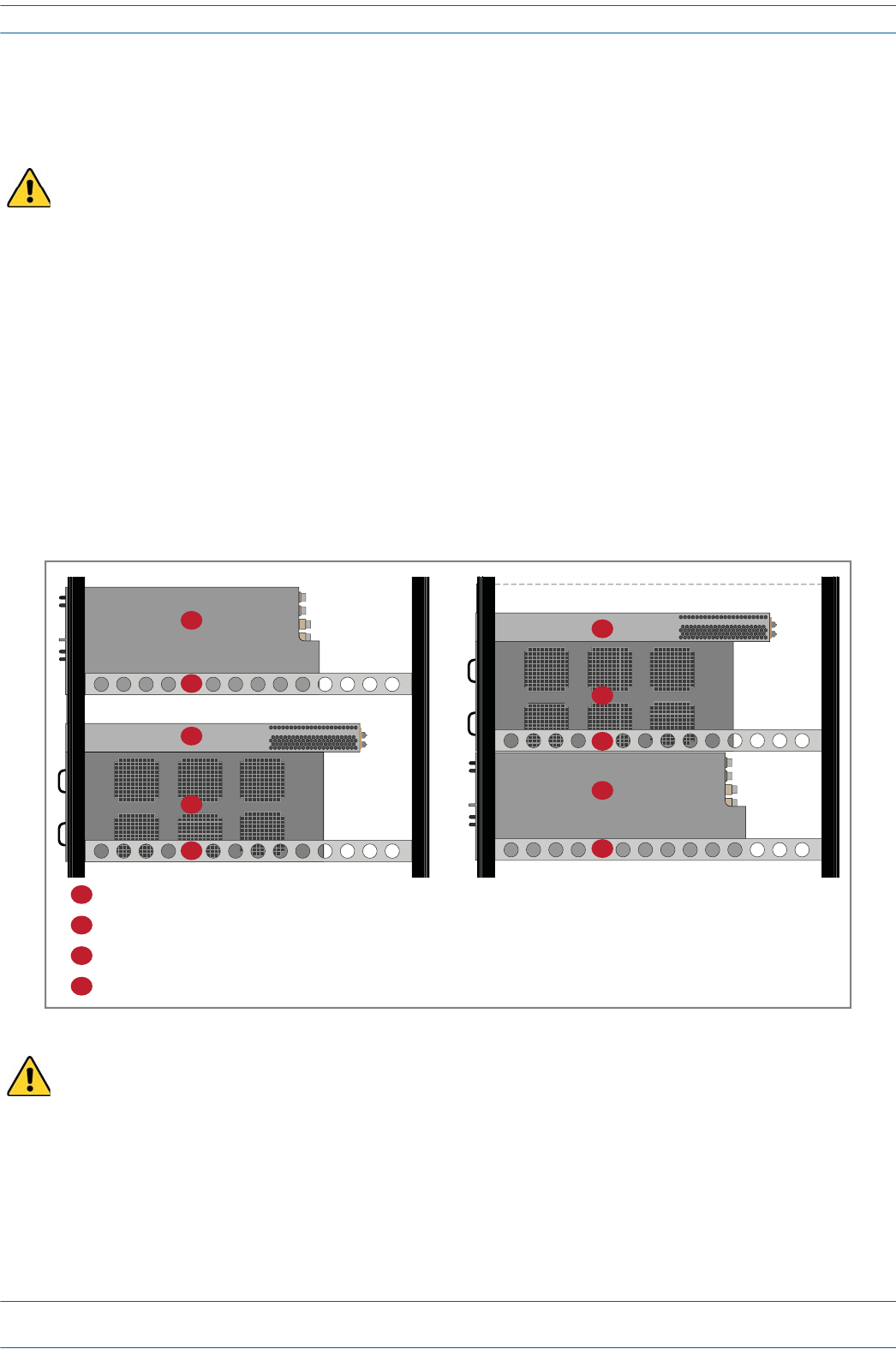
TheAUTCardprovidesa1Gbpass-throughconnectionbetweentheCAN/TENandtheUAPforWiFi,IP
cameras,orother1GbEthernetdevices.YouinstallanAUTCardinSlotM1orM2oftheWCS-2orWCS-4
Subrack.
UNRESOLVED: The RJ45 ports are reversed top (5 - 6) vs. bottom (1 - 4). Are the LEDs the same regardless
of vertical orientation of plug, or are the LEDs also reversed (top left is bottom right)?
UNRESOLVED: If the Right LED is green, to know if it means 100 Mbit/s vs. not connected, to be not
connected, wouldn’t the Left LED be off?
UNRESOLVED: Confirm Gbps can replace Gbit/s and Mbps = Mbit/s
For information on the internal mapping between CAT Cards and AUT Cards, go to "Connect the AUT
Cards” on page 32.
AUT Card LEDs
Ref # LED LED Color Description
2Left LED
on RJ45 Ports 1 - 8
• Off • No activity on that port.
• Flashing green • Activity on that port.
Right LED
on RJ45 Ports 1 - 8
• Off • Port is transmitting 1 Gbps.
• Green • Port is transmitting 100 Mbps or is not connected (Left LED will be off).
3 STATUS • Off • Error on the AUT Card, or AUT Card is not receiving power.
•Green •AUT Card functioning as expected.
• Red • AUT Card is experiencing an error.
AUT Card Connectors
Ref # Component Device Function
1 Ports 1 - 8 RJ45 ports Connects the CAN/TEN to WiFi, IP Camera, or other 1Gb
Ethernet devices; provides the 1Gb pass-through connection
between the CAN/TEN and the UAP.1
1 Unless otherwise noted, the use of “UAP” collectively refers to the UAP, UAP-X, UAP-N25, and the CAP L.
1
2
3
2
ION®-E Series Hardware Installation Guide M0201AA
Page 24 © June 2017 CommScope, Inc.
Installing Subracks and PSUs in an Equipment Rack
INSTALLING SUBRACKS AND PSUS IN AN EQUIPMENT RACK
ThefollowingsectionstellhowtoinstallION-EWCSande-POIsubracksandthePSUinanequipmentrack.
Rack-Mounting the Subracks and PSU
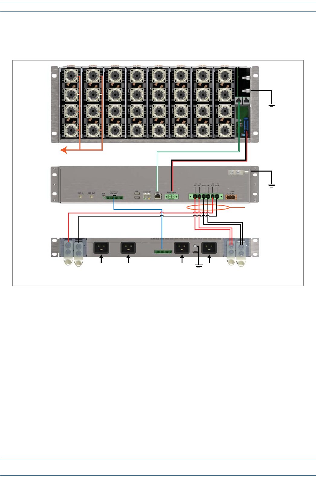
ThefollowinggraphicshowstwoconfigurationsformountingION-EsubracksandPSUsinanequipment
rack.InanyION-Einstallation,thefollowingrulesmustbefollowed:
•PSUsmustbemountedabovetheWCSforsupport.
•1RUofairspacerequiredabovethePSU.
•SupportrailsarerequiredforWCSSubracks.
•Supportrailsarerequiredfore-POISubracks.
•Supportrailsmustnotblockairflow.
As with any piece of IT equipment, placing the ION-E system connection behind a secure firewall is highly
recommended
Disconnect all input to the PSU before adding it to or removing it from an equipment rack.
1 RU air space required
4
1
2
2
3
1 RU air space required
1
2
3
2
4
1e-POI Subrack (4RU high)
2Support rail
3Power Supply Unit (PSU)
4WCS Subrack (WCS-2 is 2 RU high and WCS-4 is 4RU high)
M0201AA ION®-E Series Hardware Installation Guide
© June 2017 CommScope, Inc. Page 25
Installing Subracks and PSUs in an Equipment Rack
Connect the Subrack and PSU Power and Communication Cables
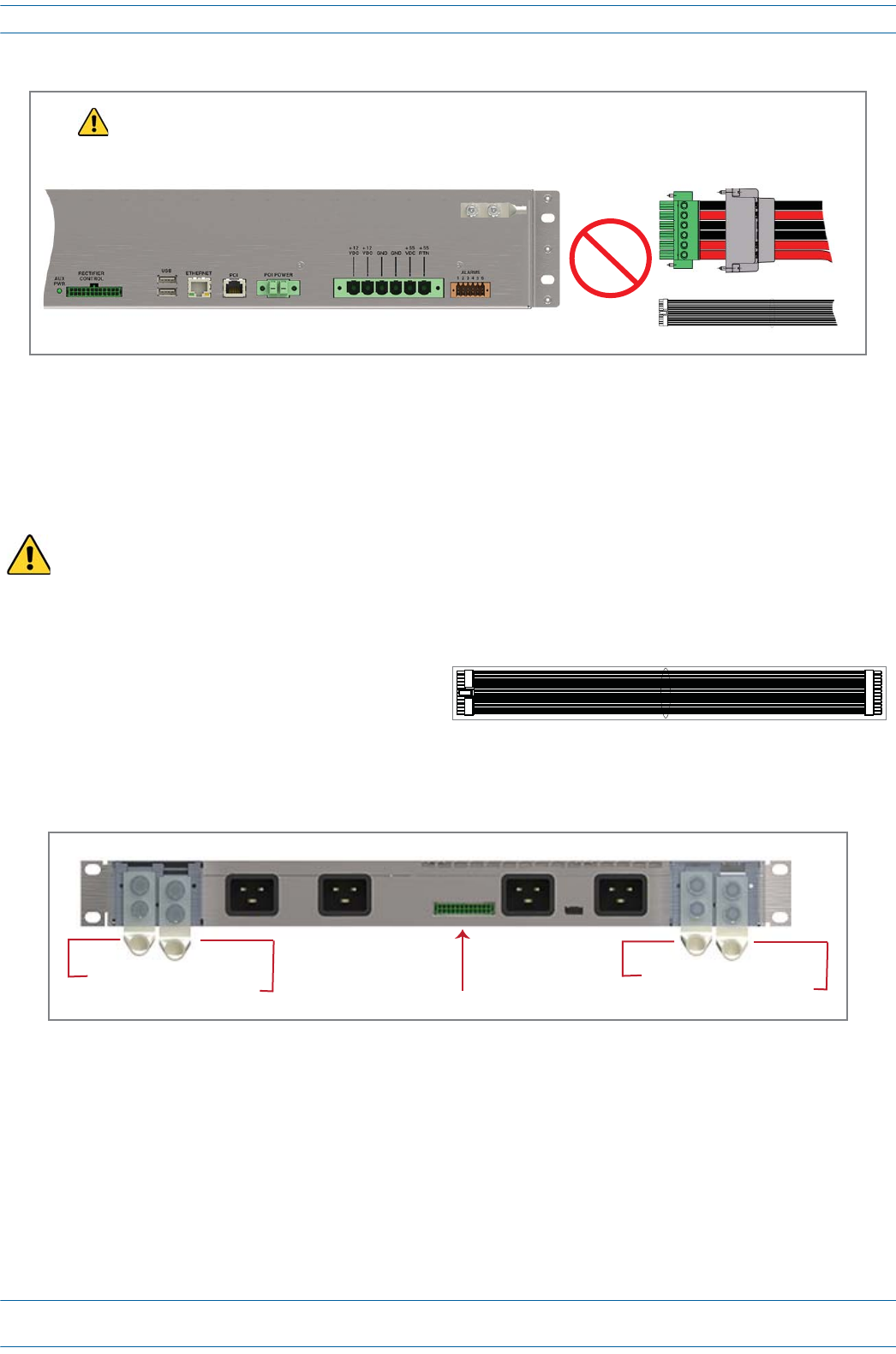
1Connecttherear-panelpower,communication,andcontrolcablesasshowninthefollowinggraphic.
e-POI
WCS
PSU
To/From eNodeB e-POI communicaons e-POI power
Subrack ground
(required)
WCS DC power
Subrack ground
(required)
Recfier control
Subrack ground
(required)
85 to 264 Vac
ION®-E Series Hardware Installation Guide M0201AA
Page 26 © June 2017 CommScope, Inc.
Installing Subracks and PSUs in an Equipment Rack
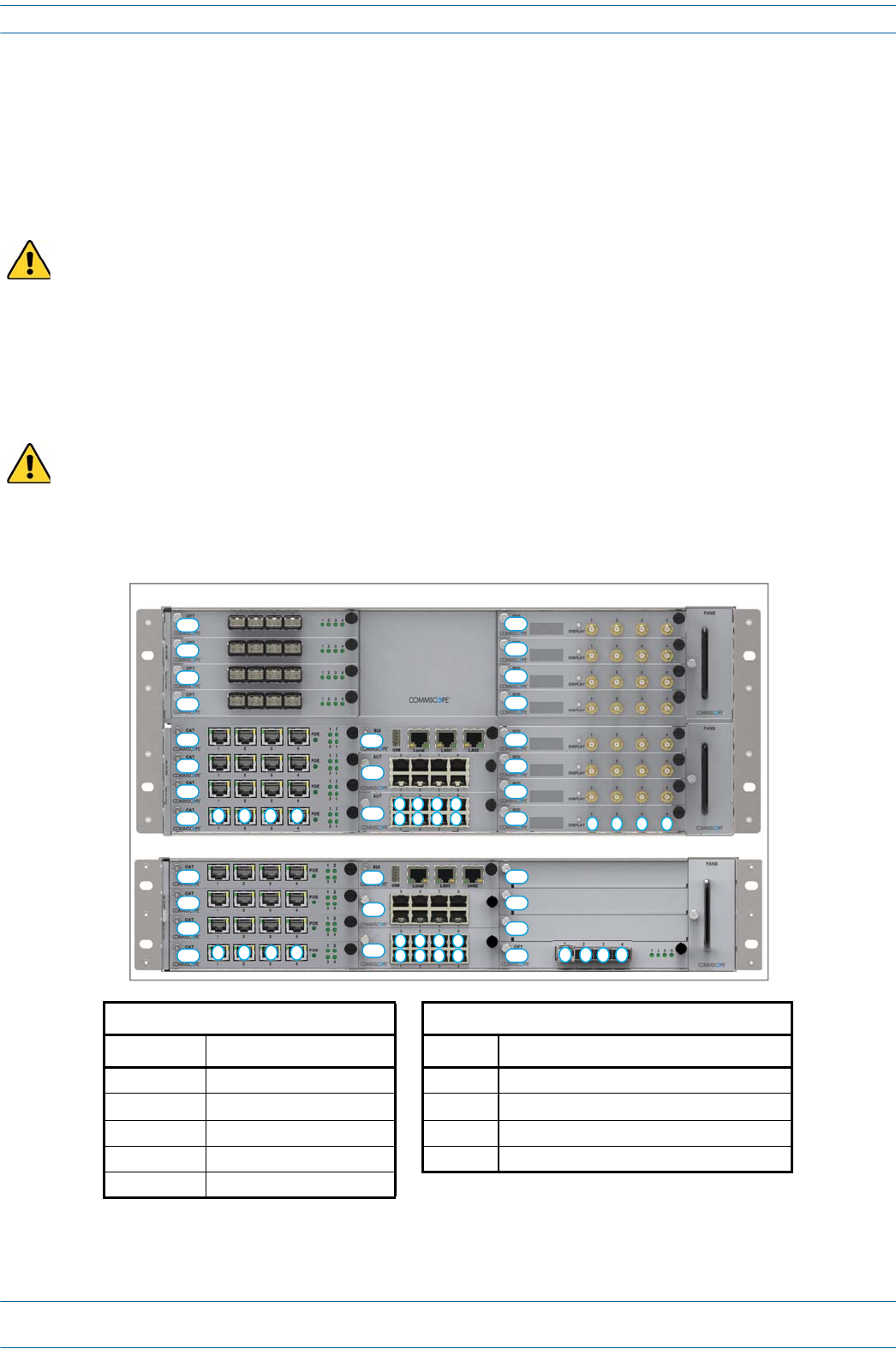
2ConnecttheDCPowercableandtheRectifierControlcables.
aDooneofthefollowingbeforeconnectingtheWCSPSUCableortheRectifierControlCable:
•ConfirmthatallACpowercablesareunpluggedfromtherearofthePSU.
•Remove12VdcPowerModulesand57VdcPowerModulesfromthePSU.
bPlugtheDCpowercableconnector,whichisattachedtotherearofthePSU,intotheWCSSubrack
powerconnector,andthenuseaflat-bladescrewdrivertotightenthetwomountingscrews.
cSlidethePowerConnectorshelloverthesubrackpowerconnectorandtightenthetwothumbscrews
toattachittotheWCSSubrack.
dPlugtheRectifierControlCable(shownto
theright)intotheWCSRectifierControl
connector;pressitinuntilyouhearitclick
andlockintoplace.
ePlugtheotherendoftheRectifierControlCabletothematchingconnector(unlabeled)ontherearof
thePSU.
3ConnecttheGroundstudontheWCS,PSU,ande-POIsubrackstoasuitableground(earth)accordingto
localandnationalelectricalcodes.
To prevent damage to the WCS, make sure you the two mounting screws have been tightened enough that
the DC Power cable is secure and cannot be accidentally dislodged.
WCS PSU Cable
Recfier Control Cable
To prevent SEVERE damage to the WCS Subrack, confirm that all AC power cables
are unplugged from the rear of the PSU BEFORE plugging/unplugging the
WCS Power or Recfier Control cables into/from the WCS subrack.
CAUTION!
Rear Panel of PSU
+57 Vdc Power terminal
- 57 Vdc Power terminal Recfier Control connector
+12 Vdc Power terminal
- 12 Vdc Power terminal
M0201AA ION®-E Series Hardware Installation Guide
© June 2017 CommScope, Inc. Page 27
Installing Subracks and PSUs in an Equipment Rack
Install the CAN and TEN Cards
1Ifnecessary,removetheblankfaceplate(s)fromtheslot(s)inwhichtheDARTistobeinstalled.
aLoosenthetwothumbscrewsthatsecuretheblankfaceplate(s)totheHostUnitchassis.
bCarefullywithdrawtheblankDARTfaceplatefromthechassis.
cReservetheblankfaceplatesforfutureuse.
2Slidethecardintotheslotthatitwilloccupy,andthenpushitbackuntilitsfaceplateisflushagainstthe
subrackchassis.
3Tightenthetwothumbscrewsthatsecurethecardinthesubrackchassis.
4Donotleaveanyunoccupiedslotsopen;replaceblankfaceplates,asnecessary..
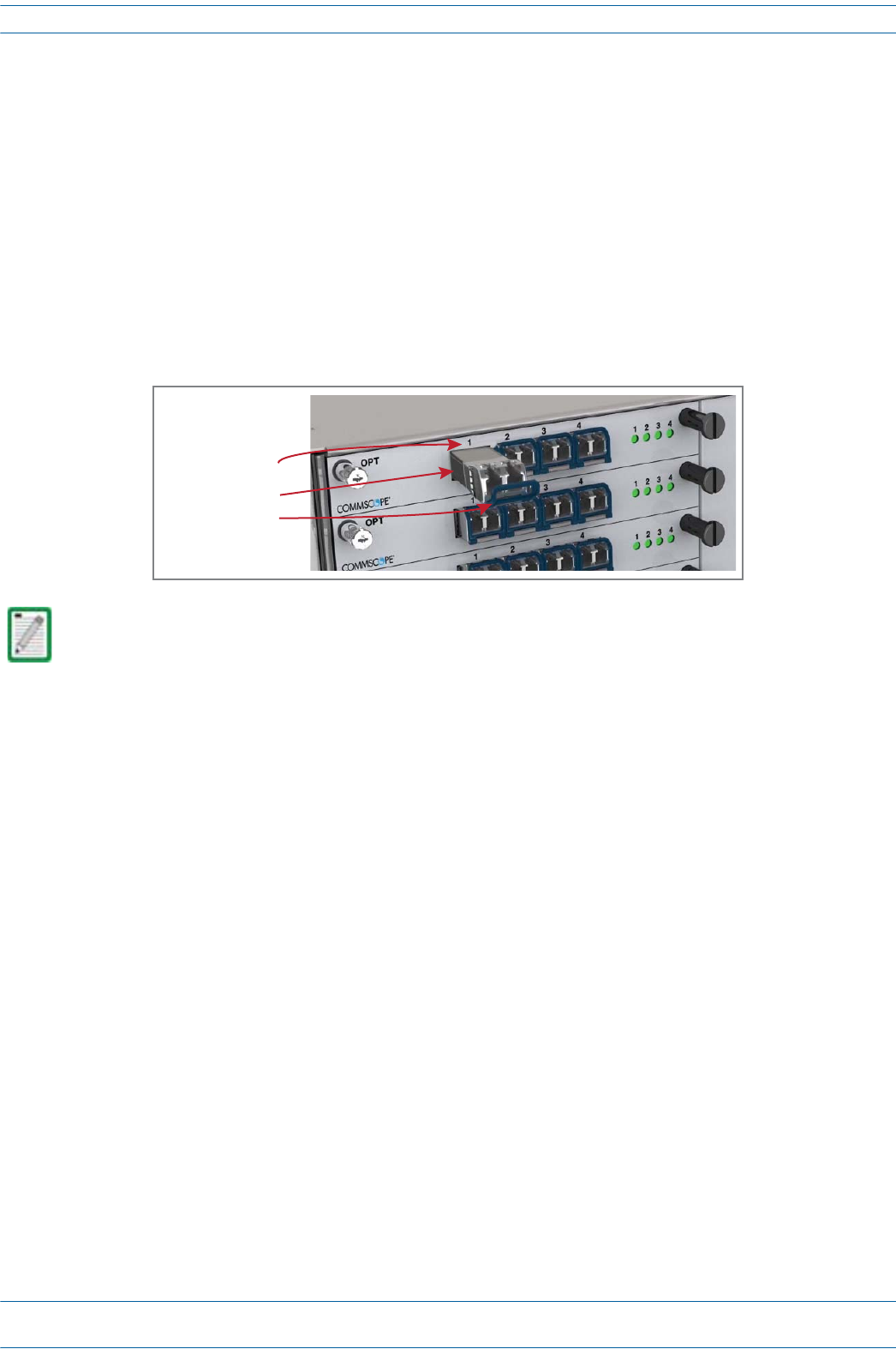
5FollowtheruleslistedbelowtoinstalltheCANandTENcardsintotheWCS-2orWCS-4Subrack.
Do not remove the blank faceplate from a slot in which a card will not be installed. To maximize airflow
through the WCS chassis, blank panels must be installed in all empty Card slots.
To maximize airflow through the WCS chassis, blank panels must be installed in all empty Card slots. If
additional blank faceplates are required, you can order them from CommScope (see "Contacting DCCS
Global Technical Support” on page 126).
Placement of cards to create a CAN Placement of cards to create a TEN 2
Card Slot Install this Card Card Slot Install this Card
L5 - L8 OPT Card R1 OPT Card; use Port 1 to connect to the CAN
L1 - L4 1 CAT Card L1 - L4 CAT Card
R1 - R8 RFD Card M3 SUI Card
M3 SUI Card M1 - M2 AUT Card (optional)
M1 - M2 AUT Card (optional)
1 Can also be used for additional OPT
Cards.
2 TENs do not support RFD Cards.
WCS-2 Subrack
L4
L3
L2
L1
M3
M2
M1
12 3 4
5
1
6
2
7
3
8
4123
R4
R3
R2
R1 4
L4
L3
L2
L1
M3
M2
M1
WCS-4 Subrack
12 3 4
5
1
6
2
7
3
8
4
L8
L7
L6
L5
R8
R7
R6
R5
R4
R3
R2
R1 12 3 4
ION®-E Series Hardware Installation Guide M0201AA
Page 28 © June 2017 CommScope, Inc.
Installing Subracks and PSUs in an Equipment Rack
Install SFP+ Transceivers in the OPT Cards
1Followthestepsin"InstalltheCANandTENCards”onpage27toinstalltheOPTCardintotheWCS
Subrack,asneededforthisinstallation:
•CAT:SlotsL1-L8
•TEN:SlotR1
2UsethesystemdesigntoidentifywhichOPTCardportswillbeusedinthissystem.
3ObtaintherequirednumberofSFP+Transceivers.
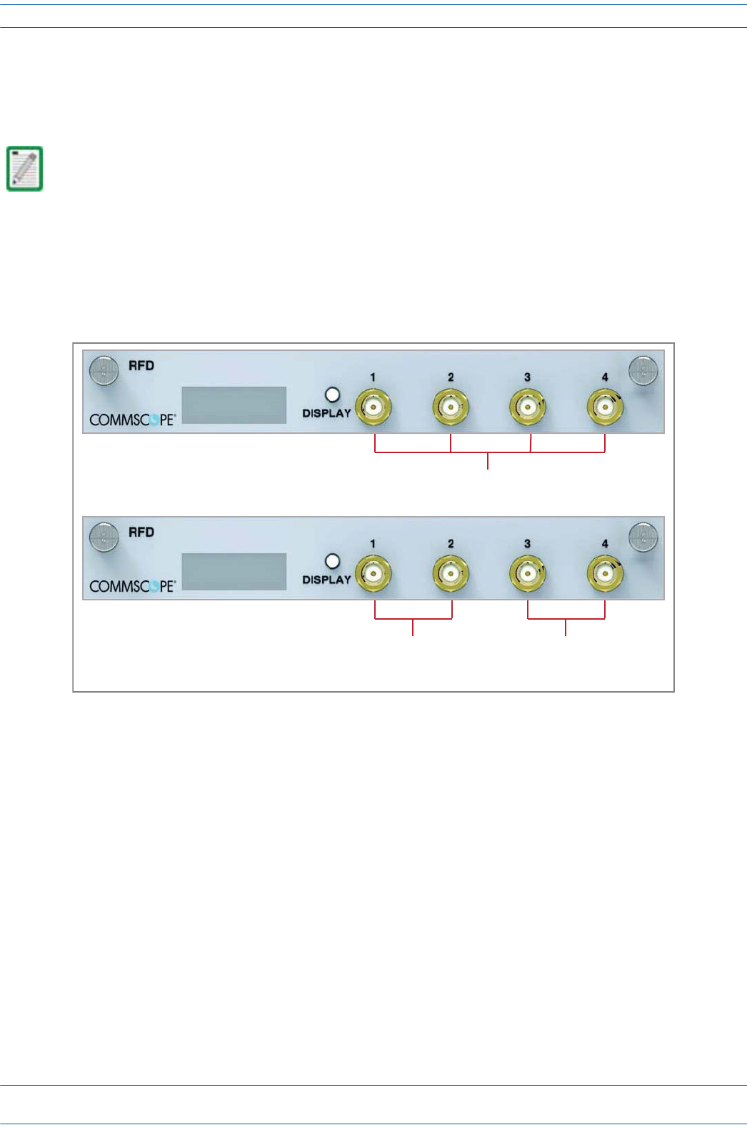
4SlidetheSFPintotheOPTCardportidentifiedinStep2,andpushtheSFPintotheOptCarduntilyouhear
itclickintoplace.
UNRESOLVED: Connect to what? R1.1 to CAN - otherwise? Cable?
Should you need to remove an SFP+ Transceiver, press down on its extraction lever, and then carefully pull
the transceiver out of the slot.
SFP+ Transceiver
Extracon lever
OPT Card Port 1
M0201AA ION®-E Series Hardware Installation Guide
© June 2017 CommScope, Inc. Page 29
Installing Subracks and PSUs in an Equipment Rack
Connect the RFD Cards
1Followthestepsin"InstalltheCANandTENCards”onpage27toinstalltheRFDCardsintotheWCS
SubrackSlotsR1-R8,asneededforaCANconfiguration.
2ConnectRFcablesfromtheBTS/eNodeBore-POItotheduplexQMAconnectorsoftheRFDcards.
•SISOservicessuchasCDMA,UMTS,GSM,andLTESISOcanbeconnectedtoanyactiveport.
•LTEMIMOpairsmustbeconnectedonthesameRFDCard,asapairto:Port1andPort2ortoPort3
andPort4.
3IfthesignallevelsoftheBTSexceedthemaximuminputlevelof+27dBm,ane-POIRFcardorother
suitableattenuatormustbeusedtoattenuatethesignal.ForoptimumPIMperformance,thecomposite
levelintoaDonor(RFDCard)portshouldbelessthan16dBm.Ifonlyonecarrierisinaband,PIMis
probablynotaconcern.Forthecaseoftwoormorecarriersinaband,spuriousintermodsduetoPIM
couldlandintheULcausinginterference.WhetherornotPIMwillcauseinterferencedependsonthe
spacingbetweenULandDLandthefrequenciesofactivecarriers.
TENs do not support RFD Cards.
LTE MIMO Pair
to/from
BTS/eNode or e-POI
LTE MIMO Pair
to/from
BTS/eNode or e-POI
SISO Services (CDMA, UMTS, GSM. LTE SISO)
ION®-E Series Hardware Installation Guide M0201AA
Page 30 © June 2017 CommScope, Inc.
Installing Subracks and PSUs in an Equipment Rack
Connect the CAT Cards
1Followthestepsin"InstalltheCANandTENCards”onpage27toinstalltheCATCardsintotheWCS
SubrackSlotsL1-L4,asneededforthisCAT/TENinstallation.
2UseCat6Acables(23AWGminimum)toconnectuptofourUAPstotheCATCardports1-4(oneper
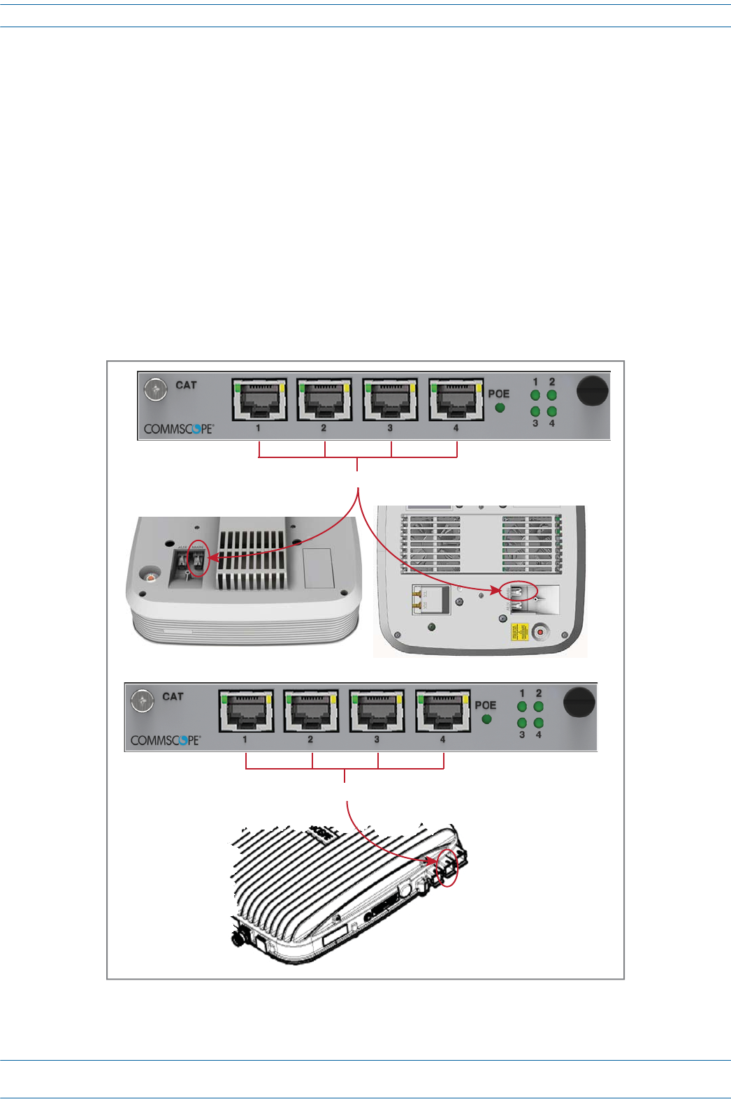
port).WhetherornottheUAPiscascadeddetermineshowyouconnecttheCATCardtoaUAP,as
describedbelow.
•Non-CascadedUAPS
Toconnectuptofourindividual,non-cascadedUAPstotheCATCardviaports1-4(oneperport).
–UAP,UAP-N25,andUAP-X:connecttheCATCardporttotheUAPMainport.
–CAPL:connecttheCATCardporttotheCAPLOpticalPort1.
AnEthernetdevicesuchasacameracanbeconnectedtotheAUXportofaUAPifAUTCardsare
installedintheTENorCAN.
UAP, UAP-N25 UAP-X
CAT Ports 1 - 4 to/from UAP Main port
CAT Ports 1 - 4 to/from CAP L Opcal Port 1
CAP L
M0201AA ION®-E Series Hardware Installation Guide
© June 2017 CommScope, Inc. Page 31
Installing Subracks and PSUs in an Equipment Rack
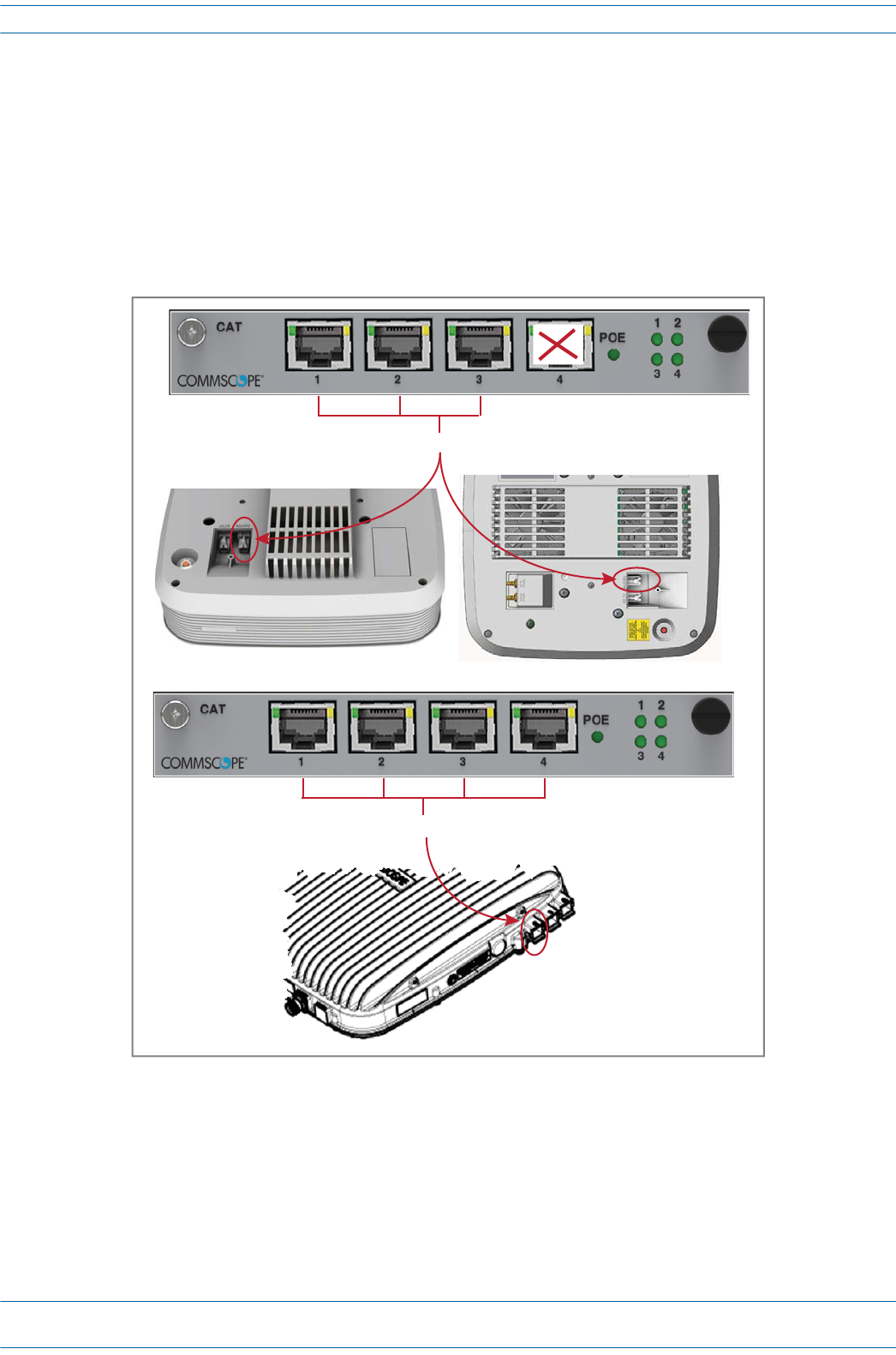
•CascadedUAPS
ToconnectuptothreecascadedpairsofUAPstotheCATCardviaports1-4(onepairperportwith
oneportunused).
–UAP,UAP-N25,andUAP-X:connecttheCATCardporttotheUAPMainport.
–CAPL:connecttheCATCardporttotheCAPLOpticalPort2.
CascadedUAPsdonotsupportEthernetdevices.Othercombinationsofcascadedandnon-cascaded
UAPsarealsopossibleaslongasthetotalnumberofUAPsconnectedtoaCATCarddoesnotexceed
six.
UAP, UAP-N25 UAP-X
CAT Ports 1 - 3 to/from UAP Main port
CAT Ports 1 - 3 to/from CAP L Opcal Port 2
CAP L

ION®-E Series Hardware Installation Guide M0201AA
Page 32 © June 2017 CommScope, Inc.
Installing Subracks and PSUs in an Equipment Rack
Connect the AUT Cards
ThefollowingrulesapplytotheAUTCardports1-8.
•TheoutsidenetworkthatsupportstheEthernetdeviceconnectedtotheUAPmustbeconnectedtothe
correspondingAUTCardandportofthesubrackcontainingtheCATcardtowhichtheUAPisconnected.
Ethernetbackhaulovertheopticallinkisnotsupported.
•BecausethepathfromtheUAPAUXporttoanAUTportpathisapass-throughconnection,noextra
networksetupproceduresfortheEthernetdevicearerequired.
•BecausetheUAP'sAUXportisconfiguredtosupportasecondUAPbydefault,therewillbeadelaybefore
theEthernetbackhaulpathattheAUTCardisreadytousewhenthedeviceisinitiallyconnected.When
anEthernetdeviceisconnectedtotheAUXportofaUAP,ION-Edetectsthedevice,re-flashestheUAPto
supportthedevice,andthenrebootstheUAP.TheUAPwillperformthere-flashandrebootprocess
whenevertheUAPorEthernetdeviceconnectedtotheAUXportischanged.TheUAP'sblueLEDwillblink
whilere-flashingwithoutinterruptingservice,buttheUAPwillexperienceashortserviceinterruptionof
approximately1.5minuteswhenitreboots.
•TheAUTpathisindependentofthesignalsetassignedtoaUAP,however,themaximumtransport
bandwidthfortheUAPisreducedfrom320MHzto280MHzwhenanEthernetdeviceisconnectedtothe
UAP.
•TheAUXportofacascaded(secondary)UAPcannotbeusedtoconnectanEthernetdevice.
•TheAUTCardportsdonotsupplypower,however,theUAPdoessupplyRemotePoweroverCat6Ato
connectedEthernetdevices.
•1Gbit/sand100Mbit/sEthernetdevicesaresupported.
M0201AA ION®-E Series Hardware Installation Guide
© June 2017 CommScope, Inc. Page 33
Installing Subracks and PSUs in an Equipment Rack
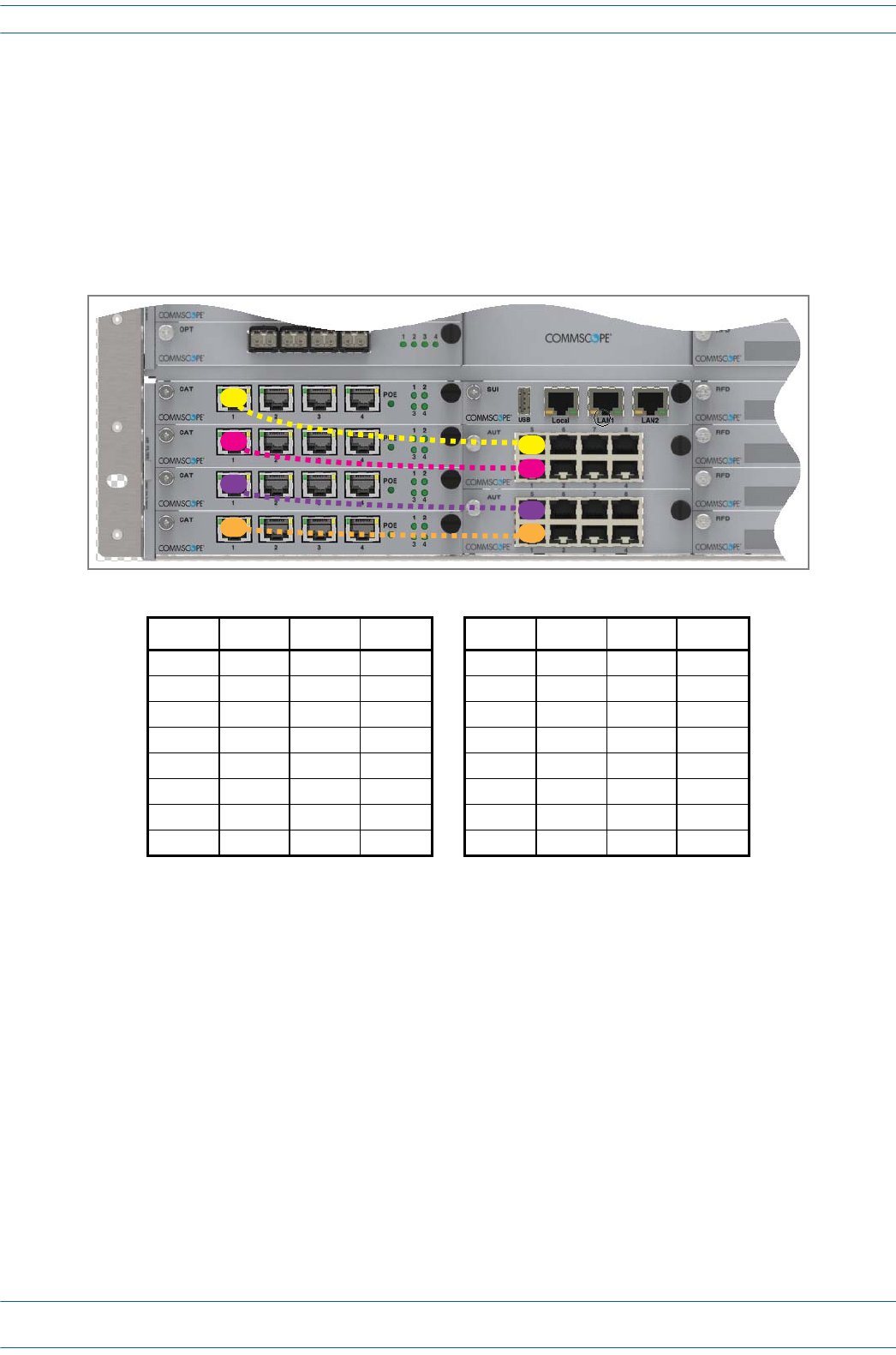
Figure3-3andTable3-1showtheinternalmappingbetweenCATCardsandAUTCards.Thereisaspecific
relationshipbetweentheslotinwhichtheCATandAUTCardsareinstalled,andtheCATCardandAUTCard
ports.Forexample:
•TheCATCardslot/portcombinationofL1.1alwaysmapstoAUTCardslot/portcombinationM1.1
•TheCATCardslot/portcombinationL4.4alwaysmapstoAUTCardslot/portcombinationM2.8.
ThisinternalmappingprovidestheEthernetbackhaulforEthernetdevicesconnectedtotheEthernetports
ontheAUTCard.
Figure 3-3. Example of Internal Mapping of CAT Card Ports to AUT Ports
UsetheprecedinginformationandthefollowingstepstoconnecttheAUTCard(s)totheION-Esystem.
1Followthestepsin"InstalltheCANandTENCards”onpage27toinstalltheAUTCard(s)intotheWCS
SubrackSlotsM1-M2,asneededforthisCAT/TENinstallation.
2RefertoFigure3-3andTable3-1toconnectEthernetcablesfromtheEthernetdevicestotheAUTCard's
RJ45ports.
Table 3-1. Internal Mapping of CAT Card Slots/Ports to AUT Card Slots/Ports
WCS Slot CAT Port AUT Slot AUT Port WCS Slot CAT Port AUT Slot AUT Port
L1 1M1 1L3 1M2 1
L1 2M1 2L3 2M2 2
L1 3M1 3L3 3M2 3
L1 4M1 4L3 4M2 4
L2 1M1 5L4 1M2 5
L2 2M1 6L4 2M2 6
L2 3M1 7L4 3M2 7
L2 4M1 8L4 4M2 8

ION®-E Series Hardware Installation Guide M0201AA
Page 34 © June 2017 CommScope, Inc.
Installing Subracks and PSUs in an Equipment Rack

M0201AA ION®-E Series Hardware Installation Guide
© June 2017 CommScope, Inc. Page 35
Chapter Topics Page
Point Of Interface (e-POI) Subrack ...................................................................................................................................................................... 36
e-POI Subrack Back Panel Connectors............................................................................................................................................................ 36
Interface Card (IFC)......................................................................................................................................................................................... 37
e-POI Module.................................................................................................................................................................................................. 38
Installing an e-POI Subracks and Modules .......................................................................................................................................................... 39
Removing an e-POI Module from an e-POI Subrack............................................................................................................................................ 40
e-POI Subrack and Component Specifications ....................................................................................................................................................41
ThischapterprovidesaproductoverviewandinstallationinstructionsfortheION-ESeriesPointofInterface
(e-POI)Subracks.
UNRESOLVED: The current e-POI instruction sheet has 7/16 DIN connectors. We need to update the
instructions to the now0used 4.3-10 connectors. Request for information out to Dieter
Schiele, who is out of the office until 3July17.
UNRESOLVED: Also, not sure why the e-POI was not included in the ION-E Series Software Version 2.0.0
User’s Manual (PN M0201A0D), but I am adding it to this new ION-E HW install guide.
POINT OF INTERFACE (E-POI) SUBRACKS 4
ION®-E Series Hardware Installation Guide M0201AA
Page 36 © June 2017 CommScope, Inc.
Point Of Interface (e-POI) Subrack
POINT OF INTERFACE (E-POI) SUBRACK
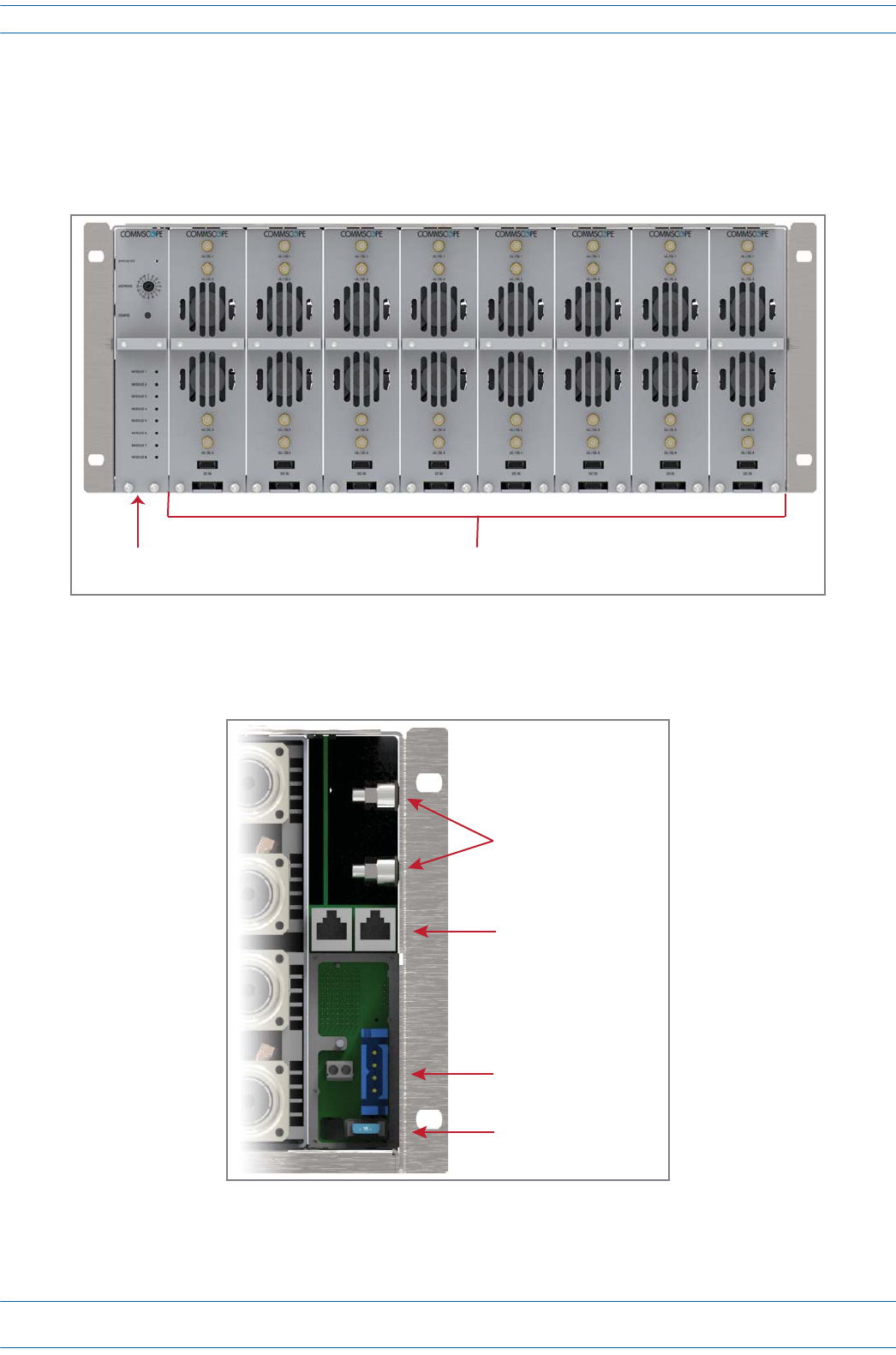
TheuniversalION-EPointOfInterface(e-POI)Subrackprovidespower,housing,andcommunicationsforup
toeighte-POIRFDonor(RFD)Cards.[what does the “e” in e-POI mean?]
e-POI Subrack Back Panel Connectors
Interface Car
(IFC)
e-Poi Subrack supports up to 8 RFD Cards
Ground studs
Communicaon ports
(to WCS Subrack)
12 Vdc Input connector
(from WCS Subrack)
15A Blade Fuse
M0201AA ION®-E Series Hardware Installation Guide
© June 2017 CommScope, Inc. Page 37
Point Of Interface (e-POI) Subrack
Interface Card (IFC)
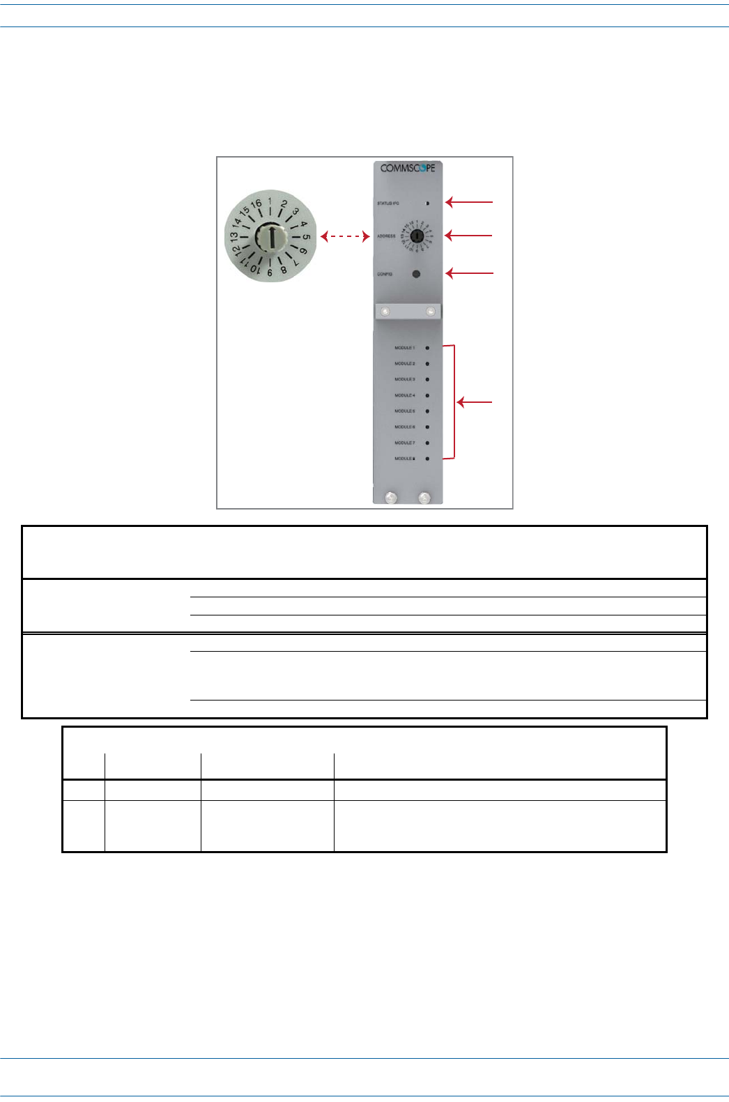
TheInterfaceCard(IFC)providescommunications,status,andalarmsforthee-POIModulesinstalledinthe
e-POISubrack.
UNRESOLVED: Not sure about IFC Status LED. In original e-POI instructions, graphic labeled it the “IFC
module status,” but the definition referred to “e-POI” so is this Status for the IFC or the full
e-POI Subrack?
UNRESOLVED: For e-POI Module Status LEDS” Red state, original doc said was “IFC temperature alarm,”
which does not make sense, as there are 8 LEDs. However, please verify that my correction
above is correct.
IFC LEDs
Ref # LED LED Color Description
1 Status • Off • IFC not fully seated in slot or not receiving power.
• Green • IFC functioning to specification.
•Red •Active alarm on IFC.
4 e-POI Module
Status 1 - 8
• Off • e-POI Module in corresponding slot is not receiving power.
• Green • e-POI Module in corresponding slot is functioning to specification. RFD Card
Status LED must be green before connecting corresponding RF signals to
input.
•Red •e-POI Module in corresponding slot has active temperature alarm.
IFC Connectors
Ref # Component Device Function
2 Address switch Rotary dial Must be set to 1.
3 Config button Pushbutton Alerts ION-E Software to scan for and remove references to
removed RFD Cards; see "Removing an e-POI Module from an
e-POI Subrack” on page 40.
1
2
3
4
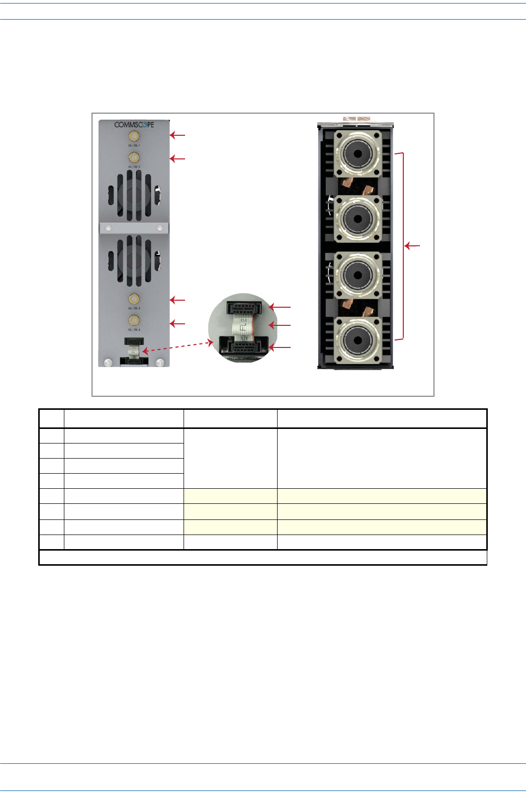
ION®-E Series Hardware Installation Guide M0201AA
Page 38 © June 2017 CommScope, Inc.
Point Of Interface (e-POI) Subrack
e-POI Module
Thee-POIModulesprovideawide-band,highpower,low-PIM,interfaceandattenuationfortheION-ERFD
Cards.
Ref # Component Device Function
1UL/DP Port 1
Female QMA connector Connect to the RFD Card Ports 1 - 4.
2UL/DP Port 2
3UL/DP Port 3
4UL/DP Port 4
5Module Power/Com port
6Ribbon cable 1
7e-Poi Subrack Power/Com port
8UL/DL Ports 7/16 DIN connectors Connect to the eNodeB.
1 The Ribbon cable is connected after the e-POI Module is installed in the e-POI Subrack.
8
e-Poi Module
Back Panel
e-Poi Module
Front Panel
1
2
3
4
5
6
7

M0201AA ION®-E Series Hardware Installation Guide
© June 2017 CommScope, Inc. Page 39
Installing an e-POI Subracks and Modules
INSTALLING AN E-POI SUBRACKS AND MODULES
UNRESOLVED: I could not find any installation steps. Emulate what was provided for WCS subracks?
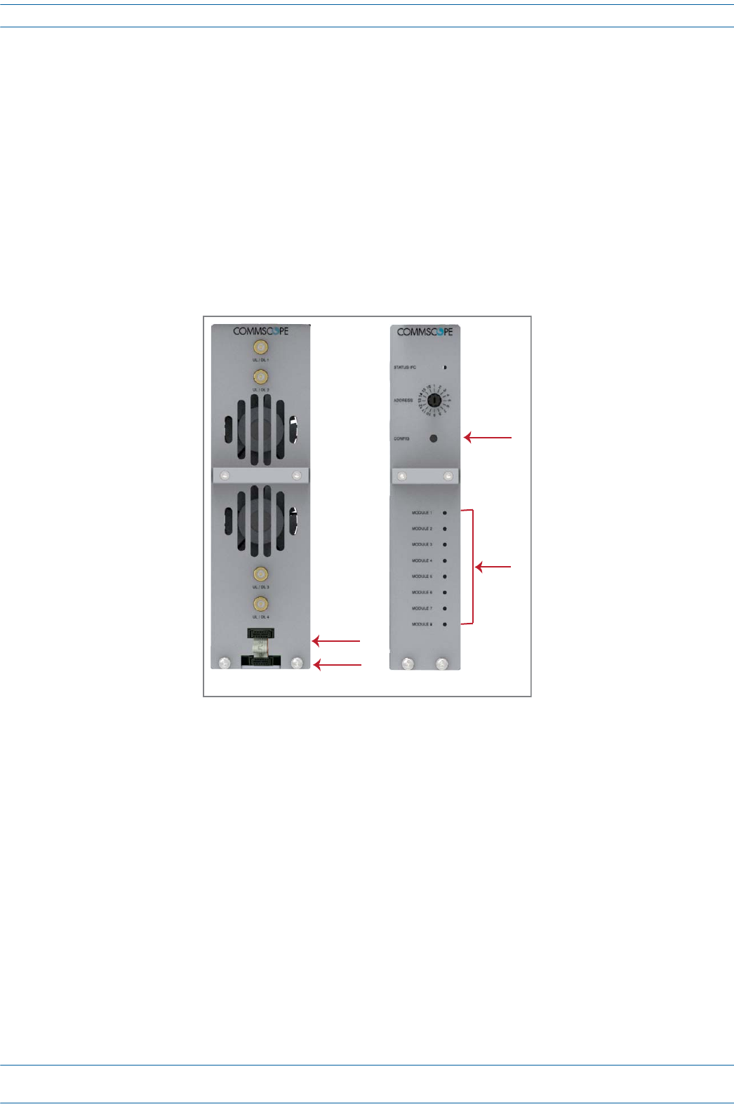
ION®-E Series Hardware Installation Guide M0201AA
Page 40 © June 2017 CommScope, Inc.
Removing an e-POI Module from an e-POI Subrack
REMOVING AN E-POI MODULE FROM AN E-POI SUBRACK
TheION-ESoftwareautomaticallydetectswhenane-POIModuleisaddedtoane-POISubrack.Ifyouneedto
removeane-POIModule,youmustdothefollowing:
1DisconnecttheRibboncablefromthee-POIModulethatyouareremovingfromthee-POISubrack.
2Loosenthetwothumbscrewsonthebottomofthee-POIModuleandpullitfromthesubrack.
3PresstheConfigbuttonontheIFCfor5seconds.ThistellstheION-ESoftwaretoscananddeletethe
removede-POIModulefrominventoryandclearanyalarmsrelatedtothate-POIModule.
4Waitforthee-POIModuleStatusLEDSontheIFCtoflashoffandthenon,whichindicatesthattheIFChas
beenreconfigured.
e-Poi Module
1
2
3
4
IFC
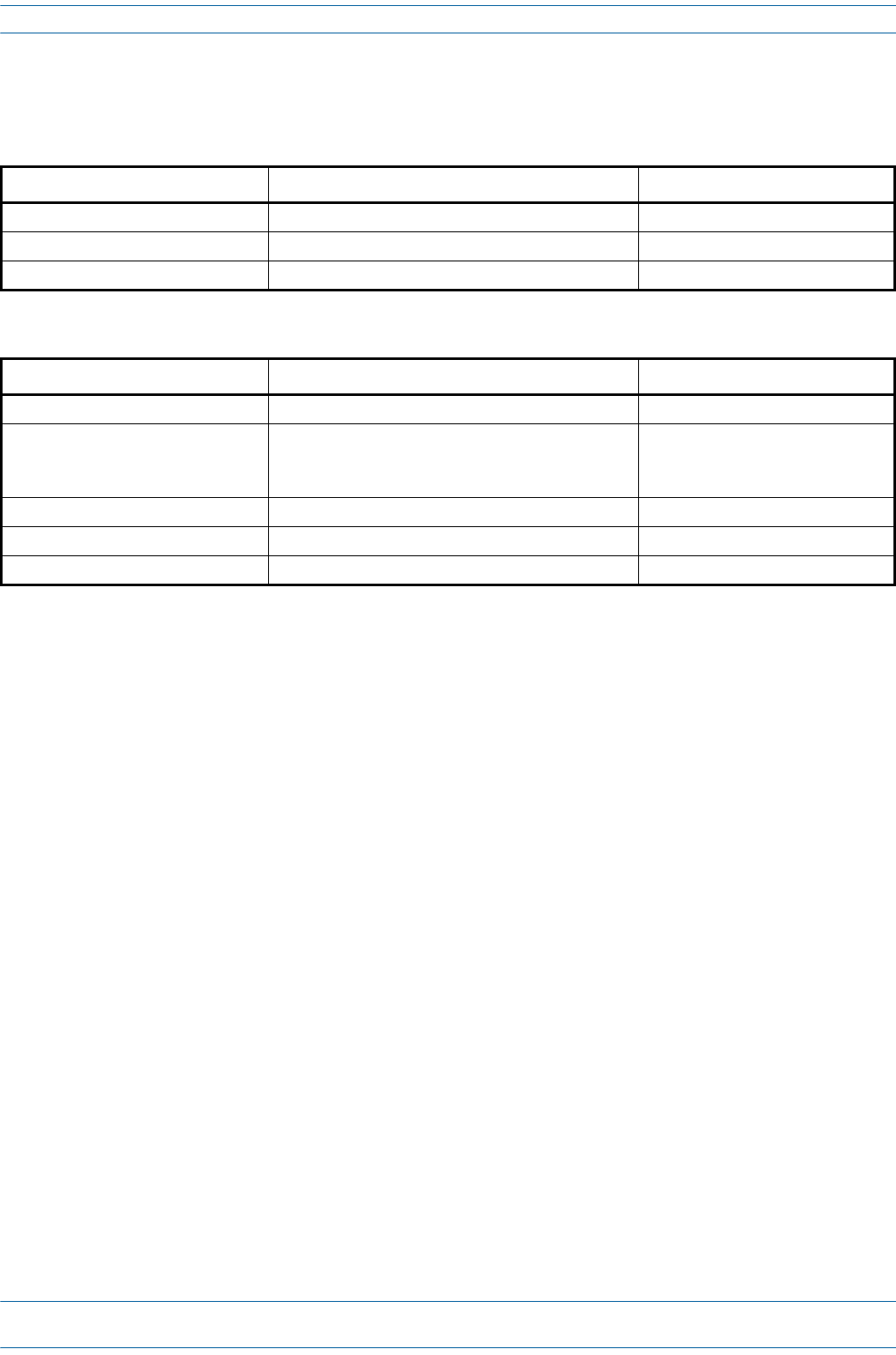
M0201AA ION®-E Series Hardware Installation Guide
© June 2017 CommScope, Inc. Page 41
e-POI Subrack and Component Specifications
E-POI SUBRACK AND COMPONENT SPECIFICATIONS
Table 4-1. e-POI Subrack Specifications
Parameter Specification Notes
Height x width x depth, mm 4U x 19" x 395
Weight, kg* 7.7
Operating temperature, °C -5 to +50 Support rails are required for rack mounting
Table 4-2. e-POI Module Specifications
Parameter Specification Notes
Operational frequency, MHz 300 to 2700
Attenuation, dB • 30 ±2 698-2700 MHz
• 35.5 ±3.5 380-450 MHz
• 33.5 ±3.2 450-698 MHz
RF input power +46 dBm
PIM @ 2x20 Watts (3rd order) -153 dBc
Input voltage, Vdc / Power consumption 12/10 Watts

ION®-E Series Hardware Installation Guide M0201AA
Page 42 © June 2017 CommScope, Inc.
e-POI Subrack and Component Specifications

M0201AA ION®-E Series Hardware Installation Guide
© June 2017 CommScope, Inc. Page 43
Chapter Topics Page
Power Supply Unit (PSU) ..................................................................................................................................................................................... 44
PSU Modules and Connectors ........................................................................................................................................................................ 44
12 Vdc Power Module LEDs............................................................................................................................................................................ 45
57 Vdc Power Module LEDs............................................................................................................................................................................ 46
Installing PSUs ..................................................................................................................................................................................................... 47
ThischapterprovidesaproductoverviewandinstallationinstructionsfortheION-ESeriesPowerSupply
Unit(PSU).
POWER SUPPLY UNIT (PSU) 5
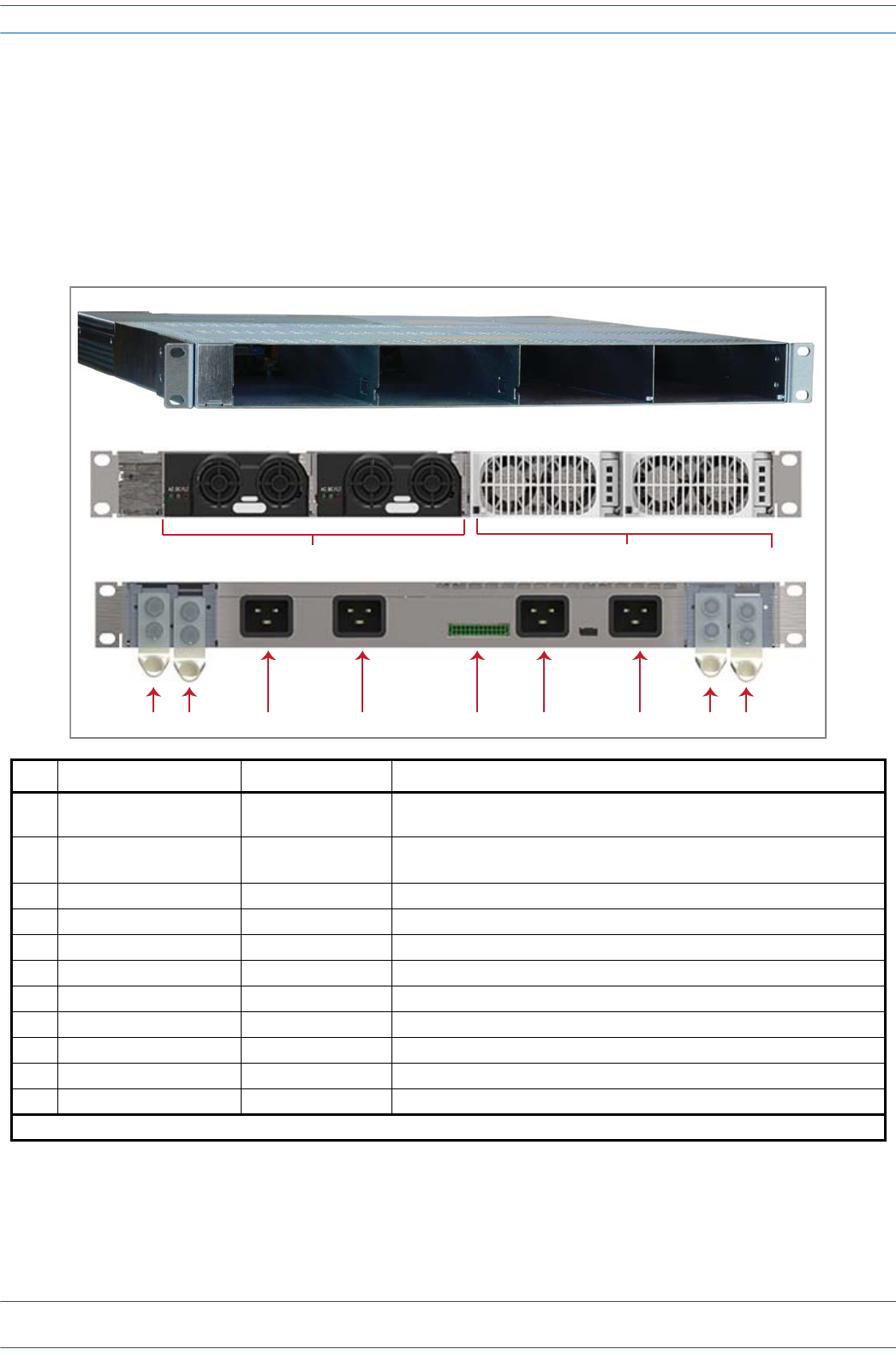
ION®-E Series Hardware Installation Guide M0201AA
Page 44 © June 2017 CommScope, Inc.
Power Supply Unit (PSU)
POWER SUPPLY UNIT (PSU)
ThePowerSupplyUnit(PSU)isasubrackthathousestwo12VdcPowerModulesandtwo57VdcPower
Modules,whichprovidepowertotheWCSsubracks,UAPs,andconnecteddevices.
PSU Modules and Connectors
Ref # Component Device Function
112 Vdc Power Module Power module Plugs into the Power Supply Subrack to provide 12 Vdc power to the WCS and
e-POI subracks.
257 Vdc Power Module Power module Plugs into the Power Supply Subrack to provide remote power over Cat6A for
the UAP and devices connected to the UAP.1
3+57 Vdc Output Power terminal Provides the connection point for the Positive (Red Wire).
4-57 Vdc Output Power terminal Provides the connection point for the RTN Negative (Black Wire).
5AC Input (IEC 60320 C19) Power connector Provides the connection point for the for 57V module Slot 4.
6AC Input (IEC 60320 C19) Power connector Provides the connection point for the for 57V module Slot 3.
7Rectifier control connector 24 pin-terminal block Provides the connection point for the to the WCS.
8AC Input (IEC 60320 C19) Power connector Provides the connection point for the for 12V module Slot 2.
9AC Input (IEC 60320 C19) Power connector Provides the connection point for the for 12V module Slot 1.
10 +12 Vdc Output Power terminal Provides the connection point for the Positive (Red Wire).
11 -12 Vdc Output Power terminal Provides the connection point for the RTN Negative (Black Wire).
1 Unless otherwise noted, the use of “UAP” collectively refers to the UAP, UAP-X, UAP-N25, and the CAP L.
Front Panel
12
Rear Panel
34 5 678 10911
Power Supply Subrack - Unpopulated
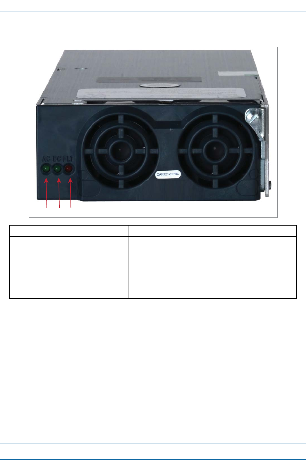
M0201AA ION®-E Series Hardware Installation Guide
© June 2017 CommScope, Inc. Page 45
Power Supply Unit (PSU)
12 Vdc Power Module LEDs
Ref # LED LED Color Description
1 AC Green AC input is within the specified range.
2 DC Green DC output is within the specified range.
3 FLT (Fault) Red There is no AC input or a failure has been detected in the 12 Vdc Power
Module. The Fault LED activates under the following conditions:
• If two 12 Vdc Power Modules are installed in the PSU, and the AC input is
removed (cable unplugged) from one of the modules.
• If only one 12 Vdc Power Module is installed in the PSU, and AC power is
removed.
123
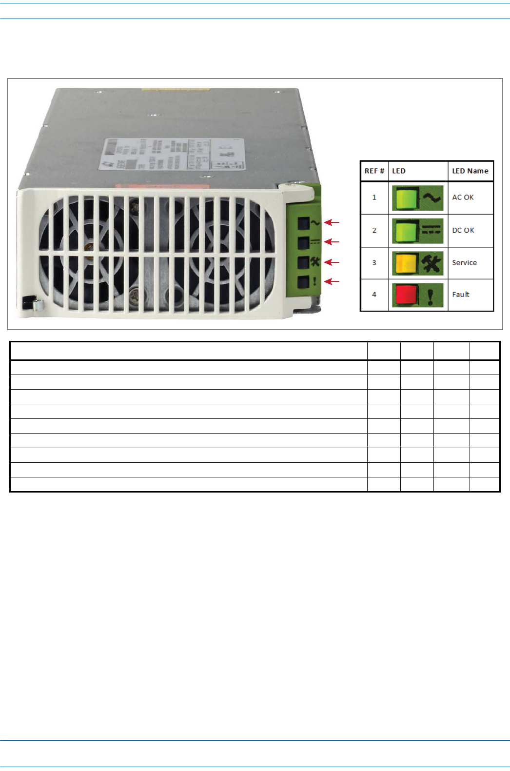
ION®-E Series Hardware Installation Guide M0201AA
Page 46 © June 2017 CommScope, Inc.
Power Supply Unit (PSU)
57 Vdc Power Module LEDs
Condition AC OK DC OK Service Fault
Unit is functioning to specification On On Off Off
Thermal shutdown On On On Off
Defective fan, blown AC fuse in Power Module, boost stage failure, over voltage latched shutdown On Off Off On
No AC <15 mS (single unit) Off On Off Off
AC present but not within limits Blinks Off Off Off
AC not present Off Off Off Off
Over current On Blinks Off Off
Non-catastrophic internal failure (any detectable fault that does not shut down the unit) On On Off On
Communications fault (RS485 mode) On On Off Blinks
1
2
3
4

M0201AA ION®-E Series Hardware Installation Guide
© June 2017 CommScope, Inc. Page 47
Installing PSUs
INSTALLING PSUS
UNRESOLVED: I could not find any installation steps.
UNRESOLVED: Do we have any power consumption specs?

ION®-E Series Hardware Installation Guide M0201AA
Page 48 © June 2017 CommScope, Inc.
Installing PSUs

M0201AA ION®-E Series Hardware Installation Guide
© June 2017 CommScope, Inc. Page 49
Chapter Topics Page
Identifying UAPs in the ION-E Software ......................................................................................................................................................... 50
UAPs and UAP-N25s ....................................................................................................................................................................................... 51
UAP-X.............................................................................................................................................................................................................. 52
Installing UAPs..................................................................................................................................................................................................... 53
Using the UAP Ceiling Mount Assembly (PN 7683182-00) ............................................................................................................................. 53
Required Tools for a Standard UAP Ceiling Mount .................................................................................................................................. 53
Unpack and Inspect the Ceiling Mount Assembly.................................................................................................................................... 53
Standard Ceiling Mount Overview ........................................................................................................................................................... 54
Standard Ceiling Mount Installation Steps............................................................................................................................................... 55
Mounting a UAP Using a UAP Quick Release Ceiling Mount Kit..................................................................................................................... 57
Required Tools for a Quick Release Ceiling Mount Kit............................................................................................................................. 57
Unpack and Inspect the Quick Release Ceiling Mount Kit ....................................................................................................................... 58
Overview of Using a Quick Release Ceiling Mount Kit ............................................................................................................................. 58
Mount the UAP to the Ceiling ..................................................................................................................................................................59
Connect the UAP Cables........................................................................................................................................................................... 61
Install the UAP.......................................................................................................................................................................................... 62
Mounting a UAP to a Wall Using the UAP Wall Mounting Kit (PN 7683181-00) ............................................................................................ 63
Required Tools for a Wall Mount............................................................................................................................................................. 63
Unpack and Inspect the Wall Mounting Kit.............................................................................................................................................. 64
Mount the UAP to a Wall ......................................................................................................................................................................... 64
UAP, UAP-N25, and UAP-X Cable Requirements............................................................................................................................................ 67
Cascading a UAP, UAP-X, or UAP-N25 ............................................................................................................................................................68
UAP Maintenance................................................................................................................................................................................................ 69
Remove a UAP from a Ceiling Mount .............................................................................................................................................................69
Remove a UAP from a Wall Mount................................................................................................................................................................. 70
Preventative UAP Maintenance ..................................................................................................................................................................... 71
UAP Specifications............................................................................................................................................................................................... 72
UAP Output Specifications.............................................................................................................................................................................. 72
UAP Bandwidth Specifications........................................................................................................................................................................ 73
ThischapterprovidesaproductoverviewandinstallationinstructionsfortheION-ESeriesUniversalAccess
Points(UAPs)thatcanbedeployedinanION-Esystem.UAPsallowtransmissionbetweentheION-E
equipmentandantennasandEthernetdevices(suchasWiFiandIPcameras).
•"UAPsandUAP-N25s”onpage51
•"UAP-X”onpage52.
UNIVERSAL ACCESS POINTS 6
This installation guide uses “UAP” to collectively refer to the UAP, UAP-X, and UAP-N25. Differences will
be identified by specific UAP product name.
For information on the Carrier Access Point, Low Power (CAP L), go to "Carrier Access Point, Low Power
(CAP L)” on page 75.
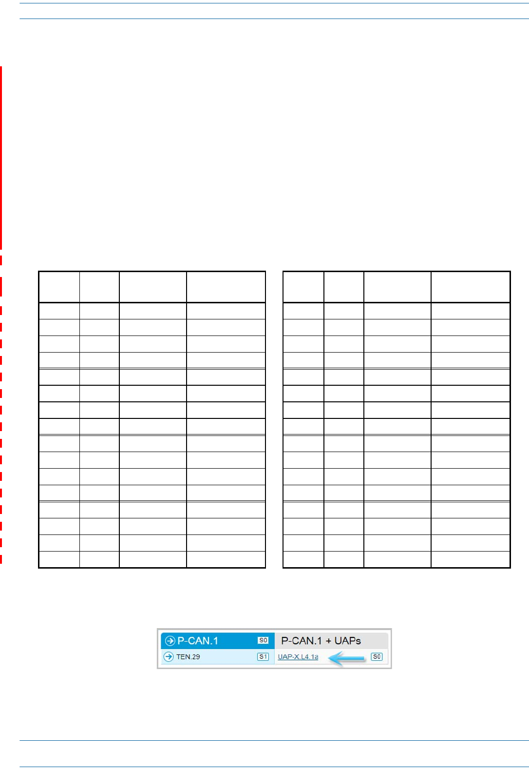
ION®-E Series Hardware Installation Guide M0201AA
Page 50 © June 2017 CommScope, Inc.
Identifying UAPs in the ION-E Software
UAPnumberingisbasedontheCATcardsslotandportnumbersintheassociatedCANorTENandwhether
theUAPisdirectlyconnectedtotheCATcard(a)orconnectedtotheAUXportofanotherUAP(b).
TheION-EGUIlabelsUAPsasfollows:
<DisplayName>.<Slot ID>.<Port#><a or b>
Where
•<DisplayName>istheUAPname,suchasUAPorUAP-X
•<Slot ID>istheWCS-2orWCS-4Subrackslot(L1toL8),shownasaalpha-numericalintegerfromL1-L8
•<Port #>istheCATCardPortnumber(1-4),shownasanumericalintegerfrom1-4
•<a or b>iswhethertheUAPisthemain/primaryUAP(a)orthecascaded/secondaryUAP(b).
UAPswithexternalantennaconnectorsareidentifiedasUAP-XontheSignal Distributionpageasshownin
Figure6-1.
Figure 6-1. Identifying UAP-X Units in the ION-E Software
Table 6-1. UAP Identification in the ION-E Software
WCS Slot CAT Port Primary UAP
(Direct Connect)
Secondary UAP
(AUX Port Connect)
WCS Slot CAT Port Primary UAP
(Direct Connect)
Secondary UAP
(AUX Port Connect)
L1 1UAP.L1.1a UAP.L1.1b L5 1UAP.L5.1a UAP.L5.1b
L1 2UAP.L1.2a UAP.L1.2b L5 2UAP.L5.2a UAP.L5.2b
L1 3UAP.L1.3a UAP.L1.3b L5 3UAP.L5.3a UAP.L5.3b
L1 4UAP.L1.4a UAP.L1.4b L5 4UAP.L5.4a UAP.L5.4b
L2 1UAP.L2.1a UAP.L2.1b L6 1UAP.L6.1a UAP.L6.1b
L2 2UAP.L2.2a UAP.L2.2b L6 2UAP.L6.2a UAP.L6.2b
L2 3UAP.L2.3a UAP.L2.3b L6 3UAP.L6.3a UAP.L6.3b
L2 4UAP.L2.4a UAP.L2.4b L6 4UAP.L6.4a UAP.L6.4b
L3 1UAP.L3.1a UAP.L3.1b L7 1UAP.L7.1a UAP.L7.1b
L3 2UAP.L3.2a UAP.L3.2b L7 2UAP.L7.2a UAP.L7.2b
L3 3UAP.L3.2a UAP.L3.2b L7 3UAP.L7.2a UAP.L7.2b
L3 4UAP.L3.4a UAP.L3.4b L7 4UAP.L7.4a UAP.L7.4b
L4 1UAP.L4.1a UAP.L4.1b L8 1UAP.L8.1a UAP.L8.1b
L4 2UAP.L4.2a UAP.L4.2b L8 2UAP.L8.2a UAP.L8.2b
L4 3UAP.L4.3a UAP.L4.3b L8 3UAP.L8.3a UAP.L8.3b
L4 4UAP.L4.4a UAP.L4.4b L8 4UAP.L8.4a UAP.L8.4b
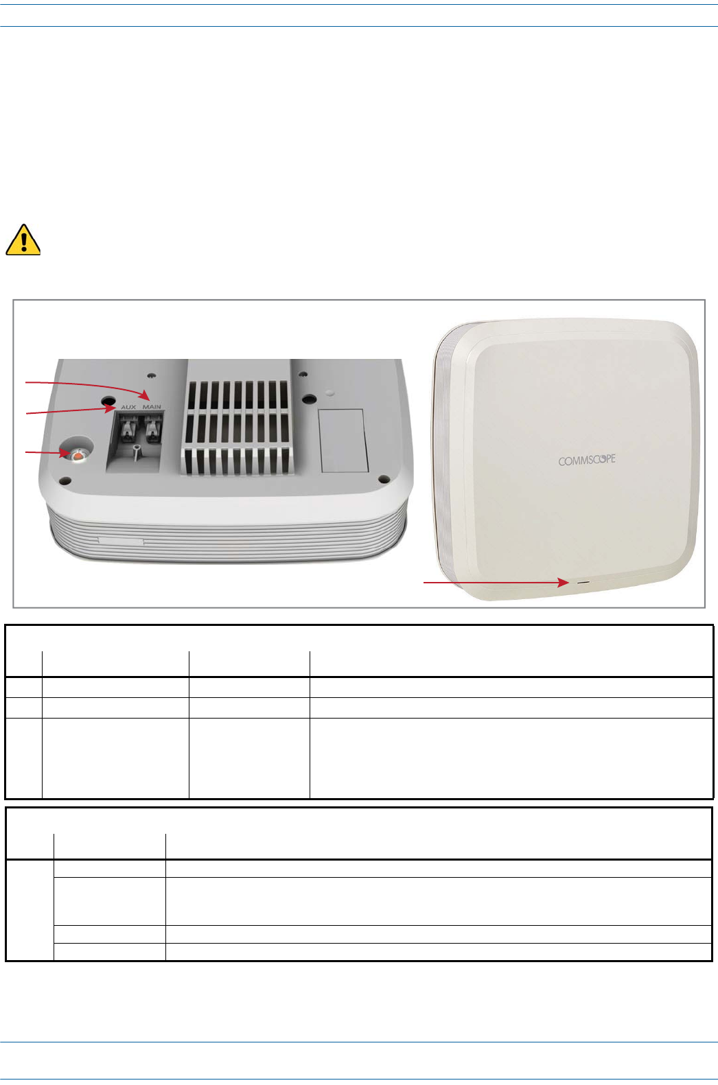
M0201AA ION®-E Series Hardware Installation Guide
© June 2017 CommScope, Inc. Page 51
UAPs and UAP-N25s
TheUAPandUAP-N25transmitandreceivesignalsviaCat6AcablingbetweentheCAN/TENandanindoor
antenna.TheUAPalsosupportsEthernetbackhauloranadditionalUAPthroughasecondRJ45jack.
TheUAP-N25issimilartotheUAP.UAPssupport380to2700MHzinfour75-MHzblocks.TheN25hasafilter
thatrestrictsthesecondreceiverto25MHz.ThisallowsION-Etosupportcertainbandcombinationsin
whichanarrowreceivebandexistsbetweentwotransmitbands.
The UAP and UAP-N25 are designed for indoor use only.
UAP Connectors
Ref # Component Device Function
1Main port RJ45 connector Provides data and power to UAP over Cat6A.
2AUX port RJ45 connector Provides data and power to 2nd UAP or Ethernet devices.
3Power button Pushbutton switch Turns power to UAP on/off. Power to the UAP may also be shutdown via the
ION-E Series Software.
CAUTION! Prior to disconnecting a Cat6A cable from the UAP, press the
red Power button to power off the UAP.
UAP Status LED (unlabeled)
Ref # LED Color Description
4• Blue • UAP is transmitting as expected.
• Fast-flash blue • Unit Identifier activated in the ION-E GUI; for information on how to flash identify a UAP, see “Flash UAP
Led” section of the ION-E Series software configuration guide that corresponds to the ION-E Software
Release installed on this ION-E system.
• Slow-flash blue • UAP firmware update is in process.
• Yellow • Active alarm; see Active Alarms page in GUI.
Front of UAP
4
Boom of UAP (paral view)
1
2
3
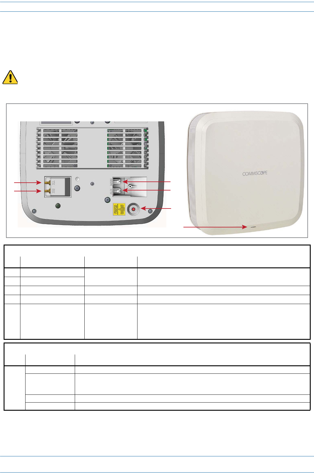
ION®-E Series Hardware Installation Guide M0201AA
Page 52 © June 2017 CommScope, Inc.
UAP-X
TheUAP-XisfunctionallyidenticaltotheUAP,butisdesignedtoworkwithexternalantennasratherthanthe
internalantennasusedinthestandardUAP.
The UAP-X is intended for indoor use only.
UAP-X Connectors
Ref # Component Device Function
1TX port Female QMA
connector Connects the UAP-X yo external antenna.
2RX port
3Main port RJ45 connector Provides data and power to UAP over Cat6A.
4 AUX port RJ45 connector Provides data and power to 2nd UAP or Ethernet devices.
5Power button Pushbutton switch Turns power to UAP on/off. Power to the UAP may also be shutdown via the
ION-E Series Software.
CAUTION! Prior to disconnecting a Cat6A cable from the UAP-X, press
the red Power button to power off the UAP-X.
UAP-X Status LED (unlabeled)
Ref # LED Color Description
6• Blue • UAP is transmitting as expected.
• Fast-flash blue • Unit Identifier activated in the ION-E GUI; for information on how to flash identify a UAP, see “Flash UAP
Led” section of the ION-E Series software configuration guide that corresponds to the ION-E Software
Release installed on the this ION-E system.
• Slow-flash blue • UAP firmware update is in process.
• Yellow • Active alarm; see Active Alarms page in GUI.
Front of UAP-X
6
Boom of UAP-X (paral view)
13
2
4
5
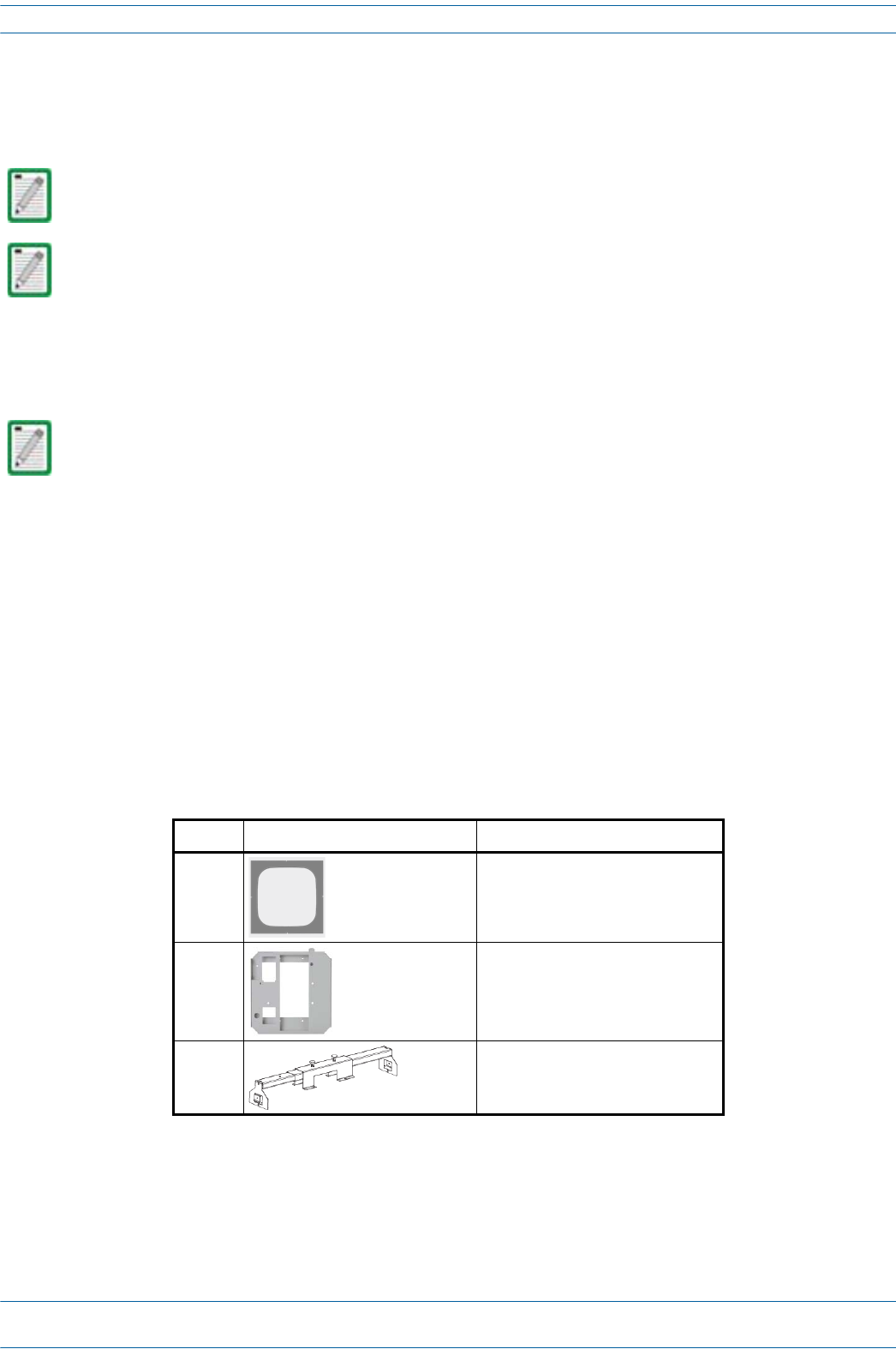
M0201AA ION®-E Series Hardware Installation Guide
© June 2017 CommScope, Inc. Page 53
Installing UAPs
INSTALLING UAPS
ThefollowingsectionsdescribethestepsrequiredtoinstallaUAP.
Using the UAP Ceiling Mount Assembly (PN 7683182-00)
Required Tools for a Standard UAP Ceiling Mount
•#2Phillips-Headscrewdriver
•Cuttingtooltocutopenceilingtile
Unpack and Inspect the Ceiling Mount Assembly
1Inspecttheexterioroftheshippingcontainer(s)forevidenceofroughhandlingthatmayhavedamaged
thecomponentsinthecontainer.
2Unpackeachcontainerwhilecarefullycheckingthecontentsfordamageandverifywiththepackingslip.
3Ifdamageisfoundorpartsaremissing,fileaclaimwiththecommercialcarrierandnotifyCommScope
TechnicalSupport(see"ContactingDCCSGlobalTechnicalSupport”onpage126).Savethedamaged
cartonsforinspectionbythecarrier.
4Saveallshippingcontainersforuseiftheequipmentrequiresshipmentatafuturedate.
Unless otherwise noted, the use of “UAP” in the Universal Access Point installation procedures collectively
refers to the UAP, UAP-N25, and the UAP-X.
For information on how to install a CAP L, go to "Installing CAP Ls” on page 89.
For information on mounting a UAP to a ceiling using the UAP Quick Release Ceiling Mount Kit, go to
"Mounting a UAP Using a UAP Quick Release Ceiling Mount Kit” on page 57.
Table 6-2. Components of the UAP Wall Mounting Kit (PN 7683182-00)
Quantity Component Description
1Template
1 UAP Shroud
2Two-Part Sliding Support Bars
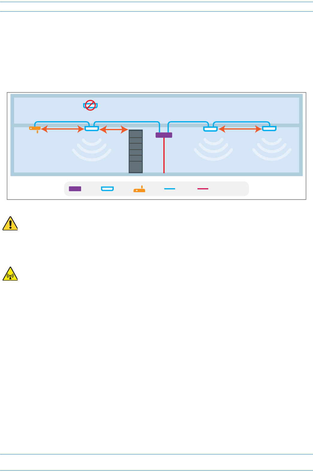
ION®-E Series Hardware Installation Guide M0201AA
Page 54 © June 2017 CommScope, Inc.
Installing UAPs
Standard Ceiling Mount Overview
TheUAPisequippedwithagroundingstudlocatedinthecenteroftheunit,however,groundingisnot
requiredasUAPsareclassifiedaslow-voltagedevicesanddonothaveinternalpowersupplies.CommScope
recommendscheckingyourlocalandnationalelectricalcodestodetermineifgroundingisarequirement.
FollowtheguidelinesshowninthefollowingdiagramwheninstallingUAPsintheceiling.Ceilingmountkits
andwallmountkitsareavailable.
The UAP-X does not meet the UL2043 requirements for installation of powered equipment (without a fire
enclosure) in air handling spaces. Installation of the UAP-X below the ceiling is recommended. If
installation of the UAP-X above the ceiling is desired, it is the installer's responsibility to confirm that the
installation complies with all local and national electrical, safety, and fire codes. In addition, if the UAP-X
is mounted above the ceiling, the installer must ensure that sufficient space is maintained around the
UAP-X for adequate cooling.
Care must be taken when positioning the antennas connected to the UAP-X to ensure sufficient isolation
between the TX and RX antennas. If frequencies below 512 MHz are used, the Ethernet signals in the Cat6A
cables may cause RX interference. If signals below 512 MHz are used, then the RX antenna should be
placed more than 6 meters from the UAP-X or more than 2 meters from the units if steps are taken to
mitigate interference from the Cat6A cables. Please see the UAP-X Antenna Installation Guidelines
document for more details.
TEN WiFi
UAP MM/SM FiberCat6A
WiFi
3m min
3m min
Install below ceiling grid only
2m min
Collocated UAPs (MIMO)
Metal Cabinet
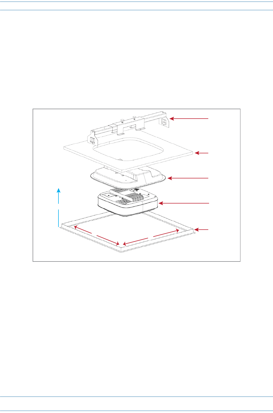
M0201AA ION®-E Series Hardware Installation Guide
© June 2017 CommScope, Inc. Page 55
Installing UAPs
Standard Ceiling Mount Installation Steps
1Usingthesuppliedtemplateasaguide,cutanopeninginthecenterofaceilingtilefortheUAP.
2PlacetheUAPonaflatsurfacesuchasatablewiththetopoftheunitfacedown(connectorsup).
3PlacetheshroudoverthetopoftheUAPsothatthescrewholesandcablecutoutsalignproperly.
4Placetheceilingtileovertheshroudwiththefinishedsurfaceoftheceilingtilefacingdownward.
5Placethetwo-partslidingsupportbarontopoftheshroudandalignitwiththecenteroftheUAP.
6Placemountingbracketovertheslidingsupportbarandalignitwiththethreadedmountingholesinthe
UAP.
Sliding
Mounng
Bracket
Ceiling le
UAP Shroud
UAP
Ceiling grid
Y
X
60 cm min.
(23.6 in min.)
60 cm min. - 76 cm max.
(23.6 in min. - 29.9 in max.)
Recommended
overhead clearance
is 70 cm (27.6 in)
Z
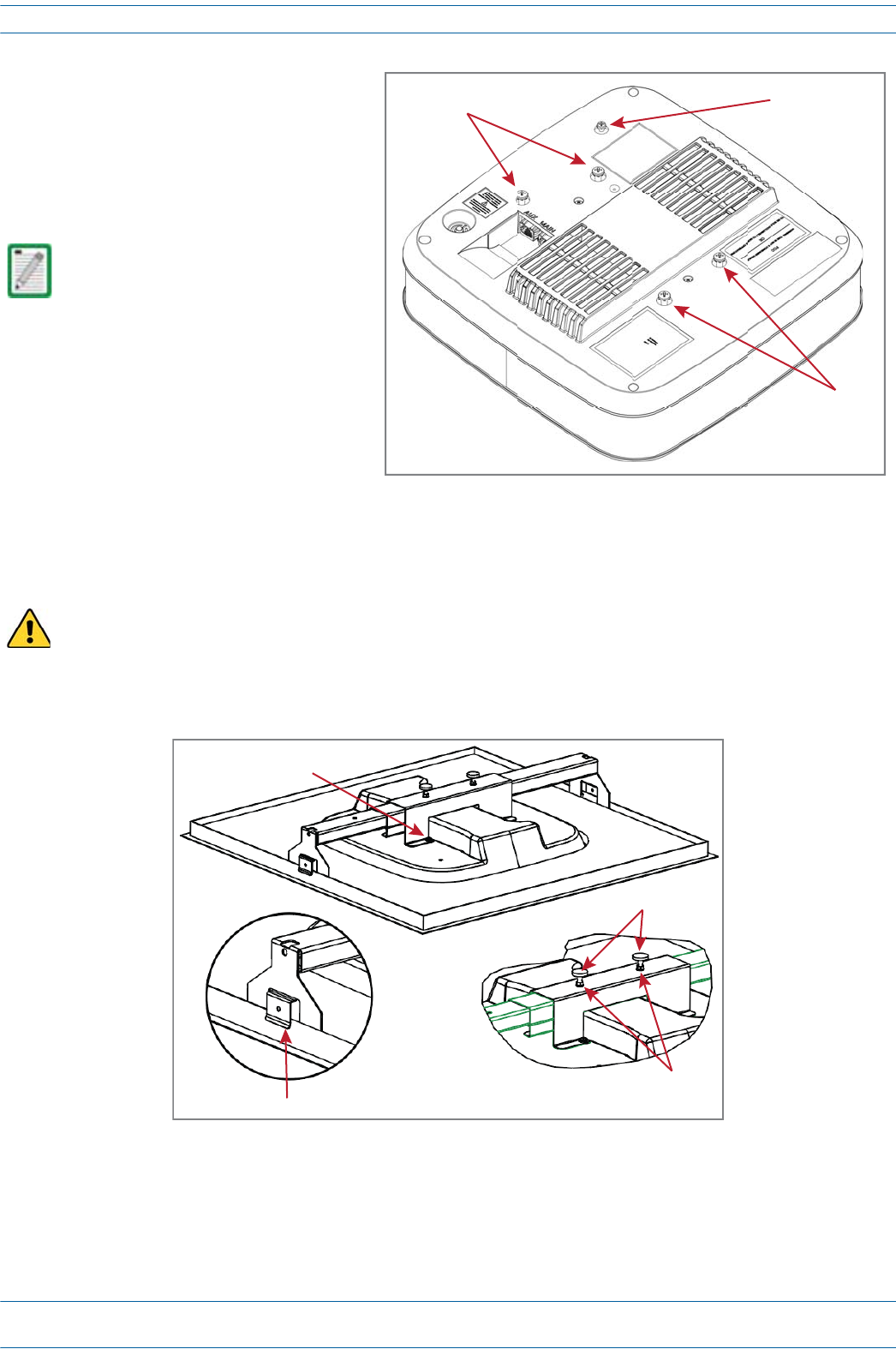
ION®-E Series Hardware Installation Guide M0201AA
Page 56 © June 2017 CommScope, Inc.
Installing UAPs
7InsertandtightenthefourM5X10
machinescrewstosecurethe
mountingbracketandshroudtothe
UAP.
8Ifgroundingisrequired,attachan
appropriategroundwiretotheUAP’s
greengroundingscrew.
9Tightenthetwomountingbracket
thumbscrews,andthentightenthe
lockingnutstosecurethethumbscrews.
10 CarefullyplacethemountedUAPintotheceilinggridandmakesurethatthesupport-barclipsare
attachedtotheceilinggrid.
11 ConnecttheCat6AcablestotheMainandAUXportsoftheUAP.
Grounding is not mandatory.
UAPs are classified as low-voltage
devices and do not have internal
power supplies. However,
CommScope recommends you
check local and national electrical
codes to determine if grounding is
a requirement for the location in
which you are installing the UAP.
Always lift the UAP by the support bar or the face of the unit. Do not lift the UAP by holding the edge of
the ceiling tile.
Mounng
screws
Grounding
stud (green)
Mounng
screws
4 M5 x 10 screws
Support-Bar clips
Thumbscrews
Locking nuts
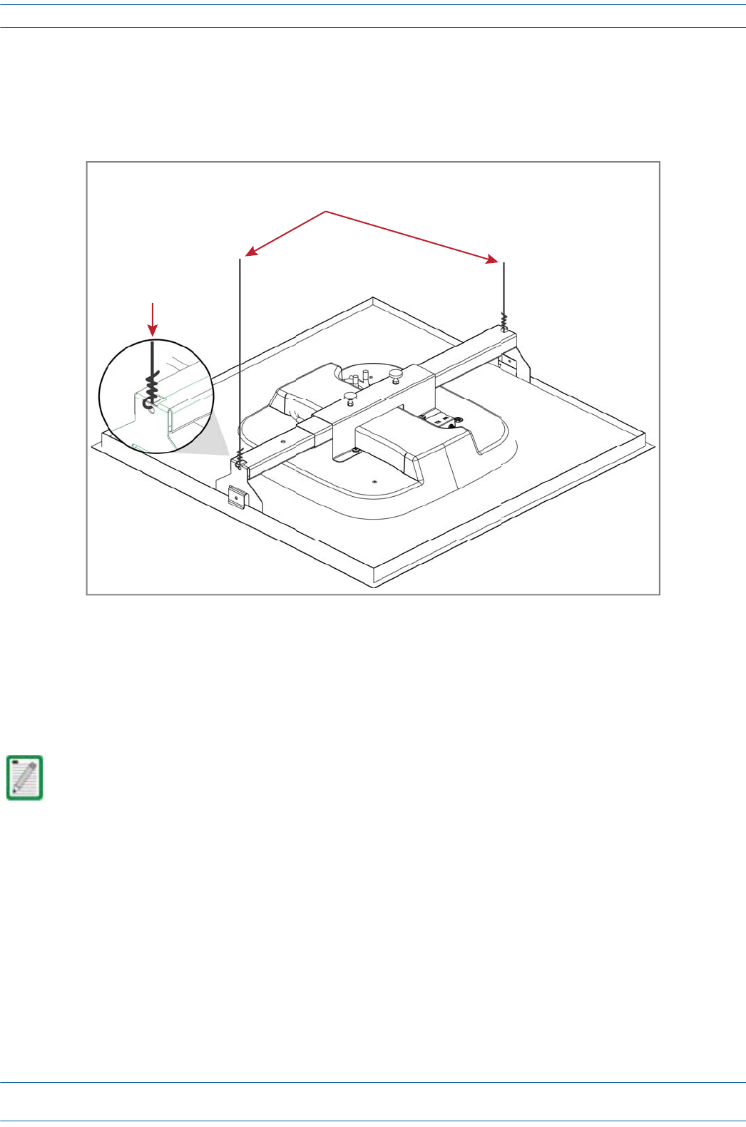
M0201AA ION®-E Series Hardware Installation Guide
© June 2017 CommScope, Inc. Page 57
Installing UAPs
12 Forsafety,theinstallationofhangerwirestoattachtheUAP'sTwo-PartSlidingSupportBarsto
permanentceilingstructuresisrecommended.
Attachhangerwires,accordingtolocalbuildingcodesfromtheroofstructuretotheholesatendsofthe
UAP'sTwo-PartSlidingSupportBars,asshownbelow.
Mounting a UAP Using a UAP Quick Release Ceiling Mount Kit
UNRESOLVED: What is the PN for this kit?
TheUAPquickreleaseceilingmountkitisdesignedtobeinstalledinastandard60cmx60cm(2'x2')
suspendedceilinggrid.Ifthegriduses120cmx60cm(4'x2')ceilingtiles,addanadditionalcross-runner
(cross-tee)tothemainrunnertosupporttheunit.Aminimumoverheadclearanceof70cmisrecommended.
UAPwallmountingkit7683181-00isalsoavailablefromCommScopeformountingaUAPtoawallorhard
ceiling.
Required Tools for a Quick Release Ceiling Mount Kit
•8mmmetrictorquewrenchtosecuretheGuide-Lockpinsandthumbscrewlocknuts
•Cuttingtooltocutopenceilingtile
For information on mounting a UAP to a ceiling using the standard UAP ceiling mount, go to "Using the
UAP Ceiling Mount Assembly (PN 7683182-00)” on page 53.
Hanger wires connected to the pre-drilled holes
in the Two-Part Sliding Support Bars
Exploded view
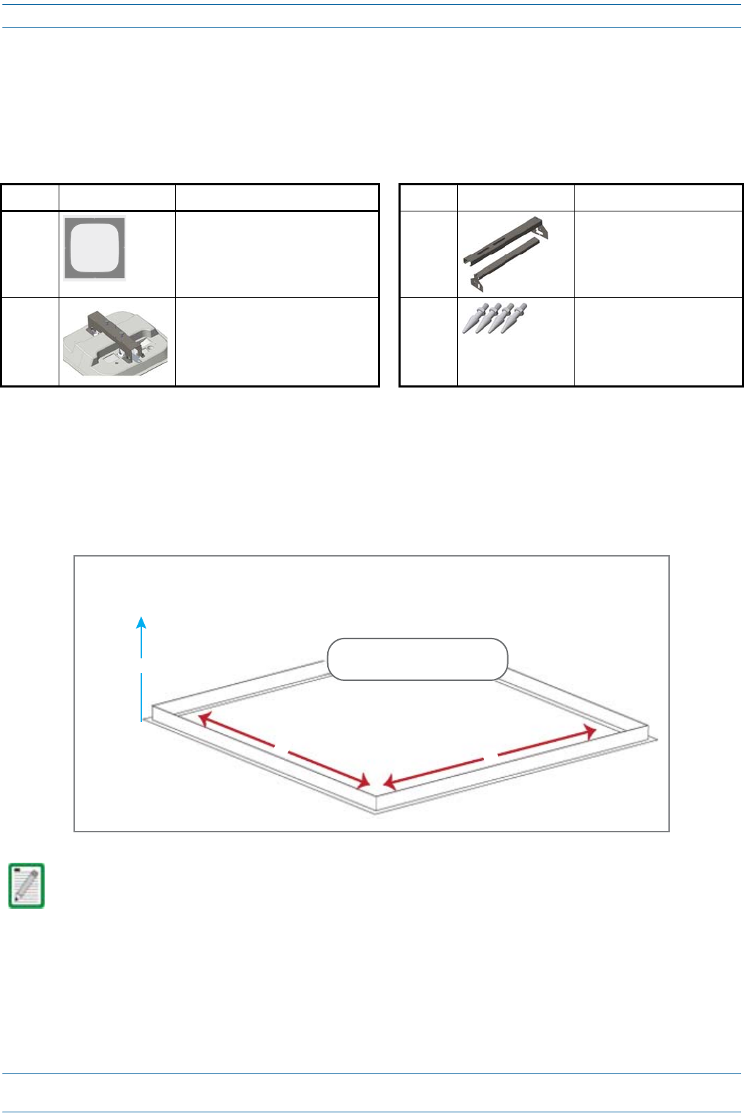
ION®-E Series Hardware Installation Guide M0201AA
Page 58 © June 2017 CommScope, Inc.
Installing UAPs
Unpack and Inspect the Quick Release Ceiling Mount Kit
1Inspecttheexterioroftheshippingcontainer(s)forevidenceofroughhandlingthatmayhavedamaged
thecomponentsinthecontainer.
2Unpackeachcontainerwhilecarefullycheckingthecontentsfordamageandverifywiththepackingslip.
Overview of Using a Quick Release Ceiling Mount Kit
TheUAPQuickReleaseCeilingMountkitisdesignedtobeinstalledinastandard60cmx60cm(2'x2')
suspendedceilinggrid.Ifthegriduses120cmx60cm(4'x2')ceilingtiles,addanadditionalcross-runner
(cross-tee)tothemainrunnertosupporttheunit.Aminimumoverheadclearanceof70cmisrecommended,
asshownbelow.
Table 6-3. Quick Release Ceiling Mount Kit (PN ???????-00)
Quantity Component Description Quantity Component Description
1Template 1 each Left and Right UAP Recess Bar
1 each UAP Recess Shroud with Mounting
Bracket
4Guide Lock Pins
It is the responsibility of the installer to ensure that the UAP is safely installed.
Recommended
overhead clearance
is 70 cm (27.6 in)
Y
X
Ceiling grid
60 cm min.
(23.6 in min.)
60 cm min. - 76 cm max.
(23.6 in min. - 29.9 in max.)
Z