Ants IOT technology MYBLE Bluetooth module User Manual
Shenzhen Ants IOT technology Co., Ltd Bluetooth module Users Manual
Users Manual

Shenzhen Ants IOT technology Co., Ltd
Page:1/1
Product Name: Bluetooth module
Model No.:BPS_MODULE
OEM/Integrators Installations User Manual
(Note: The module is limited to OEM installation ONLY; The OEM integrator is responsible for ensuring that the end-user has no
manual instructions to remove or install module)
Shenzhen Ants IOT technology Co., Ltd
Page:1/2
1. General
1.1 Introduction
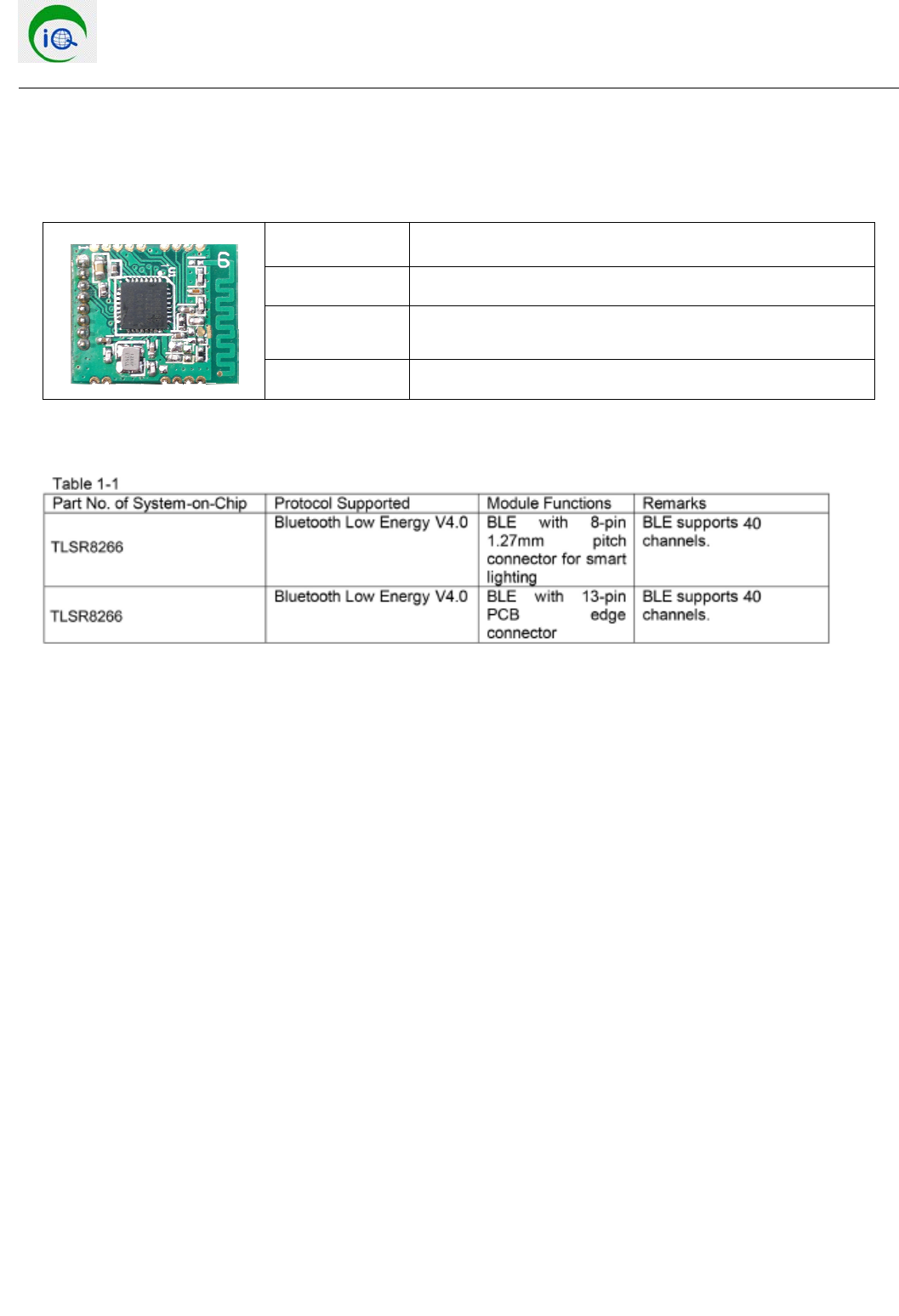
Product Name Bluetooth module
Model No:BPS_MODULE
Function:Bluetooth low energy BLE module supporting mesh
networking
Control Method:APP control、remote control
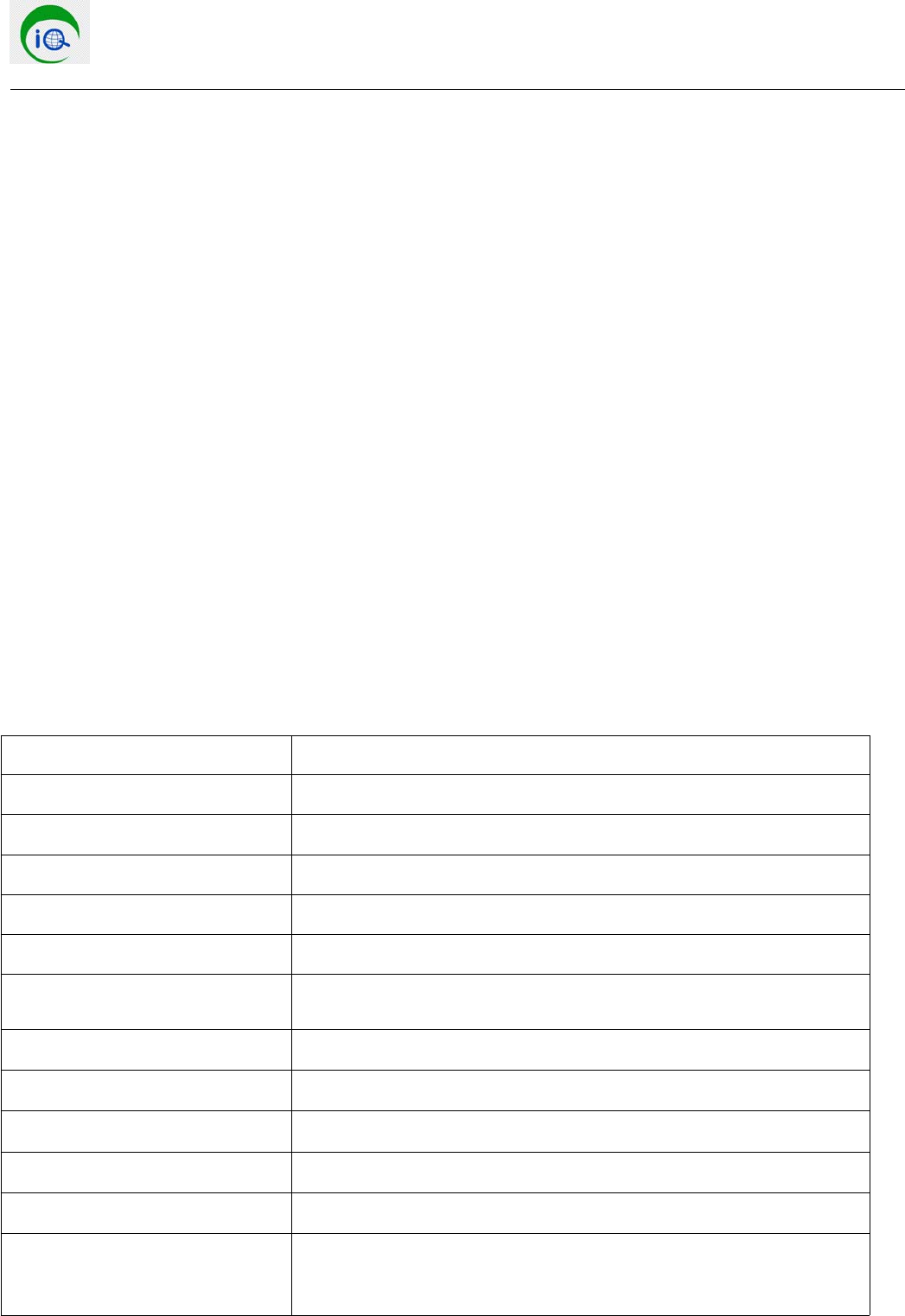
1.2 Module support diversities based on connectors used as shown in Table 1-1
1.3 Features
Bluetooth specification V4.0 with mesh networking supported
Embed32-bithighperformanceRISCMCUwithclockupto48MHZ
Compact package size (18x15x2.8mm)
Host Controller interface(HCI) over UART,I2C and USE in full speed
Class I supported with 8dBm maximum TX power
Built-in Flash up to 512Kbytes, system clock
Built-in 16KB SRAM
Module Size 18 x 15 x 2.8mm
Receiving Sensitivity -92dBm,Maximum transmit power up to +8dBm,Data transfer rate up to 2Mbps
Conform to FCC, CE, ROSH and other certification
1.4 Applications
Set Top Box
Consumer Electronics: TV, home theatre system, blue-ray player/Recorder
Human-interface Devices: Remote Control, Mouse, Keyboard
LED Lighting
Smart AC switch
Health Care
Sports and leisure Equipment
Mobile Phone Accessories
Smart Metering
USB Dongle
Wearable devices
Other Hands-Free Devices
Shenzhen Ants IOT technology Co., Ltd
Page:1/3
2. Characteristics
2.1 Electrical characteristics
Module size 18 x 15 x 2.8mm
RF Transmitting power level In-system-programmable flash 512k bytes
RAM 16Kbytes x 32 bits
Date Rate 250kbps,500kbps,1Mbps,2Mbps
Antenna PCB Printed Antenna: Gain 0dBi
Operational RF distance 30m in the open field without RF interference
Physical connector (1) 1x8 1.27mm pitch through terminal
(2) 13-pin PCB board edge connetcor
Operational Voltage 1.9V to 3.6V
Operating ambient temperature range TA -40℃—+55℃
Reference oscillator for timer Built in
Security:128-bit AES encryption
Serial date interfance UART /I2C/ USB
EMC Europe: ETSI EN 300 328 and EN 300 440 Class 2
USA: FCC CFR47 Part 15
Japan: ARIB STD-T66
Shenzhen Ants IOT technology Co., Ltd
Page:1/4
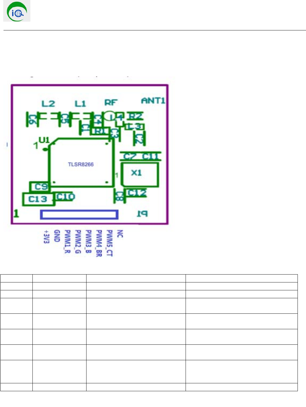
2.2 Module outline specifications
Pin No Pin Name Pin Type Description
1 3V3 Power supply 1.9V to 3.6V
2 GND Ground
3 PWM1_R I/O(PWM output can be supported to
control Red color LED)
Configurable I/O Port(Or PWM output
port)
4 PWM2_G I/O(PWM output can be supported to
control Green color LED)
Configurable I/O Port(Or PWM output
port)
5 PWM3_B I/O(PWM output can be supported to
control Blue color LED)
Configurable I/O Port(Or PWM output
port)
6 PWM4_BR I/O(PWM output can be supported to
control brightness of white LED)
Configurable I/O Port(Or PWM output
port)
7 PWM5_CT I/O(PWM output can be supported to
control color temperature of warm
white color LED)
Configurable I/O Port(Or PWM output
port)
8 GPIO 2/NC I/O Configurable I/O Port
Shenzhen Ants IOT technology Co., Ltd
Page:1/5
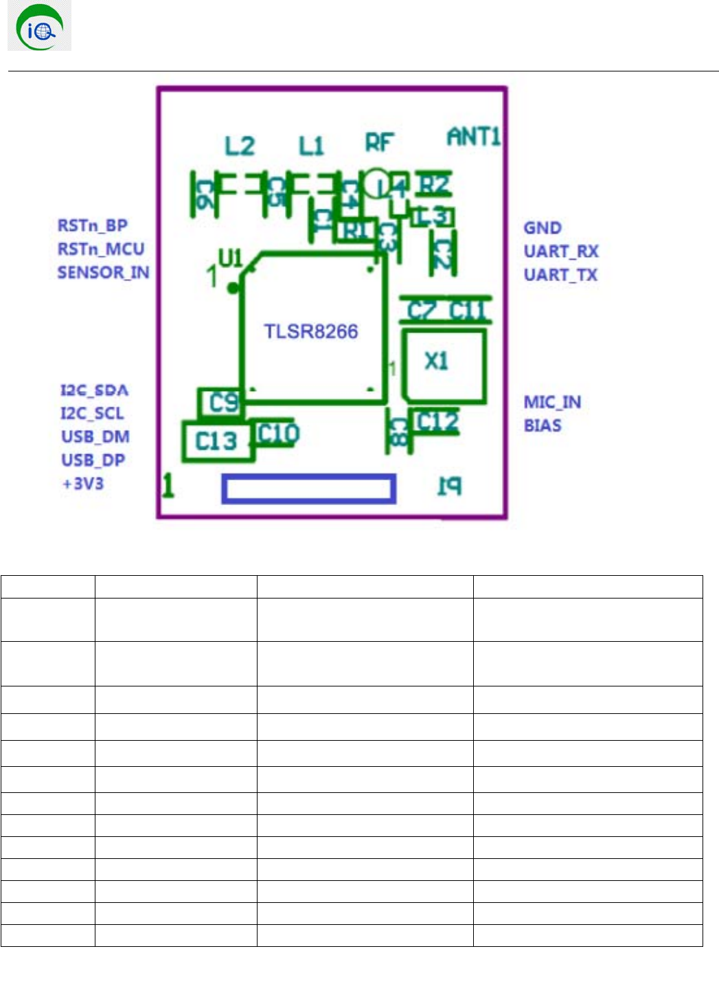
Pin No Pin Name Pin Type Description
1 RSTn_BP Digital I/O Reset BLE module by host
MCU,active low
2RSTn_MCUDigital I/O Reset host MCU by BLE module,
active low
3Sensor_in Digital I/O External sensor signal input
4I2C_SDA Digital I/O I2C date
5I2C_SCL Digital I/O I2C clock
6USB_DM Digital I/O USC N for module
7 USB_DP Digital I/O USB P for module
8 +3V3 Power supply
9 BIAS Microphone bias
10 MIC_IN Microphone input signal
11 UART_TX Digital I/O UART_TXD
12 UART_RX Digital I/O UART_TXD
13 GND Ground
Shenzhen Ants IOT technology Co., Ltd
Page:1/6
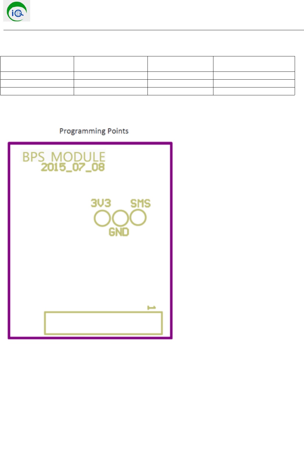
3. Module flash memory programming(in circuit)
Test point No for
programming
Signal name of test point Description of test point Diameter of test point
TP1 3V3 +3.3V power supply 1.0mm
TP2 GND Ground 1.0mm
TP3 SMS SMS 1.0mm

Shenzhen Ants IOT technology Co., Ltd
Page:1/7
FCC Warning:
If the FCC identification number is not visible when the module is installed inside another device, then the
outside of the device into which the module is installed must also display a label referring to the enclosed
module. This exterior label can use wording such as the following:
“Contains Transmitter Module FCC ID: 2AH7Z-MYBLE ”
when the module is installed inside another device, the user manual of this device must contain below
warning statements;
1. This device complies with Part 15 of the FCC Rules. Operation is subject to the following two
conditions:
(1) This device may not cause harmful interference.
(2) This device must accept any interference received, including interference that may cause undesired
operation.
2. Changes or modifications not expressly approved by the party responsible for compliance could void the
user's authority to operate the equipment.
FCC statement:
This device complies with part 15 of the FCC Rules. Operation is subject to the following two conditions: (1) This device
may not cause harmful interference, and (2) this device must accept any interference received, including interference that
may cause undesired operation.
Any Changes or modifications not expressly approved by the party responsible for compliance could void the user's
authority to operate the equipment.
This equipment has been tested and found to comply with the limits for a Class B digital device, pursuant to part 15 of the
FCC Rules. These limits are designed to provide reasonable protection against harmful interference in a residential
installation. This equipment generates uses and can radiate radio frequency energy and, if not installed and used in
accordance with the instructions, may cause harmful interference to radio communications. However, there is no guarantee
that interference will not occur in a particular installation. If this equipment does cause harmful interference to radio or
television reception, which can be determined by turning the equipment off and on, the user is encouraged to try to correct
the interference by one or more of the following measures:
-Reorient or relocate the receiving antenna.
-Increase the separation between the equipment and receiver.
-Connect the equipment into an outlet on a circuit different from that to which the receiver is connected.
-Consult the dealer or an experienced radio/TV technician for help.
That separate approval is required for all other operating configurations, including portable configurations with respect to
Part 2.1093 and different antenna configurations.
This product is mounted inside of the end product only by professional installers OEM. They use this module with
changing the power and control signal setting by software of end product within the scope of this application. End user
can not change this setting.
The equipment complies with RF exposure limits. This module is limited to installation in mobile or fixed applications.
The antenna used for this transmitter must not be co-located or operating in conjunction with any other antenna or
transmitter.
This equipment complies with the FCC RF radiation exposure limits set forth for an uncontrolled environment. This
equipment should be installed and operated with a minimum distance of 20cm between the radiator and any part of your
body.