Aperto Networks R3000-A1 WLAN Base Station and Subscriber Unit User Manual PacketWave 1000 Manual Rev A July 2001
Aperto Networks WLAN Base Station and Subscriber Unit PacketWave 1000 Manual Rev A July 2001
Contents
- 1. Subscriber user manual
- 2. Base Station user manual 1 of 2
- 3. Base Station user manual 2 of 2
Base Station user manual 1 of 2

PACKETWAVE
Fixed Wireless Broadband Access System
PACKETWAVE 1000 SERIES
BASE STATION EQUIPMENT
Installation, Configuration, and Operation Manual
070-20000340-01
Rev. A, July 2001
PacketWave 1000 Manual
©Copyright 2001 by Aperto Networks
All rights reserved.
Specifications subject to change.
Aperto, PacketWave, WaveCenter, RapidBurst, OptimaLink,
and ServiceQ are trademarks of Aperto Networks.
All other trademarks used herein are the property of their respective owners.
Aperto Networks
1637 South Main Street
Milpitas, CA 95035 USA
Phone: 408.719.9977
Fax: 408.719.9970
www.apertonet.com

iii070-20000330-01
REGULATORY INFORMATION
PART 15
This device complies with Part 15 of the FCC Rules. Operation is subject to the following two con-
ditions:
1) this device may not cause harmful electromagnetic interference, and
2) this device must accept any interference received includinginterference that may cause undes-
ired operations.
FCC NOTICE: Radio and Television Interference
The PacketWave 100 Series Subscriber Equipment has been tested and found to comply with the lim-
its for a Class B digital device, pursuant to Part 15 of the FCC Rules. These limits are designed to
provide reasonable protection against harmful interference in a residential installation. This equipment
generates, uses, and can radiate radio frequency energy and, if not installed and used according to the
instructions, may cause harmful interference to radio communications. However, there is no guarantee
that interference will not occur in a particular installation. If this equipment does cause harmful inter-
ference to radio or television reception, which is found by turning the equipment off and on, the user
is encouraged to try to correct the interference by one or more of the following measures:
• Reorient or relocate the receiving antenna.
• Increase the separation between the equipment or device.
• Connect the equipment to an outlet other than the receiver's.
• Consult a dealer or an experienced radio/TV technician for assistance.
RF Exposure Notice
The installer shall mount all transmit antennas so as to comply with the limits for human
exposure to radio frequency (RF) fields per paragraph 1.1307 of FCC regulations. The
FCC requirements incorporate limits for Maximum Permissible Exposure (MPE) in
terms of electric field strength, magnetic field strength, and power density
CAUTION
To comply with FCC RF exposure requirements, antennas used for this device must be
installed to provide a separation distance of at least 1.5m from all persons.

v070-20000340-01 Rev A
TABLE OF
CONTENTS
Table of Contents
PREFACE
Scope of This Manual . . . . . . . . . . . . . . . . . . . . . . . . . . . . . . . . . . . . . . . . . . . . . . . . . . . . ix
Conventions Used in This Manual . . . . . . . . . . . . . . . . . . . . . . . . . . . . . . . . . . . . . . . . . . x
Intended Audience for this Manual . . . . . . . . . . . . . . . . . . . . . . . . . . . . . . . . . . . . . . . . . . x
General Cautions and Warnings . . . . . . . . . . . . . . . . . . . . . . . . . . . . . . . . . . . . . . . . . . . . xi
CHAPTER 1. QUICKSTART GUIDE
Planning, Site Preparation, and Configuration . . . . . . . . . . . . . . . . . . . . . . . . . . . . . . . . . 1-2
Installing and Starting Base Station Equipment . . . . . . . . . . . . . . . . . . . . . . . . . . . . . . . . 1-5
Installing and Starting Subscriber Equipment . . . . . . . . . . . . . . . . . . . . . . . . . . . . . . . . . . 1-6
CHAPTER 2. PACKETWAVE SYSTEM OVERVIEW
Conceptual Overview of the PacketWave System . . . . . . . . . . . . . . . . . . . . . . . . . . . . . . 2-1
Cell Size, Capacity, and Scalability . . . . . . . . . . . . . . . . . . . . . . . . . . . . . . . . . . . 2-3
Multiple Frequency Bands . . . . . . . . . . . . . . . . . . . . . . . . . . . . . . . . . . . . . . . . . . 2-3
IP-Based System . . . . . . . . . . . . . . . . . . . . . . . . . . . . . . . . . . . . . . . . . . . . . . . . . 2-4
Range of Backhaul Options . . . . . . . . . . . . . . . . . . . . . . . . . . . . . . . . . . . . . . . . . 2-4
Subscriber and Network Management . . . . . . . . . . . . . . . . . . . . . . . . . . . . . . . . . 2-4
Technological Innovations . . . . . . . . . . . . . . . . . . . . . . . . . . . . . . . . . . . . . . . . . . 2-5
RapidBurst . . . . . . . . . . . . . . . . . . . . . . . . . . . . . . . . . . . . . . . . . . . . . . . 2-5
OptimaLink . . . . . . . . . . . . . . . . . . . . . . . . . . . . . . . . . . . . . . . . . . . . . . . 2-5
ServiceQ . . . . . . . . . . . . . . . . . . . . . . . . . . . . . . . . . . . . . . . . . . . . . . . . . 2-5
Base Station (Cell Site) Equipment . . . . . . . . . . . . . . . . . . . . . . . . . . . . . . . . . . . . . . . . . . 2-6
Base Station Unit . . . . . . . . . . . . . . . . . . . . . . . . . . . . . . . . . . . . . . . . . . . . . . . . . 2-6
Multiple Base Station Units . . . . . . . . . . . . . . . . . . . . . . . . . . . . . . . . . . . 2-7
Base Station Radios and Antennas . . . . . . . . . . . . . . . . . . . . . . . . . . . . . . . . . . . 2-7
Subscriber Site Equipment . . . . . . . . . . . . . . . . . . . . . . . . . . . . . . . . . . . . . . . . . . . . . . . . 2-8
The PacketWave System’s IP Network . . . . . . . . . . . . . . . . . . . . . . . . . . . . . . . . . . . . . . 2-10
Address Assignment . . . . . . . . . . . . . . . . . . . . . . . . . . . . . . . . . . . . . . . . 2-13
Clustering Wireless Interfaces . . . . . . . . . . . . . . . . . . . . . . . . . . . . . . . . 2-13
SU-to-SU Bridging . . . . . . . . . . . . . . . . . . . . . . . . . . . . . . . . . . . . . . . . . . 2-13
Multiple Subnets on a Wireless Subsystem (WSS) . . . . . . . . . . . . . . . . 2-14
Variable-Length Subnets (VLSM) . . . . . . . . . . . . . . . . . . . . . . . . . . . . . . 2-15
Servers . . . . . . . . . . . . . . . . . . . . . . . . . . . . . . . . . . . . . . . . . . . . . . . . . . . . . . . . . 2-16

vi070-20000340-01 Rev A
TABLE OF CONTENTS
DHCP Server . . . . . . . . . . . . . . . . . . . . . . . . . . . . . . . . . . . . . . . . . . . . . 2-16
TFTP Server . . . . . . . . . . . . . . . . . . . . . . . . . . . . . . . . . . . . . . . . . . . . . . 2-16
SNTP Server . . . . . . . . . . . . . . . . . . . . . . . . . . . . . . . . . . . . . . . . . . . . . . 2-17
DNS Server . . . . . . . . . . . . . . . . . . . . . . . . . . . . . . . . . . . . . . . . . . . . . . . 2-17
SMTP Server . . . . . . . . . . . . . . . . . . . . . . . . . . . . . . . . . . . . . . . . . . . . . . 2-17
System Log Server (Syslog) . . . . . . . . . . . . . . . . . . . . . . . . . . . . . . . . . . 2-17
SNMP Manager . . . . . . . . . . . . . . . . . . . . . . . . . . . . . . . . . . . . . . . . . . . . 2-17
Configuration and Management Software . . . . . . . . . . . . . . . . . . . . . . . . . . . . . . . . . . . . . 2-19
WaveCenter Configuration Manager . . . . . . . . . . . . . . . . . . . . . . . . . . . . . . . . . . 2-19
Web-Based GUI . . . . . . . . . . . . . . . . . . . . . . . . . . . . . . . . . . . . . . . . . . . . . . . . . . 2-20
SNMP Agents . . . . . . . . . . . . . . . . . . . . . . . . . . . . . . . . . . . . . . . . . . . . . . . . . . . . 2-20
Command Line Interface . . . . . . . . . . . . . . . . . . . . . . . . . . . . . . . . . . . . . . . . . . . 2-20
Service Offerings and QoS . . . . . . . . . . . . . . . . . . . . . . . . . . . . . . . . . . . . . . . . . . . . . . . . 2-21
Concepts of PacketWave Service Level Definition . . . . . . . . . . . . . . . . . . . . . . . 2-21
Assigning Service Levels . . . . . . . . . . . . . . . . . . . . . . . . . . . . . . . . . . . . . . . . . . . 2-21
CHAPTER 3. SYSTEM PLANNING
Cell Site Considerations . . . . . . . . . . . . . . . . . . . . . . . . . . . . . . . . . . . . . . . . . . . . . . . . . . 3-1
Subscriber Site Considerations . . . . . . . . . . . . . . . . . . . . . . . . . . . . . . . . . . . . . . . . . . . . . 3-4
IP Planning: Addressing and Subnetting . . . . . . . . . . . . . . . . . . . . . . . . . . . . . . . . . . . . . . 3-5
Configuration Planning . . . . . . . . . . . . . . . . . . . . . . . . . . . . . . . . . . . . . . . . . . . . . . . . . . . 3-5
Service Level Planning . . . . . . . . . . . . . . . . . . . . . . . . . . . . . . . . . . . . . . . . . . . . . 3-6
CHAPTER 4. INSTALLING BASE STATION UNITS
Mounting . . . . . . . . . . . . . . . . . . . . . . . . . . . . . . . . . . . . . . . . . . . . . . . . . . . . . . . . . . . . . . 4-1
Front-Panel Connections . . . . . . . . . . . . . . . . . . . . . . . . . . . . . . . . . . . . . . . . . . . . . . . . . 4-2
Connecting the Radios to the BSU . . . . . . . . . . . . . . . . . . . . . . . . . . . . . . . . . . . 4-2
Connecting the Backhaul Link . . . . . . . . . . . . . . . . . . . . . . . . . . . . . . . . . . . . . . . 4-2
Interconnecting Multiple BSUs at a Site . . . . . . . . . . . . . . . . . . . . . . . . . . . . . . . . 4-4
Connecting an External Reference Clock . . . . . . . . . . . . . . . . . . . . . . . . . . . . . . 4-6
Connecting to the Alarm/Control Relay Switch . . . . . . . . . . . . . . . . . . . . . . . . . . 4-7
Connecting to the RS-232 Craft Port . . . . . . . . . . . . . . . . . . . . . . . . . . . . . . . . . . 4-8
Connecting Power . . . . . . . . . . . . . . . . . . . . . . . . . . . . . . . . . . . . . . . . . . . . . . . . . . . . . . . 4-8
AC Power . . . . . . . . . . . . . . . . . . . . . . . . . . . . . . . . . . . . . . . . . . . . . . . . . . . . . . . 4-9
Fuse . . . . . . . . . . . . . . . . . . . . . . . . . . . . . . . . . . . . . . . . . . . . . . . . . . . . 4-9
DC Power . . . . . . . . . . . . . . . . . . . . . . . . . . . . . . . . . . . . . . . . . . . . . . . . . . . . . . . 4-10
CHAPTER 5. INSTALLING RADIOS AND ANTENNAS
Installing the Antenna Mounting System . . . . . . . . . . . . . . . . . . . . . . . . . . . . . . . . . . . . . . 5-1
Mounting the Antennas and Radios . . . . . . . . . . . . . . . . . . . . . . . . . . . . . . . . . . . . . . . . . 5-2
Running the Radio Cables . . . . . . . . . . . . . . . . . . . . . . . . . . . . . . . . . . . . . . . . . . . . . . . . 5-3
Radio to Antenna . . . . . . . . . . . . . . . . . . . . . . . . . . . . . . . . . . . . . . . . . . . . . . . . . 5-3
Radio to Base Station . . . . . . . . . . . . . . . . . . . . . . . . . . . . . . . . . . . . . . . . . . . . . 5-3
Radio Signal Connection . . . . . . . . . . . . . . . . . . . . . . . . . . . . . . . . . . . . . 5-5
Control Connection . . . . . . . . . . . . . . . . . . . . . . . . . . . . . . . . . . . . . . . . . 5-6
DC Voltage Insertion for Extra-Long Cables . . . . . . . . . . . . . . . . . . . . . . . . . . . . 5-7

vii070-20000340-01 Rev A
TABLE OF CONTENTS
CHAPTER 6. BSU AND SUBSCRIBER
CONFIGURATION
Installing the WaveCenter Configuration Manager . . . . . . . . . . . . . . . . . . . . . . . . . . . . . . 6-1
How the WaveCenter Configuration Manager Works . . . . . . . . . . . . . . . . . . . . . . . . . . . . 6-3
BSU and Subscriber Branches . . . . . . . . . . . . . . . . . . . . . . . . . . . . . . . . . . . . . . 6-3
Configuration Screen Formats . . . . . . . . . . . . . . . . . . . . . . . . . . . . . . . . . . . . . . . 6-4
Managing Configuration Files . . . . . . . . . . . . . . . . . . . . . . . . . . . . . . . . . . . . . . . 6-6
Opening and Loading Files . . . . . . . . . . . . . . . . . . . . . . . . . . . . . . . . . . . 6-6
Saving Files . . . . . . . . . . . . . . . . . . . . . . . . . . . . . . . . . . . . . . . . . . . . . . . 6-6
Downloading Configuration Files . . . . . . . . . . . . . . . . . . . . . . . . . . . . . . 6-7
Using the WaveCenter Configuration Manager . . . . . . . . . . . . . . . . . . . . . . . . . . . . . . . . 6-8
Base Station Configuration . . . . . . . . . . . . . . . . . . . . . . . . . . . . . . . . . . . . . . . . . . . . . . . . 6-9
Configuring Wireless Subsystems (WSS) . . . . . . . . . . . . . . . . . . . . . . . . . . . . . . 6-10
Frame Parameters . . . . . . . . . . . . . . . . . . . . . . . . . . . . . . . . . . . . . . . . . 6-11
Channel Parameters . . . . . . . . . . . . . . . . . . . . . . . . . . . . . . . . . . . . . . . . 6-12
Radio Parameters . . . . . . . . . . . . . . . . . . . . . . . . . . . . . . . . . . . . . . . . . . 6-14
Multiple Subnet Parameters . . . . . . . . . . . . . . . . . . . . . . . . . . . . . . . . . . 6-14
CD Packet Parameters . . . . . . . . . . . . . . . . . . . . . . . . . . . . . . . . . . . . . . 6-14
Preamble Parameters . . . . . . . . . . . . . . . . . . . . . . . . . . . . . . . . . . . . . . . 6-14
Configuring the Main Base Station Parameters . . . . . . . . . . . . . . . . . . . . . . . . . . 6-17
General Parameters . . . . . . . . . . . . . . . . . . . . . . . . . . . . . . . . . . . . . . . . 6-17
Server IP Parameters . . . . . . . . . . . . . . . . . . . . . . . . . . . . . . . . . . . . . . . 6-19
Bridging/Clustering Parameters . . . . . . . . . . . . . . . . . . . . . . . . . . . . . . . 6-19
Configuring SNMP Parameters . . . . . . . . . . . . . . . . . . . . . . . . . . . . . . . . . . . . . . 6-19
Configuring Email Alert Parameters . . . . . . . . . . . . . . . . . . . . . . . . . . . . . . . . . . . 6-23
Subscriber Configuration . . . . . . . . . . . . . . . . . . . . . . . . . . . . . . . . . . . . . . . . . . . . . . . . . . 6-24
Configuring Subscriber System Parameters . . . . . . . . . . . . . . . . . . . . . . . . . . . . 6-25
Configuring Subscriber SNMP Parameters . . . . . . . . . . . . . . . . . . . . . . . . . . . . . 6-26
Configuring Packet Filters . . . . . . . . . . . . . . . . . . . . . . . . . . . . . . . . . . . . . . . . . . 6-27
Configuring Service Flows . . . . . . . . . . . . . . . . . . . . . . . . . . . . . . . . . . . . . . . . . . 6-28
Configuring Service Flow Classifiers . . . . . . . . . . . . . . . . . . . . . . . . . . . . . . . . . . 6-32
Configuring Routing Functions . . . . . . . . . . . . . . . . . . . . . . . . . . . . . . . . . . . . . . . 6-35
Configuring Subscriber Email Alerts . . . . . . . . . . . . . . . . . . . . . . . . . . . . . . . . . . 6-36
Configuring NAT Routing . . . . . . . . . . . . . . . . . . . . . . . . . . . . . . . . . . . . . . . . . . . 6-37
Configuring the Subscriber Indoor Unit’s DHCP Server . . . . . . . . . . . . . . . . . . . . 6-38
Other Configuration Methods . . . . . . . . . . . . . . . . . . . . . . . . . . . . . . . . . . . . . . . . . . . . . . 6-39
CHAPTER 7. NETWORK CONFIGURATION
AND START-UP
Servers . . . . . . . . . . . . . . . . . . . . . . . . . . . . . . . . . . . . . . . . . . . . . . . . . . . . . . . . . . . . . . . 7-1
Required and Recommended Servers . . . . . . . . . . . . . . . . . . . . . . . . . . . . . . . . . 7-2
Optional Servers . . . . . . . . . . . . . . . . . . . . . . . . . . . . . . . . . . . . . . . . . . . . . . . . . 7-3
Preparing the TFTP Server . . . . . . . . . . . . . . . . . . . . . . . . . . . . . . . . . . . . . . . . . 7-4
Configuring the DHCP Server . . . . . . . . . . . . . . . . . . . . . . . . . . . . . . . . . . . . . . . 7-4
System Start-Up . . . . . . . . . . . . . . . . . . . . . . . . . . . . . . . . . . . . . . . . . . . . . . . . . . . . . . . . 7-5
Adding Base Station Units and/or Subscribers . . . . . . . . . . . . . . . . . . . . . . . . . . . . . . . . . 7-5
Other Configuration Methods . . . . . . . . . . . . . . . . . . . . . . . . . . . . . . . . . . . . . . . . . . . . . . 7-6

ix070-20000340-01 Rev A
PREFACE
This manual is part of the documentation for the PacketWave fixed broadband
wireless system for delivering high-speed subscriber services. The PacketWave
documentation set includes:
•PacketWave 1000 Base Station Unit Installation, Configuration, and Operation
Manual: part number 070-20000340-0x
•PacketWave 100 Series Subscriber Equipment Installation and Operation Man-
ual: part number 070-20000330-0x
SCOPE OF THIS MANUAL
This manual documents Release 1, Phase 1 (R1P1) of the PacketWave System
This manual provides the following information:
•A QuickStart section for rapidly placing a PacketWave System in operation.
•A conceptual overview of the PacketWave System.
•Descriptions of the PacketWave hardware components, including base station
and subscriber equipment.
•Descriptions of the PacketWave software components, including configuration
programs, management interfaces, installation utilities, and monitoring/diag-
nostic functions.
•System and site planning information.
•Complete installation instructions for base station equipment.
•System configuration, management, and diagnostic procedures.
Installation and operating instructions for subscriber equipment (CPE) are provided in
the PacketWave 100 Series Subscriber Equipment Installation and Operation manual.
PREFACE
x070-20000340-01 Rev A
CONVENTIONS USED IN THIS MANUAL
PacketWave manuals represent special kinds of text as follows:
•Files names and URLs are represented in italics, with variables described inside
angle brackets. For example, if the URL http://<IP address>/bsu.htm is refer-
enced, you will replace the variable <IP address> with the appropriate real IP
address.
•Management interface text is represented by a bold font: for example, the
Generate Config File button.
•Labels on equipment are represented in a bold sans serif font: for example, the
Control connector.
WARNING: This format is used to indicate the possibility of personal injury
or serious damage to equipment.
CAUTION: This format is used to indicate the possibility of system or equip-
ment operation problems.
Items of special importance will be formatted and marked by a pointing-hand
icon, as this paragraph is.
INTENDED AUDIENCE FOR THIS MANUAL
This manual is intended for system designers and planners, base station installers,
system operators, and others requiring or desiring information about the PacketWave
System. It provides information specific to the PacketWave system, but cannot and
should not be considered a tutorial on relevant technologies and practices.
It is expected that system designers and planners are knowledgeable about radio
communications, cellular communication systems, and IP networks. Tutorials on
these subjects are beyond the scope of this manual, and are readily available in pub-
lished and on-line materials.
Installation of radio equipment involves numerous factors, such as lightning and
weather protection, requiring considerable expertise. It is assumed that equipment
installers are professionals with knowledge of the principles and standard practices
and procedures of cell site installation, with all relevant safety requirements, and with
applicable local building codes.

xi070-20000340-01 Rev A
PREFACE
GENERAL CAUTIONS AND WARNINGS
Observe the following when installing or operating any PacketWave System compo-
nents.
All installation, including equipment mounting and cabling, should be performed
by trained microwave radio technicians familiar with usual and customary
practices and procedures.
Always use quality components—including cables, connectors, mounts, etc.—spe-
cifically rated for your particular environmental conditions and system
performance requirements.
Always use appropriate tools, and follow the instructions of the tool
manufacturers.
Observe all applicable local building codes.
Observe all customary and mandatory safety requirements when installing and
operating PacketWave equipment.
Because Aperto cannot be responsible for improper installation or use of its equip-
ment, failure to follow these and other published cautions and warnings may void your
equipment warranty.

PREFACE
xii070-20000340-01 Rev A

1–1070-20000340-01 Rev A
1
QUICKSTART GUIDE
This chapter outlines the basic procedure for installing a PacketWave System and put-
ting it into operation. It identifies the minimal requirements for getting the system up
and running.
WARNING: This QuickStart Guide assumes that installation procedures will
be performed by qualified professionals following all safety and
other requirements and acting in accordance with standard prac-
tices and procedures. Failure to meet safety requirements and/or
non-standard practices and procedures could result in personal
injury and/or damage to equipment.
All of the instructions presented in this chapter are discussed in more detail in subse-
quent chapters of this manual and in the PacketWave 100 Series Subscriber Equip-
ment Installation and Operation manual.

CHAPTER 1. QUICKSTART GUIDE
1–2070-20000340-01 Rev A
PLANNING, SITE PREPARATION, AND CONFIGURATION
Before you begin installing the PacketWave equipment, make sure you properly plan
the overall system and individual sites.
Step 1. Determine and Prepare Locations
A. Make sure that the base station is located such that it can communicate with sub-
scribers.
•Cell sector width may be 60º or 90º, depending on the antenna chosen.
•Distance between base station and subscriber site may be up to 5 miles for line-
of-sight or near-line-of sight communications, or up to 1 mile for non-line-of-
site communications.
B. Make sure that the base station site includes a proper mounting structure for the
radios and antennas, and an indoor location for the Base Station Unit. Maximum
cable length is 165 feet (50 m) without dc insertion from an external source.
C. Make sure all subscriber sites have an appropriate radio/antenna support or
mounting location. Maximum cable length between subscriber Indoor Units
(bridge/routers) and Outdoor Units (radio/antennas) is 165 feet (50 m) without dc
insertion from an external source.
Step 2. Define IP Networking
A. Each cell sector is served by a separate wireless subsystem (WSS) in the Base
Station Unit. The WSS wireless interface will be the gateway for all subscribers
it serves, which typically define a single subnet. Determine the WSS interface
(gateway) address based on the available IP address space and desired subnetting.
NOTE: The PacketWave System supports VLSM.
B. The Base Station Unit requires a DHCP server from which it and subscribers
receives IP addresses and other basic configuration information, and a TFTP
server from which they download configuration files.
i. The DHCP server, or a DHCP relay agent pointing to it, must be on the
same subnet as the BSU’s backhaul interface for the BSU to locate the
DHCP server.
ii. The address of the TFTP server is provided by the DHCP server, so may be
any reachable IP address.
C. If SNTP (time), SMTP (mail), SNMP, and/or Syslog servers are to be imple-
mented, their IP addresses will be required during BSU configuration.

1–3070-20000340-01 Rev A
CHAPTER 1. QUICKSTART GUIDE
Step 3. Create BSU Configuration File(s)
A. Load and run the WaveCenter Configuration Manager program (provided on CD).
NOTE: The program can be run on the TFTP server or another computer from which
the files can be downloaded to the TFTP server. The Configuration Manager runs on
Windows 98, NT, or 2000 Professional; Linux; or Sun Solaris.
B. From the opening screen, click on the BSU icon to open the BSU Configuration
Manager. For WSS 1:
i. Go to the WSS — Multiple Subnets menu and specify the WSS IP
Address and WSS Subnet Mask (mandatory).
NOTE: If multiple subnets are to be implemented for the WSS, click on the new
instance icon and repeat the step above until all subnets are defined.
ii. Go to the WSS — Channel menu and specify the Channel Center
Frequency (mandatory).
iii. If desired, configure any optional WSS parameters as described in Chapter
6 of this manual.
iv. Save the configuration by clicking the Generate WSS Config button and
following the prompts.
v. For an additional WSS, click on the new instance icon on the WSS — Mul-
tiple Subnets menu, which will increment the WSS number (Host ID).
Then return to step i above. When all WSS are configured, proceed to the
step C.
C. Go to the MAIN — General menu and specify the Base Station Unit’s MAC
Address.
D. If desired, configure any optional BSU parameters (MAIN, SNMP, and
ALERTS menus) as described in Chapter 6 of this manual.
E. When all configuration has been completed, generate the BSU configuration file
by clicking on the Generate BSU Config button and following the prompts. Save
the config file with a name uniquely linking it to the BSU; Aperto recommends
the default format bsc_<MACaddress>.cfg.
F. Close the BSU Configuration Manager. If there are additional BSUs to configure,
return to step B.

CHAPTER 1. QUICKSTART GUIDE
1–4070-20000340-01 Rev A
Step 4. Create Subscriber Configuration Files
A. From the WaveCenter Configuration Manager’s opening screen, click on the
subscriber Indoor Unit icon to open the subscriber (CPE) Configuration Manager
option.
i. Go to the System menu and specify the MAC address, CPE Mode and
CPE Model (mandatory).
ii. If the CPE Mode is NAT, you may go to the NAT menu and configure as
desired. However, the defaults will work for basic operation.
iii. If the CPE Mode is Router, you may go to the Router menu and configure
as desired. However, the defaults will work for basic operation. (Standard
routing is not supported in R1P1.)
B. If desired, configure any other optional subscriber parameters as described in
Chapter 6 of this manual.
C. When all configuration has been completed, generate the subscriber configuration
file by clicking on the Generate Configuration File button and following the
prompts. Save the config file with a name uniquely linking it to the subscriber
Indoor Unit; Aperto recommends the default format cpe_<MACaddress>.cfg.
D. Close the CPE Configuration Manager. If there are additional subscribers to
configure, return to step A.
Step 5. Configure the TFTP and DHCP Servers
A. Download all BSU and subscriber configuration files to the default TFTP direc-
tory on the TFTP server.
B. Configure the DHCP server for the following:
•IP address and subnet mask for TFTP server, and for other servers as desired.
•Range(s) of assignable addresses, with subnet masks and gateway addresses.
•BSU MAC address and the name of the corresponding configuration file to be
found on the TFTP server.
•For each subscriber Indoor Unit, its MAC address and the name of the corre-
sponding configuration file to be found on the TFTP server.
NOTE: If desired, different DHCP servers can be defined for the BSU and for sub-
scribers.
C. Make sure that the DHCP and TFTP servers are running.

1–5070-20000340-01 Rev A
CHAPTER 1. QUICKSTART GUIDE
INSTALLING AND STARTING BASE STATION EQUIPMENT
The steps in this section outline the physical installation of the base station equipment.
(See Chapters 4 and 5 of this manual for details.)
Step 6. Install Base Station Radios and Antennas
A. Mount the PacketWave radios and antennas on the antenna mast or other support
structure using the mounting brackets supplied, or other brackets as required by
the support structure. Observe minimum distances between antennas and maxi-
mum radio-to-antenna distances.
B. Connect the radio’s RF jumper cables to the appropriate connectors on the
antenna.
C. Install radio signal and control cables between each radio and the Base Station
Unit location. Label the cable ends to prevent misconnections.
-Radio signal cable (RG6, 75 ohm, quad shield coaxial, male F connectors)
-Radio control cable (shielded outdoor Cat 5, male RJ45 connectors)
The Radio Control interface on the Base Station has the same physical appearance
as the 10/100Base-T interface. Make sure you connect to the right one.
Step 7. Install the Base Station Unit
A. Mount the Base Station Unit in an equipment rack, allowing for adequate air flow
around and through the unit.
B. Connect the radio signal and control cables from the outdoor radios to the proper
ports on the BSU front panel.
NOTE: No other connections to the front panel are necessary for a site with a single
BSU. See Chapter 4 for discussions of optional connections and/or multiple BSUs.
C. Connect 120 V ac or -48 V dc to the rear panel connector, as appropriate.
Connecting power will cause the Base Station Unit to boot up, locate the DHCP
server and obtain basic configuration information from it, then download its full
configuration file from the TFTP server.
NOTE: If power is connected before the DHCP server is configured and the BSU’s
configuration file is available in the TFTP server, or if either of the servers is
unreachable, the BSU will power up in standby mode. It will need to be rebooted
when the servers are fully configured and reachable.

CHAPTER 1. QUICKSTART GUIDE
1–6070-20000340-01 Rev A
After the first successful loading of the BSU configuration file from the TFTP server,
the configuration will be stored in nonvolatile memory on the BSU. Thus, if the BSU
is rebooted when the TFTP server is unreachable, the BSU will operate with its exist-
ing configuration rather than going into standby mode.
INSTALLING AND STARTING SUBSCRIBER EQUIPMENT
The steps in this section outline the physical installation and initialization of equip-
ment at the subscriber site. See the PacketWave 100 Series Subscriber Equipment
Installation and Operation manual for details.
Step 8. Prepare for Installation
A. Before visiting the subscriber’s site:
i. Make sure that the necessary system configuration has taken place, as
described in the PacketWave 1000 Base Station Unit Installation, Configu-
ration, and Operation manual.
ii. Make sure that the DHCP and TFTP servers are running.
iii. Verify that the subscriber configuration file has been created and saved on
the TFTP server.
iv. Verify that the DHCP server has been configured with the subscriber’s IP
and MAC addresses and its configuration file name.
B. At the subscriber’s site:
i. Identify the location for the Indoor Unit (bridge/router).
ii. Identify an appropriate location for mounting the Outdoor Unit, where it can
be pointed at the base station with the least possible obstruction
iii. Determine the cable path between the Indoor Unit and the Outdoor Unit.
Maximum cable length is 165 feet (50 m).
Step 9. Install the Outdoor Unit (Radio/Antenna)
A. If a mounting pole or other support is to be employed, install it in the chosen loca-
tion, following standard procedures and local building codes.
The Outdoor Unit’s mounting bracket accommodates diameters of 1.5 inches, 2
inches, or 5 cm.
B. Mount the Outdoor Unit to the support or to the building.
1–7070-20000340-01 Rev A
CHAPTER 1. QUICKSTART GUIDE
Step 10. Install the Indoor Unit (Bridge/Router)
A. To start, in most cases, the Indoor Unit should be temporarily placed close to the
Outdoor Unit to facilitate antenna alignment process. When the installation of the-
Outdoor Unit is complete, move the Indoor Unit to its permanent location.
Make sure the Indoor Unit is located near an electrical power outlet or power
extension cord will be needed.
WARNING: For proper cooling, the Indoor Unit must be installed in the
upright position, with adequate air flow around and through it.
B. Assuming that the Indoor Unit is located at a temporary location, run spare radio
signal and control cables between the Outdoor and Indoor Units.
-Radio signal cable (quad shield coaxial, male F connectors) — Radio RF
connectors on the Outdoor and Indoor Units.
-Radio control cable (shielded outdoor Cat 5, male RJ45 connectors) —
Radio Control connectors on the Outdoor and Indoor Units.
The Radio Control interface on the Indoor Unit has the same physical appearance
as the 10/100Base-T interface. Make sure you connect to the right one.
Step 11. Initialize the Subscriber Equipment
A. Connect the power module between the Indoor Unit and a wall outlet.
B. Perform antenna alignment procedure (see the PacketWave 100 Subscriber Equip-
ment manual, or the addendum on this subject).
C. If the Indoor Unit is located at a temporary location, move the Indoor Unit to its
permanent location.
WARNING: For proper cooling, the Indoor Unit must be installed in the
upright position, with adequate air flow around and through it.
D. Use the permanent radio signal and control cables to connect the Outdoor Unit to
the Indoor Unit.
-Radio signal cable (RG6, 75 ohm, quad shield coaxial, male F connectors)
— between Radio RF connectors on the Outdoor and Indoor Units.
-Radio control cable (shielded outdoor Cat 5, male RJ45 connectors) —
between Radio Control connectors on the Outdoor and Indoor Units.

CHAPTER 1. QUICKSTART GUIDE
1–8070-20000340-01 Rev A
Step 12. Configure Subscriber Hosts
A. Connect the subscriber’s computer(s) to the 10/100Base-T interface on the Indoor
Unit, using a straight Ethernet cable for connection to a hub or a crossover Ether-
net cable for connection directly to a computer.
B. Typically, the only other thing necessary to connect a subscriber host computer
to the PacketWave network and beyond is to configure the host’s TCP/IP to obtain
its IP address using DHCP. Instructions should be available using the computer’s
online help

2–1070-20000340-01 Rev A
2
PACKETWAVE SYSTEM OVERVIEW
This chapter provides a description of the PacketWave Broadband Multiservice Wire-
less Access System, including system architecture, functionality, features, benefits,
and hardware and software components.
CONCEPTUAL OVERVIEW OF THE PACKETWAVE SYSTEM
Aperto Networks’ PacketWave System is a next-generation fixed broadband wireless
access solution that dramatically increases capacity and coverage while reducing
deployment cost and time to market. It is a cellular system consisting of the

CHAPTER 2. PACKETWAVE SYSTEM OVERVIEW
2–2070-20000340-01 Rev A
Figure2-1 PacketWave System Elements

2–3070-20000340-01 Rev A
CHAPTER 2. PACKETWAVE SYSTEM OVERVIEW
Cell Size, Capacity, and Scalability
Aperto’s advanced wireless technologies support a wide range of cell requirements,
and make PacketWave an exceptionally scalable solution. PacketWave cell specifica-
tions include:
•Cell radius can easily reach 5 miles (8 km) with line-of-site transmission paths,
or about 1 mile (1.6 km) with obstructed paths.
•Each Base Station Unit can support up to 250 subscribers per sector, with a
maximum of six sectors.
•A cell can employ multiple Base Station Units. Thus, a single cell can serve
thousands of subscribers.
•The bandwidth capacity for a Base Station Unit is 120 Mbps, based on a max-
imum raw bit rate of 20 Mbps per sector.
•Subscriber data rates can be individually configured from 384 kbps to 10 Mbps;
with bursts to 20 Mbps.
•The ratio of downstream to upstream traffic can be adjusted between 90%
downstream/10% upstream and 90% upstream/10% downstream.
The PacketWave System ensures that a wireless network can grow to thousands of
subscribers in urban or suburban areas through high frequency reuse and dense
multicell deployment. Combining high frequency reuse with advanced interference
management and mitigation techniques, the PacketWave System conserves valuable
spectrum by covering extensive geographical areas with a minimum number of
channels.
As the number of subscribers and the bandwidth needs in a cell increase, new sectors
can be added, and multiple PacketWave 1000 Base Station Units can be stacked to
provide additional bandwidth using multiple channels per sector. To extend service
offerings geographically, a service provider simply deploys additional cells.
Multiple Frequency Bands
The PacketWave System can be deployed in the standard frequency bands used vari-
ously throughout the world for licensed or unlicensed wireless broadband networking.
The PacketWave 1000 Base Station Unit can support PacketWave radios and antennas
operating in 2.5 GHz MMDS, 3.5 GHz FWA, 5.3 GHz, and 5.8 GHz U-NII bands
with no physical or software reconfiguration. Similarly, any PacketWave 100 Series
Subscriber Indoor Unit (bridge/router) can support the same range of frequency bands.

CHAPTER 2. PACKETWAVE SYSTEM OVERVIEW
2–4070-20000340-01 Rev A
IP-Based System
The PacketWave System leads the industry in the implementation of advanced IP fea-
tures and services. Packet filtering, DHCP snooping, and ARP snooping conserve
bandwidth for subscriber traffic. Support for IP RIP routing, multiple subnets per sec-
tor, Variable-Length Subnet Mask (VLSM), and Classless Internet Domain Routing
(CIDR) ensure complete control of IP address management and network configura-
tion. PacketWave Series 100 Subscriber Indoor Units support bridging, IP routing,
and NAT for flexible deployment.
Because the PacketWave System is based on IP end-to-end and IP networking skills
and resources are relatively common, the PacketWave solution helps service providers
to control costs, expand service options, expedite configuration, simplify connection
to the Internet, and minimize time to market. The ubiquity of IP also allows native
support for value-added Internet applications such as VPN, web hosting, and video-
conferencing.
Range of Backhaul Options
The PacketWave 1000 Base Station Unit offers both flexible and cost-effective solu-
tions to connect to backhaul networks. In its basic configuration, PacketWave 1000
supports 10/100 Mbps Ethernet. This enables the PacketWave 1000 to connect
directly to an Ethernet-based MAN or, through an external router, to a variety of
broadband network technologies. Through future plug-in modules, other backhaul
options, such as ATM, will be directly supported. In addition, external optical or high-
capacity wireless backhaul such as millimeter wave technology can be implemented.
Where other backhaul options are not available, one of the Base Station Unit’s wire-
less channels can provide a link to a backhaul network.
Whatever the backhaul option, quality of service (QoS) is maintained throughout the
network using either IP Differentiated Services (DiffServ), ATM Service Categories,
or MPLS.
Subscriber and Network Management
The PacketWave System simplifies subscriber and network management by using
GUI-based tools, standard protocols, and industry-standard platforms. One of these
tools is the highly-scalable, Java-based WaveCenter™ Configuration Manager, which
automates the subscriber provisioning process. In addition to the WaveCenter
Configuration Manager, the PacketWave System also includes Web-based and
SNMP-compliant network management software for configuration, fault, perfor-
mance, and security management.

2–5070-20000340-01 Rev A
CHAPTER 2. PACKETWAVE SYSTEM OVERVIEW
Technological Innovations
At the heart of PacketWave's revolutionary performance are three innovative Aperto
Networks technologies: RapidBurst™, OptimaLink™, and ServiceQ™.
RapidBurst
RapidBurst technology enables the PacketWave System to achieve exceptionally low
latency and high spectral efficiency. Advanced Time Division Multiple Access
(TDMA) burst mode ensures maximum flexibility and efficiency in both upstream
and downstream transmissions. Adaptive Time Division Duplexing (TDD) allows
operation in a single channel anywhere in the spectrum. Dynamic bandwidth alloca-
tion assigns time slots and packet sizes depending on specific traffic flows. With
RapidBurst, the PacketWave System provides up to 120 Mbps of bandwidth per cell
with one base station.
OptimaLink
OptimaLink technology individually optimizes the reliability and throughput of each
Subscriber wireless channel by dynamically adjusting up to ten PHY- and MAC-layer
parameters. The result is increased coverage, extending broadband services to
subscribers who would otherwise be unreachable due to obstructed-line-of-sight or
non-line-of-sight conditions.
ServiceQ
ServiceQ technology provides different quality of service (QoS) levels to subscribers
on a flow-by-flow basis enabling differentiated service offerings and effective man-
agement of service level agreements (SLAs). Various service levels can be defined in
three service classes—Constant Bit Rate (CBR), Committed Information Rate (CIR),
and Best Effort (BE). The percentage of bandwidth allocated to each service class is
adjustable depending on the mix of service offerings.
ServiceQ supports high-quality video and telephony applications. Each service flow
can be associated with a specific host or application and can be assigned to any service
class, so application-specific services with QoS can be offered.
CHAPTER 2. PACKETWAVE SYSTEM OVERVIEW
2–6070-20000340-01 Rev A
BASE STATION (CELL SITE) EQUIPMENT
PacketWave base station equipment includes the PacketWave 1000 Base Station Unit
and associated radios and antennas.
Base Station Unit
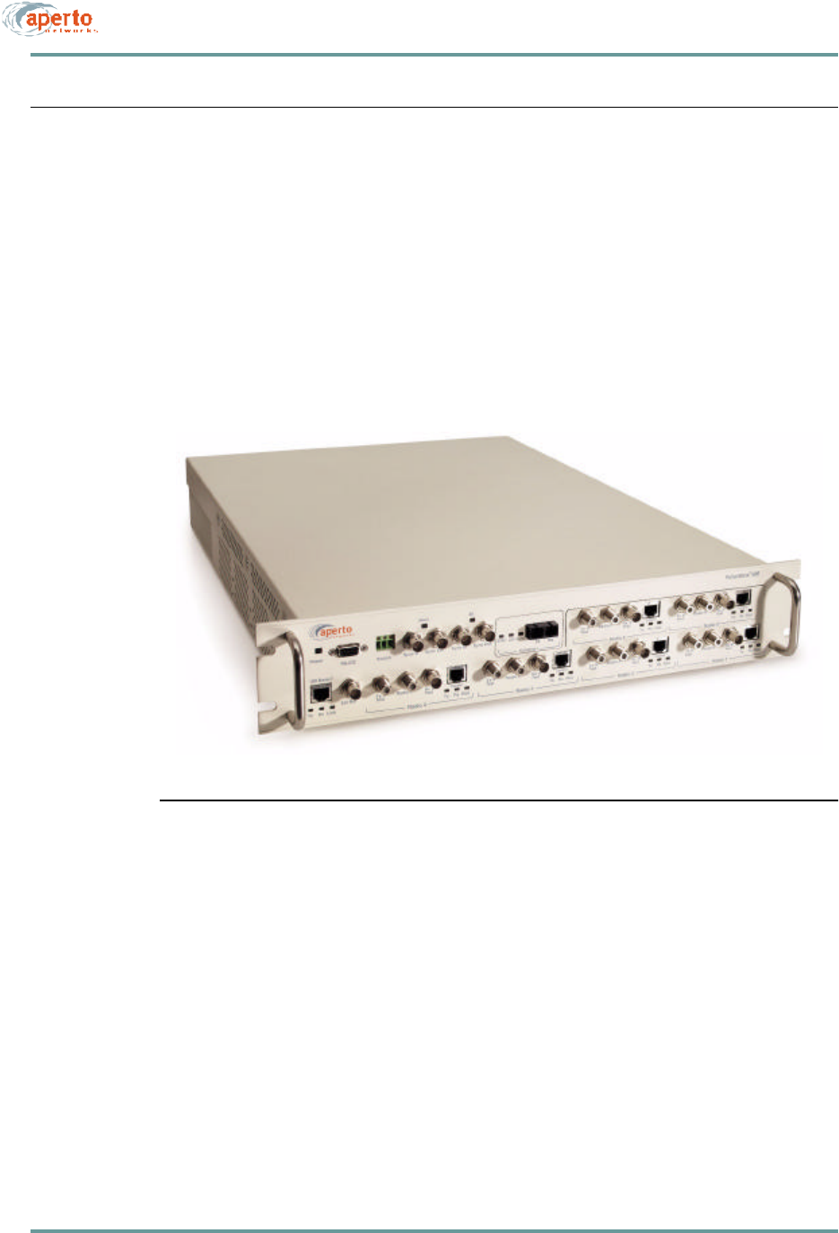
The PacketWave 1000 Base Station Unit, shown in Figure2-2, is a single rack-
mounting controller unit which supports any of the PacketWave System radio and
backhaul options. There are two models, one with an ac power supply and one with
a dc power supply.
Figure2-2 PacketWave 1000 Base Station Unit
In the basic configuration pictured, the PacketWave 1000 includes:
•Four built-in wireless interfaces for connection to radios and their associated
antennas.
•A 10/100Base-TX Ethernet backhaul interface.
•Synchronization interfaces for multiple colocated Base Station Units.
•A local RS-232 craft management port.
•An external clock interface.
•A dry-contact relay which can be configured to operate a local alarm device or
to control redundant equipment such as a backup radio and antenna.

2–7070-20000340-01 Rev A
CHAPTER 2. PACKETWAVE SYSTEM OVERVIEW
•Two slots for plug-in modules.
-One slot will support a dual wireless interface unit, allowing a total of six
wireless interfaces in the Base Station Unit.
-The second slot will support an alternative backhaul interface. Modules sup-
porting additional backhaul options, including ATM, are under development.
Multiple Base Station Units
Subscriber density and bandwidth requirements may combine to exceed the capacity
of a single Base Station Unit. Part of the scalability built into the PacketWave System
is the ability to colocate and link multiple Base Station Units at a cell site. Through
the use of different center frequencies within the system’s frequency band, sectors can
be overlaid within the cell to serve additional subscribers, providing a virtually unlim-
ited growth path.
To coordinate the Time Division Multiple Access (TDMA) and Time Division
Duplexing (TDD) on which the PacketWave wireless communication is based, it is
necessary for all Base Station Units in a cell to be synchronized in terms of signal
framing and time slot identification. Sync ports on the Base Station Unit allow all
units to share the same framing, with inputs for a main and alternate BSU to provide
the framing signal.
Base Station Radios and Antennas
PacketWave base station radios and antennas deliver the benefits of a single-source,
thoroughly-tested base station package.
Radios and antennas are available for the following frequency bands:
•2.5 GHz MMDS
•3.5 GHz FWA
•5.3 GHz U-NII
•5.8 GHz U-NII
There are also different antenna models available for 60° and 90° sectors.
Radios and antennas are designed for mounting outdoors on tubular antenna masts or
similar supports. Details are provided in Chapter 5.
CHAPTER 2. PACKETWAVE SYSTEM OVERVIEW
2–8070-20000340-01 Rev A
SUBSCRIBER SITE EQUIPMENT
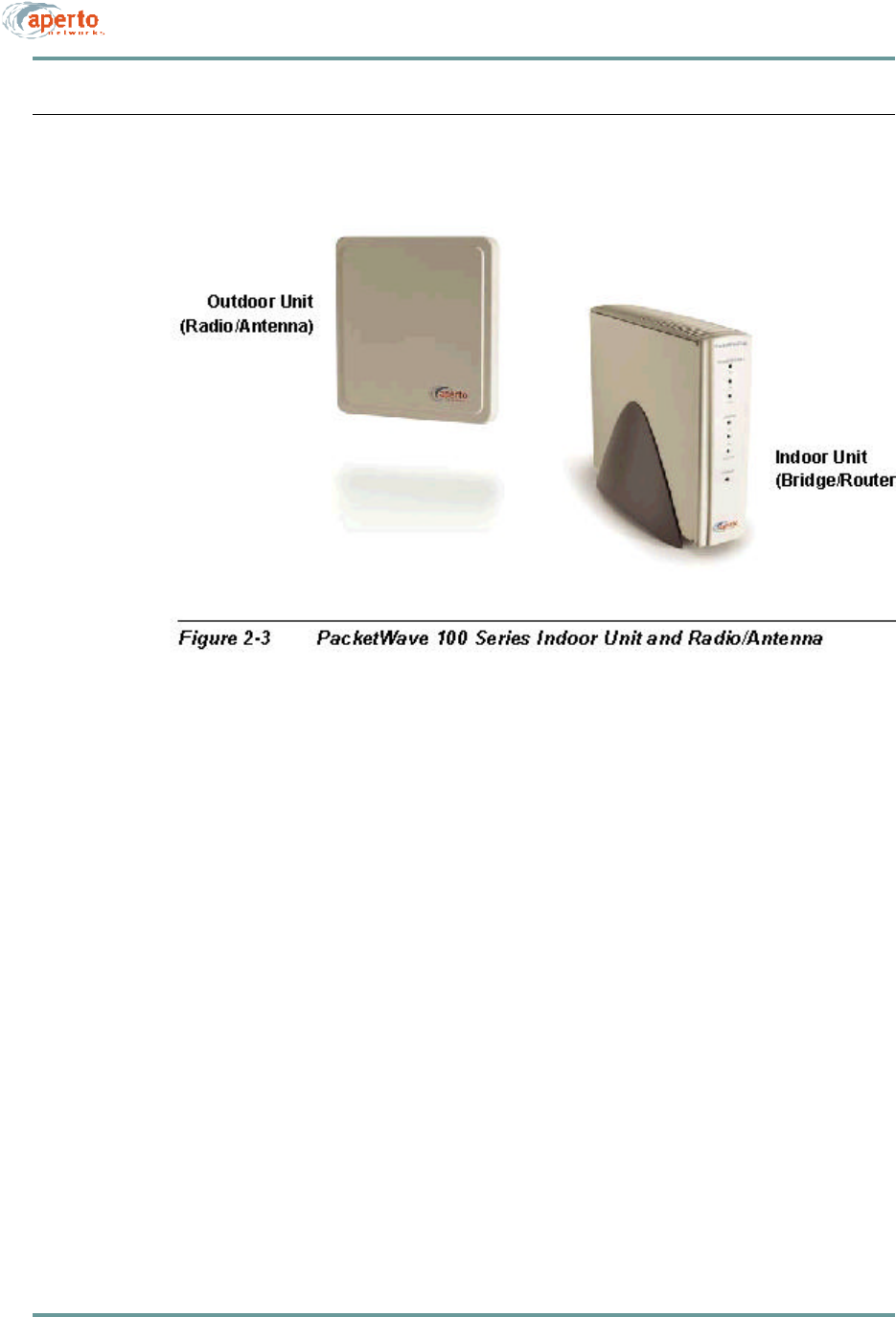
PacketWave equipment installed at the subscriber site consists of an subscriber Indoor
Unit (a bridge/router between the wireless subnet and the subscriber’s computer or
LAN), and an outdoor integrated radio/antenna unit. The two units are illustrated in
Figure2-3.
There are four models of radios, for support of different frequency bands:
•2.5 GHz MMDS
•3.5 GHz FWA
•5.3 GHz U-NII
•5.8 GHz U-NII
Radio/antenna units vary in size, depending on the frequency band. Each subscriber
Indoor Unit can support any of the integrated radio/antenna units. (Of course, the
radio’s frequency band must match that employed at the base station.)
The radio/antenna unit is usually installed on the subscriber’s roof or under the eave,
mounted either on a pole or to a flat surface. It is also possible to mount a radio/
antenna unit in a window if a suitable transmission path is available.
2–9070-20000340-01 Rev A
CHAPTER 2. PACKETWAVE SYSTEM OVERVIEW
There are three models of the Indoor Unit: the PacketWave 110, 120, and 130. R1P1
supports only the PacketWave 130, which can function as either a bridge or a NAT
router as illustrated in Figure2-4.
Figure2-4 PacketWave 100 Series Subscriber Indoor Units
Bridging Mode
NAT Router Mode

CHAPTER 2. PACKETWAVE SYSTEM OVERVIEW
2–10070-20000340-01 Rev A
THE PACKETWAVE SYSTEM’S IP NETWORK
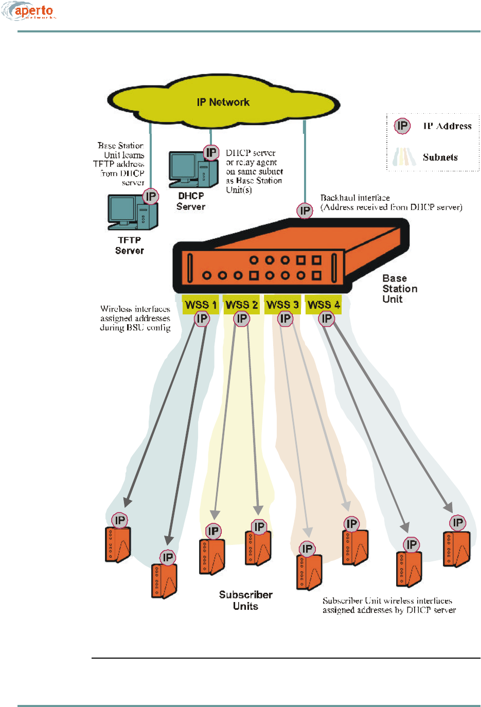
The PacketWave System uses IP for the backhaul channel and the wireless channels.
Overall, the system has the following network architecture, as shown in Figure2-5.
•The Base Station Unit’s backhaul channel is part of a subnet which includes:
-A gateway to the outside world (Internet or private network).
-Access to a DHCP server (either the DHCP server or a DHCP relay agent
must be on the same subnet as the BSU’s backhaul interface).
-Access to a TFTP server identified by the DHCP server.
•Each wireless interface is the gateway for a subnet comprising itself and the
subscriber Indoor Units with which it communicates, and perhaps some or all
of the hosts at the subscriber sites.
NOTE: A wireless interface can be configured for multiple subnets, if desired. Also,
two or more wireless interfaces can be “clustered” in the same subnet. These options
are discussed in detail later in this section.
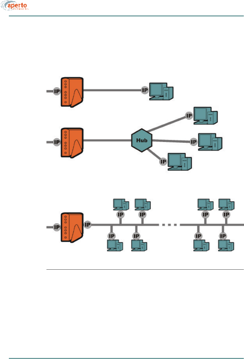
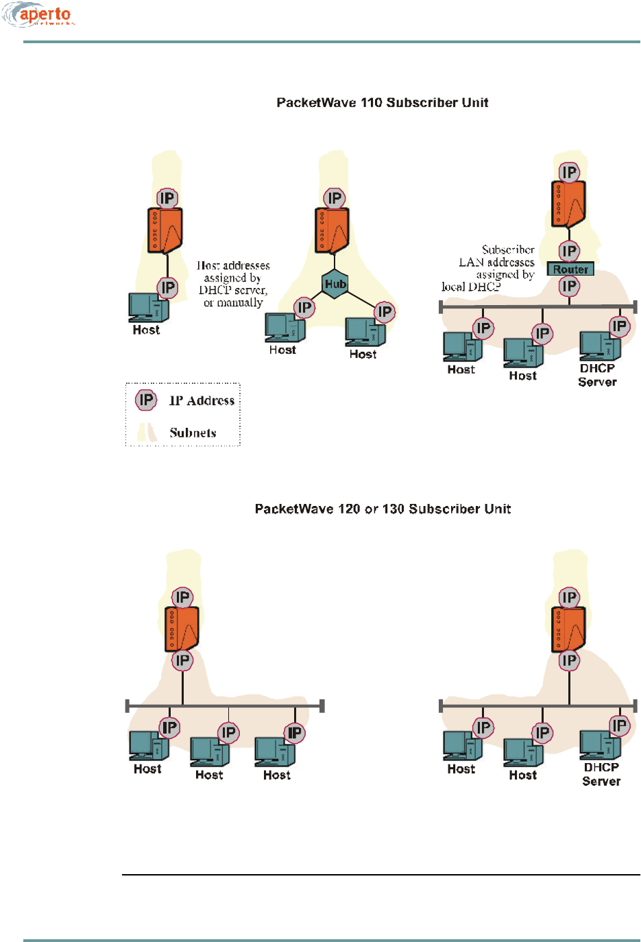
•Subnets may be implemented at subscriber sites. Figure2-6 shows various
options.
2–11070-20000340-01 Rev A
CHAPTER 2. PACKETWAVE SYSTEM OVERVIEW
Figure2-5 PacketWave System IP Architecture
CHAPTER 2. PACKETWAVE SYSTEM OVERVIEW
2–12070-20000340-01 Rev A
Figure2-6 PacketWave Subscriber Indoor Unit and Host IP Addressing

2–13070-20000340-01 Rev A
CHAPTER 2. PACKETWAVE SYSTEM OVERVIEW
Address Assignment
The PacketWave System supports DHCP (Dynamic Host Configuration Protocol),
which manages IP address assignment for most interfaces in the PacketWave network.
In the configuration of the DHCP server, the PacketWave System IP addresses
must be fixed—i.e., reserved for the specific units; they cannot be dynamically
assigned.
Specifically, PacketWave System IP addresses are distributed as follows:
•The Base Station Unit receives the IP address of its backhaul interface from the
DHCP server for its subnet.
•The Base Station Unit’s wireless interfaces (WSS) are assigned IP addresses as
part of the BSU configuration (using the WaveCenter Configuration Manager).
•Subscriber Indoor Units receive the IP addresses of their wireless interfaces
from the DHCP server, via a DHCP relay agent in the Base Station Unit.
•Subscriber hosts can receive IP addresses in a variety of ways (see Figure2-6):
-From the BSU’s DHCP server, via DHCP relay agents in the subscriber
Indoor Unit and the Base Station Unit.
-From a DHCP server included in the subscriber Indoor Unit.
-From a DHCP server on the subscriber’s subnet.
-Using NAT (Network Address Translation), provided by the PacketWave
Subscriber Indoor Unit or by a NAT router on the subscriber’s subnet.
-By manual entry at the hosts.
Clustering Wireless Interfaces
To enhance flexibility in the use of a particular IP address space, the PacketWave
1000 Base Station Unit allows multiple wireless interfaces to be assigned to the same
subnet. This is done during BSU configuration using the WaveCenter Configuration
Manager.
SU-to-SU Bridging
To make communication within the wireless subnets more efficient, the PacketWave
1000 Base Station Unit supports bridging between subscribers on the same subnet.
SU-to-SU bridging is enabled or disabled during BSU configuration using the
WaveCenter Configuration Manager.
CHAPTER 2. PACKETWAVE SYSTEM OVERVIEW
2–14070-20000340-01 Rev A
Multiple Subnets on a Wireless Subsystem (WSS)
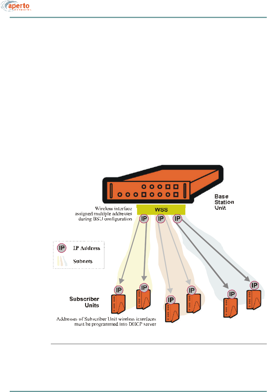
To enable one wireless interface to support subscribers for two or more service pro-
viders, the PacketWave 1000 Base Station Unit allows multiple subnets to be assigned
to the same wireless interface. This is done during BSU configuration using the Wave-
Center Configuration Manager.
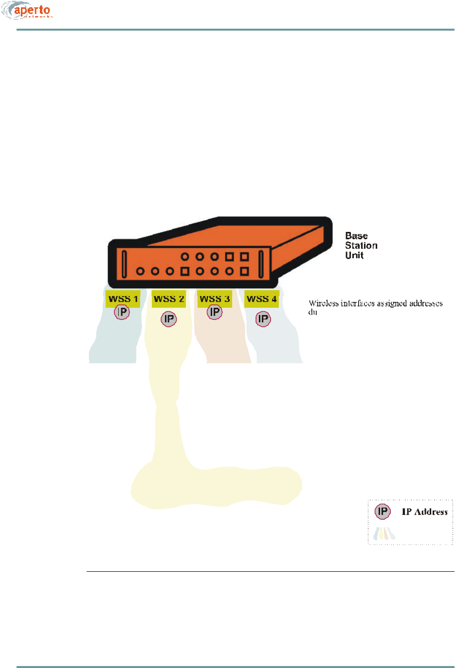
Figure2-7 shows multiple subnets on a wireless interface. Note that when a sub-
scriber Indoor Unit uses DHCP to request an address, neither the BSU (as DHCP relay
agent) nor the DHCP server can determine from the request which subnet the SU
should be assigned to. Therefore, IP and MAC addresses for all subscriber Indoor
Units on the wireless system must be manually entered into the DHCP server.
Figure2-7 Multiple Subnets on a WSS
2–15070-20000340-01 Rev A
CHAPTER 2. PACKETWAVE SYSTEM OVERVIEW
Variable-Length Subnets (VLSM)
The PacketWave System supports Variable-Length Subnet Masking (VLSM). The
essential characteristic of VLSM is that any number of contiguous final bits in an IP
address can define a subnet, meaning that subnets need not be limited to Class A, B,
or C sizes. Using VLSM addressing techniques (such as recursive subnetting) can
simplify routing and allow more efficient use of IP address space.
Figure2-8 shows an example of VLSM addressing in a PacketWave network. A full
discussion of VLSM is beyond the scope this manual, but detailed information can be
found in numerous books and online sources.
Figure2-8 VLSM on a PacketWave System

CHAPTER 2. PACKETWAVE SYSTEM OVERVIEW
2–16070-20000340-01 Rev A
Servers
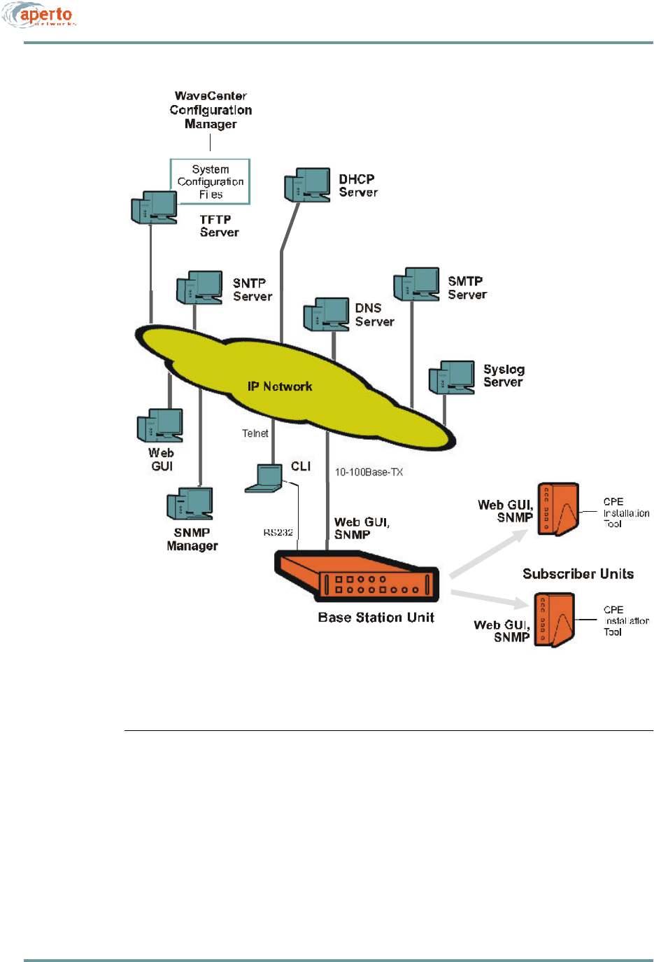
Each Base Station Unit requires access to DHCP and TFTP servers to boot up prop-
erly. Access to additional servers is required for the support of specific features.
For additional information about PacketWave System servers, including the configu-
ration of a DHCP server, see Chapter 7.
DHCP Server
The DHCP server assigns IP addresses to all of the PacketWave interfaces except the
Base Station Unit’s wireless interfaces. It also tells each Base Station Unit and sub-
scriber Indoor Unit the name of its configuration file, its default gateway, and the
addresses of other servers. Thus, the DHCP server is critical to the ability of
PacketWave Base Station Units and subscriber Indoor Units to communicate with the
rest of the Internet.
Because DHCP is based on a broadcast request from a client, and the Base
Station Unit is a DHCP client, the DHCP server or a DHCP relay agent must be
located on the same subnet as the Base Station Unit’s backhaul interface.
TFTP Server
For the PacketWave System, the main function of the TFTP server is to store the
system configuration files, and download them on request. Each Base Station Unit and
subscriber Indoor Unit requests its configuration file on hardware or software reboot
(cold or warm start).
Each Base Station Unit and subscriber Indoor Unit stores its configuration in
non-volatile memory. When it reboots, it downloads the latest configuration from
the TFTP server if it is able to, and then makes any changes to its configuration
based on a comparison of the downloaded configuration with the stored configu-
ration. If the device cannot successfully download its configuration from the
TFTP server, it operates with its stored configuration.
The TFTP server is also used to distribute software updates to Base Station Units and
subscriber Indoor Units as follows:
•The new software file is placed on the TFTP server.
•The configuration file for each unit to be downloaded is modified to specify the
new software, and then re-saved on the TFTP server.
•Each unit to be downloaded is rebooted. During reboot, a unit gets its new con-
figuration file, learns that a new software file is specified, and downloads the
software from the TFTP server.

2–17070-20000340-01 Rev A
CHAPTER 2. PACKETWAVE SYSTEM OVERVIEW
SNTP Server
The Base Station Unit typically derives the time and date from an SNTP (Simple
Network Time Protocol) server identified by the DHCP server. The BSU includes
time zone and daylight savings time parameters which it applies to the received time
and date as appropriate.
NOTE: Alternatively, date and time can be set via the Web and SNMP interfaces.
Subscriber Indoor Units use the BSU as their time server.
DNS Server
The DHCP server should identify an DNS server to be used in the resolution of
Internet domain names.
SMTP Server
The PacketWave Base Station Unit can use email to announce events. If this feature
is to be used, an SMTP (Simple Mail Transfer Protocol) server must be specified.
System Log Server (Syslog)
If a Syslog server is identified either by the DHCP server or in the BSU configuration,
the Base Station Unit will log all events to the specified server using the standard
Syslog protocol.
SNMP Manager
PacketWave Base Stations and subscriber Indoor Units include built-in SNMP (Sim-
ple Network Management Protocol) agents. These agents can be accessed by SNMP
managers as specified in the system configuration.
NOTE: PacketWave SNMP agents use SNMP v.2 syntax for objects.
CHAPTER 2. PACKETWAVE SYSTEM OVERVIEW
2–18070-20000340-01 Rev A
Figure2-9 PacketWave Servers and Management Access

2–19070-20000340-01 Rev A
CHAPTER 2. PACKETWAVE SYSTEM OVERVIEW
CONFIGURATION AND MANAGEMENT SOFTWARE
The PacketWave System includes the WaveCenter Configuration Manager for devel-
oping and maintaining the system’s configuration files. It also includes a browser-
accessible Web GUI interface and an SNMP interface for real-time monitoring and
management, plus a basic ASCII command line interface (CLI) for debugging/
troubleshooting.
Figure2-9 shows the PacketWave System’s management access.
Only configuration changes made using the WaveCenter Configuration Manager
affect the PacketWave System’s configuration data base. While some configura-
tion can be performed via the Web and SNMP interfaces, these changes are lost
if the configured equipment (Base Station or subscriber Indoor Unit) is rebooted.
WaveCenter Configuration Manager
The WaveCenter Configuration Manager (CM) is a Java-based application used to
configure PacketWave base station and subscriber equipment. It runs on any of the
following platforms:
•Windows 98
•Windows NT
•Windows 2000 Professional
•Linux
•Sun Solaris
NOTE: The platform on which the WaveCenter Configuration Manager is run must
include the Java Runtime Environment (JRE). JRE is included on the WaveCenter
distribution CD.
The Configuration Manager is used to create individual Base Station Unit and
subscriber configuration files. These files are then stored on the system’s TFTP
server, from which they are downloaded automatically by Base Station Units and sub-
scriber Indoor Units as part of their boot-up processes.
The PacketWave Configuration Manager has two parts: a Base Station Unit Config-
uration Manager and a Subscriber (CPE) Configuration Manager. Each consists of
multiple menus which in combination allow full configuration of the PacketWave
System components.
A complete description of the Configuration Manager and its use is given in Chapter
6 of this manual.

CHAPTER 2. PACKETWAVE SYSTEM OVERVIEW
2–20070-20000340-01 Rev A
Web-Based GUI
For real-time monitoring and limited configuration of the Base Station Unit and all of
its subscriber sites, the Base Station Unit supports a graphical user interface (GUI)
accessible via the IP network using a standard browser (currently, Netscape 4.74 or
Internet Explorer 5.0). The Web interface includes network views, performance
graphs, and event logs.
Details of the Web interface are given in Chapter 8 of this manual.
SNMP Agents
For real-time monitoring and limited configuration, each Base Station Unit and sub-
scriber Indoor Unit includes a built-in SNMP agent with trap support. (In R1P1, all
SNMP parameters are read-only).
More information about SNMP capability in Chapter 8 of this manual.
Command Line Interface
An ASCII command line interface (CLI) provides a compact set of commands which
are intended primarily for system troubleshooting by Aperto personnel or other
qualified technicians. The CLI can be accessed via Telnet or directly through the Base
Station Unit’s front-panel RS-232 port.
An overview of the CLI is given in Chapter 8 of this manual.

2–21070-20000340-01 Rev A
CHAPTER 2. PACKETWAVE SYSTEM OVERVIEW
SERVICE OFFERINGS AND QOS
The PacketWave System is designed to give service providers extreme freedom in the
definition of multiple services and the specification of quality-of-service (QoS) levels.
Before configuring individual subscribers, services and QoS parameters need to be
identified. Factors involved include:
•Service Class, which may be:
-Best Effort (BE)
-Committed Information Rate (CIR)
-Constant Bit Rate (CBR)
•Type of Service (TOS)
•Overall and peak bandwidths
Concepts of PacketWave Service Level Definition
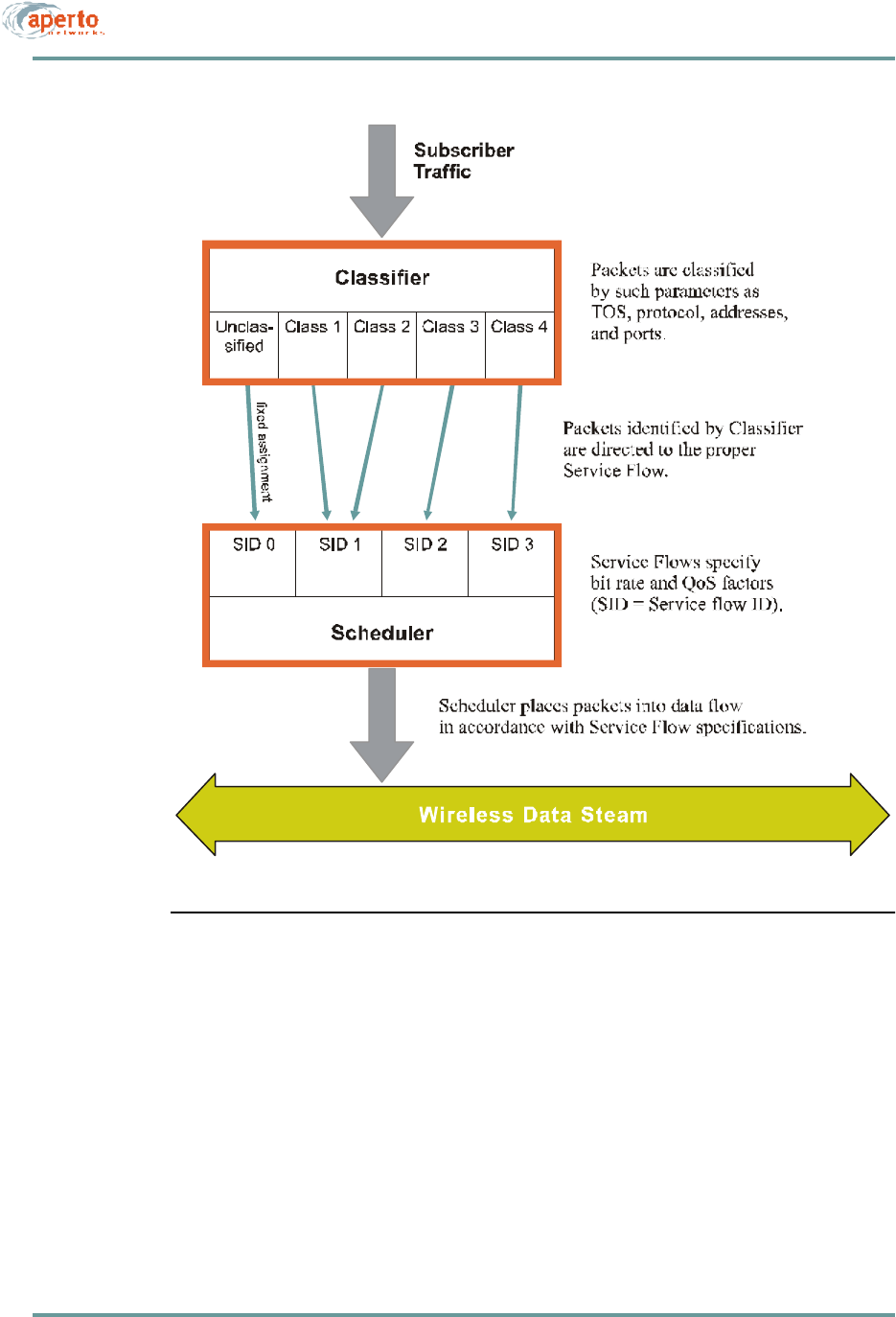
The PacketWave quality-of-service (QoS) capability is based on sets of classifiers and
service flows, and links between the two, as shown in Figure2-10.
•A classifier is one or more layer 2 and/or layer 3 parameters which will identify
a particular traffic flow.
•A service flow is a set of parameters which will determine the performance
characteristics (QoS) of traffic assigned to that flow.
When a classifier is defined, it is assigned to a specific service flow. Thus, any traffic
meeting the classifier specifications will be transmitted according to the performance
characteristics of its assigned service flow.
Assigning Service Levels
Service levels are assigned in the individual SU configuration files, allowing for max-
imum flexibility in differentiating service among subscribers.
Details of service level specification are provided in Chapter 6.
CHAPTER 2. PACKETWAVE SYSTEM OVERVIEW
2–22070-20000340-01 Rev A
Figure2-10 PacketWave Service Levels

3–1070-20000340-01 Rev A
3
SYSTEM PLANNING
This chapter summarizes issues related to the planning of a PacketWave System.
CELL SITE CONSIDERATIONS
The planning of a wireless cell site is a complex task requiring the knowledge and
skill of trained professionals. Location is of course a prime consideration, as are more
technical factors such as interference management and lightning protection. Aperto
expects that the cell site will be carefully thought out and professionally developed,
and that recognized procedures and codes will be faithfully observed.
When planning a cell site, take into account the following characteristics of the
PacketWave System:
•Base Station Location — While line-of-sight paths are not required between
PacketWave antennas at the base station and subscriber site, performance is
improved when transmission paths are unobstructed. Do whatever is practical
to minimize actual or potential transmission obstructions.
•Antenna and Radio Issues — PacketWave base station antennas and radios
are typically mounted on an antenna mast or tower, and include mounting
brackets for attachment to tubular structures (pipes). If a mounting structure
already exists, you will need to determine its suitability to the physical and
radio characteristics of the PacketWave components. If no mounting structure
exists or the existing one is not suitable, you will need to determine what type
of mounting structure is appropriate, then obtain and install the structure. You
will also need to determine the method by which antennas and radio will be
mounted to the structure, and obtain appropriate hardware if the standard hard-
ware included with the PacketWave components is not appropriate.

CHAPTER 3. SYSTEM PLANNING
3–2070-20000340-01 Rev A
•Base Station Enclosure — The PacketWave Base Station Units must be
located indoors, generally within 50 meters (165 feet) of the outdoor radios and
antennas. (Greater cable lengths require insertion of dc from an external
source.) Ensure that an adequate room or closet is available, that it meets the
Base Station Unit environment specifications, and that sufficient power (120 or
220 V ac, or -48 V dc) is available.
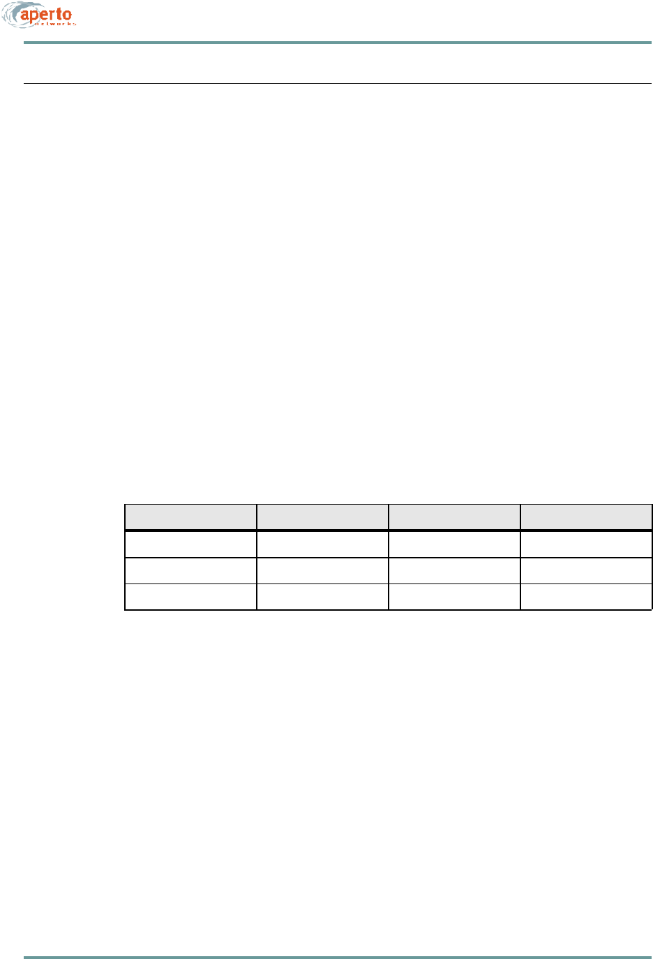
•Capacity and Equipment Requirements — PacketWave System capacity—
cell radius, sector and subscriber bandwidth, number of sectors, and number of
subscribers per sector—is discussed in Chapter 2 and summarized in Table3-A.
Use this information along with expected subscriber requirements to plan cell
size, sectors, and base station equipment.
•Radio Frequency Band — Determine the frequency band in which the system
will operate, and be sure that any required licences have been obtained. Make
sure that all PacketWave radio receivers and antennas you order are for the
proper frequency band.
Table3-A PacketWave System Capacities
Parameter Capacity
Cell radius Up to 5 miles (8 km) with line-of-site transmission paths and typical configura-
tion, or 1 mile (1.6 km) with obstructed paths. Where even wider coverage is
needed, the system can be configured to cover a radius of up to approximately
30 miles (50,000 m).
Sectors per BSU 1 to 6.
Sector width 60° or 90°.
Subscribers per sector Typically up to 250.
Total bandwidth 20 Mbps per sector; 120 Mbps per BSU.
Maximum bandwidth per sub-
scriber Individually configured; from 384 kbps to 10 Mbps.
Bursts to 20 Mbps.
Upstream-to-downstream
bandwidth ratio From 90% downstream and 10% upstream, to 90% upstream and 10% down-
stream. streamTj108 0 TD5.1643 Tystem

3–3070-20000340-01 Rev A
CHAPTER 3. SYSTEM PLANNING
CHAPTER 3. SYSTEM PLANNING
3–4070-20000340-01 Rev A
SUBSCRIBER SITE CONSIDERATIONS
Locations of subscriber sites are determined by the subscribers, within the limits of
the wireless cell. When implementing a subscriber site, consider the following:
•Subscriber Indoor Unit — Make sure the model chosen matches the sub-
scriber’s requirements for bridging/routing and host capacity.
•Radio Frequency Band — Make sure the PacketWave radio/antenna unit
operates in the wireless cell’s frequency band.
•Cabling — You will need to supply cables for connecting the subscriber Indoor
Unit to the outdoor radio/antenna, and for connecting the subscriber Indoor
Unit to the subscriber’s computer or LAN. Table3-C identifies the cables that
you will need to supply. (Cabling instructions are included in the PacketWave
100 Series Subscriber Equipment Installation and Operation manual.)
More complete planning instructions for the subscriber site are included in the
PacketWave 100 Series Subscriber Equipment Installation and Operation manual.
Table3-C Subscriber Site Cable Requirements
Connection — Qty Cable Type Max. Length Connectors
Ethernet (1) Cat 5 330 ft (100 m) RJ45 male
Radio Signal (1) Coaxial, quad shield 165 ft (50 m) Male F type
Radio Control (1) Cat 5, ourdoor rated 165 ft (50 m) RJ45 male

3–5070-20000340-01 Rev A
CHAPTER 3. SYSTEM PLANNING
IP PLANNING: ADDRESSING AND SUBNETTING
When planning a PacketWave System, make sure you fully understand the system’s
IP networking principles and requirements as discussed in Chapter 2.
Plan the network carefully; then document the various subnets and the individual IP
addresses. A topological diagram, while not required, will provide the most readily
understandable network documentation.
Make sure that the network plan includes the following:
•Base Station Unit’s MAC address (needed for DHCP configuration).
•Subnet and IP address for the Base Station Unit’s backhaul interface.
•Default gateway for the Base Station Unit’s backhaul interface.
•Servers accessible by the Base Station Unit.
•Wireless subnets, and IP addresses for the Base Station Unit’s WSS interfaces.
•MAC addresses of individual subscriber Indoor Units, matched to subscriber
site (needed for DHCP configuration).
•IP address for each subscriber Indoor Unit’s wireless interface.
•Default gateways for subscriber Indoor Units (Base Station Unit WSS inter-
faces).
•Subscriber LAN subnets and IP addresses, as appropriate.
Instructions for configuring a DHCP server with the above information are provided
in Chapter 7.
CONFIGURATION PLANNING
Each Base Station Unit and subscriber requires a separate configuration file which
must be generated using the WaveCenter Configuration Manager. For basic operation,
very simple configurations will suffice; the parameters which must be specified are:
•Base Station Unit — MAC address; WSS interface IP addresses and subnet
masks; wireless channel center frequencies.
•Subscriber Indoor Unit — MAC address; mode (bridge, router, or NAT);
model number.
However, there are numerous other parameters which can be specified to aid in net-
work administration, to add features, or to adjust performance. Details are provided
in Chapter 6 of this manual.

CHAPTER 3. SYSTEM PLANNING
3–6070-20000340-01 Rev A
Determine the amount of configuration appropriate for your network, and the specific
options to be selected. Document the configuration requirements for all Base Station
Units and subscribers.
Service Level Planning
Management of multiple service level offerings requires careful thought and signifi-
cant expertise in quality of service (QoS) issues and techniques. To maximize the flex-
ibility with which service levels can be defined and managed, the PacketWave System
includes extensive configuration options related to the establishment of specific types
and levels of service.
If multiple service levels are to be offered, they must be defined in the Subscriber Unit
(CPE) configuration files. Principles of service level definition and implementation
are discussed in Chapter 2; configuration details are presented in Chapter 6.

4–1070-20000340-01 Rev A
4
INSTALLING BASE STATION UNITS
The Base Station Unit (BSU) is a rack-mountable control unit that links up to six
radios and their antennas to the core network through a WAN backhaul channel. It
must be mounted indoors, protected from precipitation and temperature extremes.
CAUTION: Make sure that the room in which Base Station Units are installed
has temperature and humidity controls necessary to maintain the
temperature between 32 and 104 °F (0 and 40 °C) and the humid-
ity between 10% and 90% noncondensing.
MOUNTING
The Base Station Unit occupies two vertical rack units (3.5 inches) in a standard
19-inch equipment rack. It includes integral mounting ears as part of the front panel,
handles on the front panel near the mounting ears, and drawer slides on the sides of
the unit. Air flow holes are located on the sides of the enclosure, with a pair of cooling
fans on the rear panel.
CAUTION: Make sure that the equipment is mounted so that adequate air
flow around the BSU—particularly near the ventilation holes and
fans—is not blocked.
Secure the front panel to the equipment rack using the appropriate hardware.
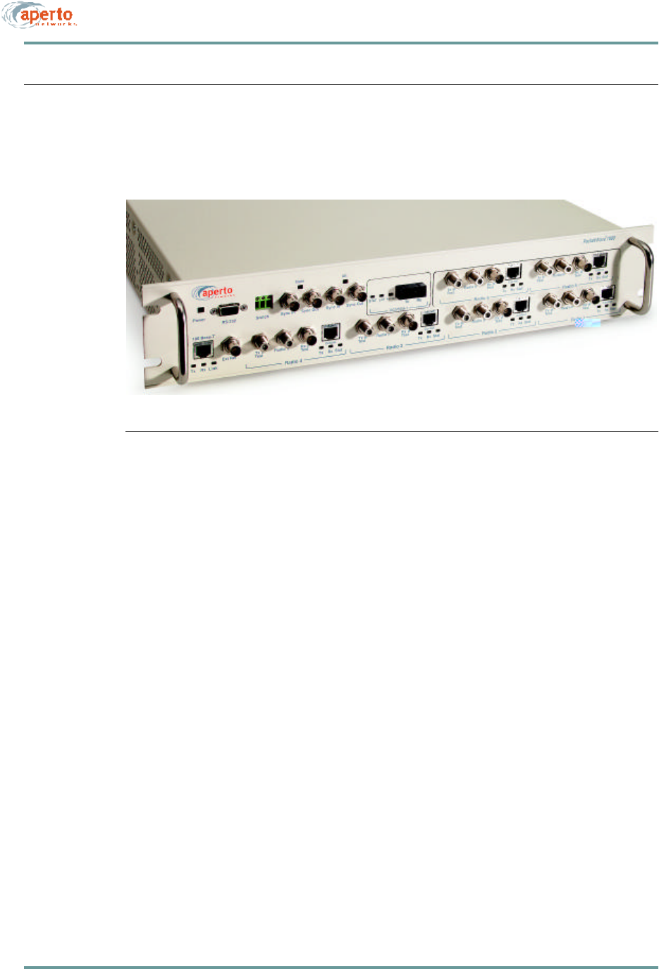
CHAPTER 4. INSTALLING BASE STATION UNITS
4–2070-20000340-01 Rev A
FRONT-PANEL CONNECTIONS
Other than the power connection, all connections to the Base Station Unit are made
on the front panel, which is illustrated in Figure4-1.
Figure4-1 BSU Front Panel
Connecting the Radios to the BSU
Connections from the outdoor radios to the Base Station Unit are described in Chapter
5 of this manual.
Connecting the Backhaul Link
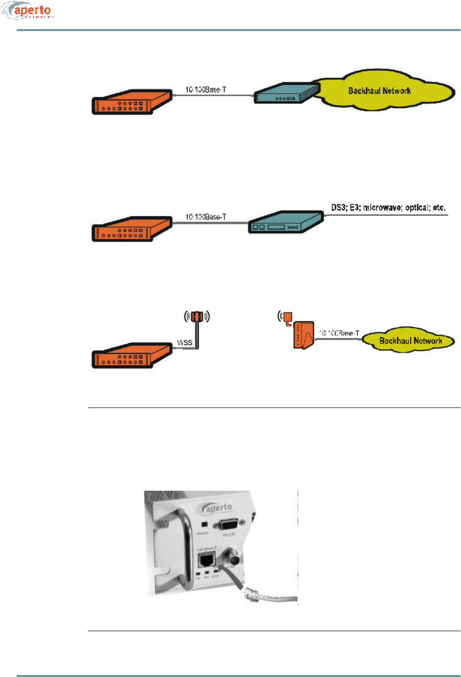
The standard backhaul connection for the Base Station Unit is a 10/100-BaseTX link.
This can be used for a range of different backhaul implementations, as shown in
Figure4-2.
To make the backhaul connection:
•Obtain or construct a Cat 5 cable of the required length, with a standard RJ45
plug on the BSU end and the appropriate connector on the other end.
•Insert one end of the cable with an RJ45 plug into the RJ45 socket labeled
100Base-T on the BSU front panel, as shown in Figure4-3.
•Connect the other end as appropriate for the particular backhaul implementa-
tion.
4–3070-20000340-01 Rev A
CHAPTER 4. INSTALLING BASE STATION UNITS
Figure4-2 Backhaul Channel Examples
Figure4-3 Backhaul Link Connection
To Ethernet backhaul router

CHAPTER 4. INSTALLING BASE STATION UNITS
4–4070-20000340-01 Rev A
Interconnecting Multiple BSUs at a Site
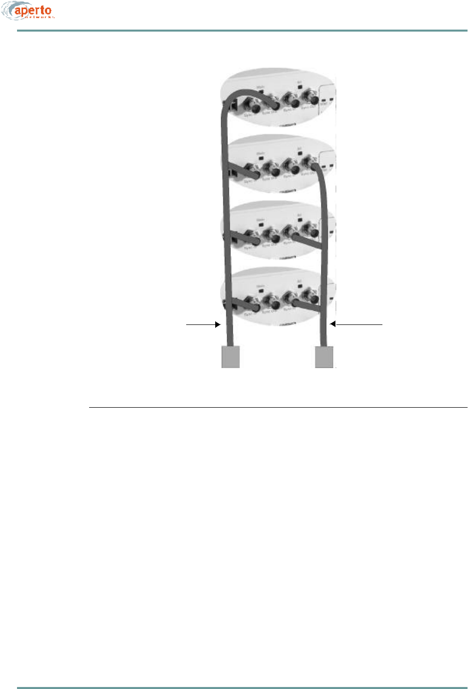
To properly identify wireless channel time slots, multiple colocated Base Station
Units need to be synchronized to the same framing signal. This is done by intercon-
necting the units’ Sync connectors, as shown in Figure4-4. When there are three or
more Base Station Units, a main and alternate sync signal source for the framing sig-
nal should be chosen; with two Base Station Units, no alternate is necessary.
Any Base Station Unit can be the source of a framing signal. If it is not receiving a
framing signal at one of its Sync In ports, a BSU will transmit a framing signal through
its Sync Out ports. Thus, when the primary framing signal source fails, the alternate
signal source can take over immediately.
To interconnect the multiple Base Stations:
1. Determine the Base Stations which will be the main and alternate sync signal
sources.
2. For the main sync signal, construct a coaxial cable with a BNC connector at
one end, a BNC T-connector for each Base Station Unit other than the main
sync source, and a 50-ohm terminator at the other end.
3. For the alternate signal source, construct a coaxial cable with a BNC connector
at one end, a BNC T-connector for each Base Station Unit other than the main
and alternate sync sources, and a 50-ohm terminator at the other end.
4. Connect the Main Sync Out connector on the main sync signal source to the Main
Sync In connectors on all other Base Station Units, as shown in Figure4-4.
5. Connect the Alt Sync Out connector on the alternate sync signal source to the
Alt Sync In connectors on all other Base Station Units except the main sync
signal source, as shown in Figure4-4.
4–5070-20000340-01 Rev A
CHAPTER 4. INSTALLING BASE STATION UNITS
Figure4-4 Sync Connections for Multiple BSUs
Connects Alt Sync Out
on Alternate Master
to Alt Sync In on all
BSUs except Master
Connects Main Sync Out
on Main Master
to Main Sync In on
all BSUs
50-ohm terminations
T connector
T connector
T connector
T connector
Coaxial Cable with
BNC Connectors
Coaxial Cable with
BNC Connectors
Alternate Sync Master
Main Sync Master
CHAPTER 4. INSTALLING BASE STATION UNITS
4–6070-20000340-01 Rev A
Connecting an External Reference Clock
For timing, a Base Station Unit can use its own internal oscillator, or a 10 MHz signal
from an external source. When multiple BSUs are colocated, it is a good idea to use
an external source to facilitate synchronization.
To connect an external source:
1. If it is not already present, install the reference source per the manufacturer’s
instructions.
2. Construct a coaxial cable with a the required connector for the reference source
at one end, a BNC T-connector for each BSU, and a 50-ohm termination at the
other end.
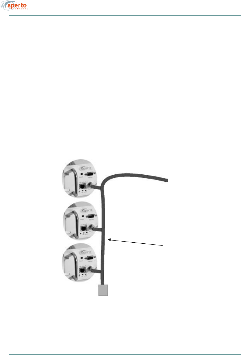
3. Connect the cable to the reference source and to the Ext Ref connector on each
BSU, as shown in Figure4-5.
Figure4-5 Connecting an External Reference Clock
Coaxial Cable with
BNC Connectors
10 MHz Reference
T connector
T connector
T connector
Connects Ext Ref
on all BSUs to
10 MHz reference clock
50-ohm termination
4–7070-20000340-01 Rev A
CHAPTER 4. INSTALLING BASE STATION UNITS
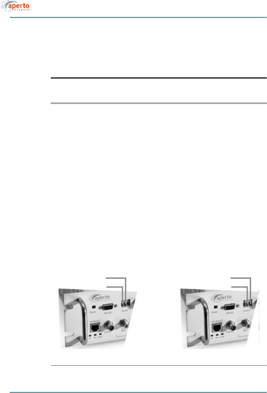
Connecting to the Alarm/Control Relay Switch
The Relay Switch connector on the Base Station Unit provides dry relay contacts for
operating external equipment. It supports normally-open and normally-closed circuits,
as shown in Figure4-6.
CAUTION: The alarm/control circuit connected to the relay switch should
present a maximum current of 2 A at 30 V dc. It may be either
normally open or normally closed.
To connect to the alarm/control switch relay:
1. Design and implement the desired external alarm or control circuit.
2. Use between 28 and 14 AWG wire (2.5 mm maximum diameter) for connection
to the BSU. Wire may be solid, stranded, or stranded with ferrule.
3. Verify whether the alarm/control circuit is normally closed or normally open.
4. For a normally-closed circuit, connect the leads to terminals 1 and 2. For a
normally-open circuit, connect the leads to terminals 2 and 3. Make the
connections by:
a. Loosening the screws above the wire holes, if necessary.
b. Inserting the wires into the proper holes.
c. Tightening the screws above the wire holes until the wires are held
securely.
Figure4-6 Connecting to the Relay Switch
Connections for
Normally-Open Circuit
Connections for
Normally-Closed Circuit
Common
Common
N.C.
N.O.
CHAPTER 4. INSTALLING BASE STATION UNITS
4–8070-20000340-01 Rev A
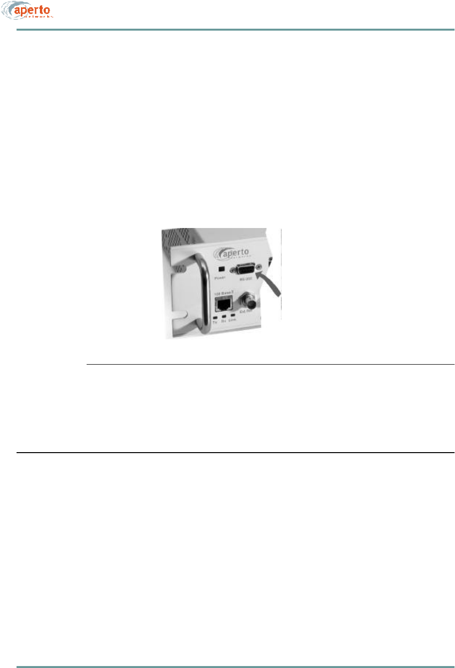
Connecting to the RS-232 Craft Port
The RS-232 craft port on the Base Station Unit supports a direct serial connection to
a PC, and is intended for temporary management and troubleshooting sessions using
a command line interface (CLI). The port employs a DB-9 female connector and oper-
ates with the following parameters: 38.4K baud, 8 bits, 1 stop bit, no parity.
To use the CLI through the craft port, connect the computer to the BSU front panel
as shown in Figure4-7, using a null-modem (crossover) cable up to 25 feet in length.
Operation of the CLI, which can also be accessed via Telnet, is discussed in Chapter
8 of this manual.
Figure4-7 Connecting to the RS-232 Craft Port
CONNECTING POWER
The Base Station Unit may come with either an ac or dc power supply. There is no
on-off switch on either model, so disconnecting the power cable or wires is the stan-
dard way to remove power from the BSU.
Generally, it is a good idea to make power connections after all other connections
have been made. However, any front-panel BSU connection can be disconnected and
reconnected while power is on.
To local computer
(command line interface only)
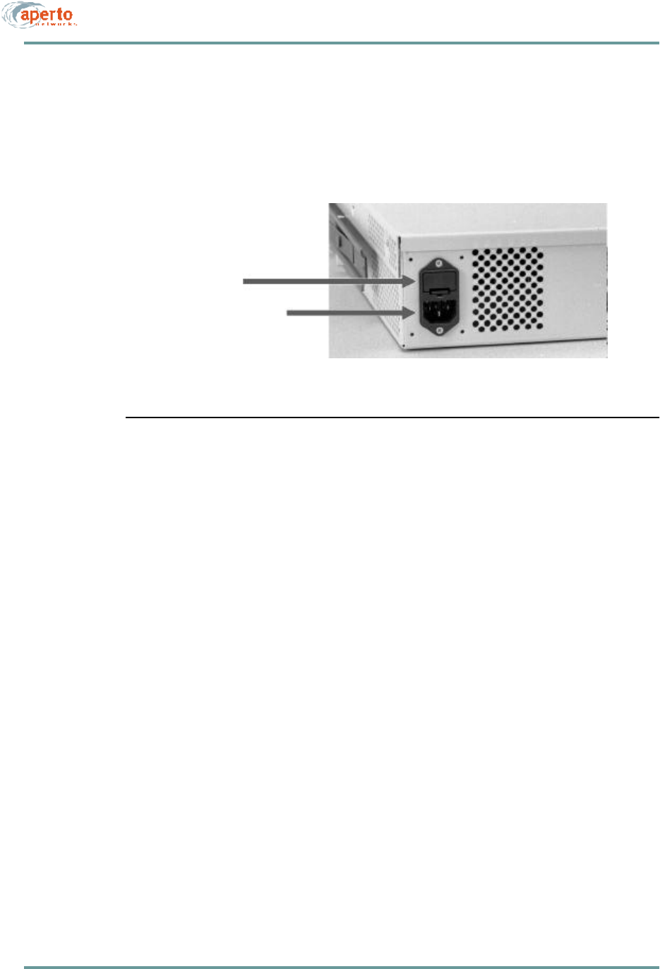
4–9070-20000340-01 Rev A
CHAPTER 4. INSTALLING BASE STATION UNITS
AC Power
An ac power cord is supplied with the Base Station Unit. To apply power to the BSU,
simply plug the cord into the receptacle on the rear panel of the BSU (shown in
Figure4-8) and then into a standard grounded wall outlet.
Figure4-8 AC Power Connection and Fuse Holder
Fuse
The ac power supply is protected by a fuse in a holder next to the power connector
on the rear panel of the Base Station Unit, as illustrated in Figure4-8. For the US and
other 120VAC power, the fuse is a 4 A, 250 V time-lag high-breaking fuse, 5 x 20
mm, such as the Schurter SPT 0001.2510.
Should this fuse blow, determine and correct the cause (if possible). Then replace the
fuse as follows:
1. Disconnect the BSU’s power cord.
2. Use a flat-bladed screwdriver to lever up the tab at the bottom of the fuse-
holder and remove the fuse holder.
3. Remove the fuse from the clips that hold it, and verify that the fuse has blown.
4. Place a new fuse in the clips.
5. Snap the fuse holder into the opening in the rear panel.
6. Reconnect the BSU’s power cord.
Fuse holder
ac cable connector
Rear of BSU, left corner

CHAPTER 4. INSTALLING BASE STATION UNITS
4–10070-20000340-01 Rev A
DC Power
The dc-power PacketWave 1000 includes dual terminal barrier connectors for redun-
dant -48 V dc power connections, plus two 4mm ground studs at the bottom edge of
the rear panel. You can connect to one or two power sources, as desired.
To connect to a dc power supply:
1. Use 12 AWG wire of no longer than 25 feet (8 m) for all power and ground
connections. On the BSU end of each power and ground wire, install a crimp-
style ring lug of 0.3 inches (7.5 mm) or less in diameter to fit between the ter-
minal barriers. Make sure the wires are marked or color-coded to identify pos-
itive and negative connections.
2. Install a connecting wire from one of the GND lugs to a good earth ground.
3. Connect the positive (+) and negative (-) terminals of one of the BSU’s dc
power connectors to a -48 V dc power source, using a Phillips screwdriver to
tighten the terminal posts on the ring lugs. Repeat for the other dc power con-
nector and power source, if desired.
4. If a redundant power supply is to be employed, repeat steps 3 and 4 for the
other power source, terminal block, and ground lug.

5–1070-20000340-01 Rev A
5
INSTALLING RADIOS AND ANTENNAS
The PacketWave base station antennas and radios are designed for mounting outdoors
on common antenna masts, and include mounting brackets for such mounting. Differ-
ent mounting hardware can be substituted as appropriate for your antenna support.
INSTALLING THE ANTENNA MOUNTING SYSTEM
Various antenna mounting systems can be used for the PacketWave base station.
Choose a mounting system appropriate for your particular network and site, and fol-
low the manufacturer’s directions to install.
If the antenna mounting system has a directional aspect (for example, a six-sided
antenna mast), be sure to consider the physical sector locations when installing.
CAUTION: Be sure that the antenna mounting system is appropriate for the
weights and wind-resistance of all of the antennas and radios to
be installed on it, and for local environmental conditions.
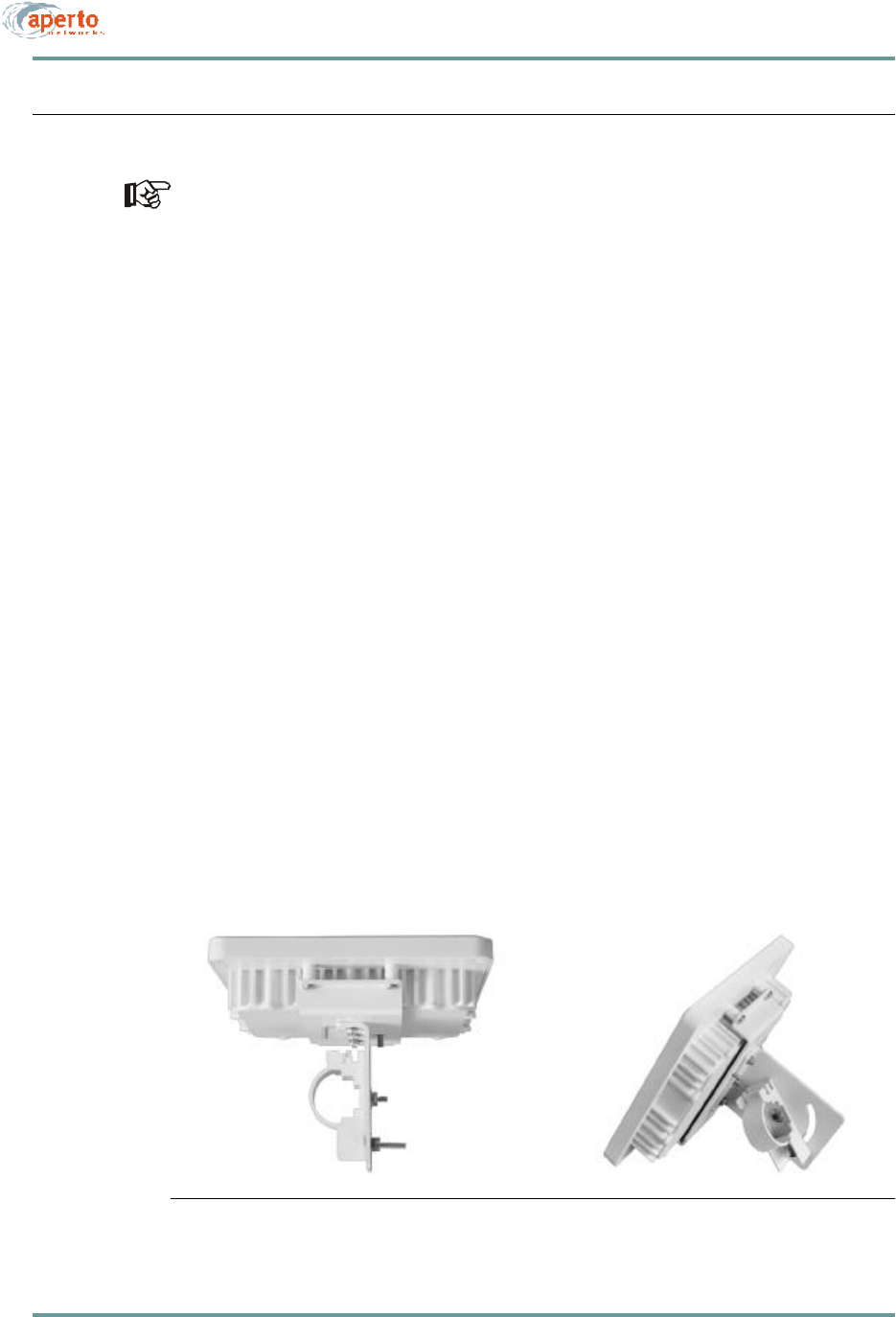
CHAPTER 5. INSTALLING RAD IOS AN D ANTENN AS
5–2070-20000340-01 Rev A
MOUNTING THE ANTENNAS AND RADIOS
Before mounting the antennas, you need to know the compass directions and ele-
vation tilts appropriate for each sector. (The antennas have a beam width of 60°
or 90° horizontal and 9° vertical).
There are several antennas which may be used in a PacketWave system. Because of
their different sizes and weights, the antennas do not all use the same mounting acces-
sories.
The base station radio includes a rear-mounted bracket as shown in Figure5-1; the
bracket accomodates a pole diameter of 1.5 inches (3.8 cm), 2 inches (5 cm)
To mount an antenna:
1. Determine the mounting location for the antenna.
2. Orient the antenna vertically.
3. Using the mounting equipment provided, or other mounting hardware as
desired, secure the antenna to the mast or other support.
To mount a radio:
1. Determine the exact location for the radio.
2. Loosen the pole clamp bolt and open the pole clamp.
3. Orient the radio so that the F and RJ45 connectors are at the bottom.
4. Close the pole clamp around the pole.
5. Adjust the direction and elevation of the radio/antenna unit.
6. Tighten the pole clamp bolt until the radio/antenna unit is secured in position.
Figure5-1 Base Station Radio Mounting Bracket

5–3070-20000340-01 Rev A
CHAPTER 5. INSTALLING RADIOS AND ANTENNAS
RUNNING THE RADIO CABLES
Connections to the radio include two “RF jumper” connections “up” to the antenna
and two connections “down” to the Base Station Unit.
Radio to Antenna
The radio is connected to the antenna by two cables. One end of each is attached to
the radio internally, and the other terminates with a male N connector, as shown in
Figure5-2.
To connect the radio to the antenna:
1. Connect the cables from the radio to the appropriate connectors on the antenna.
2. Apply a silicone sealant or other weatherproofing to the connections as desired.
Radio to Base Station
There are two cables that connect each radio to its Base Station Unit: a radio signal
cable (which also carries dc power) and a control cable. These cables run from out-
door radios to the indoor BSU, so a suitable cable run and building entry point must
be identified, as discussed in Chapter 3. Connections to the BSU are illustrated in
Figure5-3; Connections to the radio are illustrated in Figure5-4.
For these outdoor-to-indoor connections, the order of the steps in the installation
procedure will vary depending on a number of factors, including site particulars
and installers’ preferred practice. For example, in some cases it may be best to
run unterminated cable and then attach connectors; in others it may be more effi-
cient to attach one or both connectors to the cable before running it. Also, cable
dressing at various locations may be best performed at different points in the pro-
cedure. Therefore, the procedures given for radio-to-BSU connections should be
taken as a list of necessary steps and a suggested order, and modified as appro-
priate for your particular circumstances.
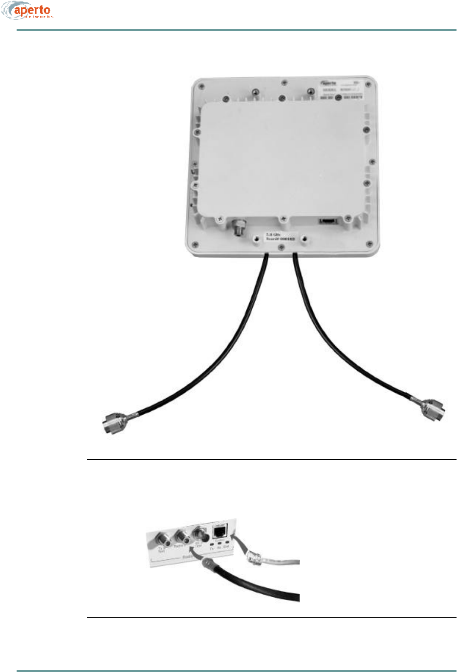
CHAPTER 5. INSTALLING RAD IOS AN D ANTENN AS
5–4070-20000340-01 Rev A
Figure5-2 Radio Cables for Connection to Antenna
Figure5-3 BSU Radio Connections
Control cable to radio
Signal cable to radio
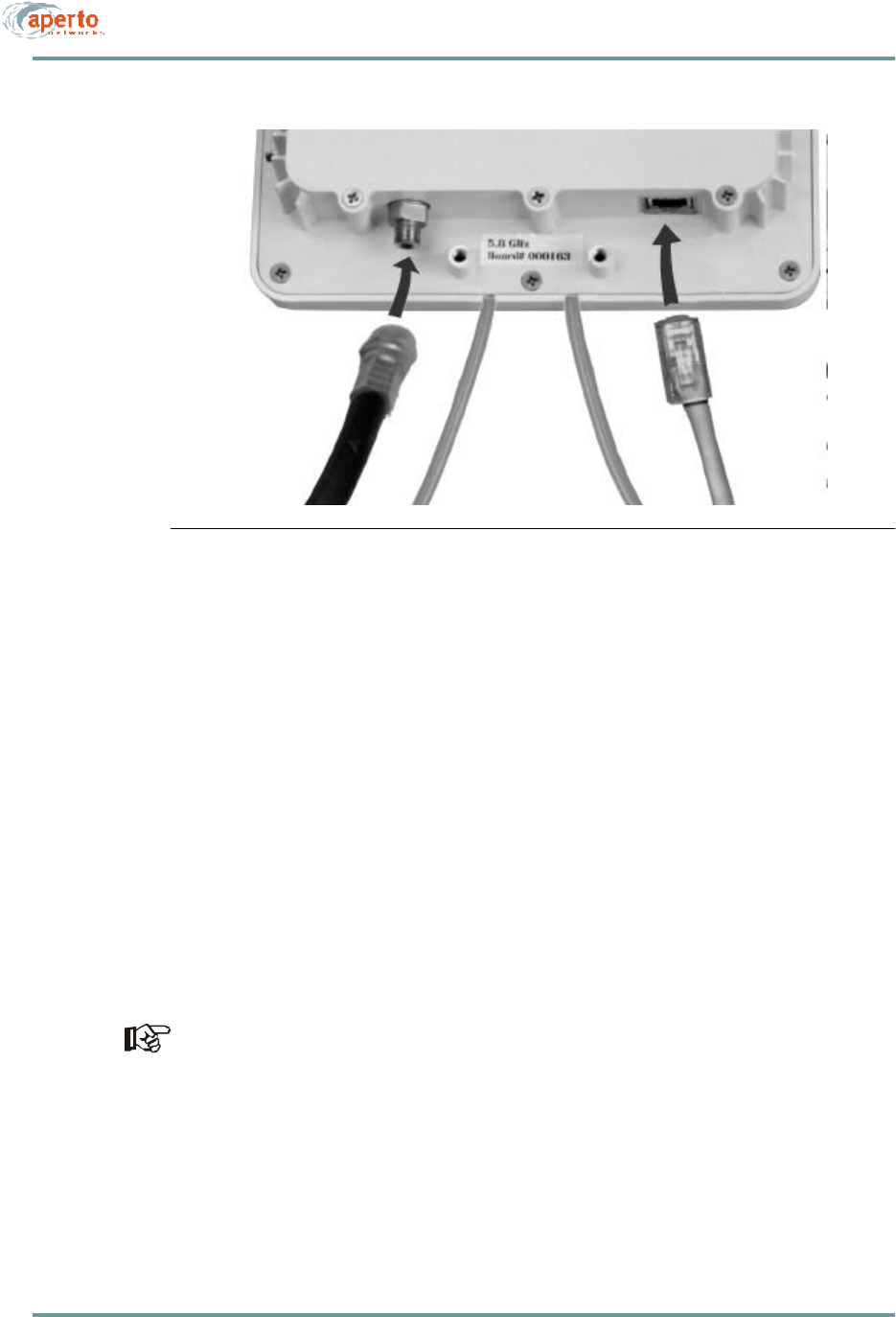
5–5070-20000340-01 Rev A
CHAPTER 5. INSTALLING RADIOS AND ANTENNAS
Figure5-4 Radio Signal and Control Connections
Radio Signal Connection
The radio signal cable should be outdoor-rated 75-ohm quad-shield coaxial cable with
a maximum length of 165 feet (50 m) unless dc voltage is inserted from an external
source. The cable terminates with a male F connector at each end.
To install the radio signal cable, perform the following steps:
1. Run an appropriate length of cable from the BSU to the radio. Include a service/
drip loop as appropriate.
2. Install a male F connector at the radio end of the cable.
3. Attach the cable to the female F connector on the radio, as shown in Figure5-4.
4. Dress the outdoor portion of the cable as appropriate.
5. Install a male F connector on the BSU end of the cable.
If the cable is longer than 165 feet, replace step 7 with the steps in the section
headed DC Voltage Insertion for Extra-Long Cables later in this chapter.
6. Attach the cable to the Radio IF connector for the appropriate Radio port on the
Base Station Unit, as shown in Figure5-3.
7. Dress the indoor portion of the cable as appropriate.
Control cabl
Signal cable
to BSU
to BSU

CHAPTER 5. INSTALLING RAD IOS AN D ANTENN AS
5–6070-20000340-01 Rev A
Control Connection
The radio signal cable should be shielded outdoor-rated Cat 5, and may be up to 165
feet (50 m) in length. It terminates with an RJ45 male connector at each end.
To install the radio control cable, perform the following steps:
1. Obtain an appropriate length of cable, and run it from the BSU to the radio.
Include a service/drip loop as appropriate.
2. Place the supplied rubber boot over the radio end of the cable.
3. Install an RJ45 male connector on the radio end of the cable.
4. Plug the cable into the RJ45 socket on the radio, as illustrated in Figure5-4.
5. Put the rubber boot in position to protect the RJ45 connection and secure it in
place with a cable tie. Make sure the longer side of the rectangular boot is par-
allel to the top lid of the rado.
6. Dress the outdoor portion of the cable as appropriate.
7. Install an RJ45 male connector on the BSU end of the cable.
8. Plug the cable into the Control connector for the appropriate Radio port on the
Base Station Unit, as shown in Figure5-3.
9. Dress the indoor portion of the cable as appropriate.
10. Seal the entry of the radio signal and control cables to the building as appropriate.
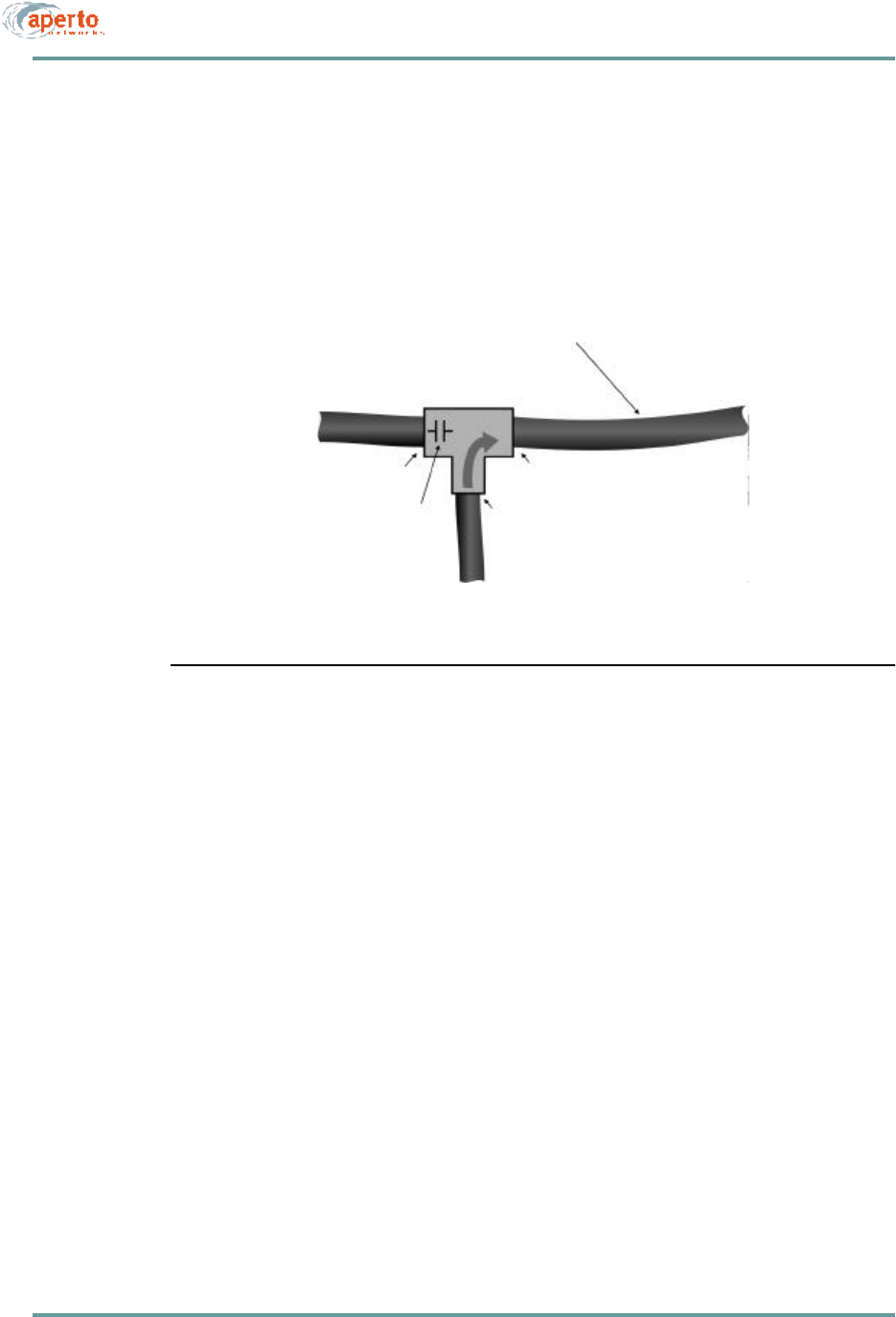
5–7070-20000340-01 Rev A
CHAPTER 5. INSTALLING RADIOS AND ANTENNAS
DC Voltage Insertion for Extra-Long Cables
If the radio signal cable is longer than 165 feet (50 meters), the power provided by
the Base Station Unit via this cable will be attenuated to the point that it is insufficient
to properly power the radio. In such a case, power must be inserted onto the radio
signal cable using a bias tee and an external power source (18 V dc, 1.5 A) as illus-
trated in Figure5-5.
Figure5-5 DC Power Insertion for Radio
To insert dc voltage onto the radio signal cable:
1. Provide an 18 V dc power source capable of supplying 1.5 A, a coaxial bias tee
with two female F connectors and one BNC connector, and a short coaxial
cable with a male F connector at each end.
2. Connect the short coaxial cable to the RADIO IF connector on the Base Station
Unit as illustrated in Figure 5-4.
3. Connect the other end of the short coaxial cable to the dc blocking side (female
F connector) of the bias tee as shown in Figure 5-5.
4. Connect the radio signal cable from the outdoor unit to the other female F con-
nector on the bias tee as shown in Figure 5-5.
5. Connect a cable from the 18 V dc power source to the BNC connector of the
bias tee as shown in Figure 5-5.
Radio signal cable
Length greater than 50 ft (15 m)
Bias Tee
To BSU To Radio
18 V dc source, 1.5 A
F connectorsF connectors
BNC connectors
dc block

CHAPTER 5. INSTALLING RAD IOS AN D ANTENN AS
5–8070-20000340-01 Rev A

6–1070-20000340-01 Rev A
6
BSU AND SUBSCRIBER
CONFIGURATION
This chapter describes how to use Aperto’s WaveCenter Configuration Manager™ to
configure the base station and subscriber equipment in a PacketWave System.
Creating the BSU and subscriber (CPE) configuration files and placing them on the
TFTP server is half of the PacketWave system configuration. The other half is the
configuration of the IP network, including the DHCP server, described in Chapter 7.
INSTALLING THE WAVECENTER CONFIGURATION MANAGER
The WaveCenter Configuration Manager is provided on CD as part of the BSU pack-
age. You can load the WaveCenter Configuration Manager onto a computer running
any of the following operating systems:
•Windows 98
•Windows NT
•Windows 2000 Professional
•Linux
•Sun Solaris
Whatever the platform, it will need to have the Java Runtime Environment (JRE)
installed on it. If the JRE is not already present, it can be installed from the Wave-
Center CD.

CHAPTER 6. BSU AND S UBSCRIBER CONFIGURATION
6–2070-20000340-01 Rev A
Depending on the particulars of your network, it may be a good idea to run the
WaveCenter Configuration Manager on the same computer that provides the system’s
TFTP server. If you run the Configuration Manager on a different computer, you must
be able to move the files created by the Configuration Manager to the TFTP server
computer.
To install the WaveCenter Configuration Manager:
1. Place the CD in the CD-ROM drive and view the contents. Note that there is a
cm folder/directory, which contains the Configuration Manager installation
files, and a jre folder/directory, which contains the executable file for the Java
Runtime Environment.
2. If the computer does not already have the Java Runtime Environment installed,
open the jre folder/directory and run the executable file (jre<version>.exe).
3. Open the cm folder/directory; then open the appropriate folder/subdirectory for
your platform and run the appropriate setup file. For example, for a Windows
system open the win32 folder and run setup.exe.
4. Follow the prompts in the installation wizard.
5. When installation has been completed, a WaveCenter Configuration Manager
icon will have been placed on the desktop. Double-click this icon to launch the
WaveCenter Configuration Manager.
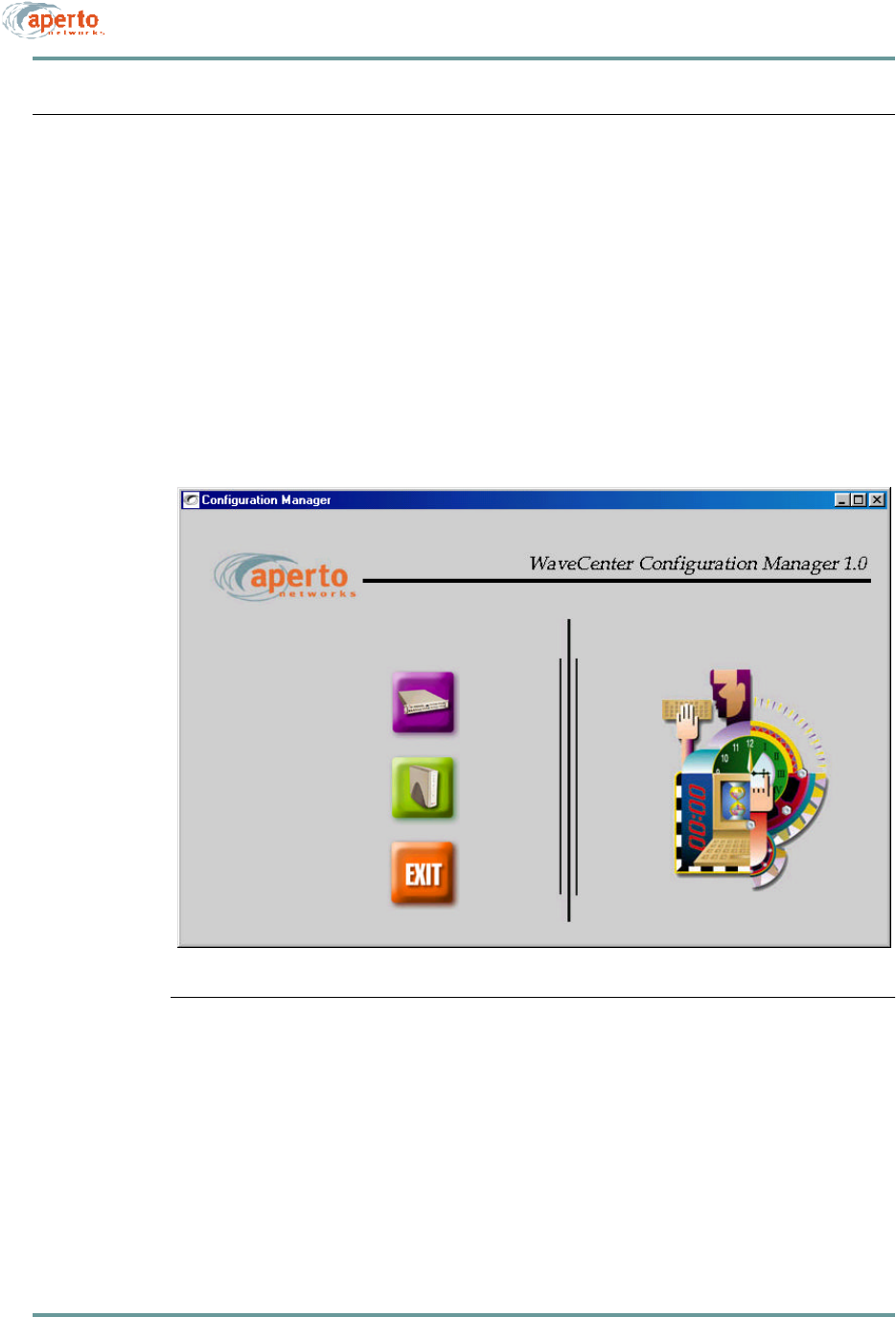
6–3070-20000340-01 Rev A
CHAPTER 6. BSU AND S UBSCRIBER CONFIGURATION
HOW THE WAVECENTER CONFIGURATION MANAGER WORKS
The WaveCenter Configuration Manager is used to create a separate configuration file
for each Base Station Unit and each subscriber in the system. Each base station unit
and subscriber site (CPE) must have a valid configuration file in order to function.
BSU and Subscriber Branches
The WaveCenter Configuration Manager consists of separate Base Station Unit and
subscriber (CPE) branches, accessed by clicking the BSC and SU (CPE) icons shown
in Figure6-1. To configure a Base Station Unit, click on the BSC icon. To configure
subscriber equipment, click on the subscriber Indoor Unit (CPE) icon.
Figure6-1 WaveCenter Configuration Manager Home Screen
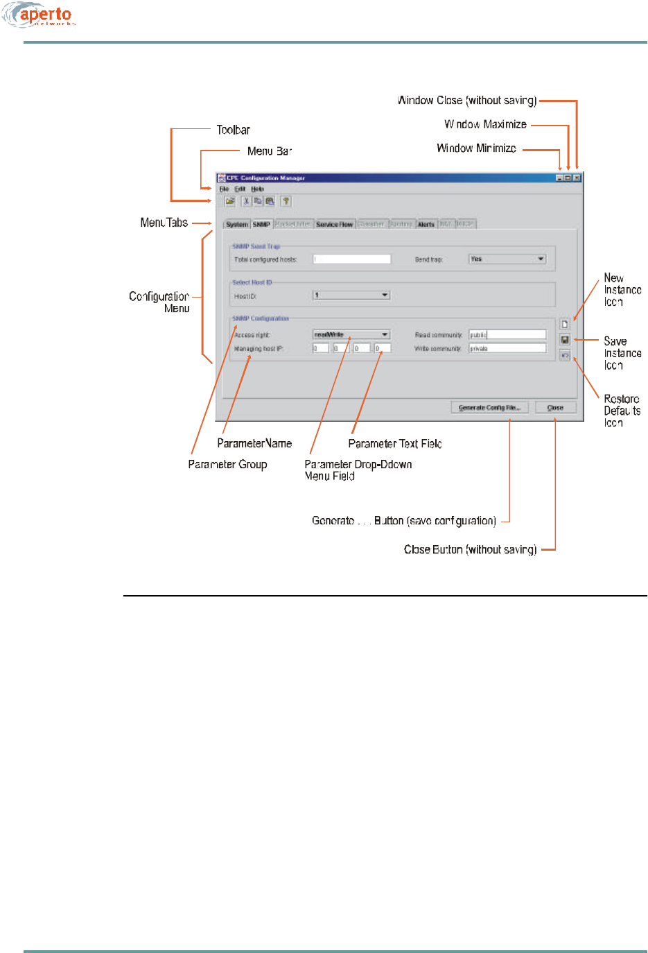
CHAPTER 6. BSU AND S UBSCRIBER CONFIGURATION
6–4070-20000340-01 Rev A
Figure6-2 WaveCenter Configuration Manager Screen Elements
Configuration Screen Formats
Each branch of the WaveCenter Configuration Manager (BSU and subscriber/CPE)
consists of multiple configuration menu screens identified and accessed by tabs.
Figure6-2 shows a typical screen and its elements, while Table6-A defines the ele-
ments.
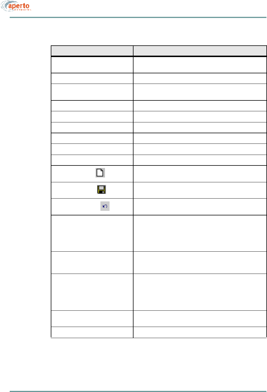
6–5070-20000340-01 Rev A
CHAPTER 6. BSU AND S UBSCRIBER CONFIGURATION
Table6-A Functions of CM Screen Elements
Screen Element Function
Menu Bar: File Allows opening and saving of configuration files, and exiting from
(i.e., closing) the CM branch.
Menu Bar: Help Opens CM help files (future).
Toolbar Provides one-click access to open, cut, copy, paste, and help (same
as corresponding Menu Bar functions).
Menu Tabs Allow navigation among the various configuration pages.
Configuration Menu Includes all configuration parameters for the tab.
Parameter Group Description for a group of related parameters.
Parameter Name Descriptive name for a single configurable item.
Parameter Text Field Area where you configure a parameter by entering text.
Parameter Drop-Down Menu Field Area where you configure a parameter be choosing from a menu.
New Instance Icon Used to open a new instance of the element being configured in this
menu—for example, an additional SNMP manager.
Save Instance Icon Used to save a particular instance as configured on this menu—
for example, an SNMP manager.
Restore Defaults Icon Used to restore factory defaults for the parameters on the page.
Generate BSC Config button Used to create/save the BSU configuration file with parameters as
currently specified on all pages.
Similar to File — Save As menu option, except the Generate
BSC Config button causes the CM to suggest a default file name
of bsc_<MACaddress>.cfg.
Generate WSS Config button Used to save a particular WSS configuration as part of the current
BSU configuration. A WSS configuration file is created on disk as
part of the process but need not be copied to the TFTP server.
Generate Configuration File
button Used to create/save the subscriber (CPE) configuration file with
parameters as currently specified on all pages.
Similar to File — Save As menu option, except the Generate
Configuration File button causes the CM to suggest a default
file name of cpe_<MACaddress>.cfg.
Close Button Closes the CM branch window without saving the file (same as
File — Exit menu option).
Window Close, Maximize, Minimize The standard window controls.