Aperto Networks R3000-A1 WLAN Base Station and Subscriber Unit User Manual PacketWave 1000 Manual Rev A July 2001
Aperto Networks WLAN Base Station and Subscriber Unit PacketWave 1000 Manual Rev A July 2001
Contents
- 1. Subscriber user manual
- 2. Base Station user manual 1 of 2
- 3. Base Station user manual 2 of 2
Base Station user manual 2 of 2

CHAPTER 6. BSU AND S UBSCRIBER CONFIGURATION
6–6070-20000340-01 Rev A
Managing Configuration Files
Before using the WaveCenter Configuration Manager, be sure you understand the
principles of configuration file management discussed below.
Opening and Loading Files
When you click on the BSU or subscriber Indoor Unit (CPE) icon on the WaveCenter
Configuration Manager home screen, a new (“blank”) configuration file is opened
with the default parameters. You can then load an existing file by selecting File —
Open from the menu bar, or the file open icon on the toolbar. The Configuration Man-
ager will let you browse for the desired file.
NOTE: Some screens have a new instance icon on the right side. This icon does not
cause a new configuration file to be opened; rather, it causes a new instance to be
opened, and is displayed only on pages which can be configured multiple times for
multiple instances (such as multiple SNMP managers; see Figure6-2).
Saving Files
There are two methods for saving configuration files, as identified in Table6-A:
•Selecting File — Save as from the page menu line. The Configuration Manager
will prompt for a file name.
•Clicking on the Generate BSC Config or Generate Configuration File (CPE)
button. The Configuration Manager will prompt with the suggested file name
in the format bsc_<MACaddress>.cfg or cpe_<MACaddress>.cfg, using the
MAC address entered during configuration. See the discussion of file names
below.
NOTE: Some screens have a page save icon on the right side. This icon does not
cause the configuration file to be saved; rather, it causes the current instance to be
added to the configuration file which is being created or modified. The page save
icon is displayed only on pages which can be configured multiple times for multiple
instances (such as multiple SNMP managers; see Figure6-2).
File Names
Configuration files are required to have unique names so that each BSU and sub-
scriber Indoor Unit can download the correct configuration file from the TFTP server.
Table6-B identifies the naming convention suggested by Aperto, which uses MAC
addresses to guarantee uniqueness. These are the default names used when you click
on the Generate BSC Config or Generate Configuration File button, as described above.
While the naming convention identified in Table6-B is recommended, it is not
required. You can use any other format you wish, as long as the names are unique.

6–7070-20000340-01 Rev A
CHAPTER 6. BSU AND S UBSCRIBER CONFIGURATION
Storage Location
To be accessed by the Base Station Units and subscriber Indoor Units when they boot,
the configuration files must be specified in the DHCP server’s configuration file and
stored in the default directory (typically, \tftpboot) of the TFTP server. You can save
directly to that directory when creating the configuration files, or save to a different
location and then transfer the files before booting the configured units.
Configuration Template Files
It will often be efficient to create generic configuration files which can be used as
templates when adding new BSUs, WSSs, or subscribers.
You create and save a configuration template the same way you create and save a con-
figuration file, but save it with a descriptive file name rather than a file name linking
it by MAC address to a specific unit. Then, when you want to use the template as the
basis for a new configuration file, you load the template, make any changes necessary,
and save the file using the correct file name for the new unit.
NOTE: Similarly, you can base a new configuration file on an existing configuration
file by loading the existing file, editing it, and saving it using the proper file name
for the new unit.
Downloading Configuration Files
After the configuration files have been created and stored on the TFTP server, the con-
figured devices need to be booted up. (The Base Station Unit must be operational
when a subscriber Indoor Unit is initialized, or the initialization will fail.) The booted
device will then automatically download its configuration from the TFTP server.
Each Base Station Unit and subscriber Indoor Unit stores its configuration in
non-volatile memory. When it reboots, it downloads the latest configuration from
the TFTP server if it is able to, and then makes any changes to its configuration
based on a comparison of the downloaded configuration with the stored configu-
ration. If the device cannot successfully download its configuration from the
TFTP server, it operates with its stored configuration.
Table6-B Suggested Convention for Naming Configuration Files
Configured Entity File Name Format Example
Base Station Unit bsc_<MACaddress>.cfg bsc_00013b0002e4.cfg
(for MAC 00:01:3b:00:02:e4)
Subscriber cpe_<MACaddress>.cfg cpe_00013b00025d.cfg
(for MAC 00:01:3b:00:02:5d)

CHAPTER 6. BSU AND S UBSCRIBER CONFIGURATION
6–8070-20000340-01 Rev A
USING THE WAVECENTER CONFIGURATION MANAGER
To configure a cell using the WaveCenter Configuration Manager, follow this general
procedure:
1. Launch the WaveCenter Configuration Manager by clicking on the desktop
icon. The program’s home screen will be displayed, as shown in Figure6-1.
2. Click on the BSU icon. A BSU Configuration Manager window will open.
3. Configure the Base Station Unit as described later in this chapter, under the
heading Base Station Configuration.
NOTE: If there are multiple BSUs, you may want to create and use a template file.
See the section Managing Configuration Files earlier in this chapter.
4. When you are done, click on the Generate BSC Config button to save the BSU
configuration.
5. Close the BSU Configuration Manager window. If there is another BSU to con-
figure, return to step 2. If there is no other BSU to configure, go to step 6.
6. Click on the home page’s subscriber Indoor Unit (CPE) icon. A subscriber CPE
Configuration Manager window will open.
7. Configure the subscriber equipment as described in the section Subscriber
Equipment Configuration later in this chapter.
NOTE: You may want to create and use a template file. See the section Managing
Configuration Files earlier in this chapter.
8. When you are done, click on the Generate Configuration File button to save
the subscriber configuration.
9. Close the CPE Configuration Manager window. If there is another subscriber
to configure, return to step 6. If there is no other subscriber to configure, go to
step 10.
10. Exit from the WaveCenter Configuration Manager.
11. Copy all of the configuration files to the default directory for the system’s
TFTP server, typically \tftpboot (unless you saved them directly to that
directory).
6–9070-20000340-01 Rev A
CHAPTER 6. BSU AND S UBSCRIBER CONFIGURATION
BASE STATION CONFIGURATION
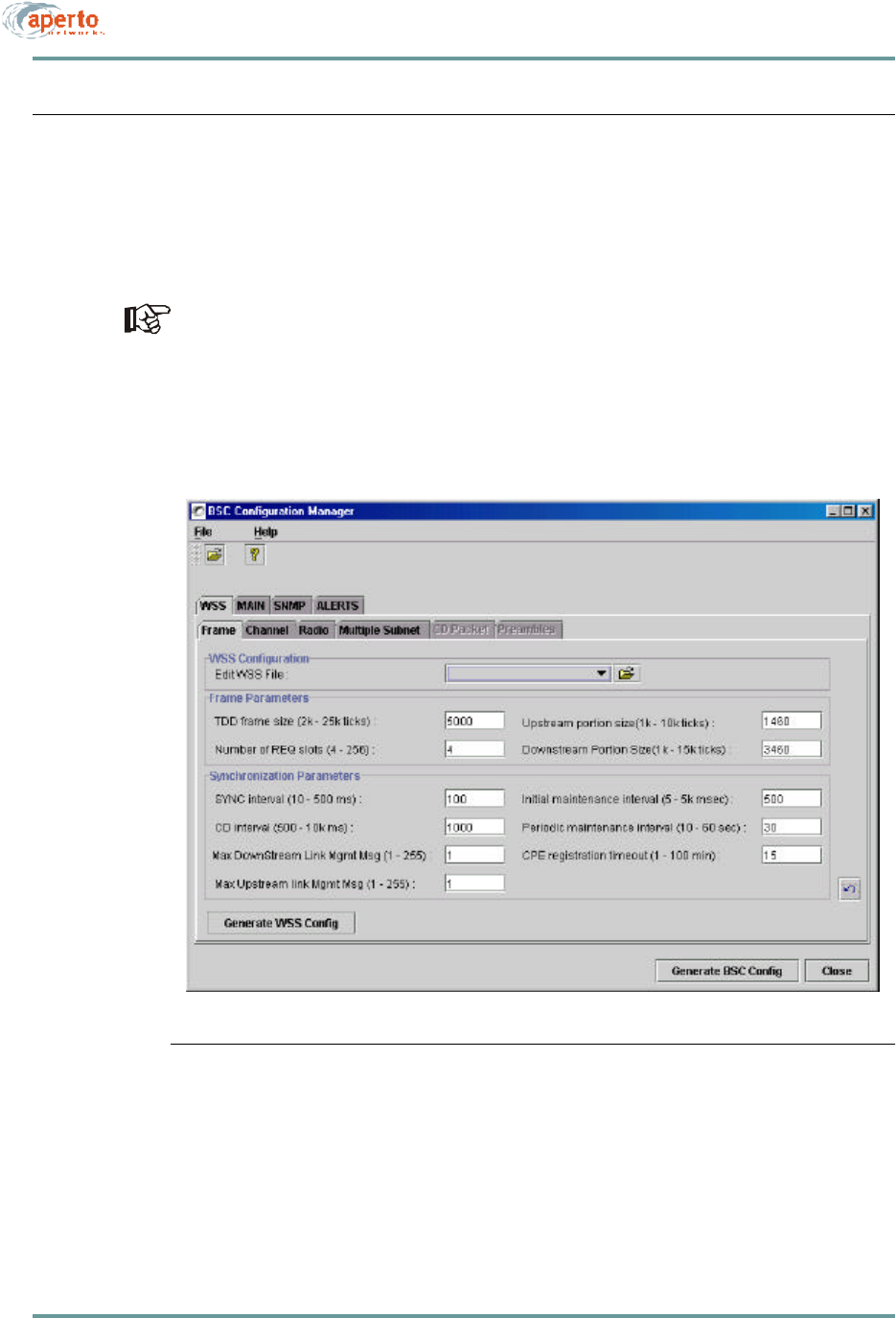
To configure a Base Station Unit, including the wireless radio interfaces (WSSs, or
wireless subsystems), click on the BSU icon on the WaveCenter Configuration Man-
ager home screen (Figure6-1). The BSU Configuration Manager will open in a new
window, as shown in Figure6-3.
There are four required parameters for WSS/BSU configuration: WSS center fre-
quency (WSS — Frame menu); WSS subnet IP addresses and subnet masks
(WSS — Multiple Subnet menu); and BSU MAC address (MAIN — General
menu. All other parameters are optional.
Figure6-3 Base Station Opening Menu (WSS — Frame)

CHAPTER 6. BSU AND S UBSCRIBER CONFIGURATION
6–10070-20000340-01 Rev A
There are four first-level menu tabs for BSU configuration, as shown by the upper
row of tabs in Figure6-3:
•WSS — Used to configure each wireless subsystem (radio interface) on the
Base Station Unit.
•Main — Used to specify various parameters for the Base Station Unit itself.
•SNMP — Used to configure the Base Station Unit for SNMP management.
•Alerts — Used to configure the Base Station Unit for email event alerts.
Configuring Wireless Subsystems (WSS)
Click on the WSS tab in the upper row. As the second row of tabs in Figure6-3
shows, there are six menus for configuring a WSS:
•Frame — Used to specify how the wireless signal will be framed and synchro-
nized.
•Channel — Used to configure the wireless communication channel.
•Radio — Used to configure the radio and antenna connected to the WSS.
•Multiple Subnet — Used to specify at least one subnet and mask per WSS.
•CD Packet —
•Preamble —
The WSS Configuration — Edit WSS File: field on the Frame menu allows you
to load an existing WSS configuration file, causing all of the WSS menus to dis-
play the current settings for that WSS file. You can then either modify that file, or
save it under another name.
You will need to create a separate configuration for each WSS. The basic procedure
is as follows:
1. Start with the WSS — Frame menu (Figure6-3). If desired, use the Edit WSS
File field to load an existing WSS configuration as a template.
2. Complete the other WSS menus as described on the following pages.
3. Click on the Generate WSS Config button, and specify the WSS you are con-
figuring.
4. Repeat for all WSSs.

6–11070-20000340-01 Rev A
CHAPTER 6. BSU AND S UBSCRIBER CONFIGURATION
Frame Parameters
Click on the Frame tab so that the screen illustrated in Figure6-3 is displayed.
Specify frame parameters as indicated in Table6-C.
Table6-C BSU — WSS — Frame Parameters
Parameter Range
(and Default) Comments
Edit WSS File file name (no default) If desired, click on the File Open icon at the right of
the field and then select a file to use as a template
for the WSS to be configured.
TDD Frame Size 2000 to 25000 ticks
(5000) Advanced configuration parameter; change only if
directed by Aperto Networks.
Number of REQ Slots 4 to 256 slots
(4) Advanced configuration parameter; change only if
directed by Aperto Networks.
Upstream Portion Size 1000 to 10000 ticks
(1460) Adjust these parameters to alter the ratio of
upstream to downstream bandwidth. Reduce the
value of one by the amount you add to the amount
of the other so the total remains the same (up +
down = frame size - guardband).
Downstream Portion Size 1000 to 15000 ticks
(3460)
SYNC Interval 10 to 500 ms
(100) Advanced configuration parameter; change only if
directed by Aperto Networks.
CD Interval 500 to 10000 ms
(1000) Advanced configuration parameter; change only if
directed by Aperto Networks.
Downstream Max Link
Mgmt Msg 1 to 255
(1) Advanced configuration parameter; change only if
directed by Aperto Networks.
Upstream Max Link Mgmt
Msg 1 to 255
(1) Advanced configuration parameter; change only if
directed by Aperto Networks.
Initial Maintenance Interval 5 to 5000 ms
(500) Advanced configuration parameter; change only if
directed by Aperto Networks.
Periodic Maintenance
Interval 10 to 60 seconds
(30) Advanced configuration parameter; change only if
directed by Aperto Networks.
CPE Registration Timeout 1 to 100 minutes
(15) Advanced configuration parameter; change only if
directed by Aperto Networks.
CHAPTER 6. BSU AND S UBSCRIBER CONFIGURATION
6–12070-20000340-01 Rev A
Channel Parameters
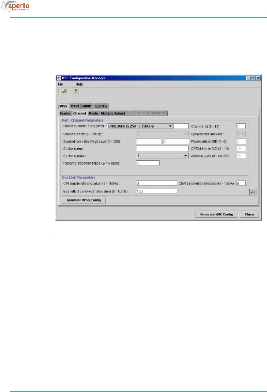
Click on the Channel tab so that the screen illustrated in Figure6-4 is displayed.
Specify channel parameters as indicated in Table6-D.
Figure6-4 WSS — Channel Menu

6–13070-20000340-01 Rev A
CHAPTER 6. BSU AND S UBSCRIBER CONFIGURATION
Table6-D BSU — WSS — Channel Parameters
Parameter Range
(and Default) Comments
Channel Center Freq (MHz) 9 menu options for
frequency range, plus
center frequency field
Select the frequency range from the drop-down
menu; then enter the channel center frequency to be
used in communication with all subscribers in the
sector.
Required field.
Symbol Rate Ratio range x to y : a to b
(1 : 1) Advanced configuration parameter; change only if
directed by Aperto Networks. Not supported in
R1P1.
Sector name (no default) Enter the name chosen for the sector served by this
WSS.
Sector Number 1 to 6
(1) Choose a number to identify the sector. Generally,
you should use the WSS port number.
Channel Width 1000 to 7000 kHz
(6000) Not supported in R1P1.
Channel ID 0 to 15
(1) Specify a channel identification number.
Symbol Rate Allowed 1 or 2
(1) Advanced configuration parameter; change only if
directed by Aperto Networks. Not supported in
R1P1.
Flow ID Bits in SID 1 to 6
(2) Advanced configuration parameter; change only if
directed by Aperto Networks. Not supported in
R1P1.
CPE ID Bits in SID 2 to 10
(10) Advanced configuration parameter; change only if
directed by Aperto Networks. Not supported in
R1P1.
Ranging Tx Power Steps 2 to 16 dBm,
(4) Specify the step size for transmit power ranging.
Antenna Gain 0 to 48 dBi(15) Not supported in R1P1.
CIR Bandwidth Allocation 0 to 100%
(0) Specify the percentage of the total bandwidth to be
devoted to each of the three service classes.
The three percentages should total exactly 100%.
They should also correlate to the total bandwidths
assigned to all subscribers in the sector, with appro-
priate oversubscription based on statistical multi-
plexing expectations.
CBR Bandwidth Allocation 0 to 100%
(0)
Best Effort Bandwidth
Allocation 1 to 100%
(100)

CHAPTER 6. BSU AND S UBSCRIBER CONFIGURATION
6–14070-20000340-01 Rev A
Radio Parameters
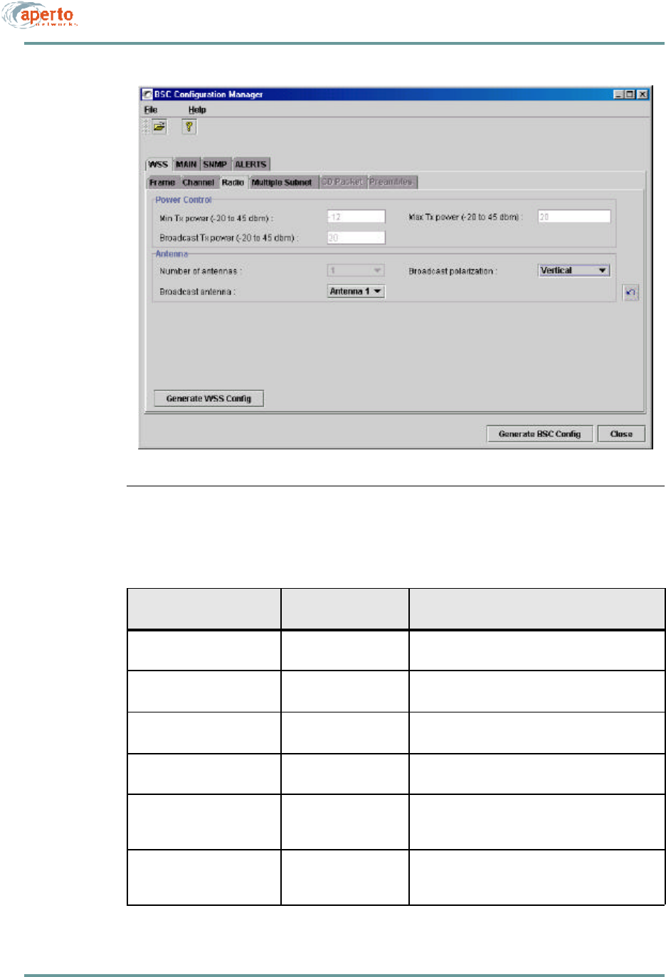
Click on the Radio tab so that the screen illustrated in Figure6-5 is displayed. Specify
radio parameters as indicated in Table6-E.
Multiple Subnet Parameters
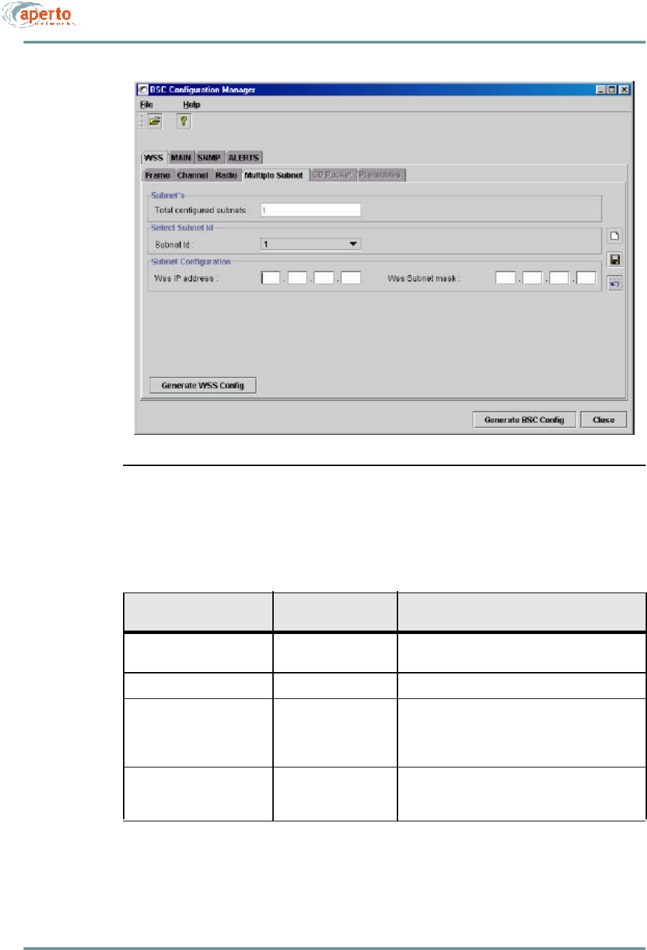
Click on the Multiple Subnet tab so that the screen illustrated in Figure6-6 is
displayed.
Specify the WSS IP address and subnet mask for the first (and typically only) subnet,
as indicated in Table6-F. Click on the save icon when you are finished.
You must specify at least one subnet and mask before generating the WSS config-
uration file.
If desired, create another subnet by clicking on the new instance icon. Specify the
WSS IP address and subnet mask for the new subnet. Click on the save icon when
you are finished.
Repeat for as many subnets as desired.
CD Packet Parameters
CD Packet parameters are not supported in R1P1.
Preamble Parameters
A configurable preamble is not supported in R1P1.
6–15070-20000340-01 Rev A
CHAPTER 6. BSU AND S UBSCRIBER CONFIGURATION
Figure6-5 WSS — Radio Menu
Table6-E BSU — WSS — Radio Parameters
Parameter Range
(and Default) Comments
Min Tx Power -20 to 4 dBm
(-12) Specify the minimum transmit power allowed in
power ranging. Not supported in R1P1.
Broadcast Tx Power -20 to 4 dBm
(20) Specify the transmit power used for broadcasts to all
subscribers. Not supported in R1P1.
Max Tx Power -20 to 4 dBm
(20) Specify the maximum transmit power allowed in
power ranging. Not supported in R1P1.
Number of Antennas 1 or 2
(1) Specify whether this sector uses 1 or 2 antennas.
Not supported in R1P1.
Broadcast Antenna Antenna 1 or 2
(1) If this sector uses 2 antennas, specify the antenna
to be used for broadcasts to all subscribers. Not
supported in R1P1.
Broadcast Polarization Horizontal, Vertical,
Horizontal & Vertical
(Vertical)
Specify the antenna polarization used for broad-
casts to all subscribers.
CHAPTER 6. BSU AND S UBSCRIBER CONFIGURATION
6–16070-20000340-01 Rev A
Figure6-6 WSS — Multiple Subnets Menu
Table6-F BSU — WSS — Multiple Subnet Parameters
Parameter Range
(and Default) Comments
Total Configured Subnets Read-only field; increments each time a new subnet
is added using the new instance icon.
Subnet ID Read-only field indicating subnet being configured.
WSS IP Address xxx.xxx.xxx.xxx
(no default) Enter the IP address for the WSS subnet. Typically
this will follow the standard gateway address con-
vention for subnets.
Required field (one instance).
WSS Subnet Mask xxx.xxx.xxx.xxx
(no default) Enter the subnet mask which defines the subnet
address range.
Required field (one instance).
6–17070-20000340-01 Rev A
CHAPTER 6. BSU AND S UBSCRIBER CONFIGURATION
Configuring the Main Base Station Parameters
Click on the MAIN tab in the upper row. As the second row of tabs shows, there are
three menus for configuring the main base station parameters:
•General — Used for cell, IP, and SNTP (time) configuration, and for specify-
ing the active wireless subsystems (WSS).
•Server IP — Used for specifying the IP addresses of the various servers
accessed by the Base Station.
•Bridging/Clustering — Used to create multi-sector clusters, and to enable or
disable bridging between subscribers in the same sector or cluster.
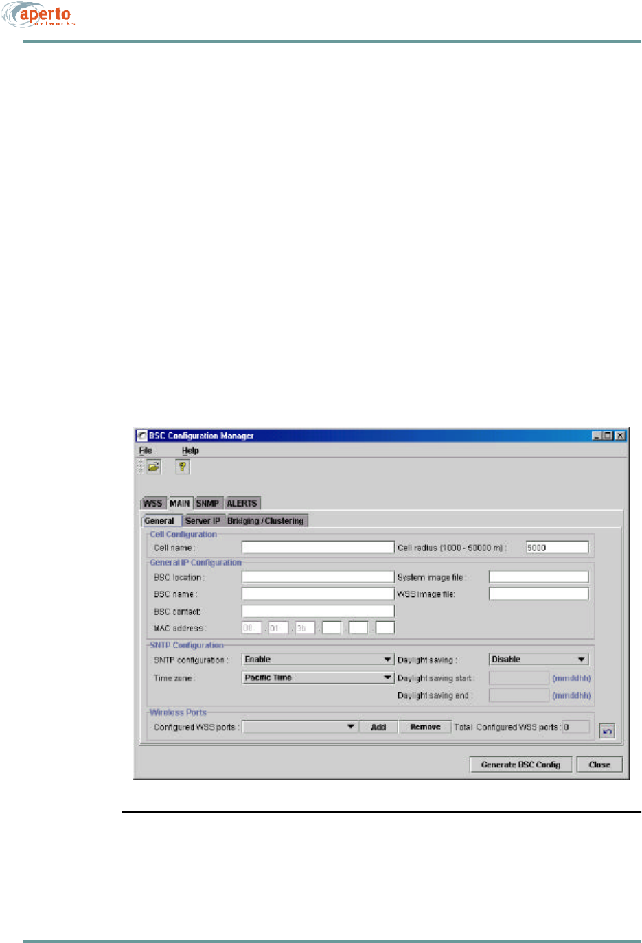
General Parameters
Click on the General tab so that the screen illustrated in Figure6-7 is displayed.
Specify parameters as indicated in Table6-G.
Figure6-7 MAIN — General Menu

CHAPTER 6. BSU AND S UBSCRIBER CONFIGURATION
6–18070-20000340-01 Rev A
Table6-G BSU — MAIN — General Parameters
Parameter Range
(and Default) Comments
Cell Name Up to 79 characters
(no default) Enter the name chosen for the cell served by the
BSU.
Cell Radius 1000 to 50000 meters
(5000)
BSU Location Up to 79 characters
(no default) Enter text identifying the location of the BSU.
BSU Name Up to 79 characters
(no default) Enter the name chosen for the BSU.
BSU Contact Up to 79 characters
(no default) Enter contact information regarding the BSU.
MAC Address 00:01:3b:xx:xx:xx
(no default) Complete the MAC address of the BSU as identified
by a label on the BSU. (All Aperto MAC addresses
begin with 00:01:3b.)
Required field.
System Image File file name Identifies the system software which should be run-
ning on the BSU. If different software is running, the
BSU will attempt to download the specified software
from the TFTP server.
WSS Image File file name Identifies the WSS software which should be run-
ning on the BSU. If different software is running, the
BSU will attempt to download the specified software
from the TFTP server.
SNTP Configuration Enable or Disable
(Enable)Specify whether the BSU will obtain date and time
from an SNTP server. (The SNTP server is specified
in the DHCP server configuration.)
Time Zone Drop-down menu of
time zones worldwide. Select the appropriate time zone from the drop-
down menu.
Daylight Saving Enable or Disable
(Disable)Specify whether daylight saving time will be
observed.
Daylight Saving Start mmddhh
(no default) Enter the date at which daylight savings time will
start.
Daylight Saving End mmddhh
(no default) Enter the date at which daylight savings time will
end
Configured WSS Ports (drop-down menu) Read-only field identifying the number of WSS ports
which have been configured (using WSS menu set
and Generate WSS Config button).
Total WSS Ports 0 to 6
(0)Specify the number of WSS ports to be configured.

6–19070-20000340-01 Rev A
CHAPTER 6. BSU AND S UBSCRIBER CONFIGURATION
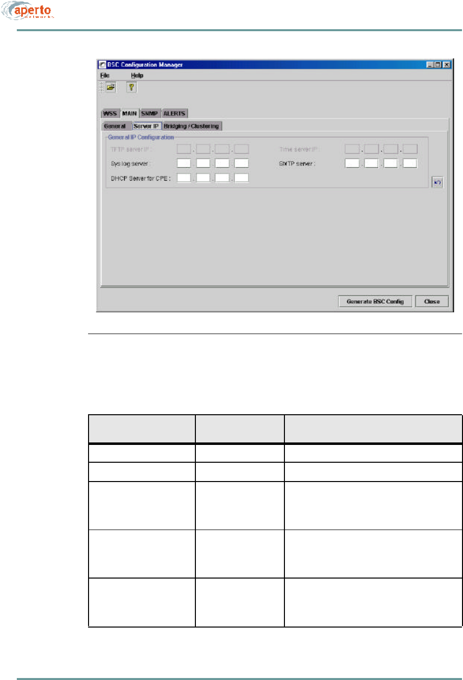
Server IP Parameters
Click on the Server IP tab so that the screen illustrated in Figure6-8 is displayed.
Three server IP addresses are configurable, as identified in Table6-H. Specify any
server IP addresses as desired.
Syslog and SMTP server identifications made on this menu will be overridden by
Syslog and SMTP server identifications made in the DHCP server configuration.
NOTE: TFTP and DHCP server addresses are not configurable; they are learned
from the DHCP server when the BSU boots up.
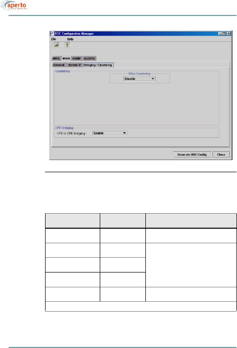
Bridging/Clustering Parameters
Click on the Bridging/Clustering tab so that the screen illustrated in Figure6-9 is
displayed. Specify bridging and clustering options as described in Table6-I.
Clustering allows two or more WSSs to be on the same subnet, which can provide
greater efficiency in the use of IP addresses. Subscriber-to-subscriber (CPE-to-
CPE) bridging makes communications between subscribers in the same subnet
more efficient.
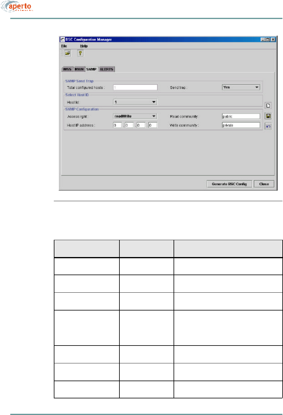
Configuring SNMP Parameters
Click on the SNMP tab in the upper row, so that the screen illustrated in Figure6-10
is displayed.
Specify parameters for Host 1, as indicated in Table6-J. Click on the save instance
icon when you are finished.
If desired, open a new Host by clicking on the open instance icon. Specify parameters
for the new host. Click on the save instance icon when you are finished. Repeat for
as many hosts as desired (to a maximum of 32).
CHAPTER 6. BSU AND S UBSCRIBER CONFIGURATION
6–20070-20000340-01 Rev A
Figure6-8 MAIN — Server IP Menu
Table6-H BSU — MAIN — Server IP Parameters
Parameter Range
(and Default) Comments
TFTP Server IP N/A Non-configurable field.
Time Server IP N/A Non-configurable field.
Syslog Server xxx.xxx.xxx.xxx decimal
(no default) If the BSU is to log event messages to a Syslog
server, enter its IP address. (If a Syslog server is
identified in the DHCP server, this address will be
overridden.)
SMTP Server xxx.xxx.xxx.xxx decimal
(no default) If the BSU is to send email alert messages, enter the
SMTP server’s IP address. (If an SMTP server is
identified in the DHCP server, this address will be
overridden.)
DHCP Server for CPE xxx.xxx.xxx.xxx decimal
(no default) If subscribers are to use a different DHCP server
than the BSU, specify the subscribers’ DHCP server
here. (This address will be the DHCP server known
by the BSU’s DHCP relay agent.)
6–21070-20000340-01 Rev A
CHAPTER 6. BSU AND S UBSCRIBER CONFIGURATION
Figure6-9 MAIN — Bridging/Clustering Menu
Table6-I BSU — MAIN — Bridging/Clustering Parameters
Parameter Range
(and Default) Comments
WSS Clustering Enable or Disable
(Disable) * Specify whether WSSs will be clustered. If Disable
is specified, the Cluster fields will be unavailable.
Cluster I Any 2 or more config-
ured WSS ports Select a configured WSS, and then click on the clus-
ter in which it will be included.
Cluster II Any 2 or more config-
ured WSS ports
Cluster III Any 2 or more config-
ured WSS ports
CPE-to-CPE Bridging Enable or Disable
(Enable) * Specify whether bridging between subscribers in the
same WSS/cluster will be enabled.
* If WSS Clustering is to be enabled, CPE-to-CPE Bridging must be enabled.
CHAPTER 6. BSU AND S UBSCRIBER CONFIGURATION
6–22070-20000340-01 Rev A
Figure6-10 SNMP Menu
Table6-J BSU — SNMP Parameters
Parameter Range
(and Default) Comments
Total Configured Hosts 1 to 32 Read-only field indicating how many SNMP hosts
have been specified.
Send Trap Yes or No
(Yes)Specify whether SNMP traps will be sent to trap-
enabled hosts (per Access Right configurations).
Host ID 1 to 32 (increments as
instances are opened) Identifies the SNMP host being configured.
Access Right readOnly, readWrite,
roWithTraps,
rwWithTraps,
trapsOnly
(readWrite)
Specify the access the SNMP host will have
Host IP Address xxx.xxx.xxx.xxx decimal
(0.0.0.0)Specify the IP address of the SNMP host.
Read Community Up to 79 characters
(public)Specify the name of the community which will have
read access to the BSU.
Write Community Up to 79 characters
(private) Specify the name of the community which will have
write access to the BSU.
6–23070-20000340-01 Rev A
CHAPTER 6. BSU AND S UBSCRIBER CONFIGURATION
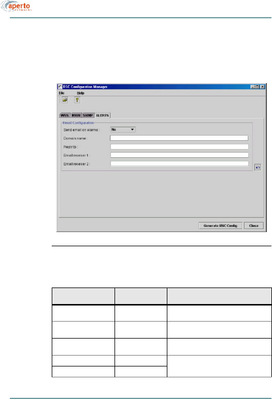
Configuring Email Alert Parameters
Click on the ALERT tab in the upper row, so that the screen illustrated in Figure6-11
is displayed. Specify email alert parameters as indicated in Table6-K.
Figure6-11 ALERT Menu
Table6-K BSU — ALERTS Parameters
Parameter Range
(and Default) Comments
Send Email on Alarms Yes or No
(No)Specify whether email alert message will be sent.
Domain Name Up to 63 characters
(no default) Specify the email domain name for the BSU.
Reply To Up to 63 characters
(no default) Enter the sending email address for alert messages.
Email Receiver 1 any email address Enter the email address(es) to which alert mes-
sages will be sent.
Email Receiver 2 any email address
CHAPTER 6. BSU AND S UBSCRIBER CONFIGURATION
6–24070-20000340-01 Rev A
SUBSCRIBER CONFIGURATION
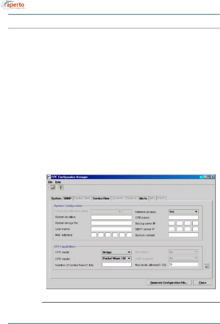
To configure subscriber equipment, click on the CPE icon on the WaveCenter Con-
figuration Manager home screen (Figure6-1). The CPE Configuration Manager will
open in a new window, as shown in Figure6-12.
There are nine tabs for subscriber equipment configuration, as shown in Figure6-12:
•System — Used to specify basic information about the subscriber equipment.
•SNMP — Used to control SNMP access to the subscriber equipment.
•Packet Filter — Not supported in R1P1.
•Service Flow — Used to define Service Flows for the subscriber.
•Classifier — Used to specify the classifiers that will cause packets to be
assigned to the various Service Flows.
•Routing — Not supported in R1P1.
•Alerts — Used to configure the subscriber equipment for email event alerts.
•NAT — Used to configure a subscriber Indoor Unit’s NAT routing.
•DHCP — Not supported in R1P1.
Figure6-12 CPE Opening Menu (System)

6–25070-20000340-01 Rev A
CHAPTER 6. BSU AND S UBSCRIBER CONFIGURATION
Configuring Subscriber System Parameters
Click on the System tab so that the screen illustrated in Figure6-12 is displayed.
Specify subscriber system parameters as indicated in Table6-L.
Table6-L CPE — System Parameters
Parameter Range
(and Default) Comments
Channel Center Frequency N/A Read-only field identifying the center frequency
established when the subscriber equipment was
initialized.
Network Access Yes or No
(Yes) Specify whether the subscriber will be allowed on
the network. This field may be set to No to essen-
tially disable subscriber equipment.
System Location Up to 79 characters
(no default) Enter text identifying the subscriber’s location.
CPE Name Up to 79 characters
(no default) Enter a name or description of the subscriber site.
System Image File N/A Identifies the software which should be running on
the Indoor Unit. If different software is running, the
subscriber Indoor Unit will attempt to download the
specified software from the TFTP server.
Syslog Server IP xxx.xxx.xxx.xxx decimal
(no default) If desired, enter the address of a syslog server
which will receive event logs directly from this sub-
scriber Indoor Unit.
User Name (no default) Enter a name for the subscriber.
MAC address 00:01:3b:xx:xx:xx
(no default) Complete the MAC address of the subscriber Indoor
Unit as identified by a label on the unit’s rear panel.
(All Aperto MAC addresses begin with 00:01:3b.)
SMTP Server IP xxx.xxx.xxx.xxx decimal
(no default) If desired, enter the address of a mail server which
will administer email alerts for this subscriber.
CPE Mode Bridge, Router, NAT
(Bridge) Specify the subscriber Indoor Unit model, and
whether the unit will function as a bridge, router, or
NAT router. (If the CPE Model specified does not
match the actual unit installed, the configuration file
will be rejected when it is downloaded to the sub-
scriber Indoor Unit. In R1P1, the PacketWave 130 is
the only model supported.)
CPE Model PW110, PW120,
PW130 (PW130)
Number of Service Flows 1 to 64
(no default) Specify the maximum number of service flows which
can be defined for this subscriber.
Encryption Not supported in R1P1.
IGMP Support Not supported in R1P1.
Max Hosts Allowed 1 to 20 Specify the maximum number of user hosts which
the subscriber Indoor Unit will support.
CHAPTER 6. BSU AND S UBSCRIBER CONFIGURATION
6–26070-20000340-01 Rev A
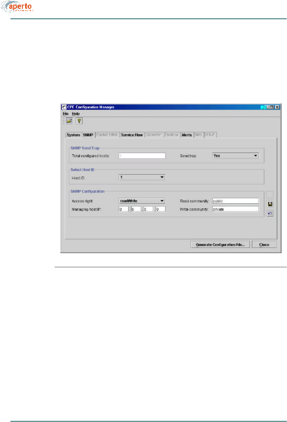
Configuring Subscriber SNMP Parameters
Click on the SNMP tab so that the screen illustrated in Figure6-13 is displayed.
Specify SNMP management parameters as indicated in Table6-M.
Figure6-13 SNMP Menu

6–27070-20000340-01 Rev A
CHAPTER 6. BSU AND S UBSCRIBER CONFIGURATION
Configuring Packet Filters
This feature is not supported in R1P1.
Table6-M CPE — SNMP Parameters
Parameter Range
(and Default) Comments
Total Configured Hosts 1 to 32 Read-only field indicating how many SNMP hosts
have been specified.
Send Trap Yes or No
(Yes)Specify whether SNMP traps will be sent to trap-
enabled hosts (per Access Right configurations).
Host ID 1 to 32 (increments as
instances are opened) Identifies the SNMP host being configured.
Access Right readOnly, readWrite,
roWithTraps,
rwWithTraps, trapsOnly
(readWrite)
Specify the SNMP access this master will have.
Host IP Address xxx.xxx.xxx.xxx decimal
(0.0.0.0) Specify the IP address of this SNMP manager.
Read Community Up to 79 characters
(public) Specify the name of the community which will have
read access to the subscriber Indoor Unit.
Write Community Up to 79 characters
(private) Specify the name of the community which will have
write access to the subscriber Indoor Unit.

CHAPTER 6. BSU AND S UBSCRIBER CONFIGURATION
6–28070-20000340-01 Rev A
6–29070-20000340-01 Rev A
CHAPTER 6. BSU AND S UBSCRIBER CONFIGURATION
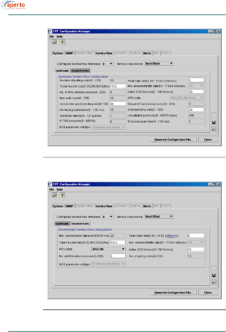
Figure6-14 Service Flow — Upstream Menu
Figure6-15 Service Flow — Downstream Menu

CHAPTER 6. BSU AND S UBSCRIBER CONFIGURATION
6–30070-20000340-01 Rev A
Table6-N CPE — Service Flow Upstream Parameters
Parameter Range
(and Default) Comments
Configured Service Flow
Reference Identifies service flow
displayed (1 to 64) Select from drop-down menu. (Menu identifies all
service flows which have been created. Maximum
may be less than 64 depending on)
Service Class Name Best Effort, CIR, CBR
(Best Effort) Select the class of service for this service flow from
the drop-down menu. (Must be the same for both
upstream and downstream.)
Number of Polling Slots 0 to 255
(10) Not supported in R1P1.
Token Bucket Size 0 to 25000 kbytes
(1522) Specify the size of the token bucket for this service
flow.
No. of ARQ Retransmis-
sions 0 to 255
(5) Not supported in R1P1.
Max. Null Count (CBR Only) 0 to 255
(10 Not supported in R1P1.
Unsolicited Grant Pending
Wait 0 to 100 frames
(20) Specify the grant waiting period for this service flow.
Normal Grant Interval 5 to 100 ms
(10) Not supported in R1P1.
Grant per Interval 0 to 127 grants
(1) Not supported in R1P1.
IP TOS Overwrite 0 to 65535
(0) Not supported in R1P1.
Peak Data Rate Menu: 64 to 8192 kbps
(0/BE & CIR, 64/CBR) Specify the peak data rate for this service flow
Min. Reserved Traffic Rate Menu: 64 to 8192 kbps
(blank) If the service class is CBR, specify the minimum
data rate for this service flow
Active QoS Timeout 0 to 100 frames
(20) Specify the active QOS timeout for this service flow.
ARQ State ARQ On:
ARG Off, Return ACKs;
ARQ Off, No ACKs
(ARQ On)
Not supported in R1P1.
Request/Transmission Pol-
icy 0 to 255
(0) Not supported in R1P1.
Grant Pending Wait 0 to 100 frames
(20) Not supported in R1P1.
Unsolicited Grant Size 0 to 100 frames
(20) Not supported in R1P1.
6–31070-20000340-01 Rev A
CHAPTER 6. BSU AND S UBSCRIBER CONFIGURATION
Tolerated Grant Jitter 5 to 100 ms
(5) Not supported in R1P1.
QoS Parameter Set Type Not supported in R1P1.
Table6-O CPE — Service Flow Downstream Parameters
Parameter Range
(and Default) Comments
Max. Downstream Latency 0 to 65535 ms
(20)
Token Bucket Size 0 to 25000 kbytes
(1522)
ARQ State ARQ On:
ARG Off, Return ACKs;
ARQ Off, No ACKs
(ARQ On)
No. of ARQ Retransmis-
sions 0 to 255
(6)
Peak Data Rate Menu: 64 to 8192 kbps
(0/BE & CIR, none/
CBR)
Min. Reserved Traffic Rate Menu: 64 to 7168 kbps
(64/CIR, none/BE &
CBR)
Active QoS Timeout 0 to 100 frames
(20)
No. of Polling Slots 0 to 255
(0)
QoS Parameter Set Type Provisioned Set, Active
Set, Provisioned and
Active (Provisioned Set)
Not supported in R1P1
Table6-N CPE — Service Flow Upstream Parameters (Continued)
Parameter Range
(and Default) Comments

CHAPTER 6. BSU AND S UBSCRIBER CONFIGURATION
6–32070-20000340-01 Rev A
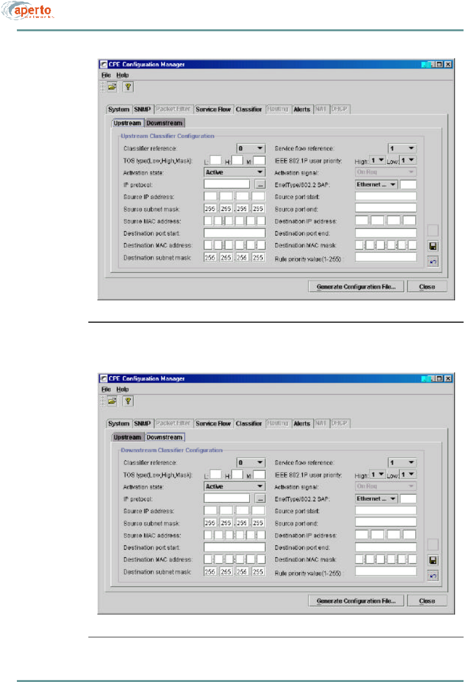
Configuring Service Flow Classifiers
In a multiservice environment, classifiers are used to direct subscriber traffic to dif-
ferent service flows. Therefore, until at least two service flows have been defined, the
Classifier tab will be grayed out.
Note that upstream and downstream traffic are separately assigned to service flows.
See Table6-P for definitions of the classifier parameters.
To define service flow classifiers:
1. Click on the Classifier tab and then the Upstream tab so that the screen illus-
trated in Figure6-16 is displayed.
2. Assign upstream traffic to a service flow as follows:
a. Specify the parameter(s) that will define the classifier.
b. Choose the service flow to which traffic matching this classifier will be
directed by selecting from the Service Flow Reference menu.
c. Click on the save instance icon when done.
3. Click on the Downstream tab so that the screen illustrated in Figure6-17 is
displayed. Assign downstream traffic to a service flow as follows:
a. Specify the parameter(s) that will define the classifier.
b. Choose the service flow to which traffic matching this classifier will be
directed by selecting from the Service Flow Reference menu.
c. Click on the save instance icon when done.
4. To define another set of upstream and downstream classifiers, click on the new
instance icon. Note that the Classifier Reference field will increment.
a. Click on the Upstream tab, choose the service flow to which traffic
matching this classifier will be directed by selecting from the Service
Flow Reference menu, alter parameters as desired, and click on the save
instance icon.
b. Click on the Downstream tab, choose the same service flow as for
upstream traffic from the Service Flow Reference menu, alter parameters
as desired, and click on the save instance icon.
5. Repeat step 4 until all classifiers have been defined.
Before generating the configuration file, be sure there is at least one upstream
classifier and one downstream classifier assigned to each service flow which has
been defined.
6–33070-20000340-01 Rev A
CHAPTER 6. BSU AND S UBSCRIBER CONFIGURATION
Figure6-16 Classifier — Upstream Menu
Figure6-17 Classifier — Downstream Menu

CHAPTER 6. BSU AND S UBSCRIBER CONFIGURATION
6–34070-20000340-01 Rev A
Table6-P CPE — Classifier Parameters
Parameter Range
(and Default) Comments
Classifier Reference N/A ID number of the current classifier; increments as
each new instance is opened.
Service Flow Reference Menu of existing SIDs
(0) Choose the service flow to which packets matching
this classifier will be assigned.
TOS Type (Low, High,
Mask) If desired, specify the matching parameters for the
IP ToS byte range and mask. An IP packet with IP
ToS byte value “ip-tos” matches this parameter if
tos-low <= (ip-tos AND tos-mask) <= tos-high.
IEEE 802.1P User Priority,
High and Low 1 to 7 for each
(1) Specify the high and low limits for user priority.
Activation State Inactive or Active
(Active) Specify whether this classifier is to be active or inac-
tive. (This allows classifiers to be defined, then
turned on or off.)
Activation Signal
IP Protocol * Any, ICMP-1, TCP-6,
UDP-17
(Any)
EnetType/802.2 SAP * (no default) Specify the Ethernet frame type:
For Version 2 or SNAP Ethernet Frame type, enter
a value from 10000 -to 1FFFF
For IEEE 802.2 Ethernet Frame Type, enter a value
from 20000 to 2FFFF
Source IP Address * xxx.xxx.xxx.xxx decimal
(no default) Specify a source by IP address.
Source Subnet Mask * xxx.xxx.xxx.xxx decimal
(255.255.255.255) Specify a destination subnetwork by entering an IP
subnet mask.
Source Port Start * 0 to 65535
(no default Specify a range of destination ports.
Source Port End * 0 to 65535
(no default
Source MAC Address * xx.xx.xx.xx.xx.xx hexa-
decimal (no default) Specify a source by MAC address.
Destination IP Address * xxx.xxx.xxx.xxx decimal
(no default) Specify a destination by IP address.
Destination Subnet Mask * xxx.xxx.xxx.xxx decimal
(255.255.255.255) Specify a destination subnetwork by entering an IP
subnet mask.

6–35070-20000340-01 Rev A
CHAPTER 6. BSU AND S UBSCRIBER CONFIGURATION
Configuring Routing Functions
Standard routing capability is not supported by the PacketWave 130. Therefore, this
menu is not supported in R1P1.
Destination Port Start * 0 to 65535
(no default Specify a range of destination ports.
Destination Port End * 0 to 65535
(no default
Destination MAC Address * xx.xx.xx.xx.xx.xx hexa-
decimal (no default) Specify a destination host by MAC address.
Destination MAC Mask * xx.xx.xx.xx.xx.xx hexa-
decimal (no default) Specify a range of destination hosts by MAC
address mask.
Rule Priority Value 0 to 255
(no default) Specify a priority value for this classifier rule. Rule
priority has to be unique for each classifier in the
system.
* All of these fields are optional, and may be specified as desired to define a classifier rule.
Table6-P CPE — Classifier Parameters (Continued)
Parameter Range
(and Default) Comments
CHAPTER 6. BSU AND S UBSCRIBER CONFIGURATION
6–36070-20000340-01 Rev A
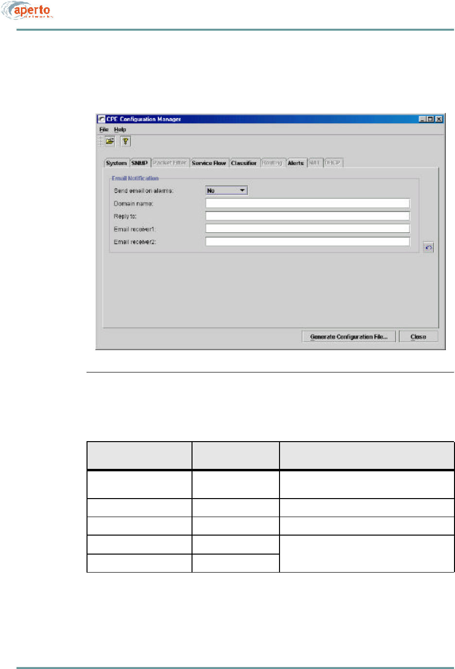
Configuring Subscriber Email Alerts
Click on the Alerts tab so that the screen illustrated in Figure6-18 is displayed.
Specify email alert parameters as indicated in Table6-Q.
Figure6-18 Alerts Menu
Table6-Q CPE — ALERTS Parameters
Parameter Range
(and Default) Comments
Send Email on Alarms Yes or No
(No)Specify whether email alert message will be sent. (If
No, the other fields will be unavailable.
Domain Name ?????? Specify the email domain name for the subscriber.
Reply To ???? Enter the sending email address for alert messages.
Email Receiver 1 any email address Enter the email address(es) to which alert mes-
sages will be sent.
Email Receiver 2 any email address
6–37070-20000340-01 Rev A
CHAPTER 6. BSU AND S UBSCRIBER CONFIGURATION
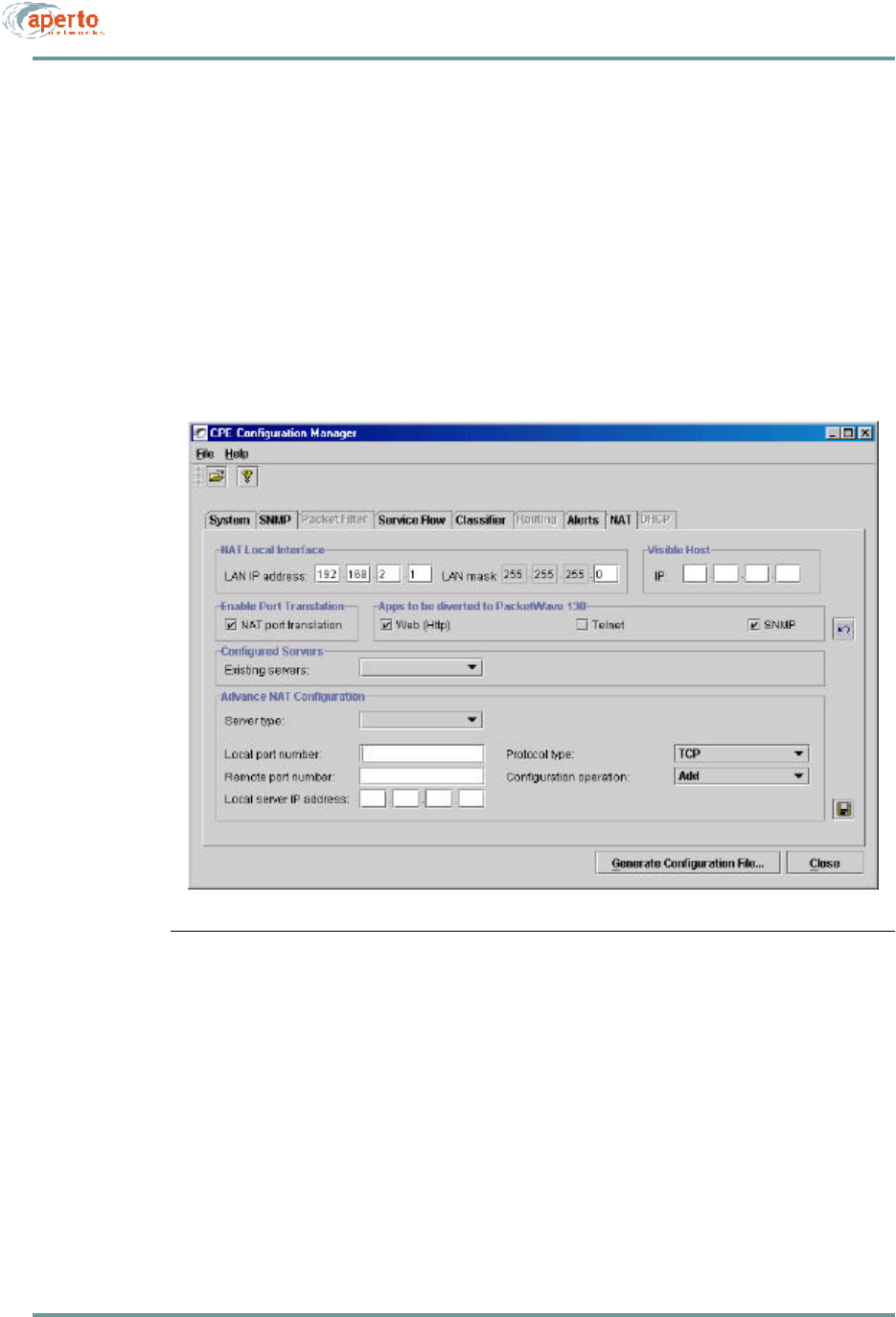
Configuring NAT Routing
Network Address Translation (NAT) routing is performed only if the subscriber
Indoor Unit is configured for NAT mode. If the subscriber Indoor Unit is configured
as a bridge, the NAT tab will grayed out.
To configure NAT routing, click on the NAT tab so that the screen illustrated in
Figure6-19 is displayed. Specify NAT parameters as indicated in Table6-R.
Figure6-19 NAT Menu

CHAPTER 6. BSU AND S UBSCRIBER CONFIGURATION
6–38070-20000340-01 Rev A
Configuring the Subscriber Indoor Unit’s DHCP Server
This menu is not supported in R1P1.
Table6-R CPE — NAT Parameters
Parameter Range
(and Default) Comments
LAN IP Address xxx.xxx.xxx.xxx decimal
(192.168.2.1) Enter the IP address of the subscriber Indoor Unit’s
Ethernet LAN interface. This will be the default gate-
way for the LAN and will typically follow the gateway
addressing convention.
LAN Mask xxx.xxx.xxx.xxx decimal
(255.255.255.0) Enter the subnet mask which defines the LAN
subnet.
Visible Host xxx.xxx.xxx.xxx decimal
(no default) Enter the IP address of a host on the LAN which will
respond to the subscriber Indoor Unit’s wireless
interface IP address.
Enable Port Translation checked or unchecked
(checked) Check the NAT Port Translation box to enable port
translation; uncheck the box to disable.
Apps to be diverted to
PacketWave 130 Web (checked)
Telnet (unchecked)
SNMP (checked)
Check boxes corresponding to applications which
are to be diverted to the PacketWave 100.
Existing Servers (Drop-down menu) Menu of servers defined on the LAN subnet.
Server Type FTP, HTTP, IMAP2,
SNMP, POP3, SMTP,
Telnet, TFTP, Other
(no default)
Use these fields to define (add or delete) servers on
the LAN subnet, and to specify the parameters of
the servers.
Local Port Number Read-only, per Server
Type
Remote Port Number Default follows Local
Port Number
Local Server IP Address xxx.xxx.xxx.xxx decimal
(192.0.1.0)
Protocol Type (Drop-down menu)
Configuration Operation Add or Delete
(Add)

6–39070-20000340-01 Rev A
CHAPTER 6. BSU AND S UBSCRIBER CONFIGURATION
OTHER CONFIGURATION METHODS
Only configuration changes made using the WaveCenter Configuration Manager can
affect the PacketWave System’s configuration file on the TFTP server.
A limited set of configuration changes can be made in real time via the Web and
SNMP interfaces. But such changes are not recorded in, and cannot be saved to, the
configuration files on the TFTP server. When the configured equipment (Base Station
Unit or subscriber Indoor Unit) is rebooted, it will revert to the parameters in the
stored configuration file, and all changes made via the Web interface or SNMP will
be lost.
Therefore, configuration changes via the Web Interface or SNMP are recommended
only for testing and troubleshooting purposes. Should a configuration change need to
be made permanent, you must use the WaveCenter Configuration Manager to update
the relevant configuration file on the TFTP server.
NOTE: If a configuration change is made to operating parameters using the Web or
SNMP interface, and then duplicated using the CM and saved to the TFTP server,
the change will essentially survive a reboot. This is a way to make permanent con-
figuration changes without immediately rebooting the system.

CHAPTER 6. BSU AND S UBSCRIBER CONFIGURATION
6–40070-20000340-01 Rev A

7–1070-20000340-01 Rev A
CHAPTER 7. NETWORK CONFIGURATION AND START-UP
7–2070-20000340-01 Rev A
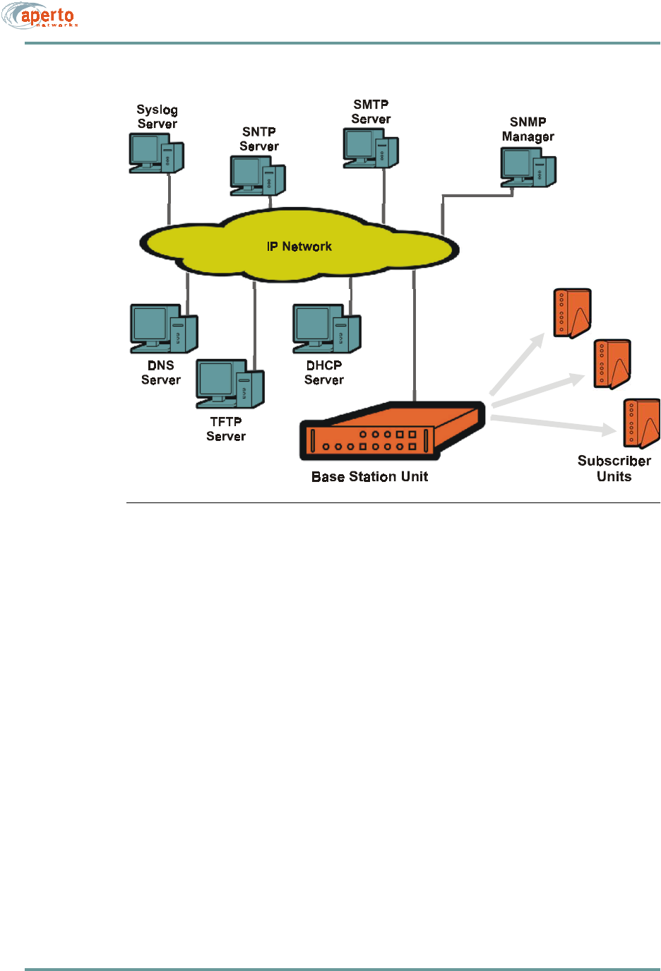
Figure 7-1 PacketWave System Servers
Required and Recommended Servers
Make sure that the Base Station Unit can access the following servers:
•DHCP Server — The server from which the Base Station Units and subscriber
Indoor Units obtain:
-IP addresses
-Subnet masks
-Default gateways
-TFTP server IP address
-Other server IP addresses
-BSU and SU configuration file names
NOTE: If the DHCP and the BSU are not on the same subnet, the BSU’s subnet
must include a DHCP relay agent to pass the BSU’s DHCP requests to the proper
DHCP server. Also, subscriber Indoor Units can collectively be assigned a different
DHCP server than the one used by the BSU.

7–3070-20000340-01 Rev A
CHAPTER 7. NETWORK CONFIGURATION AND START-UP
•TFTP Server — The server from which the Base Station Units and subscriber
Indoor Units download configuration files.
•SNTP Server — A Simple Network Time Protocol server is recommended for
synchronizing the PacketWave Base Station Unit’s date and time with other
systems on the network. (If there is no SNTP server, the Base Station Unit’s
date and time must be set via the Web interface.)
NOTE: Subscriber Indoor Units obtain the date and time from the BSU. Whenever
the BSU’s date/time is changed, it downloads the new date/time to all subscriber
Indoor Units.
•DNS Server — Access to a DNS server is necessary for the resolution of
Internet domain names.
Optional Servers
Depending on the features and functions to be implemented, additional servers may
be required. These servers can be identified in the DHCP server configuration or in
the BSU configuration.
NOTE: If different servers of a particular type are identified, the server identified in
the DHCP configuration will prevail.
•SMTP Server — A Simple Mail Transfer Protocol server is required for the
emailing of event alerts. (Alternatively, this server can be identified in the BSU
configuration.)
•Syslog Server — A syslog server may be specified for logging of event mes-
sages from the Base Station Units. (Alternatively, this server can be identified
in the BSU configuration.)
•DHCP Server for CPE — A different DHCP server than the one used for the
BSU can be specified for Subscriber Indoor Units.
•SNMP Managers — All Base Station Units and subscriber Indoor Units
include SNMP (Simple Network Management Protocol) agents which can be
accessed by an SNMP manager for monitoring and limited configuration.
The SMTP, Syslog, and CPE DHCP servers can be identified via the WaveCenter
Configuration Manager’s BSU — MAIN — IP Servers screen. (The SMTP and
Syslog servers can also be specified in the DHCP server’s configuration file.) The
SNMP managers are identified via the BSU — SNMP and CPE — SNMP screen
CHAPTER 7. NETWORK CONFIGURATION AND START-UP
7–4070-20000340-01 Rev A
Preparing the TFTP Server
The PacketWave System uses the TFTP server for storing files and downloading them
to Base Station Units and subscriber Indoor Units on request. Any third-party or pub-
lic domain TFTP server may be used.
Ensure that configuration files for all Base Station Units and subscriber Indoor Units
are stored in the default directory (typically \tftpboot) of the TFTP server, and that the
TFTP server is running.
Configuring the DHCP Server
A variety of DHCP servers are available. Their configurations follow the same general
principles, but vary in implementation, terminology, and user interfaces. DHCP con-
figuration should be performed by personnel knowledgeable about both DHCP in gen-
eral and the particular DHCP server to be used. Whichever DHCP server is employed,
it should be configured to include the parameters identified in Table 7-A.
CAUTION: Take special care to ensure that the BSU and subscriber configu-
ration file names entered in the DHCP configuration are exactly
the same as the files created using the WaveCenter Configuration
Manager and stored on the TFTP server. A newly-installed unit
will not be able to operate properly if it cannot locate and down-
load its configuration file.
Table 7-A DHCP Configuration Requirements
Servers Required: TFTP
Recommended: SNTP, DNS
Optional: SNMP, SMTP, POP3
Subnets (Scopes) Subnets / Subnet Masks
Routers / Gateways
Each Base Station Unit Hardware Ethernet / MAC address
Fixed IP address for backhaul interface
configuration file name
Each Subscriber Indoor Unit Hardware Ethernet / MAC address
Fixed IP address for wireless interface
configuration file name
Subscriber Hosts IP addresses if the subscriber Indoor Unit functions as a bridge
DNS server if the subscriber Indoor Unit functions as a NAT router

7–5070-20000340-01 Rev A
CHAPTER 7. NETWORK CONFIGURATION AND START-UP
SYSTEM START-UP
Once all of the configuration files have been created, start the PacketWave System by
performing the following steps:
1. Verify that all of the configuration files have been saved in the default directory
on the TFTP server.
2. Verify that the TFTP server is running and accessible.
3. Verify that the DHCP server has been configured for network addresses and for
all BSUs and subscribers.
4. Verify that the DHCP server is running and accessible.
5. Boot the Base Station Unit. It will download its configuration, obtain its IP
address, and initialize automatically.
6. When the Base Station Unit has finished initializing, boot the subscriber Indoor
Units.
7. Initialize each subscriber Indoor Unit using the CPE Installation Tool, as
described in the PacketWave 100 Series Subscriber Equipment Installation and
Operation manual. When a subscriber Indoor Unit has been initialized, it will
download its configuration, obtain IP addresses, and join the network.
ADDING BASE STATION UNITS AND/OR SUBSCRIBERS
To add one or more Base Station Units and/or subscribers to an existing cell:
1. Launch the WaveCenter Configuration Manager.
2. Use the Configuration Manager to create configuration files for the new
device(s) as described in Chapter 6.
3. Save or copy the configuration file(s) to the default directory of the TFTP
server.
4. Add the required information about the device(s) in the DHCP server’s config-
uration file.
5. Boot the new devices.

CHAPTER 7. NETWORK CONFIGURATION AND START-UP
7–6070-20000340-01 Rev A
OTHER CONFIGURATION METHODS
Only configuration changes made using the WaveCenter Configuration Manager
affect the PacketWave System’s configuration data base.
A limited set of configuration changes can be made in real time via the Web and
SNMP interfaces, but such changes are not permanently stored. When the configured
equipment (Base Station Unit or subscriber Indoor Unit) is rebooted, it will revert to
the stored configuration, and all changes made via the Web interface or SNMP will
be lost.
Therefore, configuration changes via the Web Interface or SNMP are recommended
only for testing and troubleshooting purposes. Should a permanent configuration
change need to be made, you must use the WaveCenter Configuration Manager to
update the relevant configuration files on the TFTP server.

8–1070-20000340-01 Rev A
8
MANAGEMENT INTERFACES
The PacketWave system supports real-time monitoring and limited “on-the-fly” con-
figuration changes via a Web-browser-accessed Graphical User Interface (GUI) and
SNMP. There is also a simple command line interface (CLI) for basic troubleshooting
and debugging.
WEB INTERFACE (GUI)
Each Base Station Unit and Subscriber Unit includes a Java-based graphical user
interface (GUI) which runs on a standard Web browser (Netscape 4.74 or higher, or
Internet Explorer 5.0). Functions of the Web GUI include:
•Viewing network topology.
•Monitoring status and performance.
•Reviewing configuration.
•Making basic configuration changes.
•Resetting Base Station Units, BSU wireless interfaces (WSSs), and subscriber
Indoor Units.

CHAPTER 8. MANAGEMENT INTERFACES
8–2070-20000340-01 Rev A
Accessing the Web Interface
To access the graphical user interface:
1. Establish a connection and open your Web browser.
2. Enter the URL, http://<BSU IP address>/bsc.htm.
3. Respond to the user name prompt with Aperto and to the password prompt
with Aperto.
NOTE: The user name and password are case-sensitive, so be sure to capitalize the
A in Aperto.
4. If the browser prompts that it needs to load a plug-in, allow it to do so.
5. Wait for the Web interface home page to open, as shown in Figure8-1.
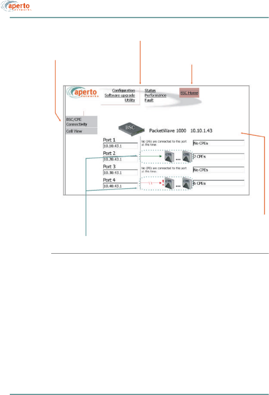
The Web GUI pages share the basic elements identified in Figure8-1.
Using the Base Station Unit’s Web GUI
When you open the BSU’s Web GUI, you are at the BSU Home Page shown in
Figure8-1. A main menu and submenus allow you to navigate easily among the var-
ious BSU pages.
Network Views
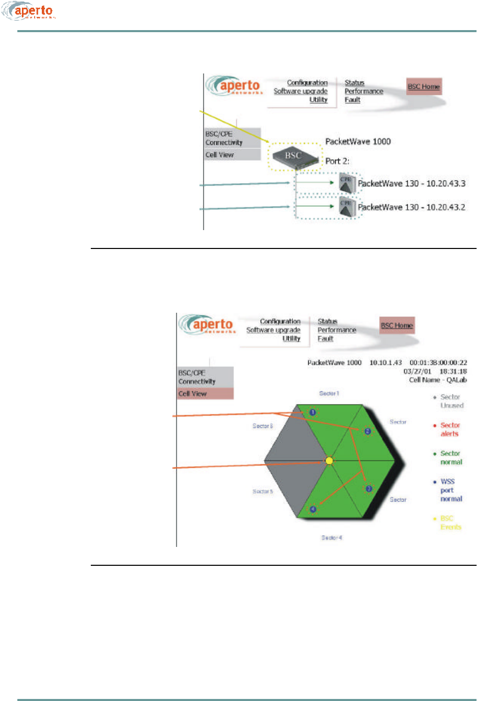
From the BSU Home Page, you can view the BSU and its wireless interfaces. Hyper-
links allow you to navigate through the BSU connections as indicated in Figure8-1
through Figure8-3.
The first time you select the Cell View page (Figure8-3), your browser may
prompt that it wants to download Java applets. Click on the OK button to allow
the download. The applets will then be cached in the browser, so downloading
will not be required in the future.
The connectivity views provide a quick way to identify the configured Base Station
Units, sectors (WSS), and subscribers, and to check their status. The arrows pointing
to the subscriber Indoor Units in Figure8-1 and Figure8-2 indicate wireless channel
status: green if good or red if down.
Color-coding of the cell view, shown in Figure8-3, is indicated by the legend on the
cell view page.
Status indications on the topology views are updated dynamically every 30
seconds.
8–3070-20000340-01 Rev A
CHAPTER 8. MANAGEMENT INTERFACES
Figure8-1 BSU Home: BSU/SU Connectivity, All Wireless Ports
Submenu Return-to-Home-Page Button
Main Menu
Hyperlinks
Display Header
(may include model, IP address, MAC address, date and time)
(down to selected port; see Figure 8-2)
CHAPTER 8. MANAGEMENT INTERFACES
8–4070-20000340-01 Rev A
Figure8-2 BSU Home: BSU/SU Connectivity, Select Port
Figure8-3 BSU Home: Cell View
Hyperlink
Hyperlinks
(back to BSU level;
see Figure 8-1)
(down to CPE level;
see Figure 8-19)
Hyperlink
Hyperlinks
(back to BSU level;
(to WSS Config;
see Figure 8-7)
see Figure 8-1)
8–5070-20000340-01 Rev A
CHAPTER 8. MANAGEMENT INTERFACES
Configuration Pages
The Web GUI lets you check, and in some cases alter, the configuration of the Base
Station Unit. There are five configuration pages which may be displayed, as indicated
by the submenu at the left of the page; they are illustrated in Figure8-4 through
Figure8-8.
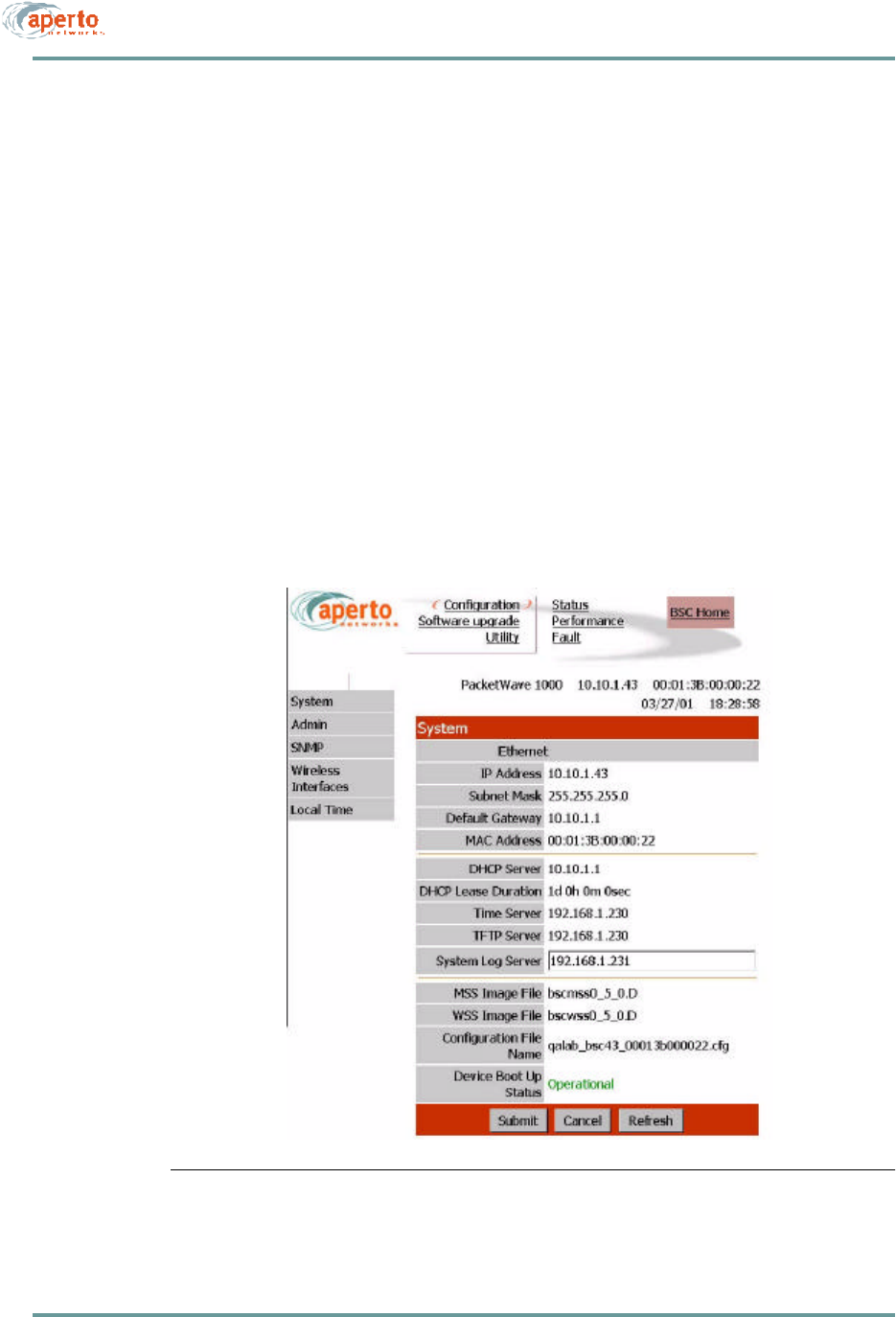
System Configuration
As shown in Figure8-4, the system configuration page identifies:
•Ethernet parameters
•DHCP and other server settings
•Operating software and configuration files, and current boot status.
Only the IP address of the System Log Server can be altered via this page. Click on
the Submit button to activate any change made on this page.
Figure8-4 System Configuration Page
CHAPTER 8. MANAGEMENT INTERFACES
8–6070-20000340-01 Rev A
Administrative Configuration
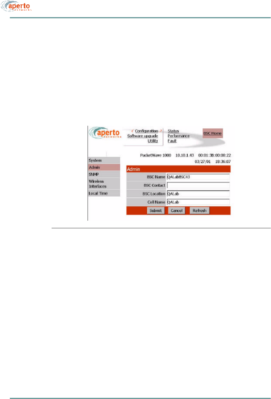
As shown in Figure8-5, the administrative configuration page allows viewing and
altering of text fields related to BSU and cell administration. These text fields can be
used for whatever information system administrators deem useful.
Click on the Submit button to activate any changes made on this page.
Figure8-5 Administrative Configuration Page

8–7070-20000340-01 Rev A
CHAPTER 8. MANAGEMENT INTERFACES
CHAPTER 8. MANAGEMENT INTERFACES
8–8070-20000340-01 Rev A
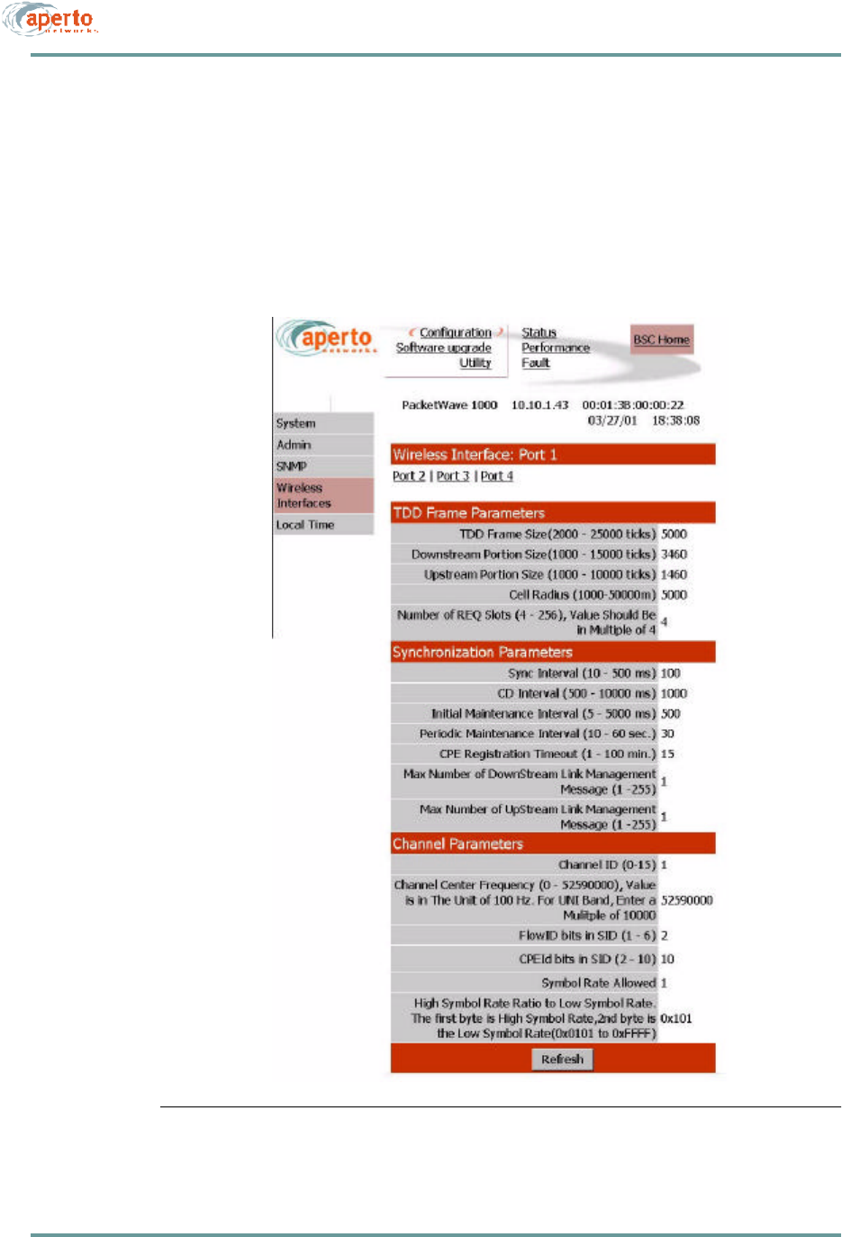
Wireless Port Configuration
As shown in Figure8-7, the wireless interface configuration page displays framing,
sync, and channel parameters. These advanced parameters cannot be changed in the
Web GUI; they can be altered only via the WaveCenter Configuration Manager, as
described in Chapter 6.
Figure8-7 WSS Configuration Page
8–9070-20000340-01 Rev A
CHAPTER 8. MANAGEMENT INTERFACES
Local Time Configuration
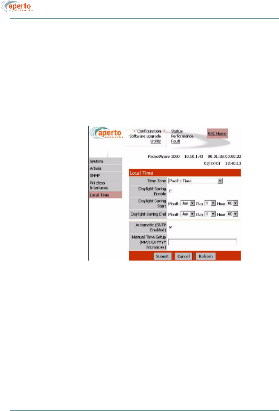
As shown in Figure8-8, the local configuration page allows the specification of the
local time zone and daylight savings time options. These adjustments will be applied
to the time received from the Base Station Unit’s SNTP server.
Alternatively, the obtaining of system time from the SNTP server can be disabled, and
the time entered on this page.
Click on the Submit button to activate any changes made on this page.
Figure8-8 Time Configuration Page
Software Upgrade Options
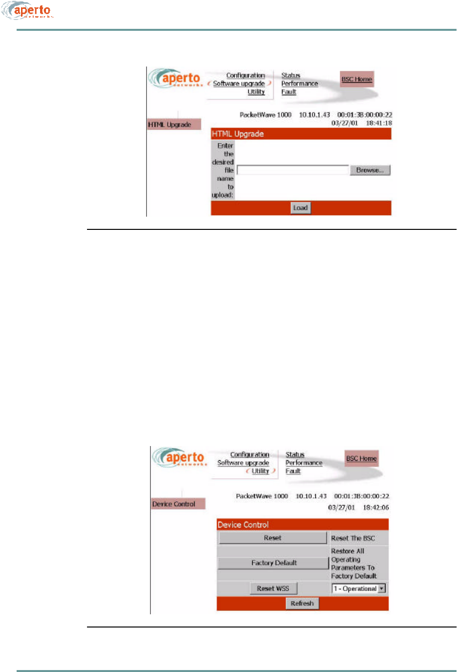
The HTML upgrade page illustrated in Figure8-9 lets you upgrade the Web GUI by
writing new pages from files to the BSU. For example, you might have pages trans-
lated into a language other than English which you want to load in place of the
English-language pages.
If you have an HTML page to upload, you can type in the file name or browse for it.
When the file name is specified, click on the Load button to load the file into the Base
Station Unit’s Web GUI agent.
CHAPTER 8. MANAGEMENT INTERFACES
8–10070-20000340-01 Rev A
Figure8-9 HTML Upgrade Page
Device Control Utilities
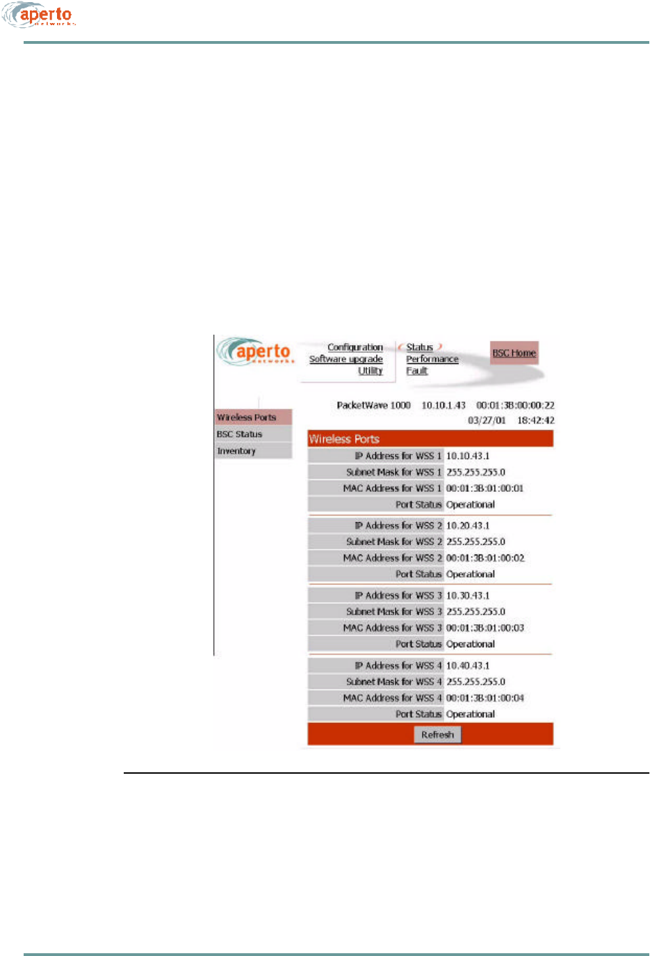
The device control page, illustrated in Figure8-10, provides access to several impor-
tant functions:
•Resetting the entire BSU.
•Resetting a selected WSS.
•Restoring factory defaults for all BSU configuration options.
The interface will prompt for confirmation before performing any selected functions.
Figure8-10 Device Control Page
8–11070-20000340-01 Rev A
CHAPTER 8. MANAGEMENT INTERFACES
Status Displays
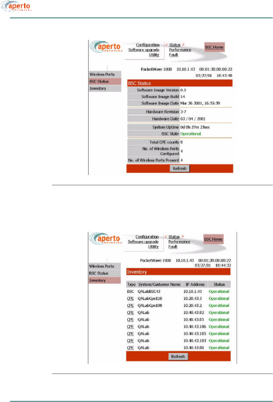
The BSU Web GUI includes the status pages shown in Figure8-11 through
Figure8-13. These provide a snapshot of the current status of the Base Station Unit,
its WSSs, and its connected subscribers (CPE).
NOTE: The data base used to generate these pages is updated in real time. However,
the pages do not update dynamically; you must click on the Refresh button to see
later status.
No configuration or other operation can be initiated from these pages.
Figure8-11 Wireless Port Status Page
CHAPTER 8. MANAGEMENT INTERFACES
8–12070-20000340-01 Rev A
Figure8-12 BSU Status Page
Figure8-13 Inventory Page
8–13070-20000340-01 Rev A
CHAPTER 8. MANAGEMENT INTERFACES
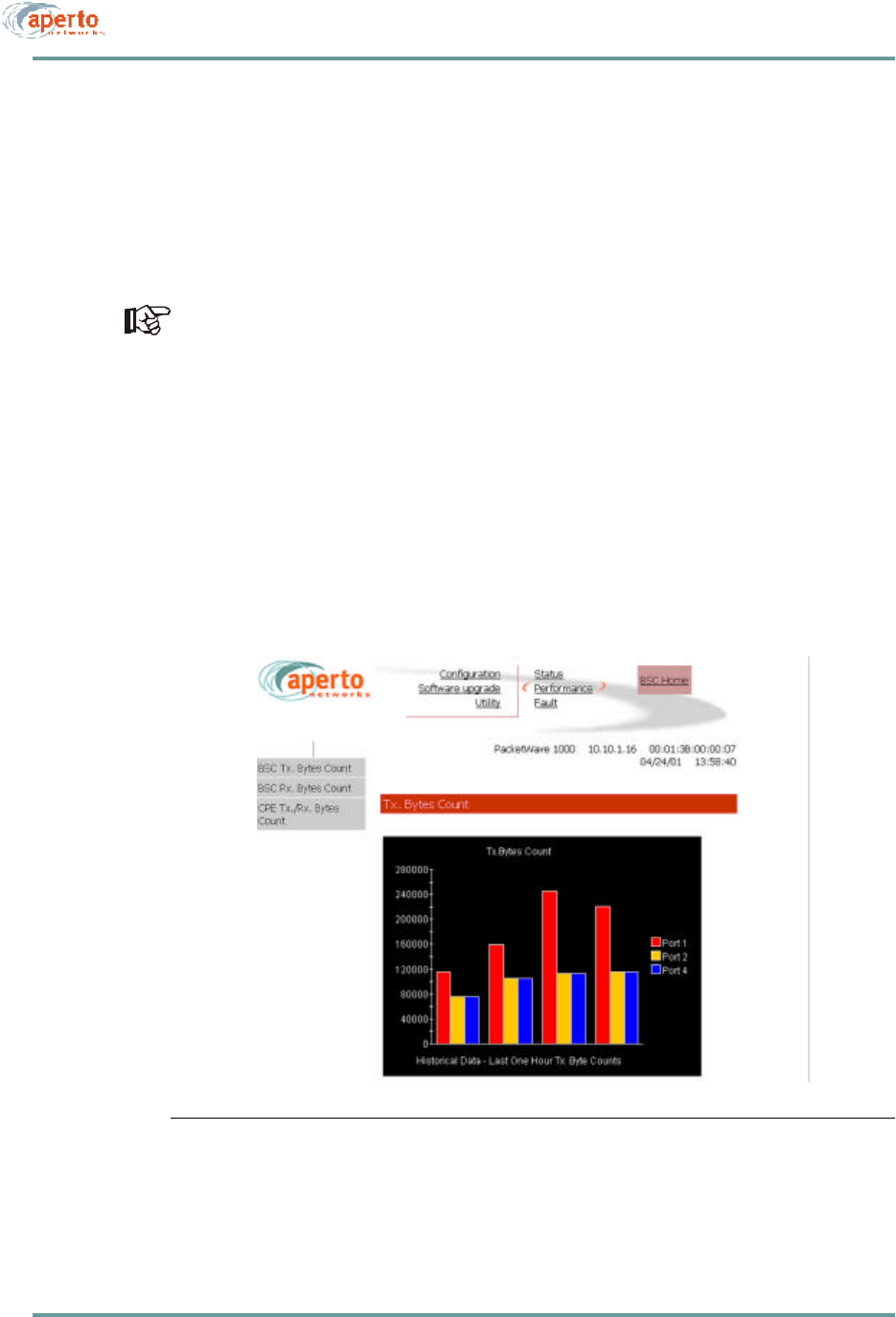
Performance Monitoring
The BSU Web GUI provides wireless channel performance information on the pages
illustrated in Figure8-14 through Figure8-16.
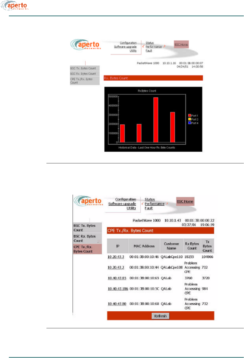
As shown in Figure8-14 and Figure8-15, transmitted and received byte counts are
presented graphically for all wireless ports (WSS).
These data base used to generate these displays is updated in real time, and the
pages are automatically updated every 30 seconds.
As shown in Figure8-16, transmitted and received byte counts for all subscribers in
all sectors (wireless ports) are listed in a text format.
NOTE: The data base used to generate this page is updated in real time. However,
the pages do not update dynamically; you must click on the Refresh button to see
later status.
Figure8-14 BSU Transmitter Performance Page
CHAPTER 8. MANAGEMENT INTERFACES
8–14070-20000340-01 Rev A
Figure8-15 BSU Receiver Performance Page
Figure8-16 BSU CPE Performance Page
8–15070-20000340-01 Rev A
CHAPTER 8. MANAGEMENT INTERFACES
Fault Reporting
The BSU fault reporting functions include an event log and email configuration, as
shown in Figure8-17 and Figure8-18.
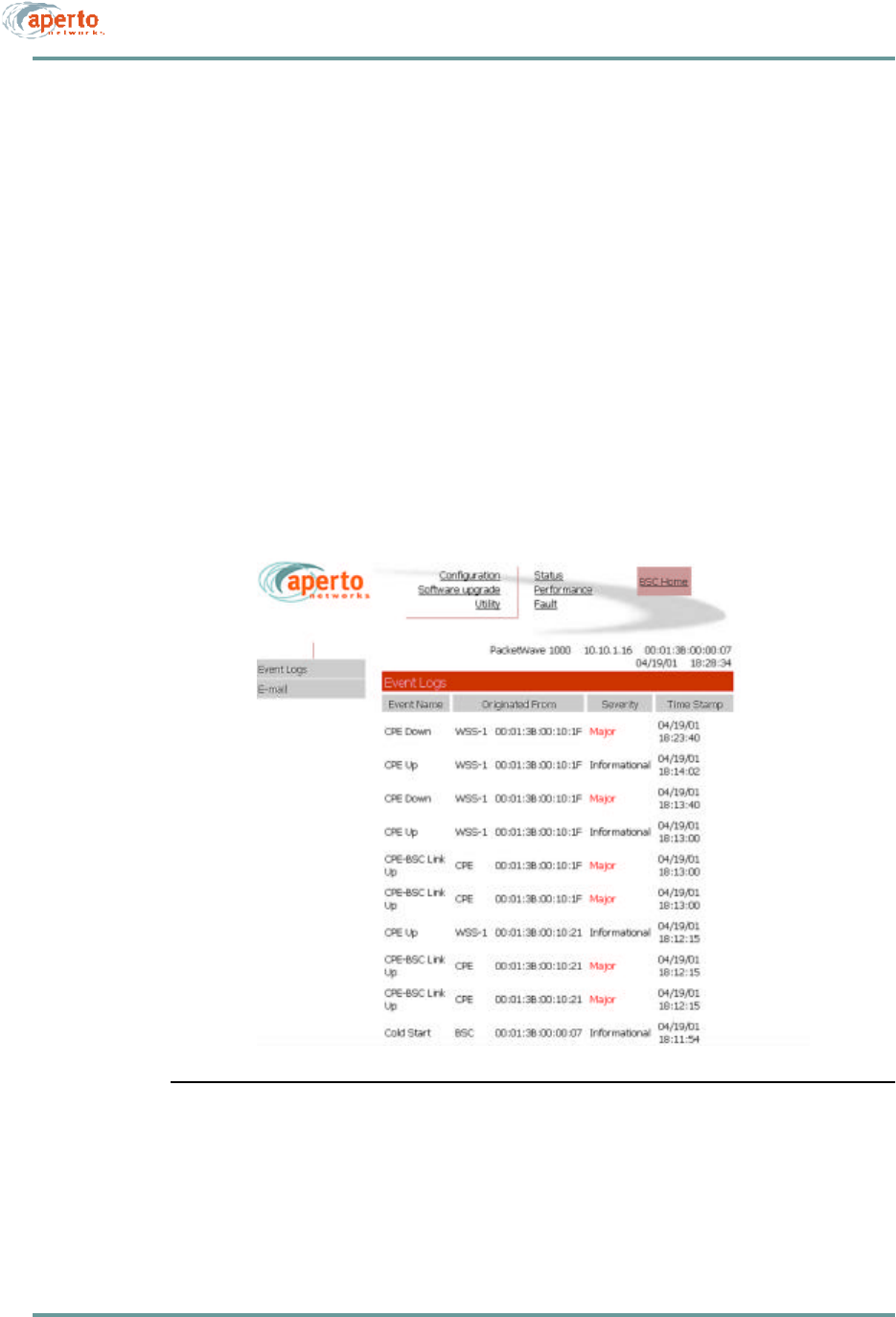
Event Log Page
The event log page, shown in Figure8-17, includes all logable events reported by the
Base Station Unit and its connected subscribers.
NOTE: The data base used to generate the log is updated in real time. However, the
pages do not update dynamically; you must click on the Refresh button to see later
status.
You can empty the log by clicking on the Clear All Events button.
Figure8-17 BSU Event Log Page
CHAPTER 8. MANAGEMENT INTERFACES
8–16070-20000340-01 Rev A
E-mail Page
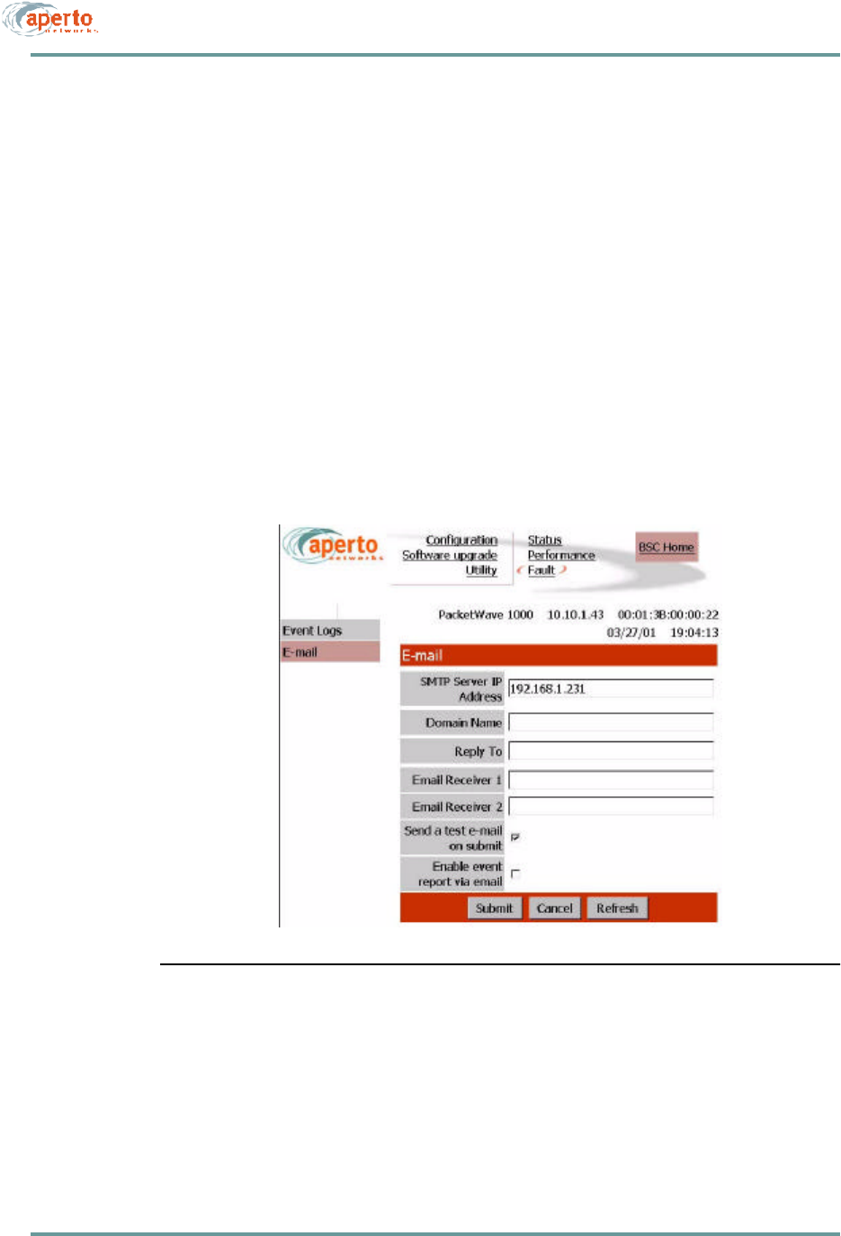
As shown in Figure8-18, the E-mail configuration page allows the viewing and alter-
ing of Email event reporting parameters:
•The address of the SMTP server (may be configured here, on the DHCP server,
or in the BSU configuration).
•The BSU’s E-mail domain name.
•Reply-to and receiver E-mail addresses.
•A test E-mail may be sent.
•Event reporting via E-mail may be turned on and off as desired.
Click on the Submit button to activate any changes made on this page.
Figure8-18 BSU Email Configuration Page
8–17070-20000340-01 Rev A
CHAPTER 8. MANAGEMENT INTERFACES
Using the Subscriber Indoor Unit’s Web GUI
The subscriber Indoor Unit’s GUI may be accessed via the BSU Web GUI (see
Figure8-2 and Figure8-3), or by directly addressing the subscriber Indoor Unit
(http://<wireless interface IP address>/cpe.htm). In either case, a new network con-
nection is being requested, so the system prompts for a user name and password.
Respond to each prompt with Aperto.
NOTE: The user name and password are case-sensitive
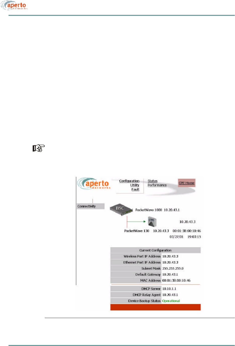
The subscriber (CPE) home page is illustrated in Figure8-19. It provides access to a
range of pages similar to those for the Base Station Unit.
As shown in Figure8-19, the subscriber (CPE) home page provides a graphical rep-
resentation of BSU-to-subscriber equipment connectivity. The arrow pointing to the
subscriber Indoor Unit icon indicates wireless channel status: green if good or red if
down.
Status indications on the connectivity view are updated dynamically every 30 sec-
onds.
Figure8-19 Subscriber Home Page: Connectivity View
CHAPTER 8. MANAGEMENT INTERFACES
8–18070-20000340-01 Rev A
Configuration Pages
The Web GUI lets you check, and in some cases alter, the configuration of the
subscriber equipment. There are four configuration pages which may be displayed, as
indicated by the submenu at the left of the page; they are illustrated in Figure8-20
through Figure8-23.
NOTE: NAT configuration applies only to PacketWave 120 and 130 models.
System Configuration
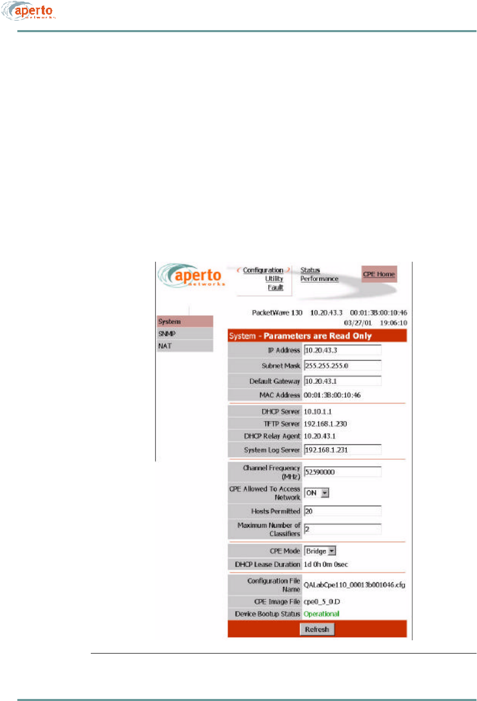
As shown in Figure8-20, the system configuration page provides an overview of the
subscriber’s wireless network connection and operating parameters. These parameters
are read-only.
Figure8-20 Subscriber System Configuration Page
8–19070-20000340-01 Rev A
CHAPTER 8. MANAGEMENT INTERFACES
SNMP Configuration
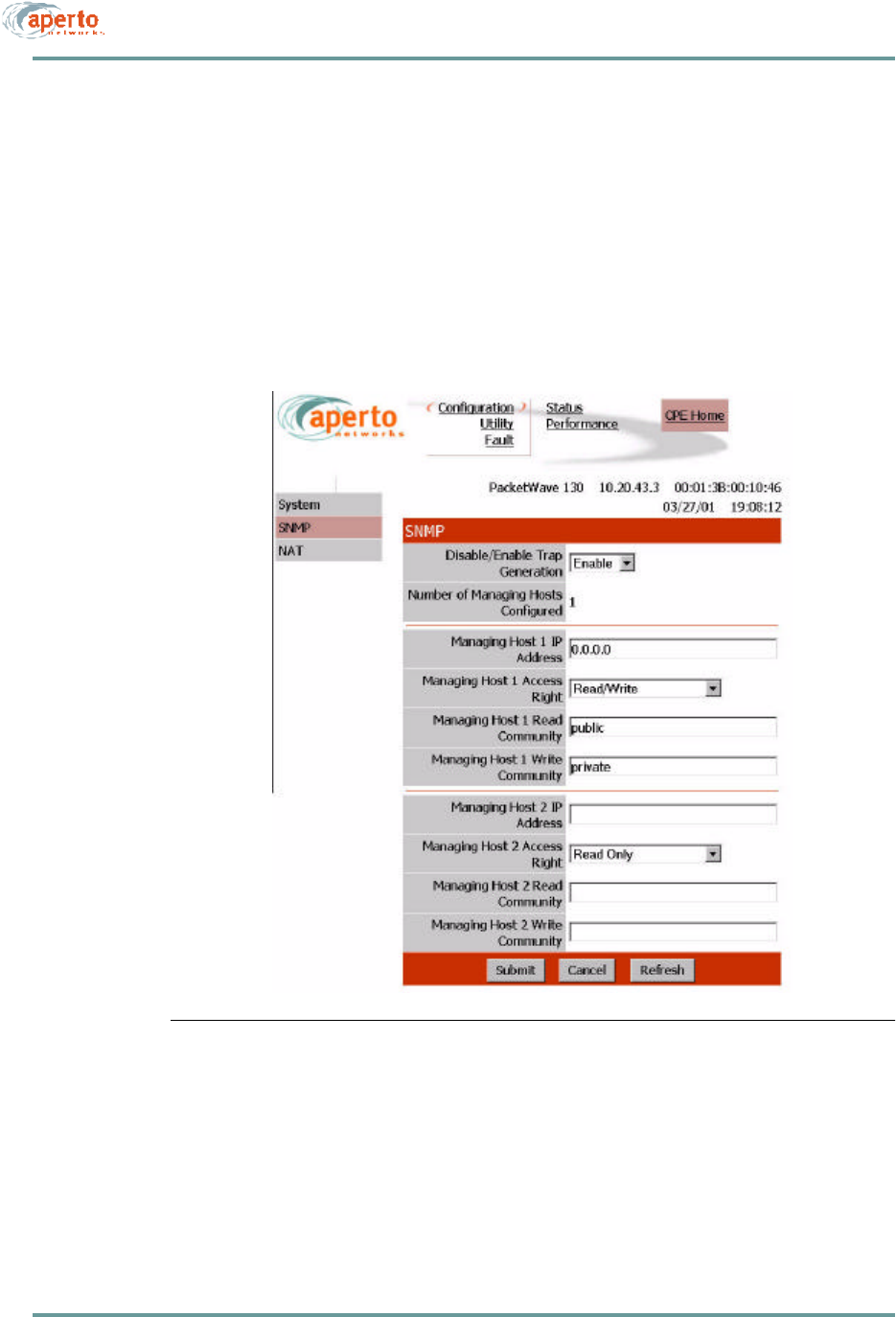
As shown in Figure8-21, the SNMP configuration page allows the viewing and alter-
ing of the subscriber Indoor Unit’s SNMP parameters:
•Whether traps will be generated by the Indoor Unit.
•What SNMP manager(s) will be recognized, and what level of access they will
have.
Click on the Submit button to activate any changes made on this page.
Figure8-21 Subscriber SNMP Configuration Page
CHAPTER 8. MANAGEMENT INTERFACES
8–20070-20000340-01 Rev A
NAT Configuration
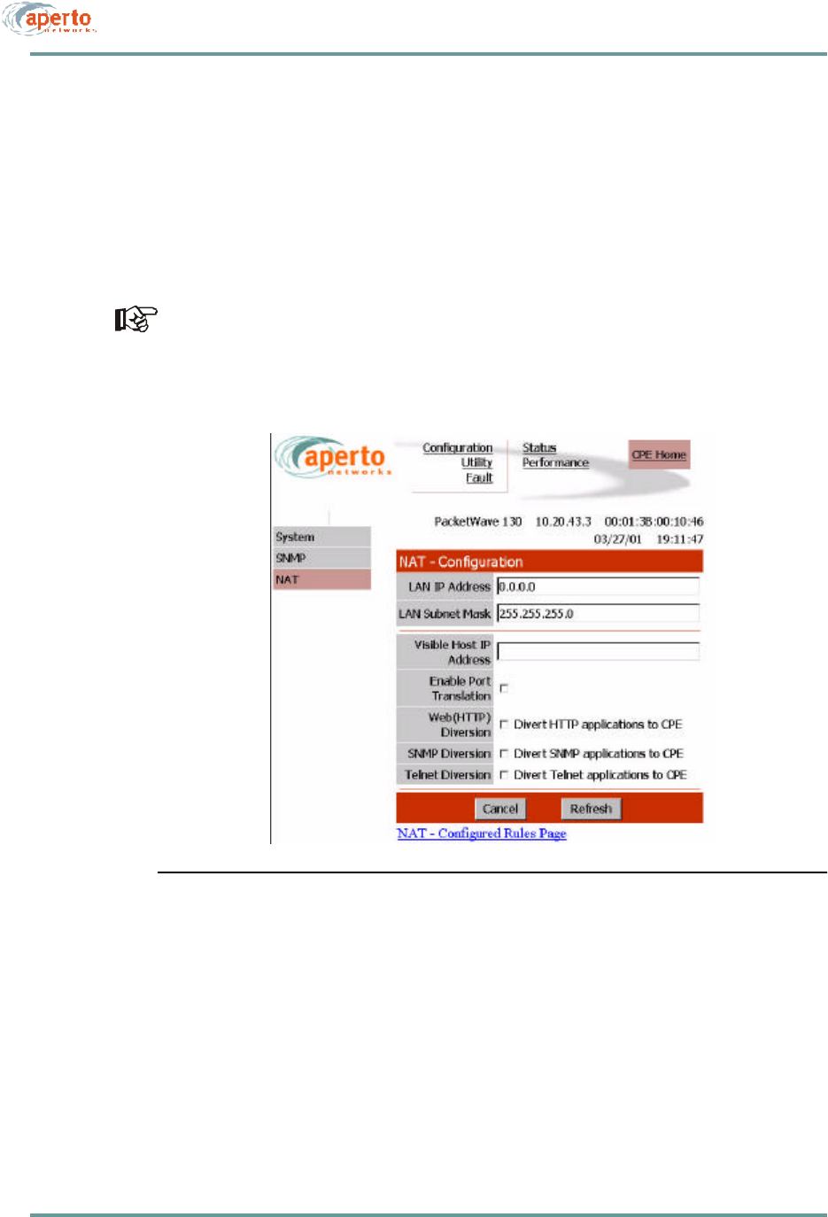
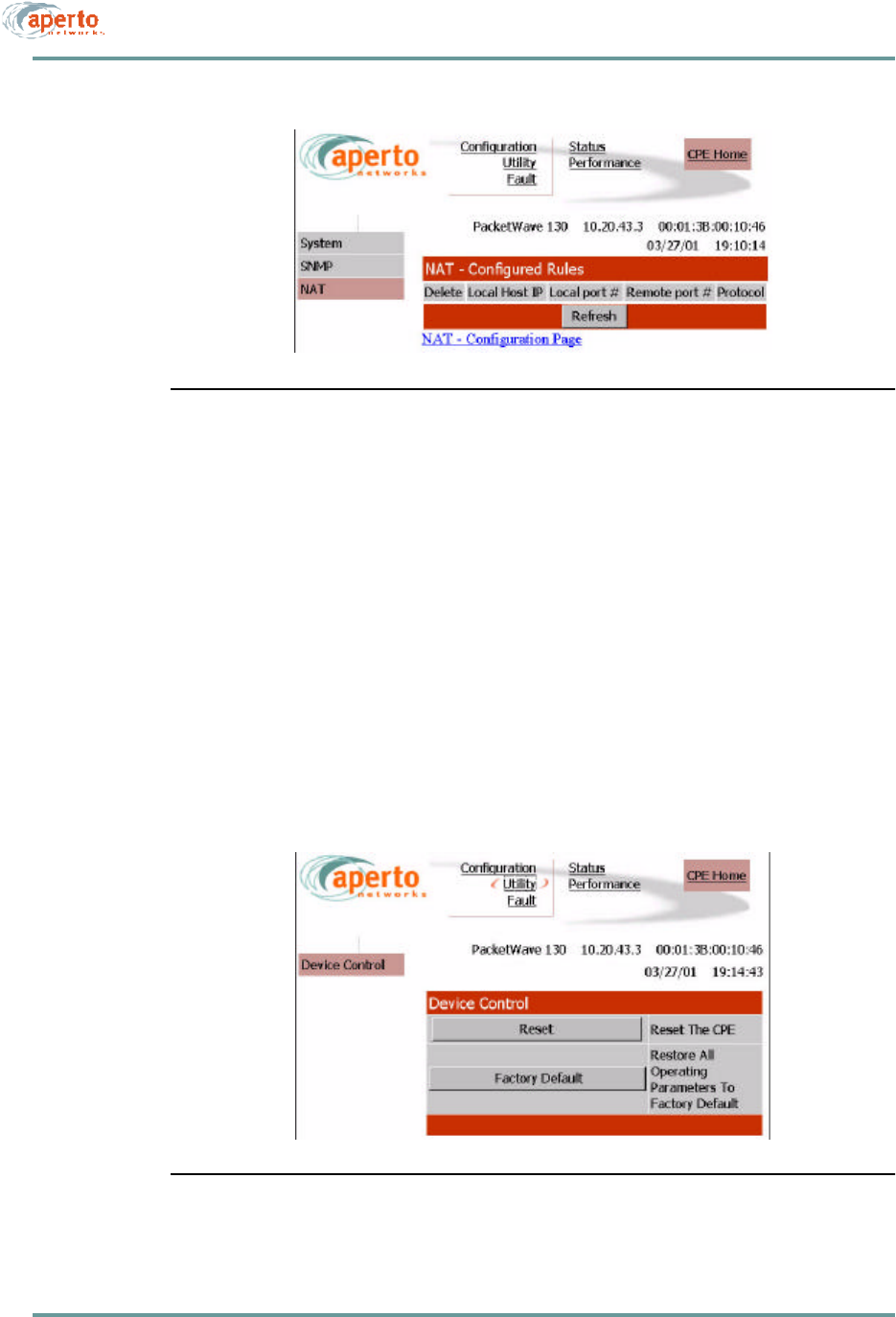
As shown in Figure8-22 and Figure8-23, there are two configuration pages related
to NAT (Network Address Translation) routing by the subscriber Indoor Unit. These
read-only pages apply only when the Indoor Unit is in NAT mode.
To move between the two NAT configuration pages, click on the hyperlinks at the
bottoms of the pages.
NAT configuration should be performed by a knowledgeable network
administrator.
Figure8-22 Subscriber NAT — Configuration Page
8–21070-20000340-01 Rev A
CHAPTER 8. MANAGEMENT INTERFACES
Figure8-23 Subscriber NAT — Configured Rules Page
Device Control Utilities
The device control page, illustrated in Figure8-24, provides access to a pair of impor-
tant functions:
•Resetting the subscriber Indoor Unit.
•Restoring factory defaults for all subscriber equipment configuration options.
The interface will prompt for confirmation before performing a selected function.
Figure8-24 Subscriber Device Control Page
CHAPTER 8. MANAGEMENT INTERFACES
8–22070-20000340-01 Rev A
Fault Reporting
The subscriber fault reporting functions include an event log and email configuration,
as shown in Figure8-25 and Figure8-26.
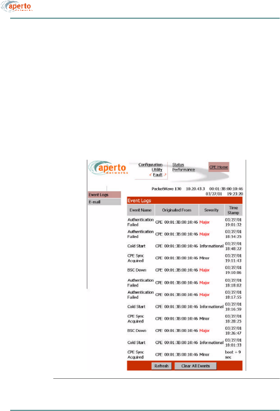
Event Log Page
The event log page, shown in Figure8-25, includes all logable events reported by the
subscriber Indoor Unit.
NOTE: The data base used to generate the log is updated in real time. However, the
pages do not update dynamically; you must click on the Refresh button to see later
status.
You can empty the log by clicking on the Clear All Events button.
Figure8-25 Subscriber Event Log Page

8–23070-20000340-01 Rev A
CHAPTER 8. MANAGEMENT INTERFACES
CHAPTER 8. MANAGEMENT INTERFACES
8–24070-20000340-01 Rev A
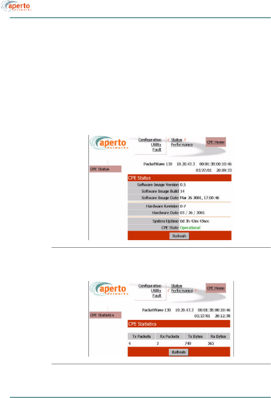
Status and Performance Statistics
The subscriber (CPE) status page, shown in Figure8-27, identifies the subscriber
Indoor Unit, its software and hardware, and its current operational status.
As shown in Figure8-28, the performance page provides transmit and receive statis-
tics in a table format.
NOTE: The data used to generate these pages is updated in real time. However, the
pages do not update dynamically; you must click on the Refresh button to see new
information. No configuration or other operation can be initiated from these pages.
Figure8-27 Subscriber Status Page
Figure8-28 Subscriber Performance Page

8–25070-20000340-01 Rev A
CHAPTER 8. MANAGEMENT INTERFACES
SNMP
Each subscriber Indoor Unit includes an SNMP agent. Each Base Station Unit
includes an SNMP agent plus a proxy agent for the subscriber Indoor Units. The
agents support the following MIBs:
•SNMP MIB (RFC 1157)
•MIB II (RFC 1213)
•Aperto private MIB
•Additional MIBs, as appropriate, for plug-in backhaul modules.
The complete MIBs are provided on the PacketWave CD-ROM, and are available on
the Aperto Web site, www.apertonet.com.
The SNMP agents support trap reporting. Trap-reporting parameters can be specified
via the Configuration Manager and the Web GUI as well as via SNMP.
NOTE: SNMP parameters are read-only in R1P1.
SYSLOG
The Base Station Unit and subscriber Indoor Unit supports logging of event messages
to a designated server according to the Syslog protocol. The Syslog server may be
identified in the DHCP configuration or the BSU and SU configuration files.
COMMAND LINE INTERFACE (CLI)
Each Base Station Unit and subscriber Indoor Unit includes a simple command line
interface (CLI) accessible via telnet and, for the BSU, directly via the front panel.
To use the CLI:
1. Establish a connection in one of the following ways.
•Telnet to the Base Station Unit’s or subscriber Indoor Unit’s IP address.
Enter the correct user name (Aperto) and password (Aperto) as prompted.
•Connect a computer directly to the BSU’s RS-232 port, and open a terminal
emulator configured for 38.4K baud, 8 bits, 1 stop bit, no parity. Press
Return until prompted for Login. Enter the correct user name (Aperto)
and password (Aperto).

CHAPTER 8. MANAGEMENT INTERFACES
8–26070-20000340-01 Rev A

8–27070-20000340-01 Rev A
CHAPTER 8. MANAGEMENT INTERFACES
FAULT REPORTING
The PacketWave Base Station Units and subscriber Indoor Units can be configured to
report events by several means:
•Email event messages.
•SNMP traps.
•Logging to a Syslog server.
•Event logs presented on request via SNMP or Web GUI.
Reported events are identified in Table8-A.
Table8-A Reported Events
Fault Event Description
Cold Start BSU, WSS, or subscriber Indoor Unit has performed a full hardware boot.
Warm Start BSU, WSS, or subscriber Indoor Unit has performed a software reboot.
Authentication Failure Invalid user name or password?
Port N Link Down WSS port (number N) has gone down.
Port N Link Up WSS port (number N) has come up.
BSU Up BSU has started normal operation.
BSU Down BSU has ceased normal operation.
CPE Sync Acquired BSU has acquired wireless channel synchronization with a specific subscriber
Indoor Unit.
CPE Up Subscriber Indoor Unit has started communication with the BSU.
CPE Down Subscriber Indoor Unit has ceased communication with the BSU.
DHCP Failed A failure has occurred in the retrieval of required data from the DHCP server.

CHAPTER 8. MANAGEMENT INTERFACES
8–28070-20000340-01 Rev A

A–1070-20000340-01 Rev A
APPENDIX A
SPECIFICATIONS
BASE STATION UNIT
Interfaces
Radio — 4 Wireless Subsystems (WSS), each with the following interfaces:
Signal port (F connector)
Xmt and Rcv test ports (F and BNC connectors, respectively)
Radio control port (RJ45)
Backhaul Port — 100Base-T Ethernet (RJ45)
Local Craft Interface — RS232 serial port (DB9)
Alarm/Control — NO/NC/Common dry contact relay
External Clock Input — 10 MHz timing reference (BNC)
Multiple BSU Synchronization — 2 Main and 2 Alternate ports (BNC)
Operation
Data Rates — 384 kbps to 10 Mbps; Bursts up to 20 Mbps
Frequency Bands —
2.5-2.686 GHz (MMDS),
3.4-3.7 GHz (FWA)
5.25-5.35 GHz (UNII)
5.725-5.875 GHz (UNII)
Duplexing Mode — Time Division Duplexing (TDD)
Error Control — Advanced MAC-layer ARQ; Reed Solomon FEC with variable block
length and correction factor

CHAPTER A. SPECIFICATIONS
A–2070-20000340-01 Rev A
Networking
Protocols —
IP RIP2 routing
Variable-length SubnetMask (VLSM),
Classless Internet Domain Routing (CIDR)
QoS — IP DiffServ and ToS
Service Classes —
CBR (constant bit rate)
CIR (committed information rate)
BE (best effort)
DHCP — client and relay agent
Management
Centralized management via PacketWave Configuration Manager (CM)
Embedded web agent supporting SNMP, web browser, and CLI interfaces
SNMP (RFC 1157), MIB II (RFC 1213), Ethernet bridge MIB (RFC 1493)
Software upgrades through TFTP
LED Indicators
Power
Radio — Transmit, Receive, Status (for each WSS)
Ethernet — Link, Transmit, Receive
Multi-unit Sync — Main and Alt
Power Requirements
AC Option — 85 to 265 V ac, 47-63 Hz
DC Option — 37 to 75 V dc
Power Consumption — 300 W maximum (base configuration)
Dimensions and Weight
W x H x D — 19 x 3.5 x 23.5 inches (48.3 x 8.9 x 59.7 cm)
Mounting — Standard 19-inch rack
Weight — 38 pounds (17 kg)
Environmental
Operating Temperature — 32 to 104 °F (0 to 40 °C)
Humidity — 10% to 90% noncondensing
Regulatory Approvals
FCC Part 15 Class B, CE, UL, CSA, EN (in process)

A–3070-20000340-01 Rev A
CHAPTER A. SPECIFICATIONS
Plug-In Modules (Future)
OC-3/STM-1 Backhaul
Connector — Duplex SC
Line Rate — 155.52 Mbps
Line Framing — SONET STS-3c/SDH STM-1
Reach — MMF Short Reach (2 km) and SMF Medium Reach (15 km)
ATM —
RFC 1483, IP over ATM
RFC 1577, Classical IP over ATM
VBR-rt, VBR-nrt, and UBR
POS —
RFC 1619 PPP over SONET/SDH
RFC 1662 PPP in HDLC-like Framing
IP DiffServ
DS3/E3 Backhaul
Connector — BNC
Line Rate — 44.736 Mbps (DS3); 34.368 Mbps (E3)
Line Framing — C-bit parity (DS3); G.751 (E3)
Line Coding — B3ZS (DS3); HDB3 (E3)
Dual WSS (Wireless Subsystems)
Connectors, LEDs, RF, network protocol, and management features are the same as
for the built-in WSS interfaces
RADIOS AND ANTENNAS
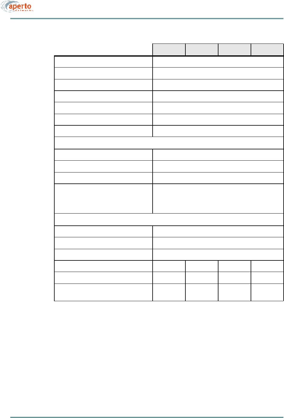
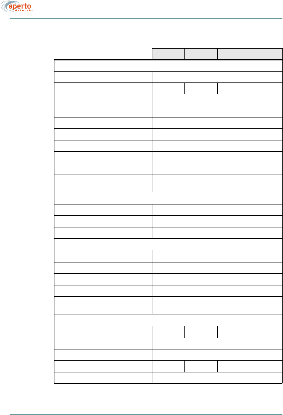
See Tables A-1 and A-2

CHAPTER A. SPECIFICATIONS
A–4070-20000340-01 Rev A
TableA-1 PacketWave Base Station Radios
2.5 GHz 3.5 GHz 5.3 GHz 5.8 GHz
General
Frequency Range 2500 to
2686 MHz 3400 to
3700 MHz 5250 to
5350 MHz 5725 to
5875 MHz
Channel Widths Supported From 1 to 6
MHz in 1
MHz steps
1.75, 3.5,
and 7.0 MHz From 1 to 6
MHz in 1
MHz steps
From 1 to 6
MHz in 1
MHz steps
Modulation QPSK and 16QAM, Adaptive
Duplexing Time Division Duplexing (TDD)
Transmitter
Maximum EIRP 33 dBm (per US FCC requirements, 18 dBi antenna
ACPR at Maximum EIRP
First Adjacent (3 MHz from F0)
Second Adjacent (6 MHz from F0)-37 dBc
-60 dBc
—TBD
TBD TBD
TBD
ACPR at Maximum EIRP (7 MHz spacing)
F0 + 5.6 MHz
F0 + 7.0 MHz
F0 + 14.0 MHz
—-32 dBc
-37 dBc
-50 dBc
— —
Transmitter Gain -10 to 25 dB -15 to 20 dB -15 to 20 dB -15 to 20 dB
Maximum Switching Time 2 µs, 10-90%
Maximum Group Delay 1.3 µs
Receiver
Maximum Receiver Noise Figure 5.0 dB 5.5 dB 6.5 dB 6.5 dB
Receiver Gain 30 ±tbd dB 30 ±3 dB 30 ±3 dB 30 ±3 dB
Minimum Receiver Input, IP3 -15 dBm -10 dBm -10 dBm -10 dBm
Maximum Switching Time 2 µs, 10 to 90%
Synthesizer
Maximum Phase Noise (10 kHz offset) -86 dBc/Hzt -83 dBc/Hzt -83 dBc/Hzt -83 dBc/Hzt
Reference Frequency 10 MHz ±500 Hz
Antenna Port
Connectors 4 female N-type
Signal Port
Connector Female F-type
A–5070-20000340-01 Rev A
CHAPTER A. SPECIFICATIONS
Impedance 75 ohms
10 MHz Reference Level 100 mVpp to 5 Vpp, sinusoidal
IF Signal 44 MHz
Maximum IF Signal Level 7 dBm
DC Voltage Range 10 to 20 V
Maximum Current Draw at +12 V 950 mA
Worst Case Return Loss -15 dB
Control Port
Connector RJ45 female
Maximum Data Rate 4 Mbps
Maximum CAT-5 Cable Length 150 ft
Radio Alarms Reported Transmitter Overpower Accuracy, ±1 dB
VCXO Lock
Synthesizer Lock
Undervoltage, less than 9.5 V
Environmental
Operating Temperature -22 to 140 °F (-30 to 60 °C)
Storage Temperature -40 to 257 °F (-40 to 125 °C
Relative Humidity 0 to 100%
W x H x D, without mounting bracket TBD TBD TBD TBD
Weigh TBD TBD TBD TBD
Regulatory Approvals FCC Part 15,
UL ETSI, CE FCC Part 15,
UL, U-NII FCC Part 15,
UL, U-NII
TableA-1 PacketWave Base Station Radios (Continued)
2.5 GHz 3.5 GHz 5.3 GHz 5.8 GHz
CHAPTER A. SPECIFICATIONS
A–6070-20000340-01 Rev A
TableA-2 PacketWave Base Station Antennas: 60º Sectors
2.5 GHz 3.5 GHz 5.3 GHz 5.8 GHz
General
Number of Antennas for Spacial Diversity 2
Minimum Gain 15 dBi 15 dBi 16 dBi 15 dBi
Maximum VSWR 2.0:1
Maximum Input Power 6 W
Polarization Dual Horizontal and Vertical
Minimum Cross-Polarization Isolation 20 dB
Minimum Front-to-Back Isolation 30 dB
Maximum Sidelobe Level -30 dB at ±90º
Maximum H-V/Diversity Switching Time 1 µs
3 dB Beamwidth: Azimuth (horizontal)
Elevation (vertical) 60º
9º with null fill
Connectors
Base Station Signal Female N-type
Base Station Control Female RJ45
Antenna 4 female N-type
Environmental
Operating Temperature -22 to 140 °F (-30 to 60 °C)
Storage Temperature -40 to 257 °F (-40 to 125 °C)
Wind, Operational 75 mph (120 km/hr)
Wind, Survival 125 mph (200 km/hr)
Relative Humidity 0 to 100%
Physical
W x H x D, without mounting bracket TBD TBD TBD TBD
Elevation Adjustment TBD
Mounting Pole Diameter 2 to 4.5 inches (5.1 to 11.4 cm)
Weight TBD TBD TBD TBD
Regulatory Approvals FCC Part 15, UL, CE