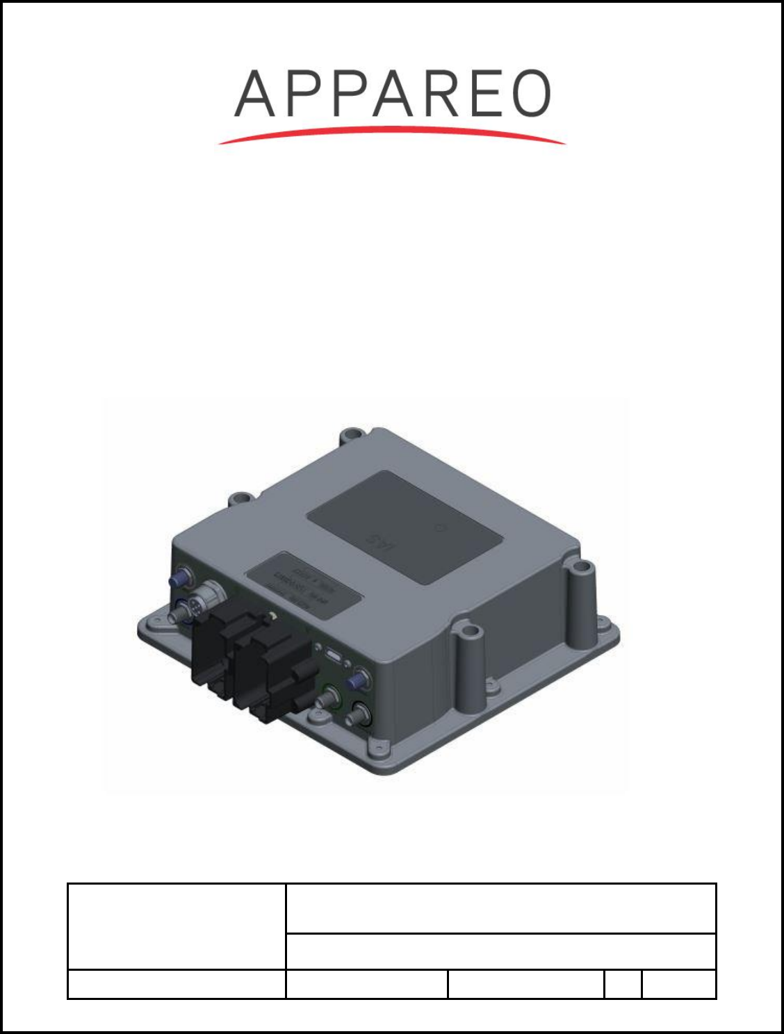
Appareo Systems 000034 Wireless embedded computer with Cellular/Satellite /WiFi/BT and M2M transmitter User Manual
Appareo Systems, LLC Wireless embedded computer with Cellular/Satellite /WiFi/BT and M2M transmitter
User Manual
This document and the information
contained herein are the property of
Appareo Systems, LLC and are
confidential. They may not be disseminated
or redistributed without the written
permission of Appareo Systems, LLC
APPAREO SYSTEMS, LLC
FARGO, NORTH DAKOTA 58102
Harvey Installation Manual
DOCUMENT NUMBER
600840-000041
Document Type
Manual
Last Revised
4/20/17
REV
1.0
Sheet
1 of 11
600840-000041 Harvey Installation Manual
Harvey, Gateway High Spec, GW 400, GW 410, and GW 411

600840-000041 Gateway Installation Manual
Rev: 1.0
Last Revised: 4/21/17
Document Number: 600840-000038
Page 2 of 11
Record of Revisions
Revision
Number
Change Description
Effective
Date
Inserted By
1.0
Initial draft
12/4/18
Lee Hinsz

600840-000041 Gateway Installation Manual
Rev: 1.0
Last Revised: 4/21/17
Document Number: 600840-000038
Page 3 of 11
Table of Contents
List of Figures ............................................................................................................................ 4
List of Tables ............................................................................................................................. 4
1. SYSTEM OVERVIEW .......................................................................................................... 5
2. PURPOSE ........................................................................................................................... 5
3. GENERAL INFORMATION .................................................................................................. 5
3.1. SPECIAL TOOLS REQUIRED ................................................................................. 5
3.2. INSTALLATION INSTRUCTIONS OVERVIEW ........................................................ 6
3.3. PARTS LIST FOR INSTALLATION .......................................................................... 6
3.4. HARDWARE COMPONENTS BACKGROUND ........................................................ 7
3.4.1. Electrical Characteristics ................................................................................... 7
3.4.2. Weight and Balance Information ........................................................................ 7
3.4.3. Equipment Dimensions ..................................................................................... 7
3.4.4. Conditions for operation .................................................................................... 7
4. CONFIGURATION ............................................................................................................... 8
4.1. Gateway System Separation Distances .................................................................... 8
4.2. Gateway System Separation Distance Illustration .................................................... 9
5. REgulatory Information ........................................................................................................10
5.1. Federal Communications Commission Notification to User .....................................10
5.2. industry Canada Notifications to User ......................................................................10

600840-000041 Gateway Installation Manual
Rev: 1.0
Last Revised: 4/21/17
Document Number: 600840-000038
Page 4 of 11
List of Figures
Figure 1 Separation Distance ..................................................................................................... 9
List of Tables
Table 1 System Component Minimum Spacing .......................................................................... 6
Table 2 Parts List for Installation ................................................................................................ 6
Table 3 Weight and Balance Information.................................................................................... 7
Table 4 Equipment Dimensions ................................................................................................. 7
Table 5 Separation Distance ...................................................................................................... 8

Installation Manual
Rev: 1.2
Last Revised: 3/22/16
Document Number: 600840-000038
Page 5 of 11
1. SYSTEM OVERVIEW
Harvey is an embedded computer that provides interfacing capability among a variety of wired
and wireless networks. It implements cellular designs, Bluetooth, WIFI, 433-MHz radio, and
Satcom interfaces. Hardline configuration include CAN, RS485, K-Line, RS232, and Broad
Reach Ethernet
2. PURPOSE
This Installation Manual is intended to inform installers and users of the proper placement,
configuration and distances between system components.
3. GENERAL INFORMATION
3.1. SPECIAL TOOLS REQUIRED
In addition to SAE standard and/or metric wrenches, sockets, and screw drivers, the following
tool are required:
1) Torque Wrench (in-lbs)
2) Wrench set
Installation Manual
Rev: 1.2
Last Revised: 3/22/16
Document Number: 600840-000038
Page 6 of 11
3.2. INSTALLATION INSTRUCTIONS OVERVIEW
System installation is accomplished in the following steps:
1) Installation of Gateway into the tractor cab headliner
a. Torque the antenna terminations to Gateway RF SMA connectors with a torque
spec of 7-10 in-lbs +/- 0.5 in-lbs. Mount the Gateway enclosure to the cab with ¼”
or 6-mm fasteners and a torque of 30 in-lbs.
2) Installation of Antennas
a. Find a location on the equipment such that the following distances are the
minimum spacing between system components.
Table 1 System Component Minimum Spacing
Operator
Gateway
Antenna Hub 1
(Recommended minimum
spacing between antenna
hubs is 7.5 cm)
30 cm ( in USA)
40 cm (in Canada)
20 cm
Antenna Hub 2
30 cm (USA)
40 cm (in Canada)
20 cm
Gateway
20 cm
N/A
b. Ensure the 433 MHZ antenna have a ground place of 300 x 300 mm for the
mounting.
c. Torque the antenna mounting nut (M14x1) to 30 +/- 0.5 in-lbs.
3.3. PARTS LIST FOR INSTALLATION
The following parts are required for the installation of Gateway.
Table 2 Parts List for Installation
Parts List for Installation
Item
Nomenclature
Part Number
QTY
1
Gateway
153010-000069 or
153010-000070
1
Installation Manual
Rev: 1.2
Last Revised: 3/22/16
Document Number: 600840-000038
Page 7 of 11
2
Antenna Hub 1
HCEL-S2-0164A-
00_Rev0 4G CELL-
433MHz-WLAN
1
3
Antenna Hub 2
HIRD-S2-0146A-
0_RevA Iridium-
GNSS-4G
1
3.4. HARDWARE COMPONENTS BACKGROUND
3.4.1. Electrical Characteristics
Input Power Requirements: 9-16 VDC
Current Draw at 14VDC: 250mA (nominal)
3.4.2. Weight and Balance Information
The total weight of the Gateway and antenna is listed below.
Table 3 Weight and Balance Information
Component
Weight (oz)
Weight (lbs)
Gateway
70.544
4.409
Antenna Hub 1 (HCEL-S2-0164A-01 )
26.624
1.664
Antenna Hub 2 (HIRD-S2-0146A-01)
26.624
1.664
3.4.3. Equipment Dimensions
Equipment dimensions are outlined in the table below for all required components in Gateway.
All figures given are representative of maximum equipment dimensions (where applicable).
Table 4 Equipment Dimensions
Component
Length
(mm)
Width
(mm)
Height
(mm)
Gateway
165
159
54
Antenna Hub 1 (HCEL-S2-0164A-01 )
124.3
80.3
80.3
Antenna Hub 2 (HIRD-S2-0146A-01)
124.3
80.3
80.3
3.4.4. Conditions for operation
IMPORTANT NOTICE!!!!
This device can be configured to transmit on the 433 MHz frequency following the requirements
of 15.231(a-d). This requirement is that the transmission must be used as a control signal. It
can include data transmission as well, or not, but in all cases it must be a control signal. Failure
to adhere to this requirement void’s the authority to operate the equipment.
Installation Manual
Rev: 1.2
Last Revised: 3/22/16
Document Number: 600840-000038
Page 8 of 11
4. CONFIGURATION
With equipment installed, final configuration must meet the minimum separation distance in
Table 5 and Section 4.2.
4.1. HARVEY SYSTEM SEPARATION DISTANCES
Operator
Gateway
Antenna Hub 1, 2
(Recommended minimum
spacing between antenna
hubs is 7.5 cm)
40 cm (USA)
40 cm (Canada)
20 cm
Harvey
20 cm
N/A
Table 5 Separation Distance
Installation Manual
Rev: 1.2
Last Revised: 3/22/16
Document Number: 600840-000038
Page 9 of 11
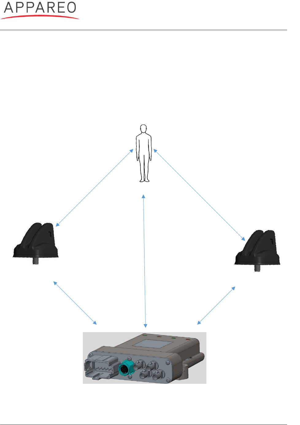
4.2. HARVEY SYSTEM SEPARATION DISTANCE ILLUSTRATION
Harvey and the following components must follow the distances in the following illustration to
comply with FCC part 1.310 and ISED RSS-102.
Note: To adhere with RF exposure requirement, the equipment is intended for PROFESSIONAL
INSTALLATION ONLY.
Operator
Antenna Hub 1
Antenna Hub 2
40 cm (USA)
40 cm (Canada)
20 cm
20 cm
20 cm
Figure 1 Separation Distance
40 cm (USA)
40 cm (Canada)
Gateway

Installation Manual
Rev: 1.2
Last Revised: 3/22/16
Document Number: 600840-000038
Page 10 of 11
5. REGULATORY INFORMATION
5.1. FEDERAL COMMUNICATIONS COMMISSION NOTIFICATION TO
USER
Harvey, Gateway High Spec, GW 400, GW 410, and GW 411
These devices comply with Part 15 of the Federal Communications Commission (FCC) Rules.
Operation is subject to the following two conditions: (1) These devices may not cause harmful
interference, and (2) these devices must accept any interference received, including
interference that may cause undesired operation.
These devices must be operated as supplied by Appareo Systems LLC. Any changes or
modifications made to these devices without the express written approval of Appareo Systems
LLC may void the user’s authority to operate these devices.
This equipment has been tested and found to comply with the limits for Class B digital devices,
pursuant to part 15 of the FCC Rules. These limits are designed to provide reasonable
protection against harmful interference in a residential installation. This equipment generates,
uses, and can radiate radio frequency energy and, if not installed and used in accordance with
the instructions, may cause harmful interference to radio communications. However, no
guarantee shall be made that interference will not occur in a particular installation. If this
equipment does cause harmful interference to radio or television reception, which can be
determined by turning the equipment off and on, the user is encouraged to try to correct the
interference by one or more of the following measures:
• Reorient or relocate the receiving antenna.
• Increase the separation between the equipment and receiver.
• Connect the equipment into an outlet on a circuit different from that to which the receiver is
connected.
• Consult the dealer or an experienced radio/TV technician for help.
5.2. INDUSTRY CANADA NOTIFICATIONS TO USER
Harvey, Gateway High Spec, GW 400, GW 410, and GW 411
English
These devices complies with Industry Canada licence-exempt RSS standard(s). Operation is
subject to the following two conditions: (1) this device may not cause interference, and (2) this
device must accept any interference, including interference that may cause undesired operation
of the device.
Under Industry Canada regulations, this radio transmitter may only operate using an antenna of
a type and maximum (or lesser) gain approved for the transmitter by Industry Canada. To
reduce potential radio interference to other users, the antenna type and its gain should be so
chosen that the equivalent isotropically radiated power (e.i.r.p.) is not more than that necessary
for successful communication.

Installation Manual
Rev: 1.2
Last Revised: 3/22/16
Document Number: 600840-000038
Page 11 of 11
French
Ces appareils sont conformes aux normes RSS sans licence d'Industrie Canada. Son
fonctionnement est soumis aux deux conditions suivantes: (1) cet appareil ne doit pas causer
d’interférences et (2) cet appareil doit accepter toute interférence, y compris les interférences
pouvant entraîner un fonctionnement non souhaité de l’appareil.
Selon les réglementations d'Industrie Canada, cet émetteur radio ne peut fonctionner qu'avec
une antenne d'un type et d'un gain maximal (ou inférieur) approuvé pour l'émetteur par Industrie
Canada. Pour réduire le risque de brouillage radioélectrique causé aux autres utilisateurs, le
type d’antenne et son gain doivent être choisis de manière à ce que la puissance rayonnée
isotrope équivalente (e.i.r.p.) ne soit pas supérieure à celle nécessaire au succès de la
communication.