Arcadyan Technology AR4505NW DIGITAL TRANSMISSION SYSTEM User Manual 3com
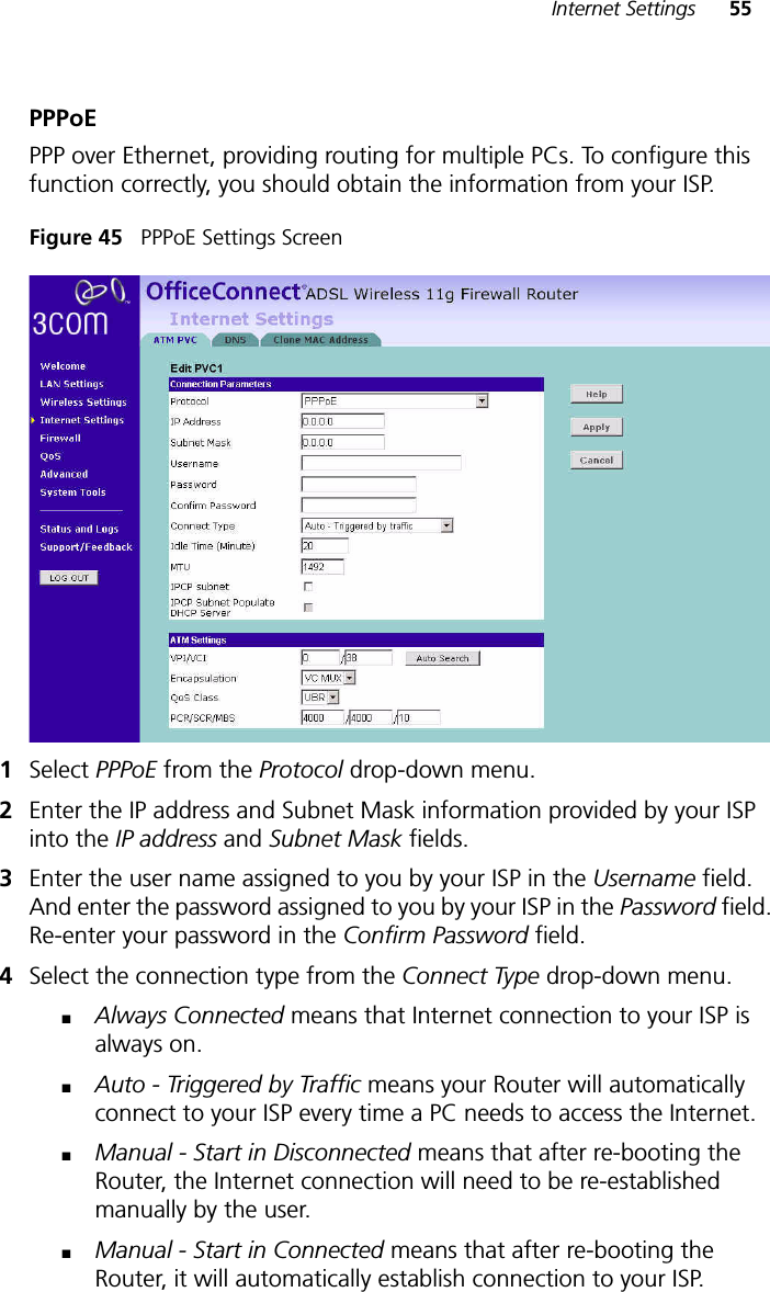
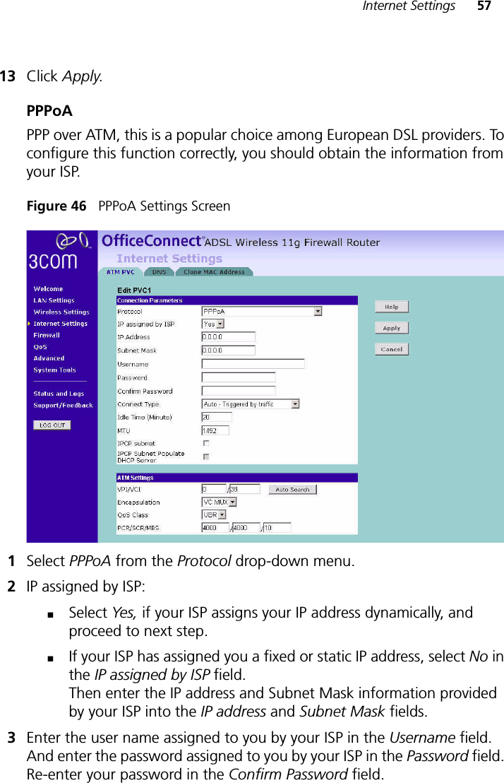
Arcadyan Technology Corporation DIGITAL TRANSMISSION SYSTEM 3com
Contents
- 1. USERS MANUAL 1 OF 4
- 2. USERS MANUAL 2 OF 4
- 3. USERS MANUAL 3 OF 4
- 4. USERS MANUAL 4 OF 4
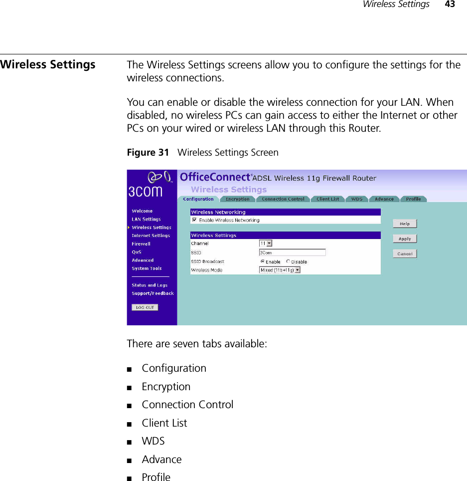
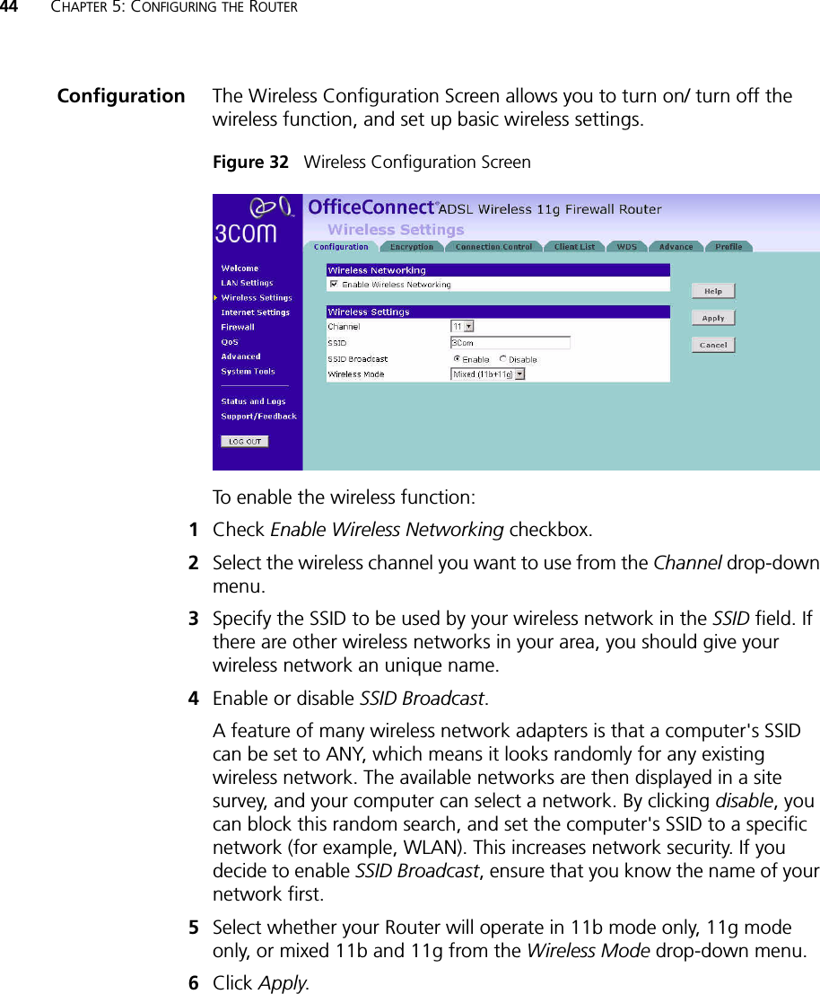
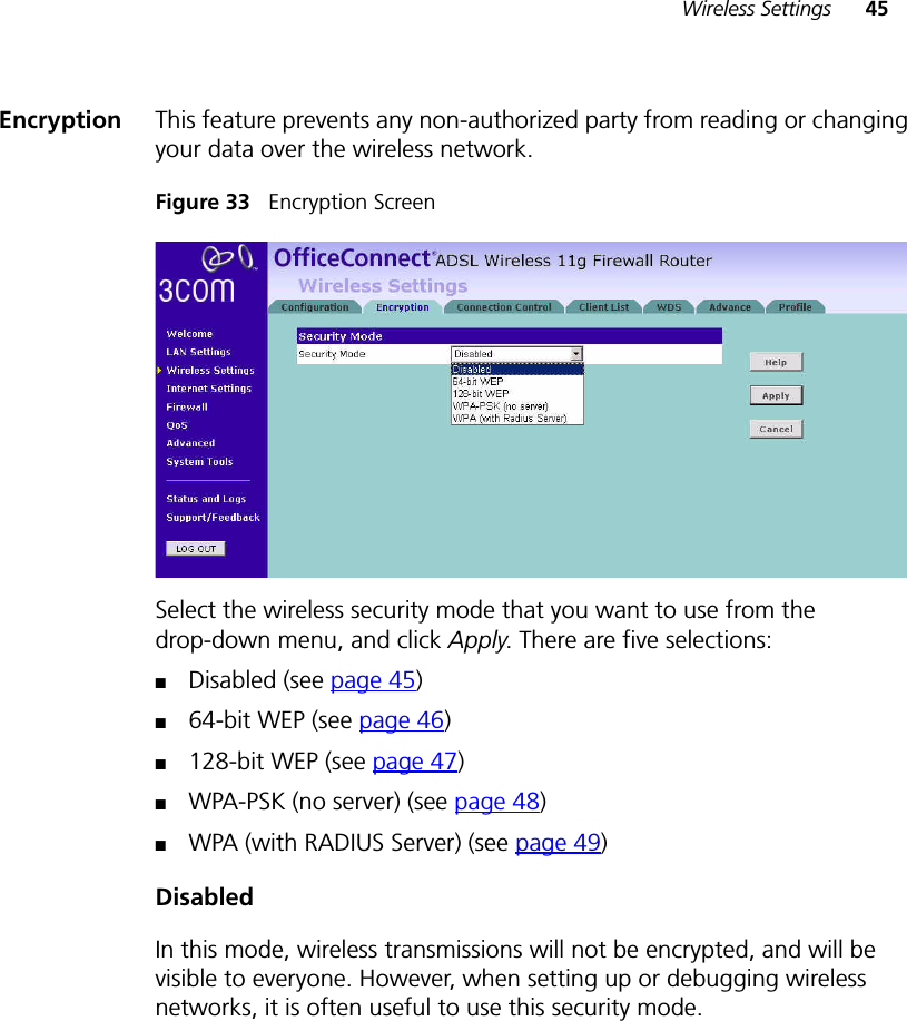
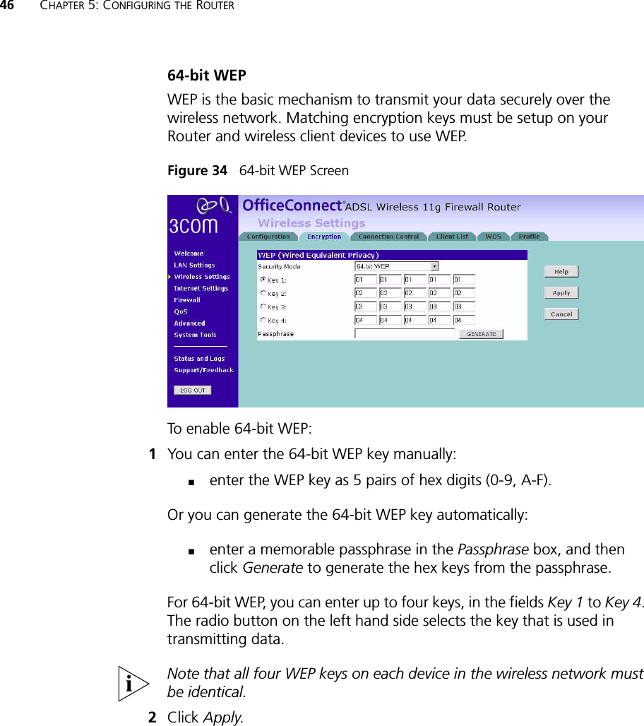
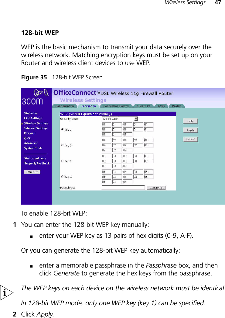
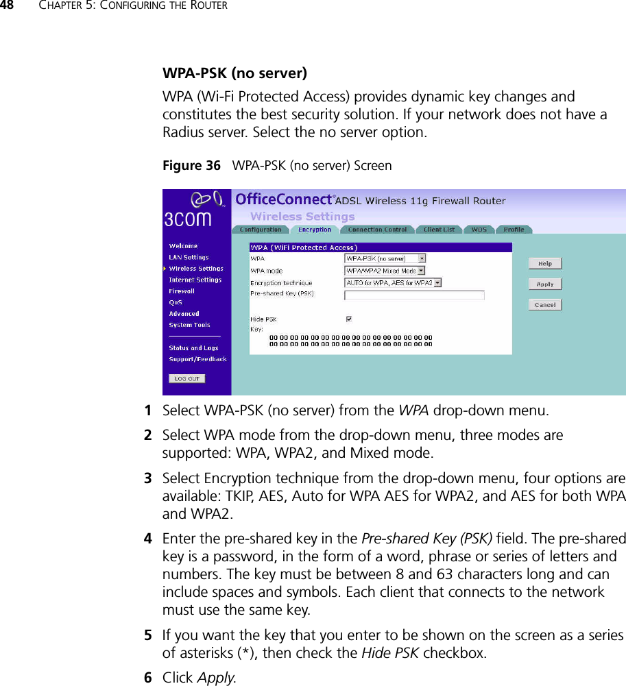
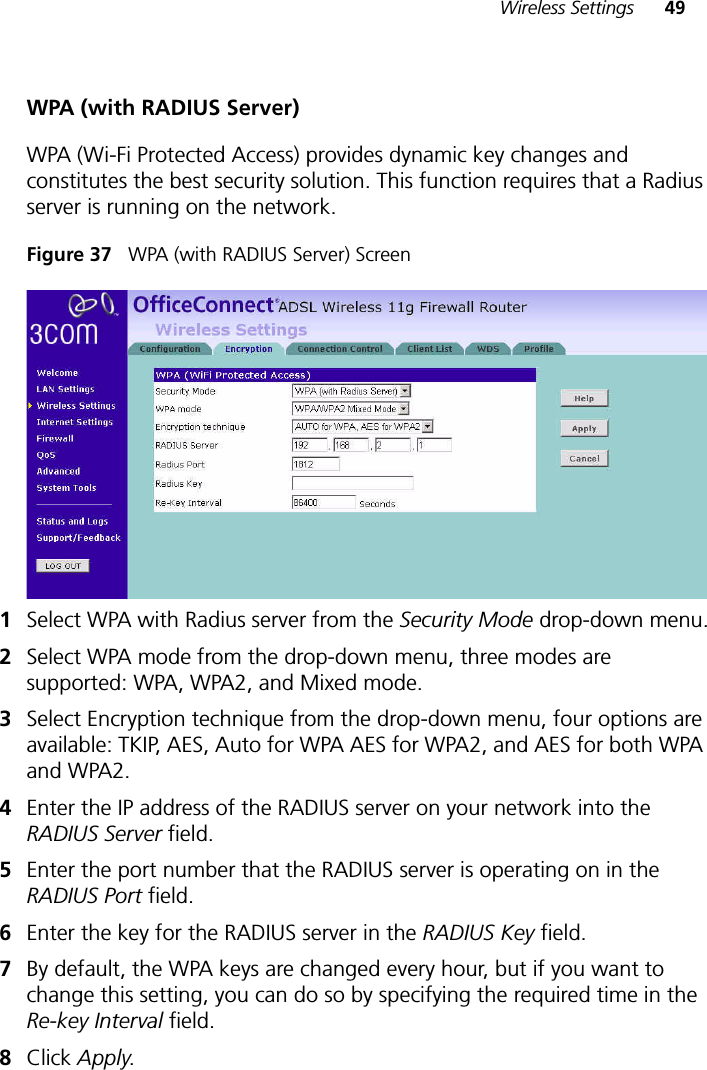
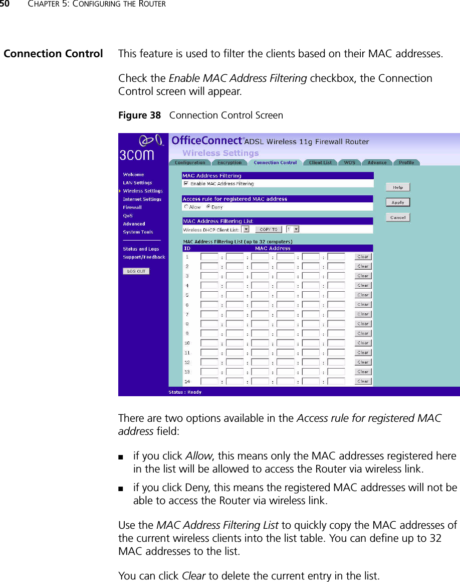
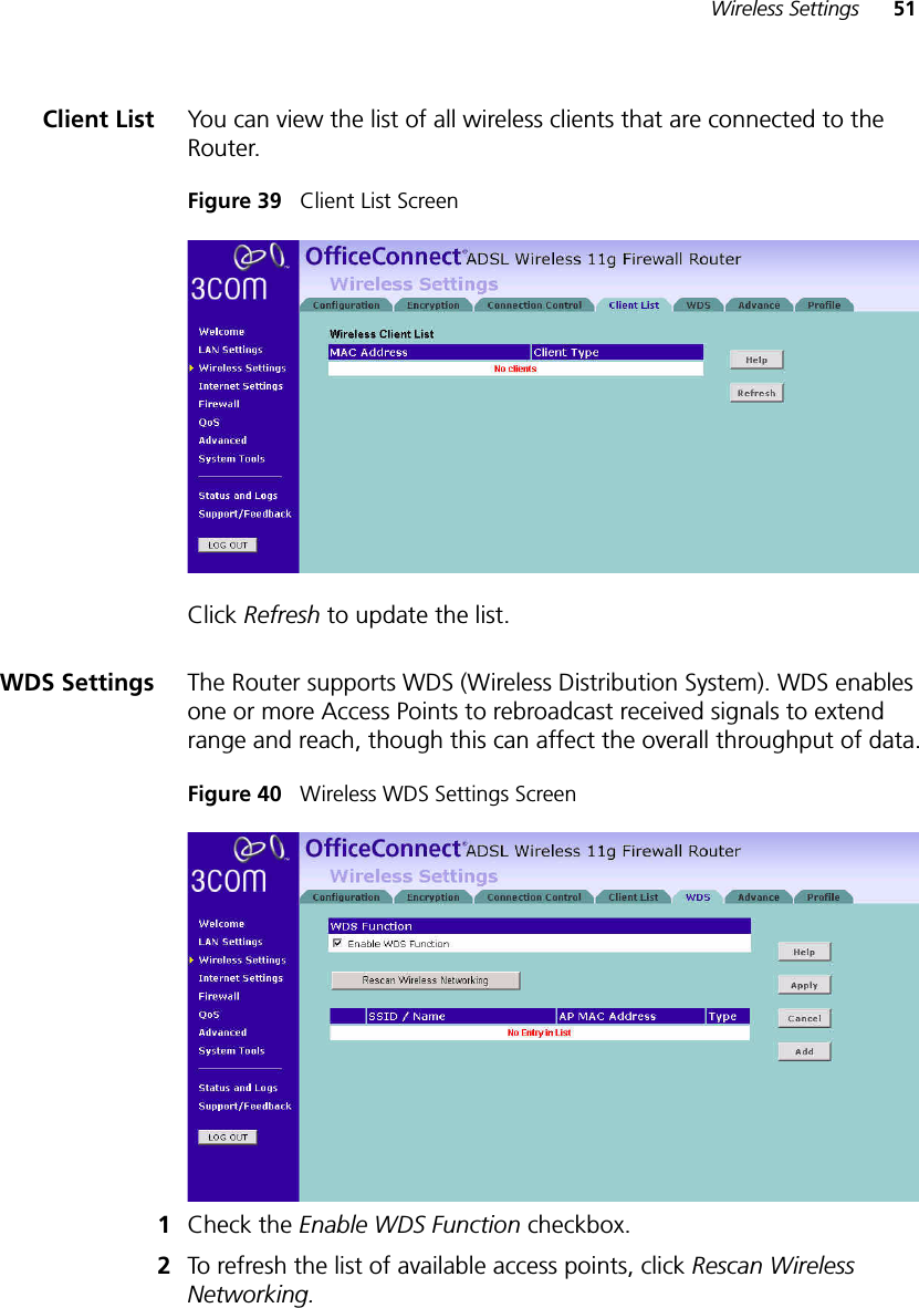
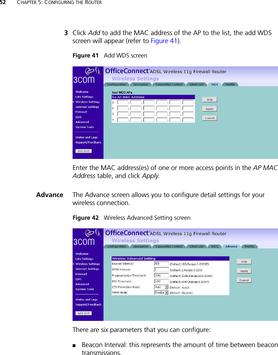
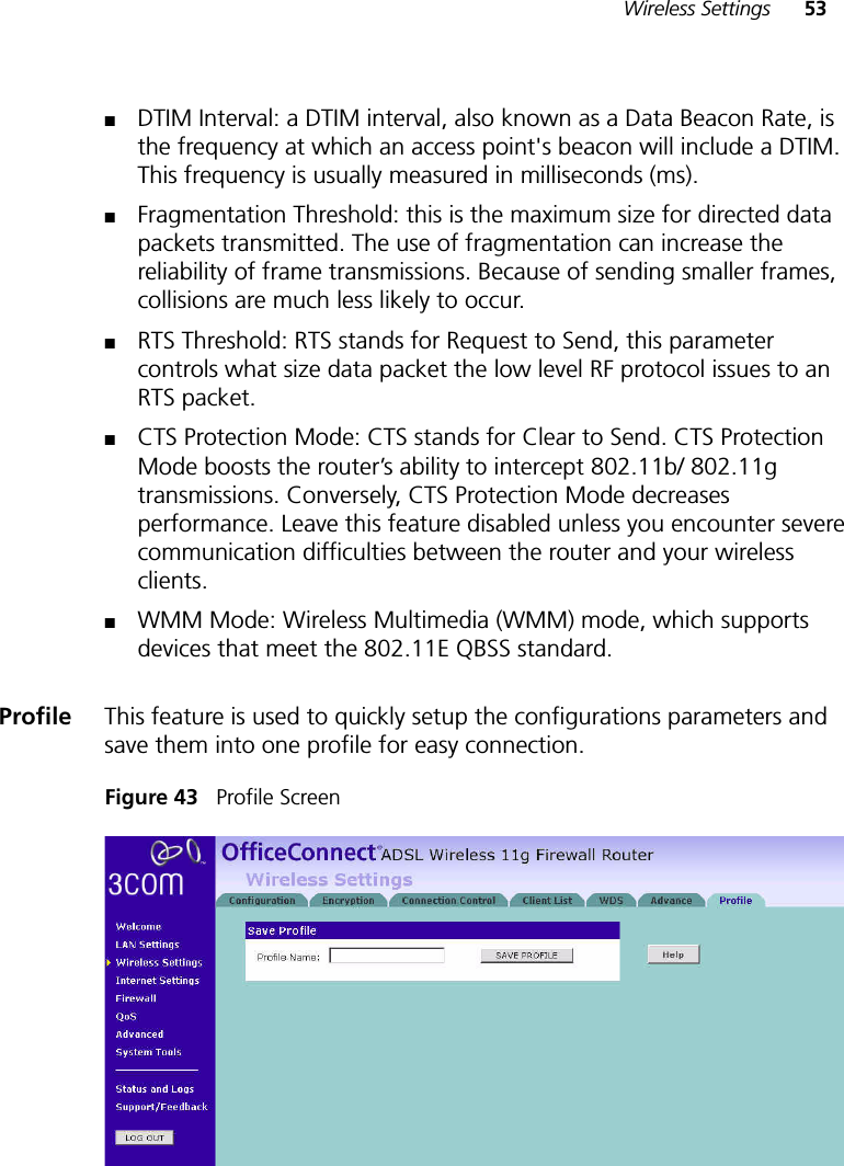
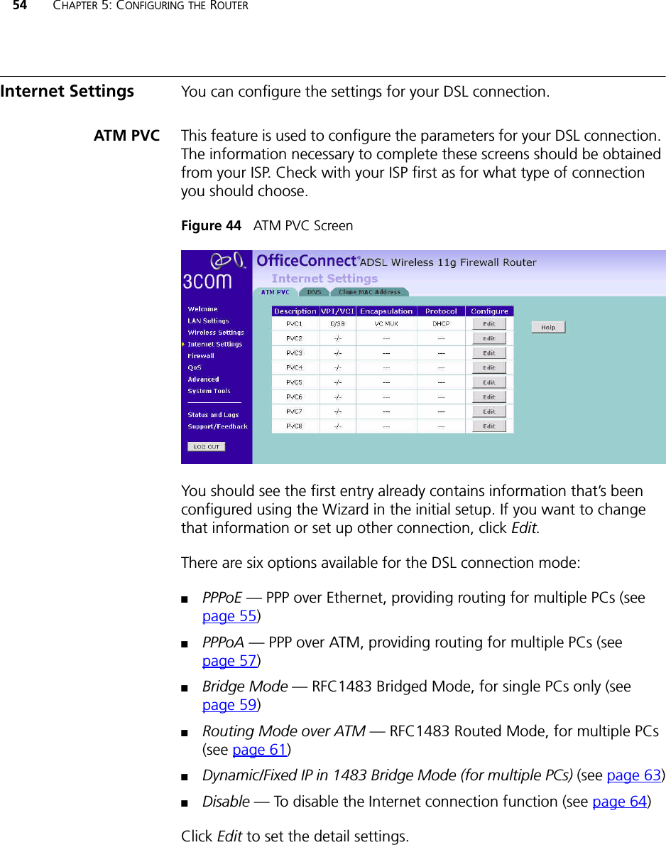
USERS MANUAL 2 OF 4