Arcadyan Technology AR4505NW DIGITAL TRANSMISSION SYSTEM User Manual 3com
Arcadyan Technology Corporation DIGITAL TRANSMISSION SYSTEM 3com
Contents
- 1. USERS MANUAL 1 OF 4
- 2. USERS MANUAL 2 OF 4
- 3. USERS MANUAL 3 OF 4
- 4. USERS MANUAL 4 OF 4
USERS MANUAL 2 OF 4
Accessing the Setup Wizard 35
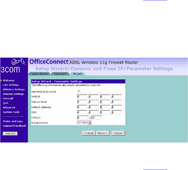
1Enter your Internet IP address in the WAN IP field.
2Enter the subnet mask in the Subnet Mask field.
3Enter the default gateway IP address in the Default Gateway field.
4Enter the DNS address in the DNS field.
5Enter your VPI and VCI information in the VPI/VCI fields.
6Select the encapsulation type (LLC or VC MUX) in the Encapsulation
drop-down menu. This information should be provided to you by your ISP.
7Check all of your settings, and then click Next.
The LAN Settings screen will then be displayed (refer to Figure 24).
Dynamic/Fixed IP in 1483 Bridge Mode (For Multiple PCs)
For bridge mode to work, you need to assign an IP address to the Router.
You can either configure the Router to obtain an IP address automatically
from a DHCP server or assign a fixed or static IP address to it.
Figure 23 Dynamic/Fixed IP for Bridge Mode Screen
To obtain an IP address automatically from a DHCP server:
Check the Get WAN IP By DCHP checkbox, and then click Next.
The LAN Settings screen will then be displayed (refer to Figure 24).
36 CHAPTER 4: RUNNING THE SETUP WIZARD
To assign a fixed IP address:
1Enter your Internet IP address in the WAN IP field.
2Enter the subnet mask in the Subnet Mask field.
3Enter the default gateway IP address in the Default Gateway field.
4Enter the DNS address in the DNS field.
5Enter your VPI and VCI information in the VPI/VCI text boxes.
6Select the encapsulation type (LLC or VC MUX) in the Encapsulation
drop-down menu. This information should be provided to you by your ISP.
7Check all of your settings, and then click Next.
The LAN Settings screen will then be displayed (refer to Figure 24).
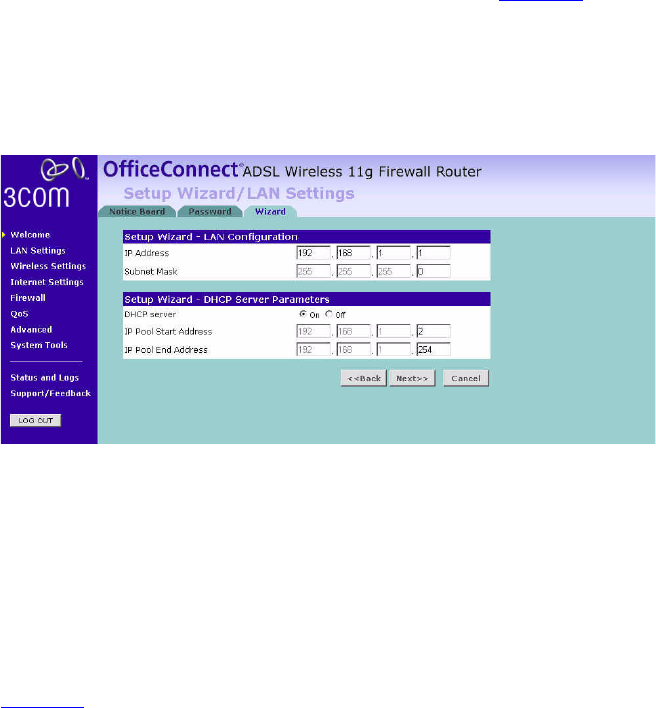
Setup Wizard - LAN
Settings
The LAN Settings screen allows you to set the default IP address and
DHCP client IP range for the Router.
Figure 24 The LAN Settings Screen
1To change the Router’s default IP address, enter the new IP address in the
IP Address field, and then enter the subnet mask in the Subnet Mask
field.
2Select the On/Off button to turn on/turn off the DHCP function in the
DHCP Server field.
3Enter the client IP address range in the IP Pool Start Address and IP Pool
End Address fields.
4Click Next. The Wireless Settings screen will be displayed (refer to
Figure 25).
Accessing the Setup Wizard 37
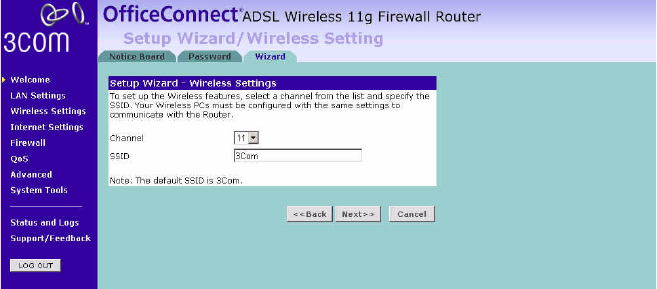
Setup Wizard -
Wireless Settings
The Wireless Settings screen allows you to set up the SSID and radio
channel used for the wireless connection.
Figure 25 Wireless Settings Screen
1Select the channel you want to use from the Channel drop-down menu.
2Specify the SSID to be used by your Wireless Network in the SSID field. If
there are other wireless networks in your area, you should give your
wireless network an unique name.
38 CHAPTER 4: RUNNING THE SETUP WIZARD
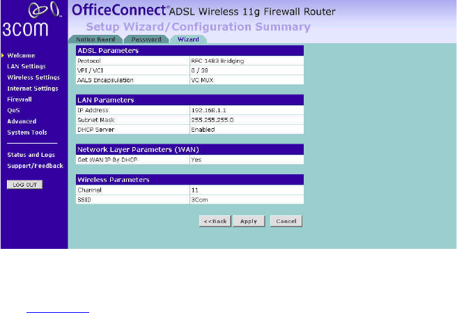
Setup Wizard -
Configuration
Summary
When you have completed the Setup Wizard, a configuration summary
will appear. Verify the configuration information of the Router and then
click Apply to save your settings. 3Com recommends that you print out
this page for your records.
Figure 26 Configuration Summary Screen
Your Router is now configured and ready for use.
See Chapter 5 for a detailed description of the Router configuration.
5CONFIGURING THE ROUTER
Navigating
Through the Router
Configuration
Pages
This chapter describes all the screens available through the Router
configuration pages, and is provided as a reference. To get to the
configuration pages, enter the Router’s default IP in the location bar of
your browser. The default IP is http://192.168.1.1.
However, if you changed the Router LAN IP address during initial
configuration, use the new IP address instead. Enter your password to
login to the management interface. (The default password is admin).
Main Menu The main menu is located on the left side, as shown in Figure 27. When
you click on an item from the main menu, that page will appear in the
main part of the screen.
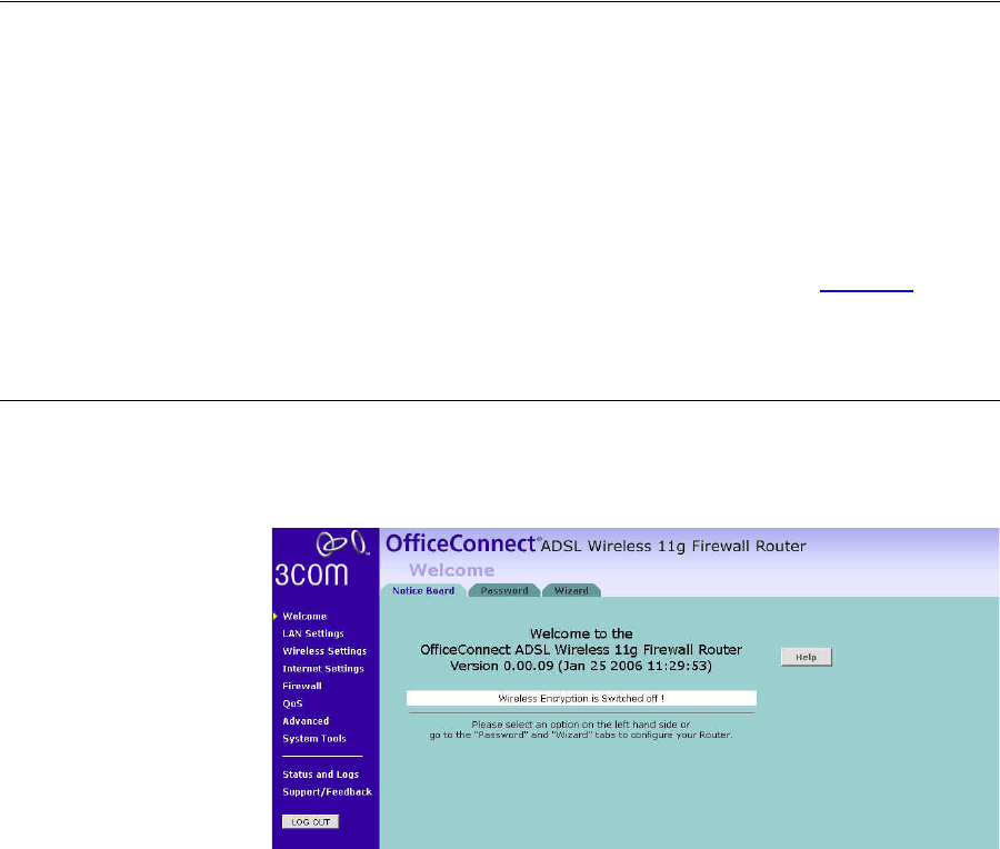
Welcome Screen The Welcome screen shows the current software information.
Status Figure 27 Welcome Screen
40 CHAPTER 5: CONFIGURING THE ROUTER
LAN Settings Your Router is equipped with a DHCP server that will automatically assign
IP addresses to each computer on your network. The factory default
settings for the DHCP server will work with most applications. If you need
to make changes to the settings, you can do so.
The LAN settings screen allows you to:
■Change the default IP address of the Router. The default IP is
192.168.1.1
■Change the Subnet Mask. The default setting is 255.255.255.0
■Enable/Disable the DHCP Server Function. The default is ON (Enabled).
■Specify the Starting and Ending IP Pool address. The default is
Starting: 2 / Ending: 254.
■Specify the IP address Lease Time. The default is Half day.
■Specify a local Domain Name. The default is NONE.
The Router will also provide a list of all client computers connected to the
Router.
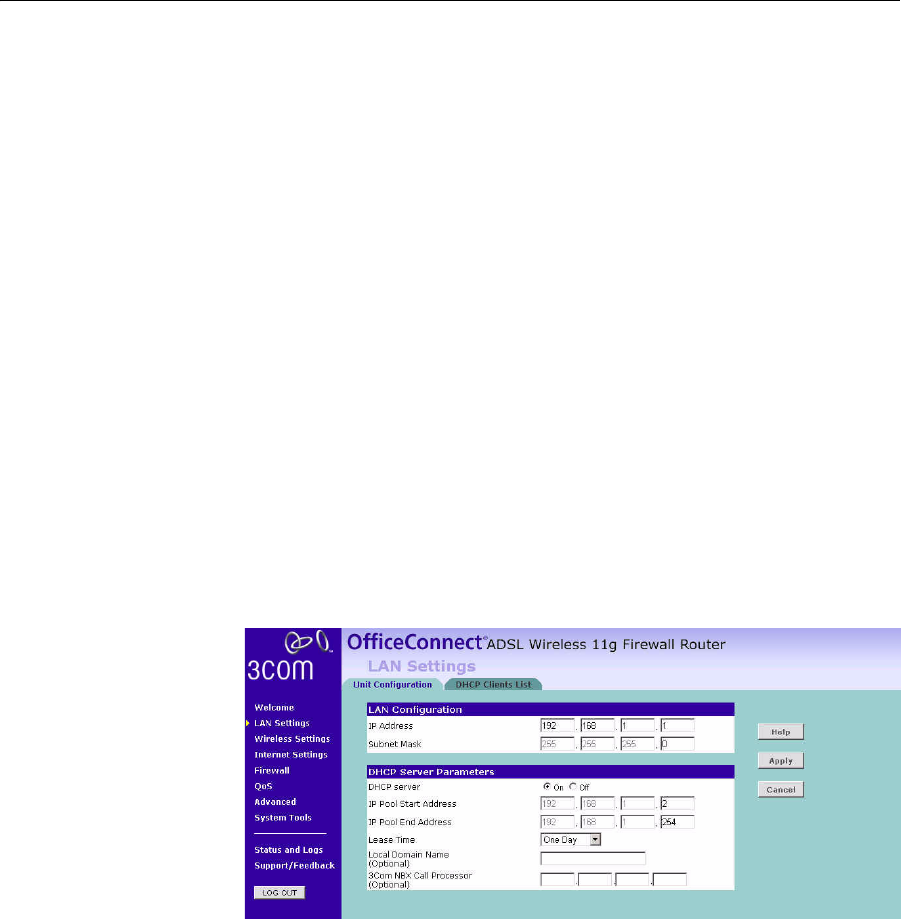
LAN Settings The LAN Settings screen is used to specify the LAN IP address of your
Router, and to configure the DHCP server.
Figure 28 LAN Settings Screen
1Enter the Router’s IP Address and Subnet Mask in the appropriate fields.
The default IP address is 192.168.1.1.
2If you want to use the Router as a DHCP Server, select On in the DHCP
Server field.
LAN Settings 41
3Enter the IP address range in the IP Pool Start Address and IP Pool End
Address fields.
4Specify the DHCP Lease time by selecting the required value from the
Lease Time drop-down menu. The lease time is the length of time the
DHCP server will reserve the IP address for each computer.
5Specify the Local Domain Name for your network (this step is optional).
6Enter the IP address of the NBX Call Processor in the 3Com NBX Call
Processor field (this step is optional).
7Check all of your settings, and then click Apply.
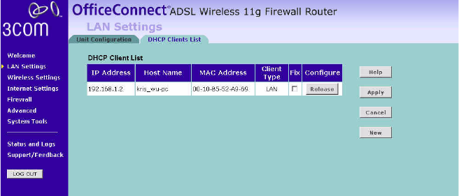
DHCP Clients List The DHCP Clients List provides details on the devices that have received IP
addresses from the Router. The list is only created when the Router is set
up as a DHCP server. The maximum number of 253 clients can be
connected to the Router.
Figure 29 DHCP Clients List Screen
For each device that is connected to the LAN, the following information is
displayed:
■IP address — The Internet Protocol (IP) address issued to the client
machine.
■Host Name — The client machine’s host name, if configured.
■MAC Address — The Media Access Control (MAC) address of the
client’s network card.
■Client Type — Whether the client is connected to the Router by wired
or wireless connection.
42 CHAPTER 5: CONFIGURING THE ROUTER
■Check the Fix checkbox to permanently fix the IP address.
■Click Release to release the displayed IP address.
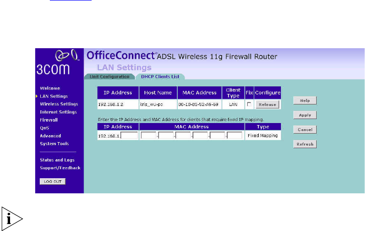
■Click New to allocate an IP address to a MAC address (refer to
Figure 30). Enter the required details and click Apply to save your
settings.
Figure 30 Fixed Mapping Clients List Screen
The DHCP server will give out addresses to both wired and wireless
clients.
Wireless Settings 43
Wireless Settings The Wireless Settings screens allow you to configure the settings for the
wireless connections.
You can enable or disable the wireless connection for your LAN. When
disabled, no wireless PCs can gain access to either the Internet or other
PCs on your wired or wireless LAN through this Router.
Figure 31 Wireless Settings Screen
There are seven tabs available:
■Configuration
■Encryption
■Connection Control
■Client List
■WDS
■Advance
■Profile
44 CHAPTER 5: CONFIGURING THE ROUTER
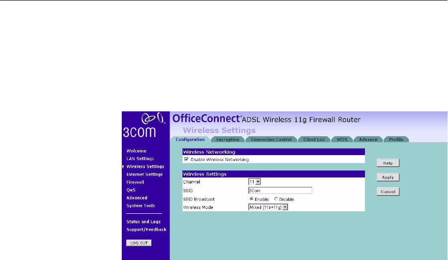
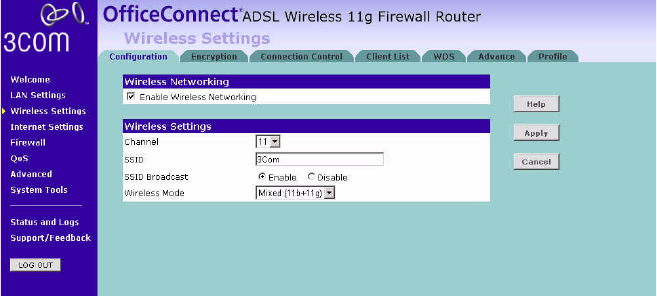
Configuration The Wireless Configuration Screen allows you to turn on/ turn off the
wireless function, and set up basic wireless settings.
Figure 32 Wireless Configuration Screen
To enable the wireless function:
1Check Enable Wireless Networking checkbox.
2Select the wireless channel you want to use from the Channel drop-down
menu.
3Specify the SSID to be used by your wireless network in the SSID field. If
there are other wireless networks in your area, you should give your
wireless network an unique name.
4Enable or disable SSID Broadcast.
A feature of many wireless network adapters is that a computer's SSID
can be set to ANY, which means it looks randomly for any existing
wireless network. The available networks are then displayed in a site
survey, and your computer can select a network. By clicking disable, you
can block this random search, and set the computer's SSID to a specific
network (for example, WLAN). This increases network security. If you
decide to enable SSID Broadcast, ensure that you know the name of your
network first.
5Select whether your Router will operate in 11b mode only, 11g mode
only, or mixed 11b and 11g from the Wireless Mode drop-down menu.
6Click Apply.
Wireless Settings 45
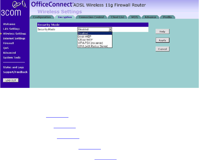
Encryption This feature prevents any non-authorized party from reading or changing
your data over the wireless network.
Figure 33 Encryption Screen
Select the wireless security mode that you want to use from the
drop-down menu, and click Apply. There are five selections:
■Disabled (see page 45)
■64-bit WEP (see page 46)
■128-bit WEP (see page 47)
■WPA-PSK (no server) (see page 48)
■WPA (with RADIUS Server) (see page 49)
Disabled
In this mode, wireless transmissions will not be encrypted, and will be
visible to everyone. However, when setting up or debugging wireless
networks, it is often useful to use this security mode.
46 CHAPTER 5: CONFIGURING THE ROUTER
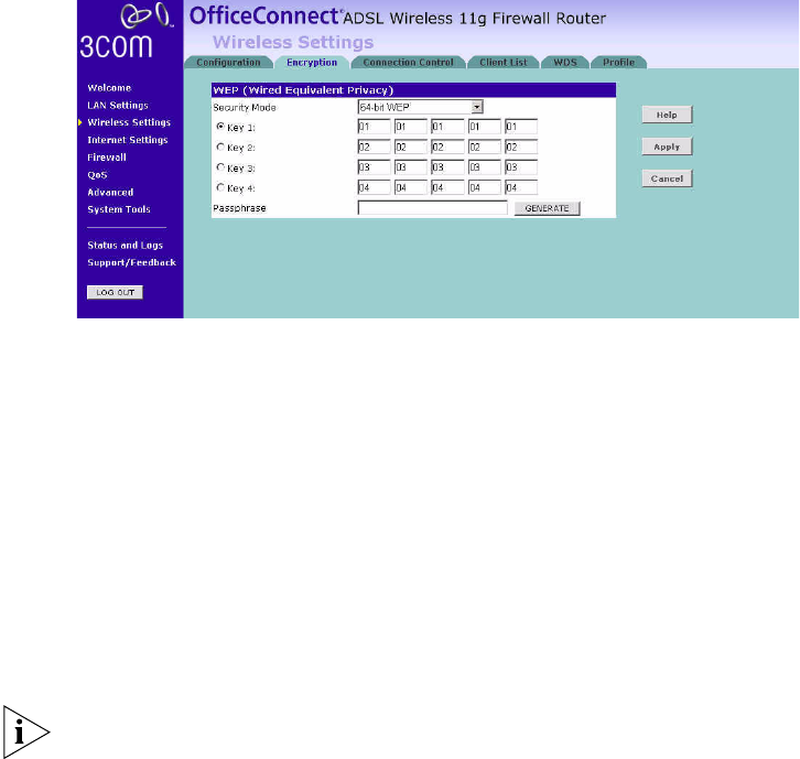
64-bit WEP
WEP is the basic mechanism to transmit your data securely over the
wireless network. Matching encryption keys must be setup on your
Router and wireless client devices to use WEP.
Figure 34 64-bit WEP Screen
To enable 64-bit WEP:
1You can enter the 64-bit WEP key manually:
■enter the WEP key as 5 pairs of hex digits (0-9, A-F).
Or you can generate the 64-bit WEP key automatically:
■enter a memorable passphrase in the Passphrase box, and then
click Generate to generate the hex keys from the passphrase.
For 64-bit WEP, you can enter up to four keys, in the fields Key 1 to Key 4.
The radio button on the left hand side selects the key that is used in
transmitting data.
Note that all four WEP keys on each device in the wireless network must
be identical.
2Click Apply.
Wireless Settings 47
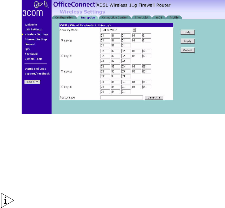
128-bit WEP
WEP is the basic mechanism to transmit your data securely over the
wireless network. Matching encryption keys must be set up on your
Router and wireless client devices to use WEP.
Figure 35 128-bit WEP Screen
To enable 128-bit WEP:
1You can enter the 128-bit WEP key manually:
■enter your WEP key as 13 pairs of hex digits (0-9, A-F).
Or you can generate the 128-bit WEP key automatically:
■enter a memorable passphrase in the Passphrase box, and then
click Generate to generate the hex keys from the passphrase.
The WEP keys on each device on the wireless network must be identical.
In 128-bit WEP mode, only one WEP key (key 1) can be specified.
2Click Apply.
48 CHAPTER 5: CONFIGURING THE ROUTER
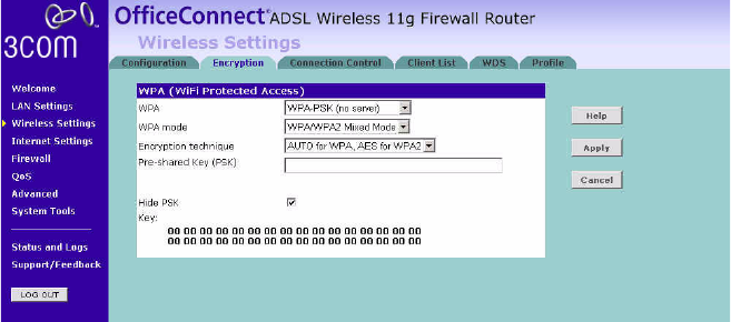
WPA-PSK (no server)
WPA (Wi-Fi Protected Access) provides dynamic key changes and
constitutes the best security solution. If your network does not have a
Radius server. Select the no server option.
Figure 36 WPA-PSK (no server) Screen
1Select WPA-PSK (no server) from the WPA drop-down menu.
2Select WPA mode from the drop-down menu, three modes are
supported: WPA, WPA2, and Mixed mode.
3Select Encryption technique from the drop-down menu, four options are
available: TKIP, AES, Auto for WPA AES for WPA2, and AES for both WPA
and WPA2.
4Enter the pre-shared key in the Pre-shared Key (PSK) field. The pre-shared
key is a password, in the form of a word, phrase or series of letters and
numbers. The key must be between 8 and 63 characters long and can
include spaces and symbols. Each client that connects to the network
must use the same key.
5If you want the key that you enter to be shown on the screen as a series
of asterisks (*), then check the Hide PSK checkbox.
6Click Apply.
Wireless Settings 49
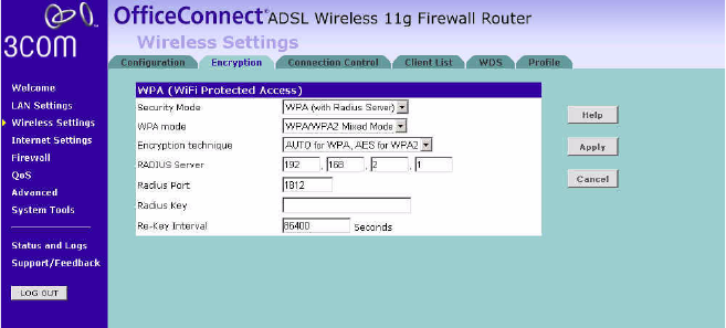
WPA (with RADIUS Server)
WPA (Wi-Fi Protected Access) provides dynamic key changes and
constitutes the best security solution. This function requires that a Radius
server is running on the network.
Figure 37 WPA (with RADIUS Server) Screen
1Select WPA with Radius server from the Security Mode drop-down menu.
2Select WPA mode from the drop-down menu, three modes are
supported: WPA, WPA2, and Mixed mode.
3Select Encryption technique from the drop-down menu, four options are
available: TKIP, AES, Auto for WPA AES for WPA2, and AES for both WPA
and WPA2.
4Enter the IP address of the RADIUS server on your network into the
RADIUS Server field.
5Enter the port number that the RADIUS server is operating on in the
RADIUS Port field.
6Enter the key for the RADIUS server in the RADIUS Key field.
7By default, the WPA keys are changed every hour, but if you want to
change this setting, you can do so by specifying the required time in the
Re-key Interval field.
8Click Apply.
50 CHAPTER 5: CONFIGURING THE ROUTER
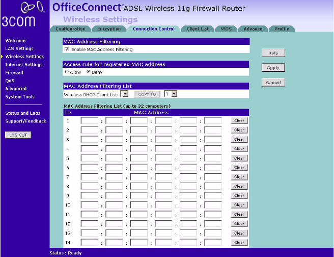
Connection Control This feature is used to filter the clients based on their MAC addresses.
Check the Enable MAC Address Filtering checkbox, the Connection
Control screen will appear.
Figure 38 Connection Control Screen
There are two options available in the Access rule for registered MAC
address field:
■if you click Allow, this means only the MAC addresses registered here
in the list will be allowed to access the Router via wireless link.
■if you click Deny, this means the registered MAC addresses will not be
able to access the Router via wireless link.
Use the MAC Address Filtering List to quickly copy the MAC addresses of
the current wireless clients into the list table. You can define up to 32
MAC addresses to the list.
You can click Clear to delete the current entry in the list.
Wireless Settings 51
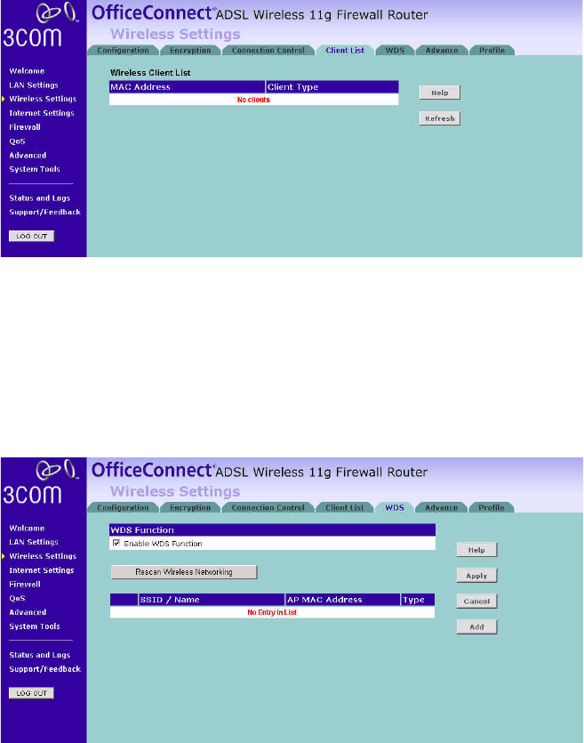
Client List You can view the list of all wireless clients that are connected to the
Router.
Figure 39 Client List Screen
Click Refresh to update the list.
WDS Settings The Router supports WDS (Wireless Distribution System). WDS enables
one or more Access Points to rebroadcast received signals to extend
range and reach, though this can affect the overall throughput of data.
Figure 40 Wireless WDS Settings Screen
1Check the Enable WDS Function checkbox.
2To refresh the list of available access points, click Rescan Wireless
Networking.
52 CHAPTER 5: CONFIGURING THE ROUTER
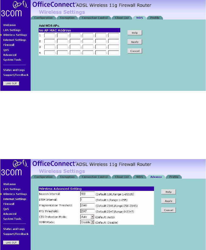
3Click Add to add the MAC address of the AP to the list, the add WDS
screen will appear (refer to Figure 41).
Figure 41 Add WDS screen
Enter the MAC address(es) of one or more access points in the AP MAC
Address table, and click Apply.
Advance The Advance screen allows you to configure detail settings for your
wireless connection.
Figure 42 Wireless Advanced Setting screen
There are six parameters that you can configure:
■Beacon Interval: this represents the amount of time between beacon
transmissions.
Wireless Settings 53
■DTIM Interval: a DTIM interval, also known as a Data Beacon Rate, is
the frequency at which an access point's beacon will include a DTIM.
This frequency is usually measured in milliseconds (ms).
■Fragmentation Threshold: this is the maximum size for directed data
packets transmitted. The use of fragmentation can increase the
reliability of frame transmissions. Because of sending smaller frames,
collisions are much less likely to occur.
■RTS Threshold: RTS stands for Request to Send, this parameter
controls what size data packet the low level RF protocol issues to an
RTS packet.
■CTS Protection Mode: CTS stands for Clear to Send. CTS Protection
Mode boosts the router’s ability to intercept 802.11b/ 802.11g
transmissions. Conversely, CTS Protection Mode decreases
performance. Leave this feature disabled unless you encounter severe
communication difficulties between the router and your wireless
clients.
■WMM Mode: Wireless Multimedia (WMM) mode, which supports
devices that meet the 802.11E QBSS standard.
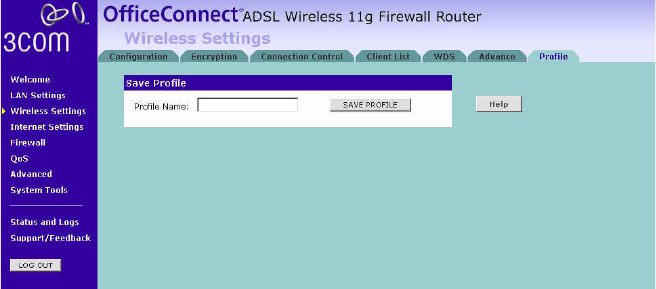
Profile This feature is used to quickly setup the configurations parameters and
save them into one profile for easy connection.
Figure 43 Profile Screen
54 CHAPTER 5: CONFIGURING THE ROUTER
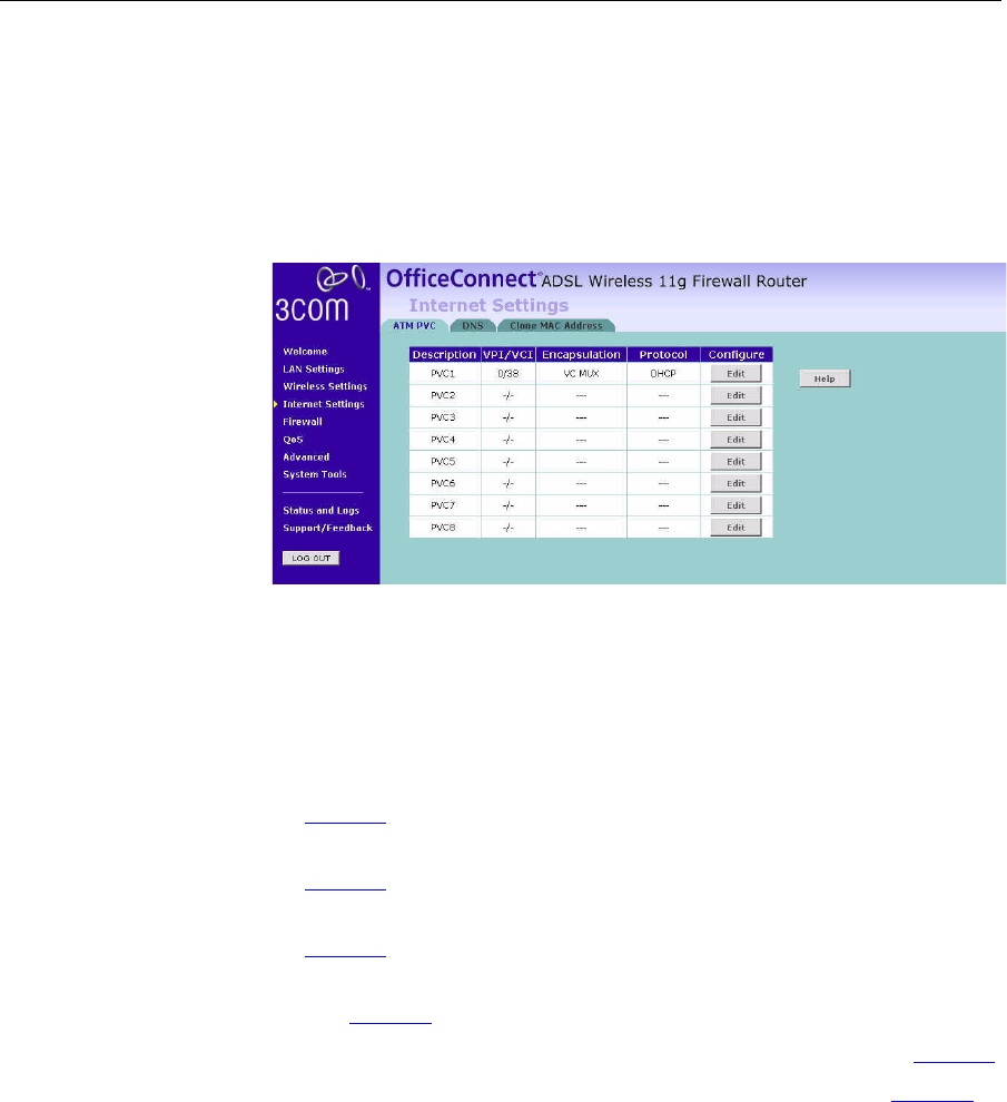
Internet Settings You can configure the settings for your DSL connection.
ATM PVC This feature is used to configure the parameters for your DSL connection.
The information necessary to complete these screens should be obtained
from your ISP. Check with your ISP first as for what type of connection
you should choose.
Figure 44 ATM PVC Screen
You should see the first entry already contains information that’s been
configured using the Wizard in the initial setup. If you want to change
that information or set up other connection, click Edit.
There are six options available for the DSL connection mode:
■PPPoE — PPP over Ethernet, providing routing for multiple PCs (see
page 55)
■PPPoA — PPP over ATM, providing routing for multiple PCs (see
page 57)
■Bridge Mode — RFC1483 Bridged Mode, for single PCs only (see
page 59)
■Routing Mode over ATM — RFC1483 Routed Mode, for multiple PCs
(see page 61)
■Dynamic/Fixed IP in 1483 Bridge Mode (for multiple PCs) (see page 63)
■Disable — To disable the Internet connection function (see page 64)
Click Edit to set the detail settings.
Internet Settings 55
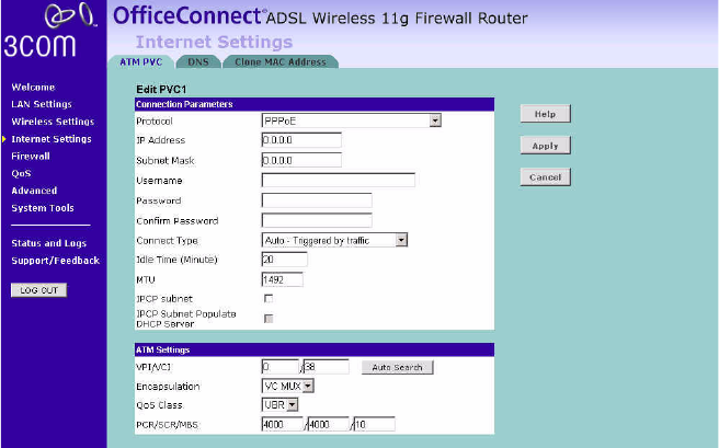
PPPoE
PPP over Ethernet, providing routing for multiple PCs. To configure this
function correctly, you should obtain the information from your ISP.
Figure 45 PPPoE Settings Screen
1Select PPPoE from the Protocol drop-down menu.
2Enter the IP address and Subnet Mask information provided by your ISP
into the IP address and Subnet Mask fields.
3Enter the user name assigned to you by your ISP in the Username field.
And enter the password assigned to you by your ISP in the Password field.
Re-enter your password in the Confirm Password field.
4Select the connection type from the Connect Type drop-down menu.
■Always Connected means that Internet connection to your ISP is
always on.
■Auto - Triggered by Traffic means your Router will automatically
connect to your ISP every time a PC needs to access the Internet.
■Manual - Start in Disconnected means that after re-booting the
Router, the Internet connection will need to be re-established
manually by the user.
■Manual - Start in Connected means that after re-booting the
Router, it will automatically establish connection to your ISP.
56 CHAPTER 5: CONFIGURING THE ROUTER
■Manual - Start in Last State means that after re-booting the Router,
the Internet connection will stay in the previous condition before
the reboot.
5If you want your Router to automatically disconnect from the Internet
after a period of inactivity, specify a time in the Idle Time (Minutes) field.
(Enter a value of 0 to disable this timeout).
6Enter the MTU value supplied by your ISP. If you do not know this, leave it
at the default value.
7The Router supports the IP Control Protocol (IPCP) Subnet Mask Support
feature, check the IPCP subnet checkbox to enable it.
8To use the IPCP Subnet Mask Support for the DHCP clients, check the
IPCP Subnet Populate DHCP Server checkbox.
9Enter the VPI and VCI values provided by your ISP in the VPI and VCI
fields. You can click Auto Search to automatically find out this
information.
10 Select the encapsulation type (LLC or VC MUX) in the Encapsulation field.
This information should be provided to you by your ISP.
11 Select the type of Quality of Service (CBR, UBR or VBR) in the QoS field.
■CBR (constant bit rate): the CBR service class is intended for
real-time applications, for example, those requiring tightly
constrained delay and delay variation, such as voice and video
applications. The consistent availability of a fixed quantity of
bandwidth is considered appropriate for CBR service.
■VBR (variable bit rate): QoS class defined by the ATM Forum for
ATM networks. VBR is subdivided into a real time (RT) class and
non-real time (NRT) class. VBR (RT) is used for connections in which
there is a fixed timing relationship between samples. VBR (NRT) is
used for connections in which there is no fixed timing relationship
between samples, but that still need a guaranteed QoS. Compare
with ABR, CBR, and UBR.
■UBR (unspecified bit rate): the UBR service class is intended for
delay-tolerant or non-real-time applications, for example, those
which do not require tightly constrained delay and delay variation,
such as traditional computer communications applications. The
UBR service may be considered as "best effort service".
12 Enter the PCR/SCR/MBS values. This information should be provided to
you by your ISP.
Internet Settings 57
13 Click Apply.
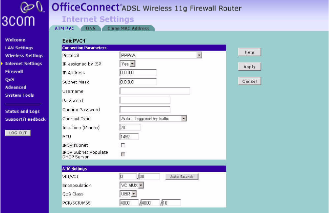
PPPoA
PPP over ATM, this is a popular choice among European DSL providers. To
configure this function correctly, you should obtain the information from
your ISP.
Figure 46 PPPoA Settings Screen
1Select PPPoA from the Protocol drop-down menu.
2IP assigned by ISP:
■Select Yes, if your ISP assigns your IP address dynamically, and
proceed to next step.
■If your ISP has assigned you a fixed or static IP address, select No in
the IP assigned by ISP field.
Then enter the IP address and Subnet Mask information provided
by your ISP into the IP address and Subnet Mask fields.
3Enter the user name assigned to you by your ISP in the Username field.
And enter the password assigned to you by your ISP in the Password field.
Re-enter your password in the Confirm Password field.
58 CHAPTER 5: CONFIGURING THE ROUTER
4Select the connection type from the Connect Type drop-down menu.
■Always Connected means that Internet connection to your ISP is
always on.
■Auto - Triggered by Traffic means your Router will automatically
connect to your ISP every time a PC needs to access the Internet.
■Manual - Start in Disconnected means that after re-booting the
Router, the Internet connection will need to be re-established
manually by the user.
■Manual - Start in Connected means that after re-booting the
Router, it will automatically establish connection to your ISP.
■Manual - Start in Last State means that after re-booting the Router,
the Internet connection will stay in the previous condition before
the reboot.
5If you want your Router to automatically disconnect from the Internet
after a period of inactivity, specify a time in the Idle Time (Minutes) field.
(Enter a value of 0 to disable this timeout).
6Enter the MTU value supplied by your ISP. If you do not know this, leave it
at the default value.
7The Router supports the IP Control Protocol (IPCP) Subnet Mask Support
feature, check the IPCP subnet checkbox to enable it.
8To use the IPCP Subnet Mask Support for the DHCP clients, check the
IPCP Subnet Populate DHCP Server checkbox.
9Enter the VPI and VCI parameters provided to you by your ISP in the VPI
and VCI fields. You can click Auto Search to automatically find out this
information.
10 Select the encapsulation type (LLC or VC MUX) in the Encapsulation Type
field. This information is provided to you by your ISP.
11 Select the type of Quality of Service (CBR, UBR or VBR) in the QoS field.
■CBR (constant bit rate): the CBR service class is intended for
real-time applications, for example, those requiring tightly
constrained delay and delay variation, such as voice and video
applications. The consistent availability of a fixed quantity of
bandwidth is considered appropriate for CBR service.
■VBR (variable bit rate): QoS class defined by the ATM Forum for
ATM networks. VBR is subdivided into a real time (RT) class and
non-real time (NRT) class. VBR (RT) is used for connections in which
there is a fixed timing relationship between samples. VBR (NRT) is
Internet Settings 59
used for connections in which there is no fixed timing relationship
between samples, but that still need a guaranteed QoS. Compare
with ABR, CBR, and UBR.
■UBR (unspecified bit rate): the UBR service class is intended for
delay-tolerant or non-real-time applications, for example, those
which do not require tightly constrained delay and delay variation,
such as traditional computer communications applications. The
UBR service may be considered as "best effort service".
12 Enter the PCR/SCR/MBS values.
13 Click Apply.
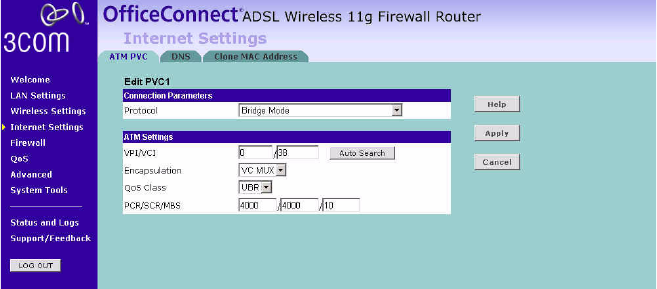
Bridge Mode
If the ISP limits some specific computers to access Internet, that means
only the traffic to/from these computers will be forwarded and the other
will be filtered. In this case, bridge modem is used to connect to the ISP.
The ISP will generally give one Internet account and limit only one
computer to access the Internet. Check with your ISP to determine if this
mode is used for your DSL connection. To configure the settings correctly,
you should obtain the information from your ISP.
Figure 47 Bridge Mode Screen
1Select Bridge Mode from the Protocol drop-down menu.
2Enter the VPI and VCI parameters in the VPI and VCI fields. You can click
Auto Search to automatically find out this information.
3Select the encapsulation type (LLC or VC MUX) in the Encapsulation Type
field. This information should be provided to you by your ISP.
60 CHAPTER 5: CONFIGURING THE ROUTER
4Select the type of Quality of Service that you want from the QoS Class
drop-down menu.
■CBR (constant bit rate): the CBR service class is intended for
real-time applications, for example, those requiring tightly
constrained delay and delay variation, such as voice and video
applications. The consistent availability of a fixed quantity of
bandwidth is considered appropriate for CBR service.
■VBR (variable bit rate): QoS class defined by the ATM Forum for
ATM networks. VBR is subdivided into a real time (RT) class and
non-real time (NRT) class. VBR (RT) is used for connections in which
there is a fixed timing relationship between samples. VBR (NRT) is
used for connections in which there is no fixed timing relationship
between samples, but that still need a guaranteed QoS. Compare
with ABR, CBR, and UBR.
■UBR (unspecified bit rate): the UBR service class is intended for
delay-tolerant or non-real-time applications, for example, those
which do not require tightly constrained delay and delay variation,
such as traditional computer communications applications. The
UBR service may be considered as "best effort service".
5Enter the PCR/SCR/MBS values.
6Click Apply.
Internet Settings 61
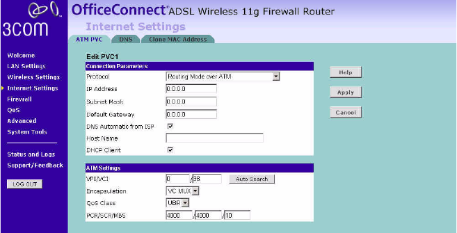
Routing Mode over ATM (RFC 1483 Routed Mode)
This mode is commonly used with either dynamic or static IP addressing.
In this mode the WAN ADSL port will be configured with an IP address
provided by the ISP. To configure the settings correctly, you should obtain
the information on this page from your ISP.
Figure 48 Routing Mode over ATM Screen
1Select Routing Mode over ATM from the Protocol drop-down menu.
2Enter the IP address, Subnet Mask and Default Gateway information
provided by your ISP into the IP address, Subnet Mask and Default
Gateway fields.
3Check the DNS Automatic from ISP checkbox, if your ISP automatically
configure DNS. However, if you need to configure DNS manually, enter
the IP address in the DNS Address field. (If your ISP uses a secondary DNS,
enter the IP address in the Secondary DNS Address field).
4Enter the host name in the Host Name filed.
5If your ISP uses DHCP to automatically assign IP addresses, check the
DHCP Client checkbox.
6Enter the VPI and VCI parameters provided to you by your ISP in the VPI
and VCI fields. You can click Auto Search to automatically find out this
information.
7Select the encapsulation type (LLC or VC MUX) in the Encapsulation field.
This information should be provided to you by your ISP.
62 CHAPTER 5: CONFIGURING THE ROUTER
8Select the type of Quality of Service that you want from the QoS Class
drop-down menu.
■CBR (constant bit rate): the CBR service class is intended for
real-time applications, for example, those requiring tightly
constrained delay and delay variation, such as voice and video
applications. The consistent availability of a fixed quantity of
bandwidth is considered appropriate for CBR service.
■VBR (variable bit rate): QoS class defined by the ATM Forum for
ATM networks. VBR is subdivided into a real time (RT) class and
non-real time (NRT) class. VBR (RT) is used for connections in which
there is a fixed timing relationship between samples. VBR (NRT) is
used for connections in which there is no fixed timing relationship
between samples, but that still need a guaranteed QoS. Compare
with ABR, CBR, and UBR.
■UBR (unspecified bit rate): the UBR service class is intended for
delay-tolerant or non-real-time applications, for example, those
which do not require tightly constrained delay and delay variation,
such as traditional computer communications applications. The
UBR service may be considered as "best effort service".
9Enter the PCR/SCR/MBS values.
10 Click Apply.
Internet Settings 63
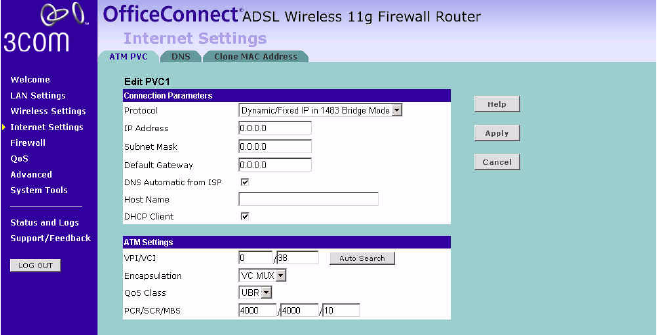
Dynamic/Fixed IP in 1483 Bridge Mode (For Multiple PCs)
Your ISP uses fixed/dynamic IP to provide the Internet connection. To
configure this function correctly, you should obtain the information on
this page from your ISP.
Figure 49 Dynamic/Fixed IP for Bridge Mode Screen
1Select Dynamic/Fixed IP for Bridge Mode from the Protocol drop-down
menu.
2Enter the IP address, Subnet Mask and Default Gateway information
provided by your ISP into the IP address, Subnet Mask and Default
Gateway fields.
3Check the DNS Automatic from ISP checkbox, if your ISP automatically
configure DNS. However, if you need to configure DNS manually, enter
the IP address in the DNS Address field. (If your ISP uses a secondary DNS,
enter the IP address in the Secondary DNS Address field).
4Enter the host name in the Host Name filed.
5If your ISP uses DHCP to automatically assign IP addresses, check the
DHCP Client checkbox.
6Enter the VPI and VCI parameters provided by your ISP in the VPI and VCI
fields. You can click Auto Search to automatically find out this
information.
7Select the encapsulation type (LLC or VC MUX) in the Encapsulation field.
This information will have been provided to you by your ISP.
64 CHAPTER 5: CONFIGURING THE ROUTER
8Select the type of Quality of Service that you want from the QoS Class
drop-down menu.
■CBR (constant bit rate): the CBR service class is intended for
real-time applications, for example, those requiring tightly
constrained delay and delay variation, such as voice and video
applications. The consistent availability of a fixed quantity of
bandwidth is considered appropriate for CBR service.
■VBR (variable bit rate): QoS class defined by the ATM Forum for
ATM networks. VBR is subdivided into a real time (RT) class and
non-real time (NRT) class. VBR (RT) is used for connections in which
there is a fixed timing relationship between samples. VBR (NRT) is
used for connections in which there is no fixed timing relationship
between samples, but that still need a guaranteed QoS. Compare
with ABR, CBR, and UBR.
■UBR (unspecified bit rate): the UBR service class is intended for
delay-tolerant or non-real-time applications, for example, those
which do not require tightly constrained delay and delay variation,
such as traditional computer communications applications. The
UBR service may be considered as "best effort service".
9Enter the PCR/SCR/MBS values.
10 Click Apply.
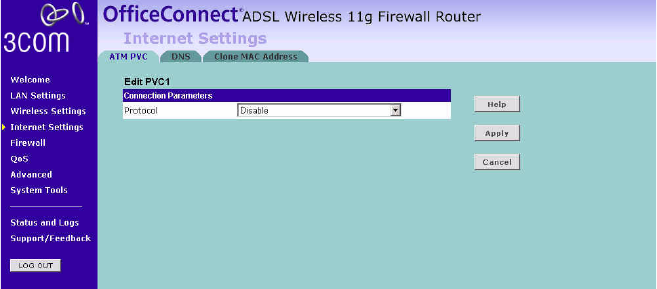
Disable
Selecting this option means that you do not want your Router to connect
to the Internet.
Figure 50 Disable Internet Connection Screen
Internet Settings 65
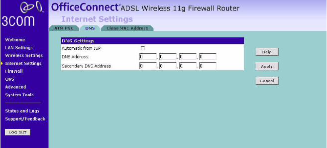
DNS Domain Name Service (or Server), an Internet service that translates
domain names into IP addresses. Because domain names are alphabetic,
they're easier to remember. The Internet however, is really based on IP
addresses. Every time you use a domain name, a DNS service must
translate the name into the corresponding IP address. For example, the
domain name www.example.com might translate to 198.105.232.4.
Check with your ISP for information on this page.
Figure 51 DNS Screen
If the DNS information is automatically provided by your ISP every time
you connect to it, check the Automatic from ISP checkbox.
If your ISP provided you with specific DNS addresses to use, enter them
into the appropriate fields on this screen and click Apply.
Many ISPs do not require you to enter this information into the Router. If
you are using a Static IP connection type, you may need to enter a
specific DNS address and secondary DNS address for your connection to
work properly. If your connection type is Dynamic, PPPoA or PPPoE, it is
likely that you do not have to enter a DNS address.
66 CHAPTER 5: CONFIGURING THE ROUTER
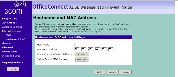
Hostname & Clone
MAC address
To configure the Hostname and Clone MAC Address information for your
Router, select Internet Settings, then go to the Clone MAC address tab.
The Hostname and MAC Address screen displays.
Figure 52 Hostname and MAC Address Screen
1Some ISPs require a host name. If your ISP has this requirement, enter the
host name in the Host Name field.
2Three different ways to configure the WAN MAC Address:
■If your ISP requires an assigned MAC address, enter the values in the
WAN MAC address field.
or
■If the computer you are now using is the one that was previously
connected directly to the cable modem, click Clone.
or
■To reset the MAC Address to the default, click Reset MAC.
3Click Apply to save the settings.
Firewall 67
Firewall From these pages, you can configure settings for the firewall.
Your Router is equipped with a firewall that will protect your network
from a wide array of common hacker attacks including Ping of Death
(PoD) and Denial of Service (DoS) attacks. You can turn the firewall
function off if needed. Turning off the firewall protection will not leave
your network completely vulnerable to hacker attacks, but 3Com
recommends that you leave the firewall enabled whenever possible.
SPI Stateful Packet Inspection (SPI) - The Intrusion Detection Feature of the
Router limits access for incoming traffic at the WAN port.
This feature is called a "stateful" packet inspection, because it examines
the contents of the packet to determine the state of the communications;
i.e., it ensures that the stated destination computer has previously
requested the current communication. This is a way of ensuring that all
communications are initiated by the recipient computer and are taking
place only with sources that are known and trusted from previous
interactions. In addition to being more rigorous in their inspection of
packets, stateful inspection firewalls also close off ports until connection
to the specific port is requested.
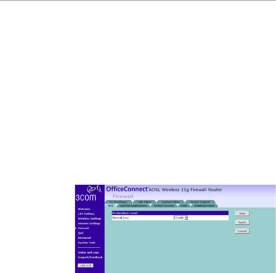
Figure 53 Firewall Screen
To enable the firewall function:
1Select the level of protection (High, Medium, or Low) that you desire from
the Firewall level drop-down menu.
2Click Apply.
68 CHAPTER 5: CONFIGURING THE ROUTER
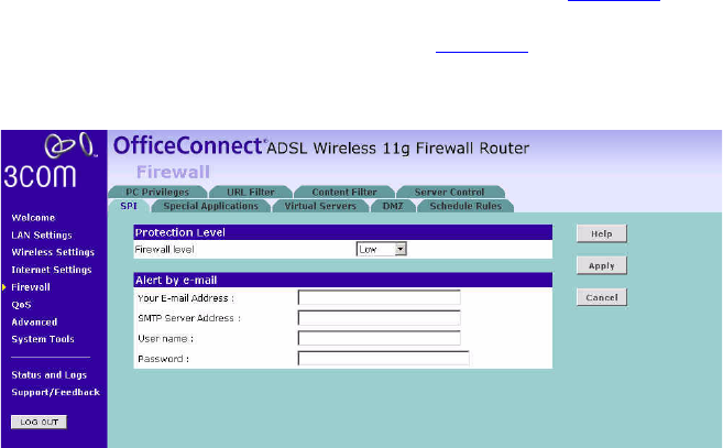
For low and medium levels of firewall protection, refer to Figure 54.
For high level of firewall protection, refer to Figure 55.
Figure 54 Low and Medium Level Firewall Protection Screen
When abnormal network activity occurs, an alerting email will be send
out to you, enter the following information to receive the email:
■Your E-mail Address
■SMTP Server Address
■User name
■Password
Firewall 69
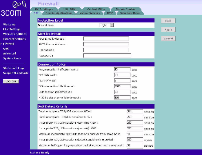
Figure 55 High Level Firewall Protection Screen
If you select high level of protection, you will need to configure additional
parameters for the firewall.
■Fragmentation half-open wait - Configures the number of seconds
that a packet state structure remains active. When the timeout value
expires, the router drops the un-assembled packet, freeing that
structure for use by another packet.
■TCP SYN wait - Defines how long the software will wait for a TCP
session to synchronize before dropping the session.
■TCP FIN wait - Specifies how long a TCP session will be maintained
after the firewall detects a FIN packet.
■TCP connection idle timeout - The length of time for which a TCP
session will be managed if there is no activity.
■UDP session idle timeout - The length of time for which a UDP session
will be managed if there is no activity.
■H.323 data channel idle timeout - The length of time for which an
H.323 session will be managed if there is no activity.
70 CHAPTER 5: CONFIGURING THE ROUTER
■Total incomplete TCP/UDP sessions HIGH - Defines the rate of new
unestablished sessions that will cause the software to start deleting
half-open sessions.
■Total incomplete TCP/UDP sessions LOW - Defines the rate of new
unestablished sessions that will cause the software to stop deleting
half-open sessions.
■Incomplete TCP/UDP sessions (per min) HIGH - Maximum number of
allowed incomplete TCP/UDP sessions per minute.
■Incomplete TCP/UDP sessions (per min) LOW - Minimum number of
allowed incomplete TCP/UDP sessions per minute.
■Maximum incomplete TCP/UDP sessions number from same host -
Maximum number of incomplete TCP/UDP sessions from the same
host.
■Incomplete TCP/UDP sessions detect sensitive time period - Length of
time before an incomplete TCP/UDP session is detected as incomplete.
■Maximum half-open fragmentation packet number from same host -
Maximum number of half-open fragmentation packets from the same
host.
■Half-open fragmentation detect sensitive time period - Length of time
before a half-open fragmentation session is detected as half-open.
■Flooding cracker block time - Length of time from detecting a flood
attack to blocking the attack.