Arcadyan Technology AR4505NW DIGITAL TRANSMISSION SYSTEM User Manual 3com
Arcadyan Technology Corporation DIGITAL TRANSMISSION SYSTEM 3com
Contents
- 1. USERS MANUAL 1 OF 4
- 2. USERS MANUAL 2 OF 4
- 3. USERS MANUAL 3 OF 4
- 4. USERS MANUAL 4 OF 4
USERS MANUAL 3 OF 4
Firewall 71
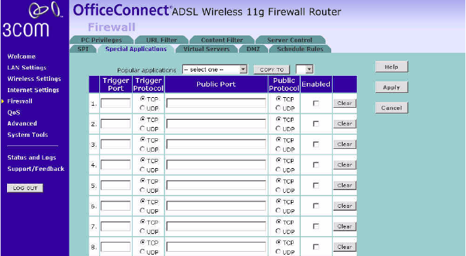
Special Applications Special Applications let you choose specific ports to be open for specific
applications to work properly with the Network Address Translation (NAT)
feature of the Router.
Figure 56 Special Applications Screen
A list of popular applications has been included to choose from. Select
your application from the Popular Applications drop-down menu. Then
select the row that you want to copy the settings to from the Copy To
drop-down menu, and click Copy To. The settings will be transferred to
the row that you specified. Click Apply to save the setting for that
application.
If your application is not listed, you will need to check with the
application vendor to determine which ports need to be configured. You
can manually enter the port information into the Router.
To manually enter the port information:
1Specify the trigger port (the one used by the application when it is
initialized) in the Trigger Port column, and specify whether the trigger is
TCP or UDP.
2Specify the Public Ports used by the application, that will need to be
opened up in the firewall for the application to work properly. Also
specify whether these ports are TCP or UDP.
3Check the Enabled checkbox, then click Apply.
72 CHAPTER 5: CONFIGURING THE ROUTER
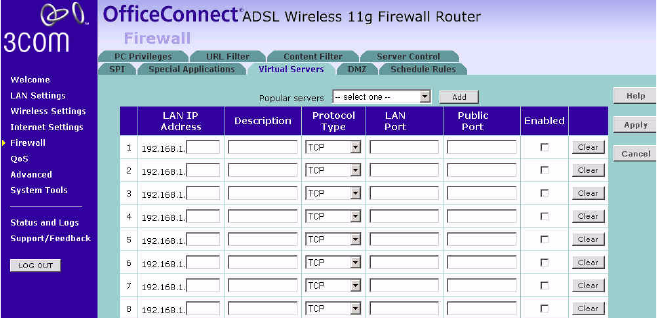
Virtual Servers The Virtual servers feature allows you to route external (Internet) calls for
services such as a web server (port 80), FTP server (Port 21), or other
applications through your Router to your internal network. Since your
internal computers are protected by a firewall, machines from the
Internet cannot get to them because they cannot be 'seen'.
If you need to configure the Virtual Server function for a specific
application, you will need to contact the application vendor to find out
which port settings you need.
The maximum number of virtual servers that can be configured is 20.
Figure 57 Virtual Servers Screen
A list of popular servers has been included to choose from. Select the
server from the Popular servers drop-down menu. Then click Add, your
selection will be added to the table.
If the server that you want to use is not listed in the drop-down menu,
you can manually add the virtual server to the table.
To manually configure your virtual servers:
1Enter the IP address, and the description in the spaces provided for the
internal machine.
2Select the protocol type (TCP, UDP, or both TCP and UDP) from the
drop-down menu.
3Specify the public port that will be seen by clients on the Internet, and the
LAN port which the traffic will be routed to.
Firewall 73
4You can enable or disable each Virtual Server entry by checking or
unchecking the appropriate Enabled checkbox.
5Click Apply to save the changes for each Virtual Server entry.
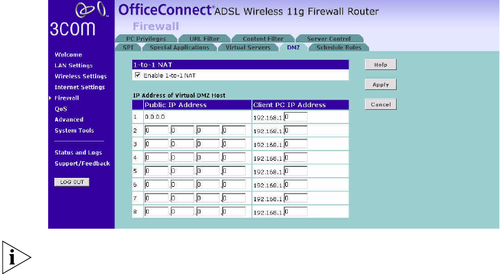
DMZ If you have a client PC that cannot run an Internet application properly
from behind the firewall, you can open the client up to unrestricted
two-way Internet access. This may be necessary if the NAT feature is
causing problems with an application such as a game or video
conferencing application.
Figure 58 DMZ Screen
Use this feature on a temporary basis. The computer in the DMZ is not
protected from hacker attacks.
To put a computer in the DMZ:
1Check the Enable 1-to-1 NAT checkbox.
2Enter the last digits of the LAN IP address in the Client PC IP Address field.
Enter the IP address (if known) that will be accessing the DMZ PC into the
Public IP Address field, so that only the computer on the Internet at this
address can access the DMZ PC without firewall protection. If the IP
address is not known, or if more than one PC on the Internet will need to
access the DMZ PC, then set the Public IP Address to 0.0.0.0.
3Click Apply.
74 CHAPTER 5: CONFIGURING THE ROUTER
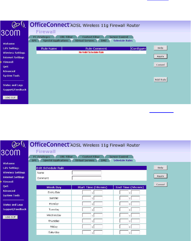
Schedule Rule The Router can be configured to restrict access to the Internet, email or
other network services at specific days and times. Define the time in this
page, and define the rules in the PC Privileges page (see page 75).
Figure 59 Schedule Rule Screen
1Click Add Rule to add a schedule rule (a screen similar to Figure 60 will
appear).
Figure 60 Add Schedule Rule Screen
2Enter a name and comment for the schedule rule in the Name and
Comment fields.
3Specify the schedule rules for the required days and times - note that all
times should be in 24 hour format.
4Click Apply.
Firewall 75
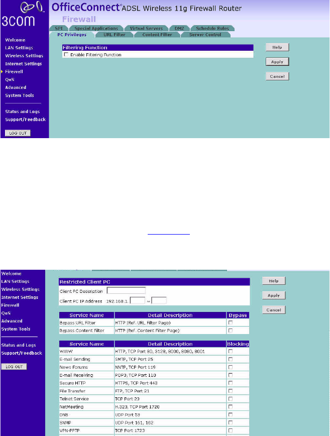
PC Privileges The Router can be configured to restrict access to the Internet, email or
other network services at specific days and times. Restriction can be set
for a single computer, a range of computers, or multiple computers.
You can define the traffic type permitted or not-permitted to the Internet.
Figure 61 PC Privileges Screen
To edit or delete specific existing filtering rules, click on Edit or Delete for
the appropriate filtering rule.
To configure a new filtering rule:
1Check the Enable Filtering Function checkbox.
2Click Add PC (a screen similar to Figure 62 will appear).
Figure 62 PC Privileges Add PC Screen

76 CHAPTER 5: CONFIGURING THE ROUTER
3Enter a description in the Client PC Description field, and the IP address or
IP address range into the Client PC IP Address fields.
4To bypass the URL Filter and Content Filter, check the corresponding
Bypass checkbox.
5Select the services to be blocked. A list of popular services is given on this
screen, to block a particular service, check the appropriate Blocking
checkbox.
If the service to be restricted is not listed here, you can enter a custom
range of ports at the bottom of the page, under User Defined Blocked
Ports.
6If you want the restriction to apply only at certain times, select the
schedule rule to apply from the Schedule Rule drop-down menu.
Note that schedule rules are defined on the Schedule Rules screen
(see page 74).
7Click Apply to add the settings.
Firewall 77
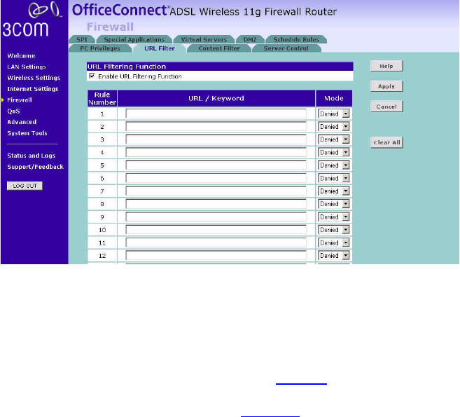
URL Filter To configure the URL filter feature, use the table on the URL Filter screen
to specify the Web sites (www.somesite.com) and/or keywords you want
to filter on your network.
For example, entering a keyword of xxx would block access to any URL
that contains the string xxx.
Figure 63 URL Filter Screen
1Check the Enable URL Filtering Function checkbox.
2Enter the URL address or keywords in the URL/Keyword field.
3Select Denied or Allowed from the Mode drop-down menu.
To complete this configuration, you will need to create or modify the
filtering rule in the PC Privileges screen (see page 75).
From the PC Privileges Add PC screen (Figure 62), if you check the two
options: Bypass URL Filter, and Bypass Content Filter, then the Web sites
and keywords defined in this page will not be filtered out.
78 CHAPTER 5: CONFIGURING THE ROUTER
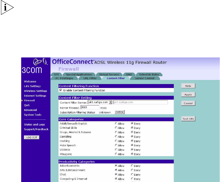
Content Filter
You can use the list on the Content Filter page to specify the type of
content that you want to filter out.
The Router comes with a 14-day free trial of the 3Com Content Filter
Service (3CSBCFS). To activate the 14-day free trial of the service, you
must first register your Router at www.3com.com. To continue using the
service after the trial period, you must purchase the 12-month
subscription license.
Figure 64 Content Filter Screen
To configure the Content Filter feature:
1Check the Enable Content Filtering Function checkbox.
2Select the server that you want to use from the Content Filter Server
drop-down menu. If the server you want to use is not listed, enter the
server address manually.
3Define the time in the Server Timeout field (the default value is 3000ms).
If the Content Filter Server does not respond within this time period, the
Router will use the default content filter rule. The default rule is either
Allow or Deny None of the above (Uncategorized URL). You can configure
this rule at the bottom of the Content Filter page.
Firewall 79
4If you are not sure about your subscription status, click CHECK in
Subscription Filtering Status to find out if you have a current, valid
subscription.
5Subjects are listed under Core Categories and Productivity Categories.
You can define what content should be viewed/blocked using the
Allow/Deny option. The Deny option is used to filter out the content that
contains the specific subject matter. Content with a specific subject
matter will not be filtered out if the Allow option is checked.
6Click Apply for the changes to take effect.
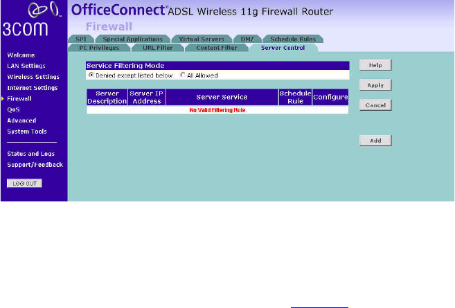
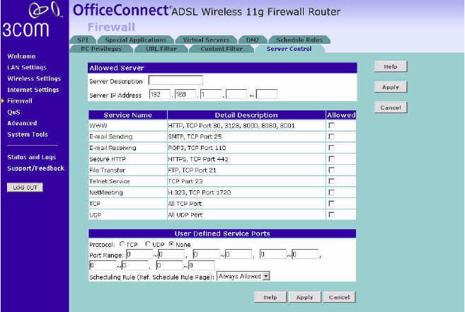
Server Control The Router can be configured to restrict access to the Internet, email or
other network services at specific days and times. Restriction can be set
for the servers.
You can define the traffic type permitted or not-permitted to the Internet.
Figure 65 Server Control Screen
In the Service Filtering Mode, select one option:
■Denied except listed below.
■All Allowed.
Click Add to add a new entry to the table (see Figure 66).
80 CHAPTER 5: CONFIGURING THE ROUTER
Figure 66 Server Control Add Server Screen
1Enter a description in the Server Description field, and the IP address or IP
address range into the Server IP Address fields.
2Select the services that will be allowed. A list of popular services is given
on this screen, to unblock a particular service, check the appropriate
Allowed checkbox.
If the service to be allowed is not listed here, you can enter a custom
range of ports at the bottom of the page, under User Defined Service
Ports.
3Select the time that the rule will be enforced from the Scheduling Rule
drop-down menu.
4Click Apply to save the settings.
Quality of Service 81
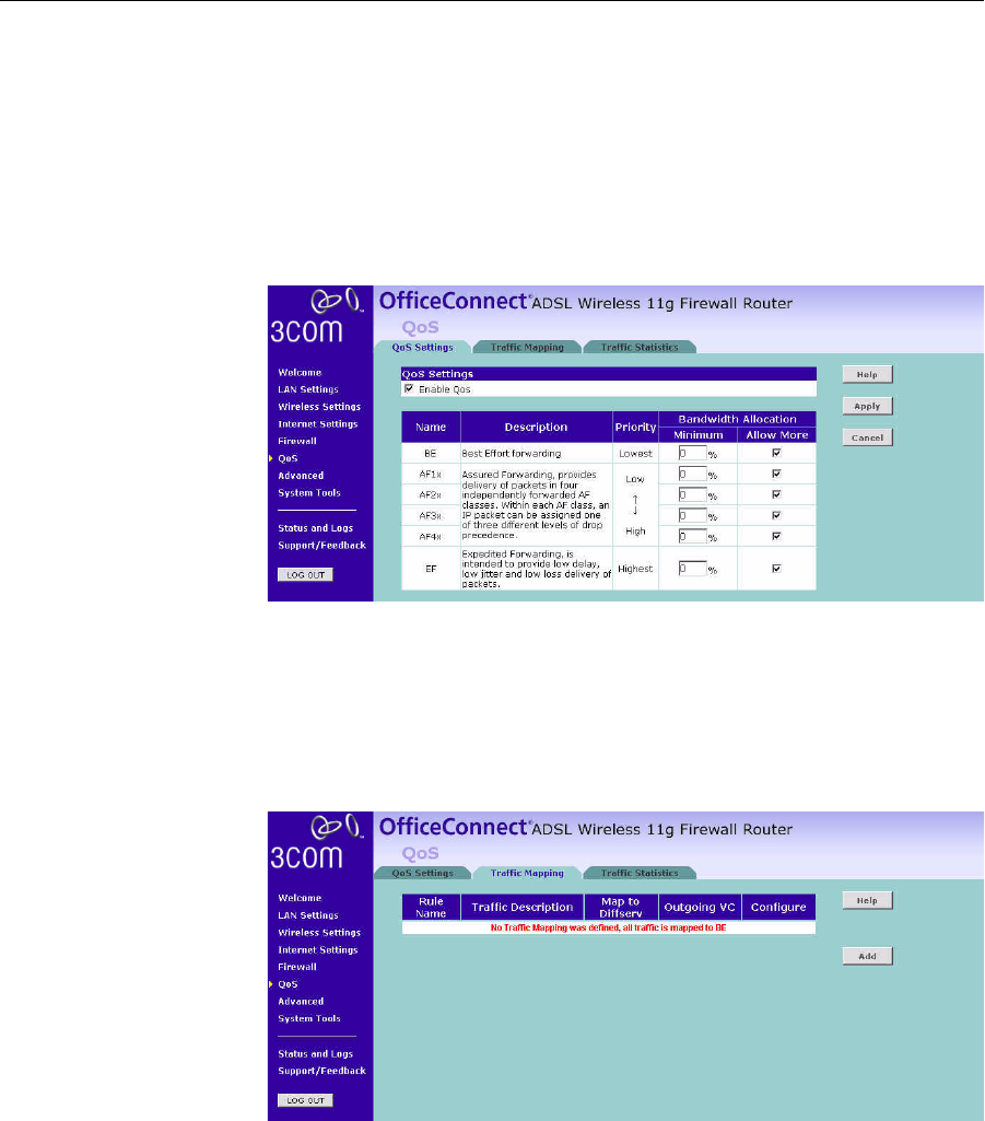
Quality of Service The QoS (Quality of Service) function allows you to differentiate your
network traffic and provide it with high-priority forwarding service.
QoS Settings The bandwidth gap between LAN and WAN may significantly degrade
performance of critical network applications, such as VoIP, gaming, and
VPN. This QoS function allows you to classify traffic of applications and
provides them with differentiated services (Diffserv).
Figure 67 QoS Settings Screen
Define the minimum percentage of bandwidth for each type of traffic.
Traffic Mapping You can define up to 16 rules to classify traffic into Diffserv forwarding
groups and outgoing VCs in this page.
Figure 68 Traffic Mapping screen
82 CHAPTER 5: CONFIGURING THE ROUTER
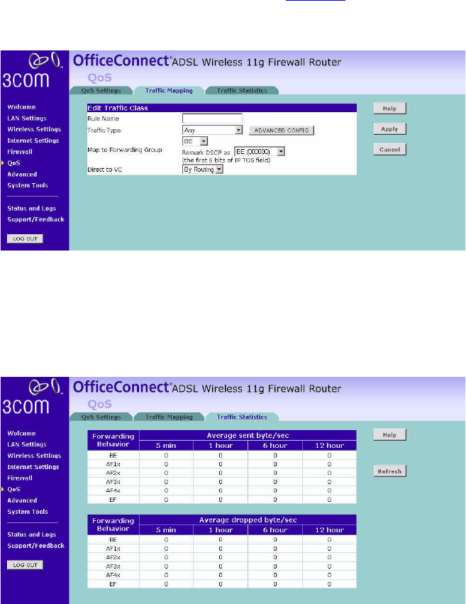
Click Add to add a new traffic class rule (see Figure 69).
Figure 69 Add New Traffic Class Rule Screen
Traffic Statistics This page shows the WAN outbound traffic statistics of all the Diffserv
forwarding groups in the last 12 hours. This page automatically updates
every 5 minutes.
Figure 70 Traffic Statistics Screen
Advanced 83
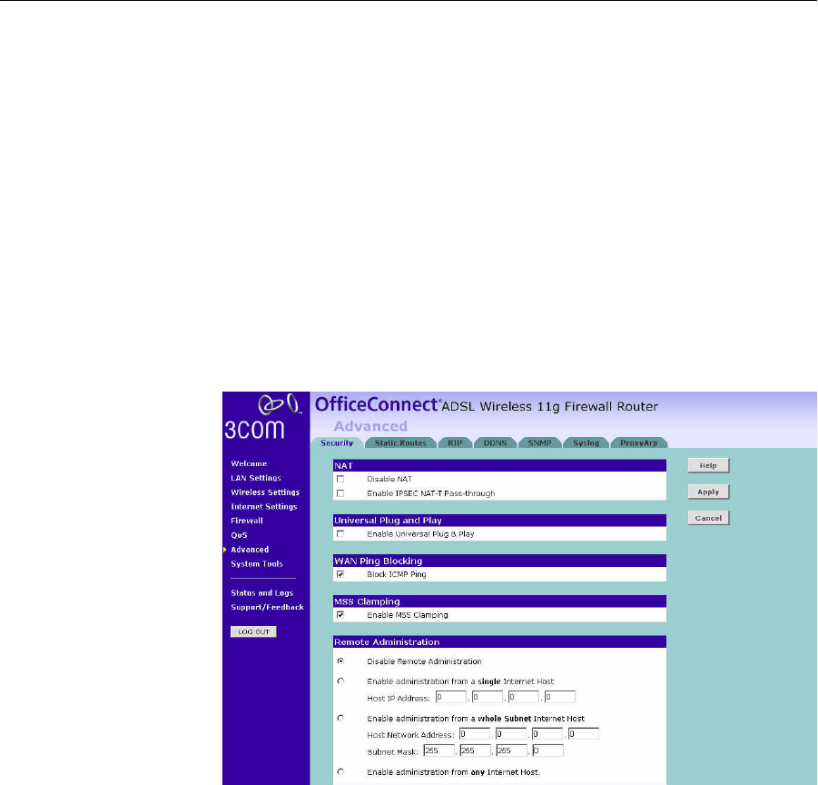
Advanced From the Advanced screen, you can configure:
■Security
■Static Routes
■RIP
■DDNS
■SNMP
■Syslog
■Proxy Arp
Security Using this advanced security settings page to set the detail settings for
the Router.
Figure 71 Security Screen
■NAT — Before you enable NAT (Network Address Translation), make
sure you have changed the administrator password. NAT is the
method by which the router shares the single IP address assigned by
your ISP with the computers on your network.
This function should only be disabled by advanced users, and if your
ISP assigns you multiple IP addresses or you need NAT disabled for an
advanced system configuration. If you have a single IP address and
84 CHAPTER 5: CONFIGURING THE ROUTER
you turn NAT off, the computers on your network will not be able to
access the Internet. Other problems may also occur.
■IPSEC NAT-T Pass-through — NAT-T (NAT Traversal) is an Internet
Draft proposed to IETF in order to help the problems associated
with passing IPsec traffic through NAT Routers. For NAT-T to work,
both ends of the connection need to support this function. Ensure
that you select NAT-T only if it is needed as it will reduce LAN-WAN
throughput. This Router supports NAT-T draft 2 implementation.
■Universal Plug and Play — This is a technology that offers seamless
operation of voice messaging, video messaging, games, and other
applications that are Universal Plug and Play compliant. Some
applications require the Router's firewall to be configured in a specific
way to operate properly. This usually requires opening TCP and UDP
ports and in some instances setting trigger ports. An application that
is Universal Plug and Play compliant has the ability to communicate
with the Router, basically "telling" the Router which way it needs the
firewall configured. The Router ships with the Universal Plug and Play
feature disabled. If you are using any applications that are Universal
Plug and Play compliant, and want to take advantage of the Universal
Plug and Play features, you can enable this feature. Simply check the
Enable Universal Plug and Play checkbox. Click Apply to save the
change.
■WAN Ping Blocking — Computer hackers use what is known as
"Pinging" to find potential victims on the Internet. By pinging a
specific IP address and receiving a response from the IP address, a
hacker can determine that something of interest might be there.
The Router can be set up so it will not respond to an ICMP Ping from
the outside. This heightens the level of security of your Router.
To turn off the ping response, check Block ICMP Ping and click Apply;
the router will not respond to an ICMP ping from the Internet.
■MSS Clamping — You might not be able to browse some Web sites or
to send email messages that contain attachments from an Internet
Connection Sharing client computer if your outbound connection is
through a Windows XP-based Internet Connection Sharing host
computer that uses Point-to-Point Protocol over Ethernet (PPPoE).
This issue may occur if the Windows XP-based Internet Connection
Sharing host computer uses a smaller Maximum Transmission Unit
(MTU) size on the WAN interface (the PPPoE connection to the
Internet) than it uses on the private interface (the Ethernet connection
to the Internet Connection Sharing client). If a packet is larger than
the MTU size on the WAN interface, the client sends an Internet

Advanced 85
Control Message Protocol (ICMP) error to the external server to
request that the server negotiate the TCP Maximum Segment Size
(MSS). However, this message may be blocked by some firewalls.
When this occurs, the packet is dropped. To allow the message to go
through the firewall, enable MSS Clamping. MSS clamping will make
Internet Connection Sharing to set the MSS value low enough to
match the external interface.
■Remote Administration — This feature allows you to make changes to
your Router’s settings from anywhere on the Internet. Four options are
available:
■If you do not want to use this feature, select Disable Remote
Administration.
■Select Enable administration from a single Internet Host, and enter
the IP address, to allow only one computer to use the remote
administration. This is more secure, as only the specified IP address
will be able to manage the Router.
■Select Enable administration from a whole Subnet Internet Host,
and enter the IP address and subnet mask, to allow PCs from that
specific subnet group to use the remote administration.
■Select Enable administration from any Internet Host, this allows
any computer to access the router remotely.
Before you enable this function, ensure that you have set the
Administration Password.
86 CHAPTER 5: CONFIGURING THE ROUTER
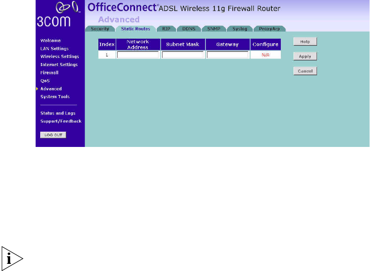
Static Routes You can configure static routes in this page.
To add a static route entry to the table, click Add.
To change an existing entry, click Edit. To delete an entry, click Delete.
Figure 72 Static Routes Screen
This screen shows a list of current static route entries. For each entry, the
following information is displayed:
■Index — the index of the entry.
■Network Address — the network address of the route.
■Subnet Mask — the subnet mask of the route.
A network address of 0.0.0.0 and a subnet mask of 0.0.0.0 indicates the
default route.
■Gateway — the router used to route data to the network specified by
the network address.
After you have finished making changes to the table, click Apply.
Advanced 87
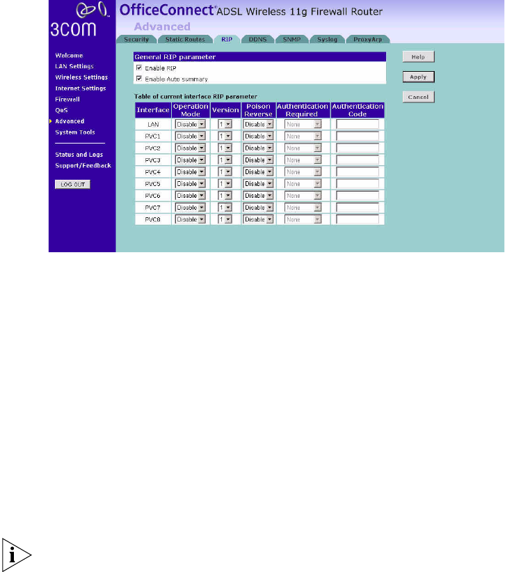
RIP RIP (Routing Information Protocol) - RIP allows the network administrator
to set up routing information on one RIP-enabled device and send that
information to all RIP-enabled devices on the network.
Figure 73 RIP Parameter Screen
You can set up RIP independently on both LAN and WAN interfaces.
1Check the Enable RIP checkbox.
2Check the Enable Auto summary checkbox. Auto summarization sends
simplified routing data to other RIP-enabled devices rather than full
routing data.
3Select the Operation Mode:
■Disabled — RIP is not enabled for the WAN or LAN interface.
■Enabled — RIP is enabled for the WAN or LAN interface. The router
will transmit RIP update information to other RIP-enabled devices.
■Silent — RIP is enabled, however the router only receives RIP update
messages, it will not transmit any messages itself.
4In the Version field, select 1 or 2.
3Com recommends that you only use RIPv1 if there is an existing
RIP-enabled device on your network that does not support RIPv2. In all
other cases, you should use RIPv2.
88 CHAPTER 5: CONFIGURING THE ROUTER
5Use the Poison Reverse drop-down menu to enable or disable Poison
Reverse on the router. Enabling Poison Reverse on your Router allows it to
indicate to other RIP-enabled devices that they have both routes that
point to each other, preventing data loops.
6Use the Authentication Required field to choose the mode of
authentication:
■None — Switches off authentication on the specified interface.
■Password — An unencrypted text password that needs to be set on all
RIP-enabled devices connected to this router. RIP information is not
shared between devices whose passwords do not match.
7In the Authentication Code field, enter the password that is required if
the Password option has been selected.
8Click Apply.
DDNS The Router provides a list of dynamic DNS providers for you to choose
from. Dynamic Domain Name Server (DDNS) enables you to map a static
domain name to a dynamic IP address.
The Router supports five DDNS providers:
■DynDNS.org
■TZO.com
■Dt DNS.com
■No-IP.com
■Zoneedit.com