Arcadyan Technology AR4505NW DIGITAL TRANSMISSION SYSTEM User Manual 3com
Arcadyan Technology Corporation DIGITAL TRANSMISSION SYSTEM 3com
Contents
- 1. USERS MANUAL 1 OF 4
- 2. USERS MANUAL 2 OF 4
- 3. USERS MANUAL 3 OF 4
- 4. USERS MANUAL 4 OF 4
USERS MANUAL 1 OF 4

http://www.3com.com/
Part No. DUA100A-72AAA02
Published February 2006
OfficeConnect®
User Guide
Model
OfficeConnect ADSL Wireless 54Mbps 11g Firewall Router
WL-552
3Com Corporation
350 Campus Drive,
Marlborough, MA
USA 01752-3064
Copyright © 2004, 2005, 2006, 3Com Corporation. All rights reserved. No part of this documentation may be
reproduced in any form or by any means or used to make any derivative work (such as translation,
transformation, or adaptation) without written permission from 3Com Corporation.
3Com Corporation reserves the right to revise this documentation and to make changes in content from time
to time without obligation on the part of 3Com Corporation to provide notification of such revision or change.
3Com Corporation provides this documentation without warranty, term, or condition of any kind, either
implied or expressed, including, but not limited to, the implied warranties, terms or conditions of
merchantability, satisfactory quality, and fitness for a particular purpose. 3Com may make improvements or
changes in the product(s) and/or the program(s) described in this documentation at any time.
If there is any software on removable media described in this documentation, it is furnished under a license
agreement included with the product as a separate document, in the hard copy documentation, or on the
removable media in a directory file named LICENSE.TXT or !LICENSE.TXT. If you are unable to locate a copy,
please contact 3Com and a copy will be provided to you.
UNITED STATES GOVERNMENT LEGEND
If you are a United States government agency, then this documentation and the software described herein are
provided to you subject to the following:
All technical data and computer software are commercial in nature and developed solely at private expense.
Software is delivered as “Commercial Computer Software” as defined in DFARS 252.227-7014 (June 1995) or
as a “commercial item” as defined in FAR 2.101(a) and as such is provided with only such rights as are
provided in 3Com’s standard commercial license for the Software. Technical data is provided with limited rights
only as provided in DFAR 252.227-7015 (Nov 1995) or FAR 52.227-14 (June 1987), whichever is applicable.
You agree not to remove or deface any portion of any legend provided on any licensed program or
documentation contained in, or delivered to you in conjunction with, this User Guide.
Unless otherwise indicated, 3Com registered trademarks are registered in the United States and may or may not
be registered in other countries.
3Com, and the 3Com logo are registered trademarks of 3Com Corporation.
Intel and Pentium are registered trademarks of Intel Corporation. Microsoft, MS-DOS, Windows, and Windows
NT are registered trademarks of Microsoft Corporation. Novell and NetWare are registered trademarks of
Novell, Inc. UNIX is a registered trademark in the United States and other countries, licensed exclusively
through X/Open Company, Ltd.
Netscape Navigator is a registered trademark of Netscape Communications.
JavaScript is a trademark of Sun Microsystems
Wi-Fi and the Wi-Fi logo are registered trademarks of the WI-Fi Alliance.
IEEE and 802 are trademarks of the Institute of Electrical and Electronics Engineers, Inc.
All other company and product names may be trademarks of the respective companies with which they are
associated.
ENVIRONMENTAL STATEMENT
It is the policy of 3Com Corporation to be environmentally-friendly in all operations. To uphold our policy, we
are committed to:
Establishing environmental performance standards that comply with national legislation and regulations.
Conserving energy, materials and natural resources in all operations.
Reducing the waste generated by all operations. Ensuring that all waste conforms to recognized environmental
standards. Maximizing the recyclable and reusable content of all products.
Ensuring that all products can be recycled, reused and disposed of safely.
Ensuring that all products are labelled according to recognized environmental standards.
Improving our environmental record on a continual basis.
End of Life Statement
3Com processes allow for the recovery, reclamation and safe disposal of all end-of-life electronic components.
Regulated Materials Statement
3Com products do not contain any hazardous or ozone-depleting material.
Environmental Statement about the Documentation
The documentation for this product is printed on paper that comes from sustainable, managed forests; it is
fully biodegradable and recyclable, and is completely chlorine-free. The varnish is environmentally-friendly, and
the inks are vegetable-based with a low heavy-metal content.

CONTENTS
ABOUT THIS GUIDE
Naming Convention 7
Conventions 8
Feedback About This User Guide 8
Related Documentation 9
INTRODUCING THE ROUTER
OfficeConnect ADSL Wireless 11g Firewall Router 11
Router Advantages 13
Package Contents 13
Minimum System and Component Requirements 14
Physical Features 14
INSTALLING THE ROUTER
Introduction 17
Safety Information 17
Positioning the Router 17
Using the Rubber Feet 18
Powering Up the Router 18
Connecting the Router 18
SETTING UP YOUR COMPUTERS
Obtaining an IP Address Automatically 23
Windows 2000 23
Windows XP 25
Windows 98/ME 25
Macintosh 25
Disabling PPPoE and PPTP Client Software 26
Disabling Web Proxy 26

RUNNING THE SETUP WIZARD
Accessing the Setup Wizard 27
Setup Wizard - Change Password 30
Setup Wizard - Time and Time Zone 30
Setup Wizard - Connection Type 31
Setup Wizard - LAN Settings 36
Setup Wizard - Wireless Settings 37
Setup Wizard - Configuration Summary 38
CONFIGURING THE ROUTER
Navigating Through the Router Configuration Pages 39
Main Menu 39
Welcome Screen 39
Status 39
LAN Settings 40
LAN Settings 40
DHCP Clients List 41
Wireless Settings 43
Configuration 44
Encryption 45
Connection Control 50
Client List 51
WDS Settings 51
Advance 52
Profile 53
Internet Settings 54
ATM PVC 54
DNS 65
Hostname & Clone MAC address 66
Firewall 67
SPI 67
Special Applications 71
Virtual Servers 72
DMZ 73
Schedule Rule 74
PC Privileges 75

URL Filter 77
Server Control 79
Quality of Service 81
QoS Settings 81
Traffic Mapping 81
Traffic Statistics 82
Advanced 83
Security 83
Static Routes 86
RIP 87
DDNS 88
SNMP 90
Syslog 91
Proxy ARP 92
System Tools 93
Restart Router 93
Configuration 93
Upgrade 94
Time Zone 95
Ping 96
Traceroute 97
DNS Lookup 98
Status and Logs 99
Status 99
ADSL Status 99
ATM PVC Status 100
Routing Table 100
Logs 101
Support/Feedback 102
Support 102
Feedback 102
TROUBLESHOOTING
Basic Connection Checks 103
Browsing to the Router Configuration Screens 103
Connecting to the Internet 104
Forgotten Password and Reset to Factory Defaults 104

Wireless Networking 105
Recovering from Corrupted Software 107
Frequently Asked Questions 108
IP ADDRESSING
The Internet Protocol Suite 109
Managing the Router over the Network 109
IP Addresses and Subnet Masks 109
How does a Device Obtain an IP Address and Subnet Mask? 111
DHCP Addressing 111
Static Addressing 111
Auto-IP Addressing 111
TECHNICAL SPECIFICATIONS
OfficeConnect ADSL Wireless 11g Firewall Router 113
Standards 115
SAFETY INFORMATION
END USER SOFTWARE LICENSE AGREEMENT
OBTAINING SUPPORT FOR YOUR PRODUCT
Register Your Product 123
Purchase Value-Added Services 123
Troubleshoot Online 124
Access Software Downloads 124
Telephone Technical Support and Repair 124
Contact Us 125

GLOSSARY
REGULATORY NOTICES
INDEX

ABOUT THIS GUIDE
This guide describes how to install and configure the OfficeConnect ADSL
Wireless 11g Firewall Router (3CRWD100x-72).
This guide is intended for use by those responsible for installing and
setting up network equipment; consequently, it assumes a basic working
knowledge of LANs (Local Area Networks) and Internet Routers.
If a release note is shipped with the ADSL 11g Wireless Router and
contains information that differs from the information in this guide,
follow the information in the release note.
Most user guides and release notes are available in Adobe Acrobat
Reader Portable Document Format (PDF) on the 3Com World Wide Web
site:
http://www.3com.com
Naming Convention Throughout this guide, the OfficeConnect ADSL Wireless 11g Firewall
Router is referred to as the “Router”.
Category 3 and Category 5 Twisted Pair Cables are referred to as Twisted
Pair Cables throughout this guide.
8ABOUT THIS GUIDE
Conventions Table 1 and Table 2 list conventions that are used throughout this guide.
Feedback About
This User Guide
Your suggestions are very important to us. They will help make our
documentation more useful to you. Please e-mail comments about this
document to 3Com at:
pddtechpubs_comments@3com.com
Please include the following information when commenting:
■Document title
■Document part number (on the title page)
■Page number (if appropriate)
Tab le 1 Notice Icons
Icon Notice Type Description
Information note Information that describes important features or
instructions.
Caution Information that alerts you to potential loss of data or
potential damage to an application, system, or device.
Warning Information that alerts you to potential personal
injury.
Tab le 2 Text Conventions
Convention Description
The words “enter”
and “type” When you see the word “enter” in this guide, you must type
something, and then press Return or Enter. Do not press
Return or Enter when an instruction simply says “type.”
Keyboard key names If you must press two or more keys simultaneously, the key
names are linked with a plus sign (+). Example:
Press Ctrl+Alt+Del
Words in italics Italics are used to:
■Emphasize a point.
■Denote a new term at the place where it is defined in the
text.
■Identify menu names, menu commands, and software
button names. Examples:
From the Help menu, select Contents.
Click OK.

Related Documentation 9
Example:
■OfficeConnect ADSL Wireless 11g Firewall Router User Guide
■Part Number DUA100A-72AAA01
■Page 24
Do not use this e-mail address for technical support questions. For
information about contacting Technical Support, please refer to
Appendix C.
Related
Documentation
In addition to this guide, each Router document set includes one
Installation Guide. This guide contains the instructions you need to install
and configure your Router.
10 ABOUT THIS GUIDE

1INTRODUCING THE ROUTER
Welcome to the world of networking with 3Com®. In the modern
business environment, communication and sharing information is crucial.
Computer networks have proved to be one of the fastest modes of
communication but, until recently, only large businesses could afford the
networking advantage.
OfficeConnect ADSL
Wireless 11g
Firewall Router
The OfficeConnect ADSL Wireless 11g Firewall Router is designed to
provide a cost-effective means of sharing a single broadband Internet
connection amongst several wired and wireless computers. The Router
also provides protection in the form of an electronic “firewall” preventing
anyone outside of your network from seeing your files or damaging your
computers. The Router can also prevent your users from accessing Web
sites which you find unsuitable.
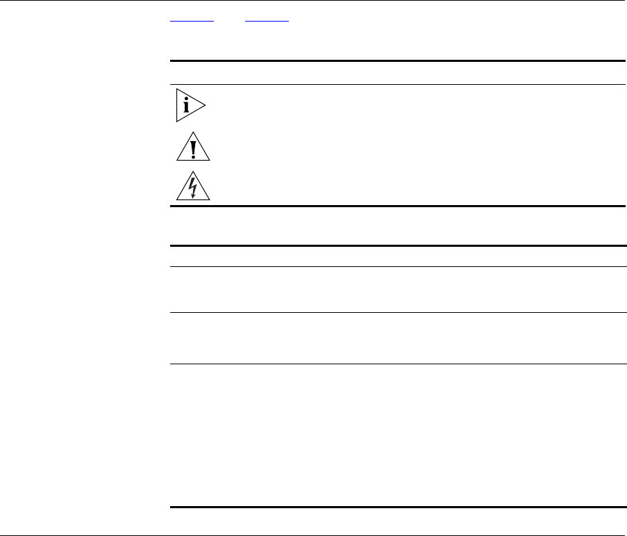
Figure 1 shows an example network without a Router. In this network,
only one computer is connected to the Internet. This computer must
always be powered on for the other computers on the network to access
the Internet.
12 CHAPTER 1: INTRODUCING THE ROUTER
Figure 1 Example Network Without a Router
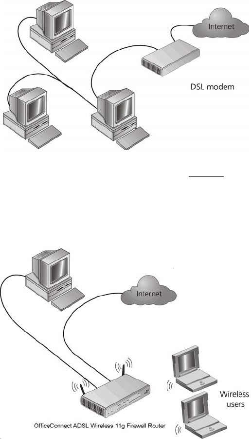
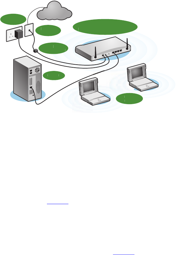
When you use the Router in your network (Figure 2), it becomes your
connection to the Internet. Connections can be made directly to the
Router, or to an OfficeConnect Switch or Hub, expanding the number of
computers you can have in your network.
Figure 2 Example Network Using a Firewall Router

Router Advantages 13
Router Advantages The advantages of the Router include:
■Shared Internet connection for both wired and wireless computers
■High speed 802.11g wireless networking
■No need for a dedicated, “always on” computer serving as your
Internet connection
■Cross-platform operation for compatibility with Windows, Unix and
Macintosh computers
■Easy-to-use, Web-based setup and configuration
■Provides centralization of all network address settings (DHCP)
■Acts as a Virtual server to enable remote access to Web, FTP, and other
services on your network
■Security — Firewall protection against Internet hacker attacks and
encryption to protect wireless network traffic
Package Contents The Router kit includes the following items:
■One OfficeConnect ADSL Wireless 11g Firewall Router
■One power adapter for use with the Router
■Four rubber feet
■One Telephone Cable
■One CD-ROM containing this User Guide
■Installation Guide
■One Support and Safety Information Sheet
■One Warranty Flyer
If any of these items are missing or damaged, please contact your retailer.
14 CHAPTER 1: INTRODUCING THE ROUTER
Minimum System
and Component
Requirements
Your Router requires that the computer(s) and components in your
network be configured with at least the following:
■A computer with an operating system that supports TCP/IP
networking protocols (for example Windows 98/NT/Me/2000/XP, Unix,
Mac OS 8.5 or higher).
■An Ethernet 10 Mbps or 10/100 Mbps NIC for each computer to be
connected to the four-port switch on your Router.
■An 802.11b or 802.11g wireless NIC.
■An active ADSL subscription and connection.
■A Web browser that supports JavaScript, such as Netscape 4.7 or
higher, Internet Explorer 5.0 or higher, or Mozilla 1.2.1 or higher.
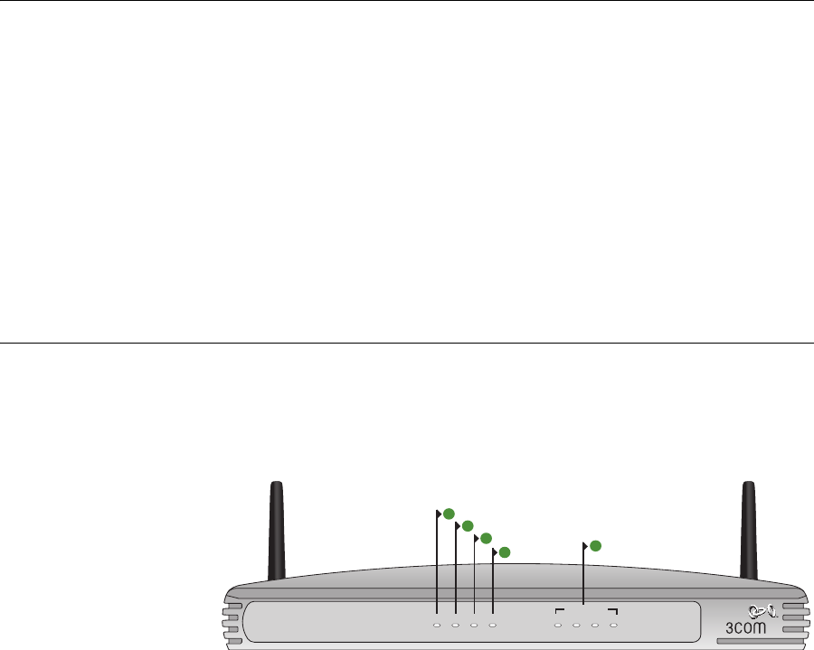
Physical Features The front panel of the Router contains a series of indicator lights (LEDs)
that help describe the state of various networking and connection
operations.
Figure 3 Router - Front Panel
1Power LED
Green
Indicates that the Router is powered on.
2SYNC LED
Green
If the LED is on it indicates that DSL connection is present. This LED
flashes during configuration at power up.
OfficeConnect ADSL Wireless 11g Firewall Router
3CRWDR100A-72
LAN Status
Power SYNC Online WLAN 1 2 3 4
Green = 100M, Yellow = 10M, Flash = Activity
1
5
2
4
3
Physical Features 15
3Online LED
Green
If this LED is on, your username/password has been authenticated
successfully with your ISP.
4 Wireless LAN (WLAN) Status LED
Green
If the LED is on it indicates that wireless networking is enabled. If the LED
is flashing, the link is OK and data is being transmitted or received. If the
LED is off, the Wireless LAN has been disabled in the Router, or there is a
problem. Refer to Chapter 6 “Troubleshooting”.
5 LAN Status LEDs
Green
If the LED is on, the link between the port and the next piece of network
equipment is OK. If the LED is flashing, the link is OK and data is being
transmitted or received. If the LED is off, nothing is connected, or the
connected device is switched off, or there is a problem with the
connection (refer to Chapter 6 “Troubleshooting”). The port will
automatically adjust to the correct speed and duplex.
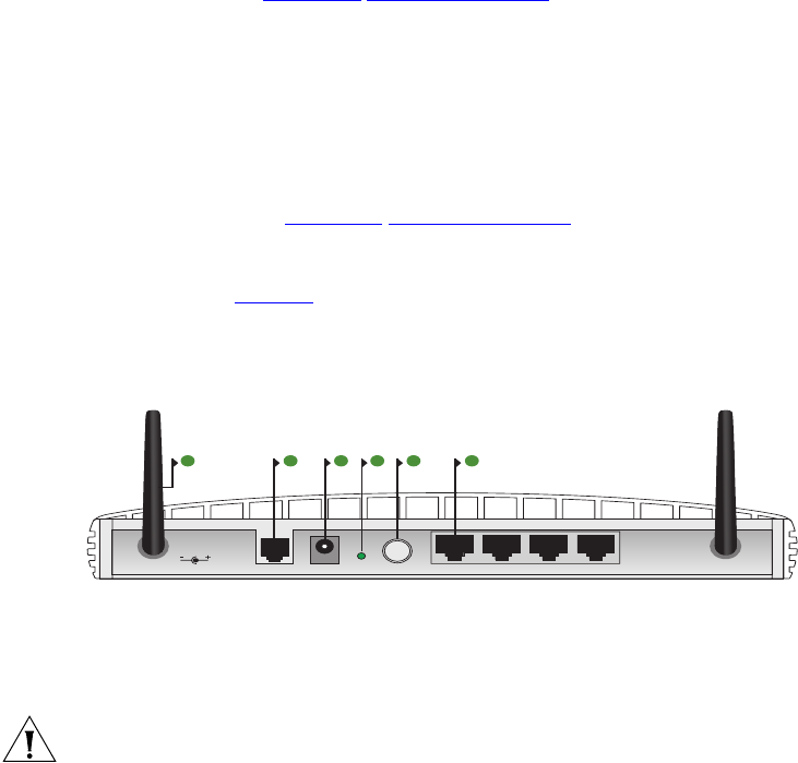
The rear panel (Figure 4) of the Router contains four LAN ports, one ADSL
port, a reset button, a power switch, and a power adapter socket.
Figure 4 Router - Rear Panel
6 Wireless Antennae
The antennae on the product should be placed in a ‘V’ position when
initially installed.
CAUTION: Do not force the antennae beyond their mechanical stops.
Rotating the antennae further may cause damage.
ADSL ResetPower LAN4 LAN3 LAN2 LAN1
12 VDC
1A MAX
7 98 11106

16 CHAPTER 1: INTRODUCING THE ROUTER
7ADSL Port
Using the RJ11 cable provided, you should connect your Router to the
telephone socket via a splitter.
8 Power Adapter Socket
Only use the power adapter that is supplied with this Router. Do not use
any other adapter.
9 Reset Button
If you want to reset your Router to factory default settings, and cannot
access the web management interface (for example, due to a lost
password), then you may use this button. Refer to “Forgotten Password
and Reset to Factory Defaults” on page 104 for further details.
10 Power Switch
Push this switch to the “in” position to turn the unit on. In the “out”
position, the unit is off.
11 Ethernet Ports
Using suitable RJ45 cables, you can connect your Router to a computer,
or to any other piece of equipment that has an Ethernet connection (for
example, a hub or a switch). These ports have an automatic MDI/MDIX
feature, which means either straight-through or a crossover cable can be
used.

2INSTALLING THE ROUTER
Introduction This chapter will guide you through a basic installation of the Router,
including:
■Connecting the Router to the Internet.
■Connecting the Router to your network.
■Setting up your computers for networking with the Router.
Safety Information Please note the following:
WARNING: Please read the “Safety Information” section in Appendix C
before you start.
VORSICHT: Bitte lesen Sie den Abschnitt “Wichtige Sicherheitshinweise”
sorgfältig durch, bevor Sie das Gerät einschalten.
AVERTISSEMENT: Veuillez lire attentivement la section “Consignes
importantes de sécurité” avant de mettre en route.
Positioning the
Router
You should place the Router in a location that:
■is conveniently located for connection to the telephone socket.
■is centrally located to the wireless computers that will connect to the
Router. A suitable location might be on top of a high shelf or similar
furniture to optimize wireless connections to computers in both
horizontal and vertical directions, allowing wider coverage.
■allows convenient connection to the computers that will be connected
to the four LAN ports on the rear panel, if desired.
■allows easy viewing of the front panel LED indicator lights, and access
to the rear panel connectors, if necessary.

18 CHAPTER 2: INSTALLING THE ROUTER
When positioning your Router, ensure:
■It is out of direct sunlight and away from sources of heat.
■Cabling is away from power lines, fluorescent lighting fixtures, and
sources of electrical noise such as radios, transmitters and broadband
amplifiers.
■Water or moisture cannot enter the case of the unit.
■Air flow around the unit and through the vents in the side of the case
is not restricted. 3Com recommends you provide a minimum of
25 mm (1 in.) clearance.
Using the Rubber
Feet
Use the four self-adhesive rubber feet to prevent your Router from
moving around on your desk or when stacking with flat top units. Only
stick the feet to the marked areas at each corner of the underside of your
Router.
Powering Up the
Router
To power up the Router:
1Plug the power adapter into the power adapter socket located on the
back panel of the Router.
2Plug the power adapter into a standard electrical wall socket.
3Press the power button located on the back of the Router.
Connecting the
Router
The first step for installing your Router is to physically connect it to the
telephone socket and then connect it to a computer in order to be able to
access the Internet. See Figure 5:
Connecting the Router 19
Figure 5 Connecting the Router
1Run the provided telephone cable from the wall jack providing ADSL
service to the ADSL port on your ADSL Router. When inserting an ADSL
RJ-11 plug, be sure the tab on the plug clicks into position to ensure that
it is properly seated. If you are using splitterless ADSL service, add
low-pass filters between the ADSL wall jack and your telephones. (These
filters pass voice signals through but filter data signals out.)
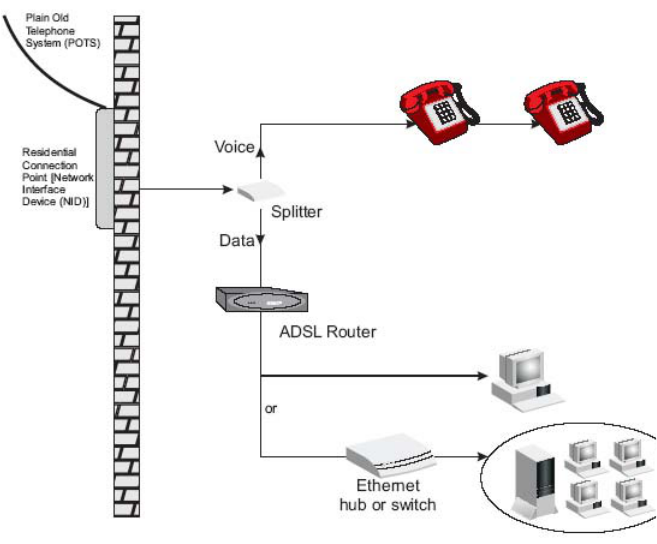
2Then:
■If you are using a full-rate (G.dmt) connection, your service provider
will attach the outside ADSL line to a data/voice splitter. In this case
you can connect your phones and computer directly to the splitter as
shown below (Figure 6):
or
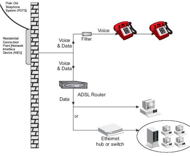
■If you are using a splitterless (G.lite) connection, then your service
provider will attach the outside ADSL line directly to your phone
system. In this case you can connect your phones and computer
directly to the incoming ADSL line, but you will have to add low-pass
filters to your phones as shown below (Figure 7)
Internet
Power
Supply Unit
Tele
p
hone
Socket
S
p
litter
/
Mi
c
r
o
fil
te
r Bl
ock
Y
ou
r P
C
Wir
e
l
ess
Use
r
s
3Com OfficeConnect
A
DSL Wireless 11
g
Firewall Route
r
20 CHAPTER 2: INSTALLING THE ROUTER
Figure 6 Installing with a splitter
Connecting the Router 21
Figure 7 Installing without a splitter
You have now completed the hardware installation of your Router. Next
you need to set up your computers so that they can make use of the
Router to communicate with the Internet.
3Com recommends that you perform the initial Router configuration
from a computer that is directly connected to one of the LAN ports.
If you configure the Router from a wireless computer, note that you may
lose contact with the Router if you change the wireless configuration.
To communicate wirelessly with your Router, your wireless NIC should be
set as follows:
■Encryption — none
■SSID — 3Com
■Channel — 11
22 CHAPTER 2: INSTALLING THE ROUTER

3SETTING UP YOUR COMPUTERS
The Router has the ability to dynamically allocate network addresses to
the computers on your network, using DHCP. However, your computers
need to be configured correctly for this to take place. To change the
configuration of your computers to allow this, follow the instructions in
this chapter.
Obtaining an IP
Address
Automatically
Windows 2000 If you are using a Windows 2000-based computer, use the following
procedure to change your TCP/IP settings:
1From the Windows Start Menu, select Settings > Control Panel.
2Double click on Network and Dial-Up Connections.
3Double click on Local Area Connection.
4Click on Properties.
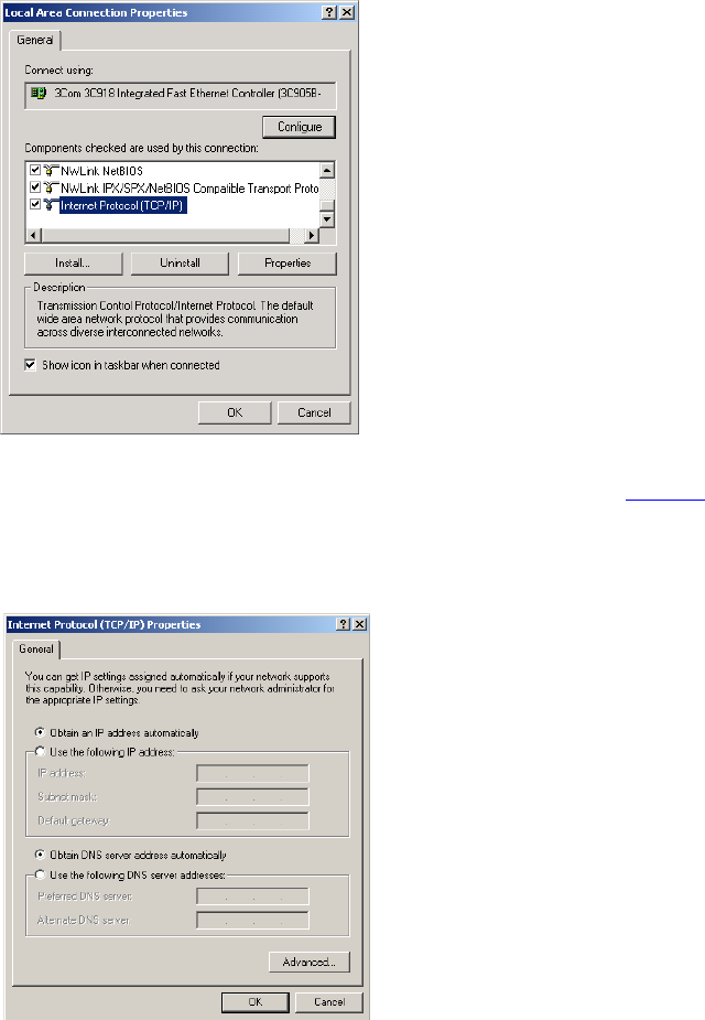
5A screen similar to Figure 8 should be displayed. Select Internet Protocol
TCP/IP and click on Properties.
24 CHAPTER 3: SETTING UP YOUR COMPUTERS
Figure 8 Local Area Properties Screen
6Ensure that the options Obtain an IP Address automatically, and Obtain
DNS server address automatically are both selected as shown in Figure 9.
Click OK.
Figure 9 Internet Protocol (TCP/IP) Properties Screen
7Restart your computer.
Obtaining an IP Address Automatically 25
Windows XP
1From the Windows Start menu, select Control Panel.
2Click on Network and Internet Connections.
3Click on the Network Connections icon.
4Double click on LAN or High Speed Connection icon. A screen titled Local
Area Connection Status will appear.
5Select Internet Protocol TCP/IP and click on Properties.
6Ensure that the options Obtain an IP Address automatically, and Obtain
DNS servers automatically are both selected. Click OK.
7Restart your computer.
Windows 98/ME
1From the Windows Start Menu, select Settings > Control Panel.
2Double click on Network. Select the TCP/IP item for your network card
and click on Properties.
3In the TCP/IP dialog, select the IP Address tab, and ensure that Obtain IP
address automatically is selected. Click OK.
Macintosh If you are using a Macintosh computer, use the following procedure to
change your TCP/IP settings:
1From the desktop, select Apple Menu, Control Panels, and TCP/IP.
2In the TCP/IP control panel, set Connect Via: to Ethernet.
3In the TCP/IP control panel, set Configure: to Using DHCP Server.
4Close the TCP/IP dialog box, and save your changes.
5Restart your computer.
26 CHAPTER 3: SETTING UP YOUR COMPUTERS
Disabling PPPoE
and PPTP Client
Software
If you have PPPoE client software installed on your computer, you will
need to disable it. To do this:
1From the Windows Start menu, select Settings > Control Panel.
2Double click on Internet Options.
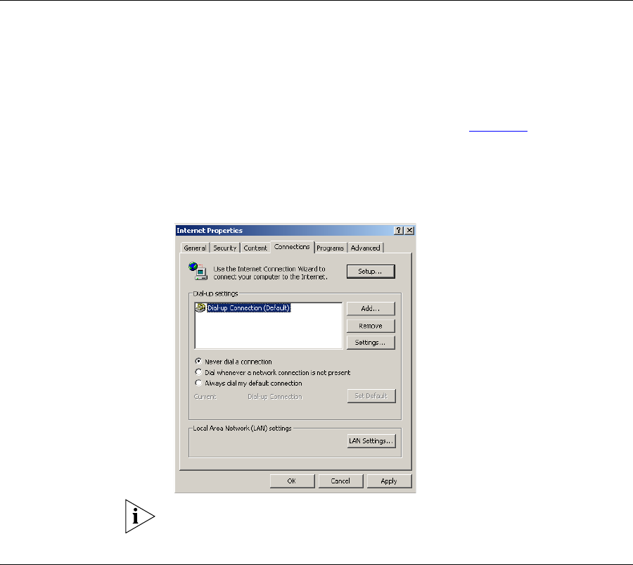
3Select the Connections Tab. A screen similar to Figure 10 should be
displayed.
4Select the Never Dial a Connection option.
Figure 10 Internet Properties Screen
You may want to remove the PPPoE client software from your computer
to free resources, as it is not required for use with the Router.
Disabling Web
Proxy
Ensure that you do not have a web proxy enabled on your computer.
Go to the Control Panel and click on Internet Options. Select the
Connections tab and click LAN Settings at the bottom. Make sure that
the Use Proxy Server option is unchecked.
4RUNNING THE SETUP WIZARD
Accessing the Setup
Wizard
The Router setup program is Web-based, which means that it is accessed
through your Web browser (Netscape Navigator 4.7 or higher, Internet
Explorer 5.0 or higher, or Mozilla 1.2.1 or higher).
To use the Setup Wizard:
1Ensure that you have at least one computer connected to the Router.
Refer to Chapter 2 for details on how to do this.
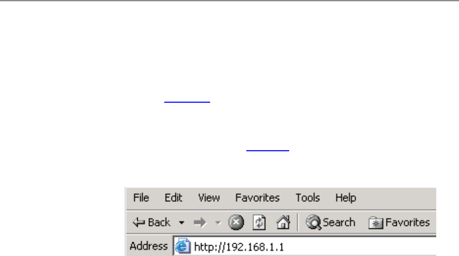
2Launch your Web browser on the computer.
3Enter the following URL in the location or address field of your browser:
http://192.168.1.1 (Figure 11). The Login screen displays.
Figure 11 Web Browser Location Field (Factory Default)
28 CHAPTER 4: RUNNING THE SETUP WIZARD
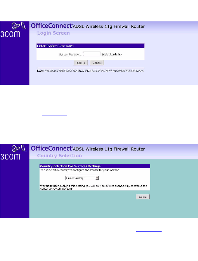
4To log in as an administrator, enter the password (the default password is
admin) in the System Password field and click Log in (Figure 12).
Figure 12 Router Login Screen
5When you have logged in,
■if you are logging in for the first time, the Country Selection screen
will appear (Figure 13). Please select the country form the drop-down
menu, and click Apply.
Figure 13 Country Selection Screen
The Wizard will then launch automatically (refer to Figure 16). You will be
guided step by step through a basic setup procedure.
■if the Router has been configured previously before, the Welcome
screen will appear (Figure 14). There are three tabs: Notice board,
Password, and Wizard.
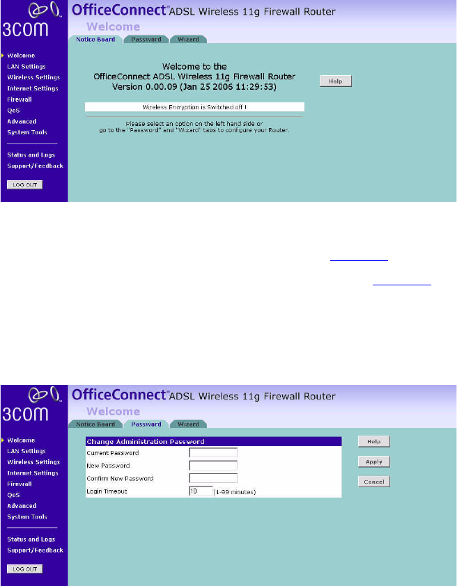
Accessing the Setup Wizard 29
Figure 14 Welcome Screen
■Go to the Notice Board tab to see the current software information. To
view the Web help, click the Help button.
■Go to the Password tab to change the password (Figure 15).
■Go to the Wizard tab to do a quick setup of the Router (Figure 16).
The password screen allows you to change the current password and set
the login time limit to the Router’s management interface.
Figure 15 Password Screen
1To change the current password, enter the password in the Current
Password field.
2Enter the new password in the New Password field, and enter it again in
the Confirm New Password field.
30 CHAPTER 4: RUNNING THE SETUP WIZARD
3Enter the time period in Login Timeout to set a maximum period of time
for which the login session is maintained during inactivity (Default: 10
minutes).
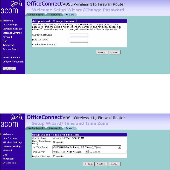
Setup Wizard -
Change Password
To ensure the security of your Router, it is recommended that you choose
a new password - this should be a mix of letters and numbers, and not
easily guessed by others. To leave the current password unchanged, leave
the fields blank and click Next.
Figure 16 Change Password Screen
Setup Wizard - Time
and Time Zone
The Time and Time Zone screen allows you to set up the time for the
Router.
Figure 17 Time and Time Zone Screen
1If you want to automatically synchronize the Router with a public time
server, check the Enable box in the Using Time Server field.
2Select the time zone in the Set Time Zone drop-down menu.
3Select the desired servers from the Time Server drop-down menu.
Accessing the Setup Wizard 31
4Check the Enable box in the Daylight Savings field, if daylight savings
applies to your area.
5Click Next.
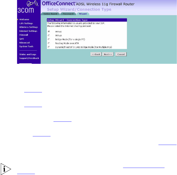
Setup Wizard -
Connection Type
The Connection Type screen allows you to set up the Router for the type
of Internet connection you have. Before setting up your connection type,
have your account information from your ISP ready.
Figure 18 Connection Type Screen
Select a DSL mode from the following:
■PPPoE — PPP over Ethernet, providing routing for multiple PCs, see
page 32
■PPPoA — PPP over ATM, providing routing for multiple PCs, see
page 33
■Bridge Mode (for a single PC) — RFC1483 Bridged Mode, for single
PCs only, see page 34
■Routing Mode over ATM — RFC1483 Routed Mode, for multiple PCs,
see page 34
■Dynamic/Fixed IP in 1483 Bridge Mode (for multiple PCs), see page 35
and click Next.
For further information on selecting a mode see “Internet Settings” on
page 54.
32 CHAPTER 4: RUNNING THE SETUP WIZARD
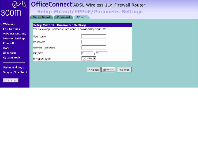
PPPoE Mode
To set up the Router for use with a PPP over Ethernet (PPPoE) connection,
use the following procedure:
Figure 19 PPPoE Screen
1Enter your user name in the Username field.
2Enter your password in the Password field.
3Re-type your password in the Retype Password field.
4Enter your VPI and VCI information in the VPI/VCI fields.
5Select the encapsulation type (LLC or VC MUX) in the Encapsulation
drop-down menu. This information should be provided to you by your ISP.
6Check all of your settings, and then click Next.
The LAN Settings screen will then be displayed (refer to Figure 24).

Accessing the Setup Wizard 33
PPPoA Mode
To set up the Router for use with a PPP over ATM (PPPoA) connection, use
the following procedure:
Figure 20 PPPoA Screen
1Enter your user name in the Username field.
2Enter your password in the Password field.
3Re-type your password in the Retype Password field.
4Enter your VPI and VCI information in the VPI/VCI fields.
5Select the encapsulation type (LLC or VC MUX) in the Encapsulation
drop-down menu. This information should be provided to you by your ISP.
6Check all of your settings, and then click Next.
The LAN Settings screen will then be displayed (refer to Figure 24).
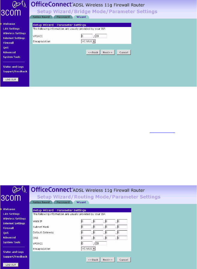
34 CHAPTER 4: RUNNING THE SETUP WIZARD
Bridge Mode (for a single PC)
To set up the Router for use with an RFC1483 bridged connection, use
the following procedure:
Figure 21 Bridged Mode Screen
1Enter your VPI and VCI information in the VPI/VCI fields.
2Select the encapsulation type (LLC or VC MUX) in the Encapsulation
drop-down menu. This information should be provided to you by your ISP.
3Check all of your settings, and then click Next.
The LAN Settings screen will then be displayed (refer to Figure 24).
Routing Mode over ATM
To set up the Router for use with an RFC1483 routed connection, use the
following procedure:
Figure 22 Routing Mode Screen