Arcadyan Technology WA8001BAC 4x4 Video bridge User Manual
Arcadyan Technology Corporation 4x4 Video bridge
UserManual.wiki
>
Arcadyan Technology
>
WA8001BAC User Manual
User Manual
Navigation menu
Upload a User Manual
Namespaces
Wiki Guide
HTML
PDF
Info
Views
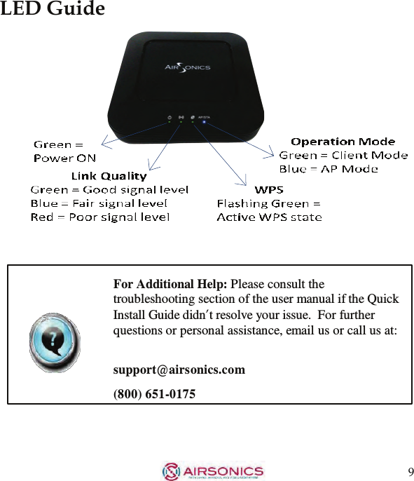
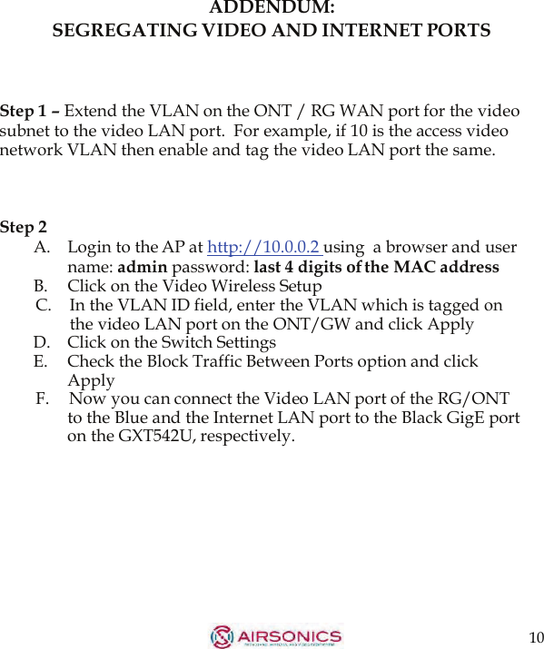
User Manual
Discussion / Help
Navigation