Arcadyan Technology WA8001BAC 4x4 Video bridge User Manual
Arcadyan Technology Corporation 4x4 Video bridge
User Manual
GXT542U Gigabit Wi-Fi Extender
QUICK INSTALL GUIDE
This guide will facilitate installation of the GXT 5G model
number GXT542U Gigabit Wi-Fi Extender which may be
co
nfigure
d
a
s
a:
• Multicast (IPTV) Video Bridge Access Point (AP)
(Section 1)
• Multicast (IPTV) Video Bridge Client (Section 2)
• Gigabit Wi-Fi AP (Section 3)
• Gigabit Wi-Fi Client (Section 4)
Prior to starting, ensure y
ou
have one ea
c
h:
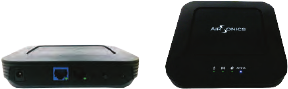
• GXT542U unit
• CAT5 Ethernet cable
• Power adapter
• Quick Installation Guide
2
MULTICAST (IPTV) VIDEO
B
RIDG
E
INSTALLAT
ION
Section 1
Multicast (IPTV) Video Bridge AP Installation
The initial GXT542U must be installed as an AP
Step 1 – Unit
Mode
Configuration
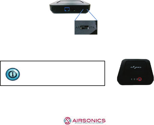
A. On the back of the device, set the unit mode switch to
A
P
(left position) as illustrated bel
ow
.
Step 2 –
Power
and LEDs
A. Plug in the 12V A/C adapter and connect it to the GXT542U
AP. Verify the
AP
/
STA LED
is
BLUE
indicating
AP
mode.
Changing the mode from AP (Blue)
to Client or Station (STA) (Green)
requires a power cycle.
Step 3 – Placement and
network
connections
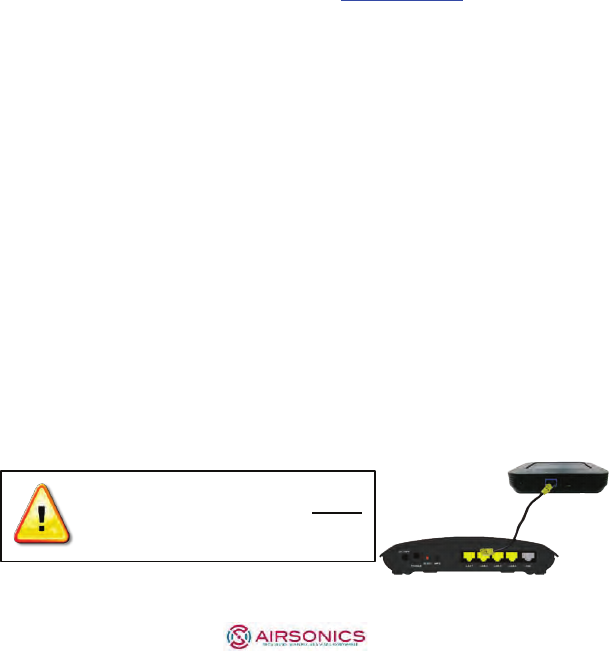
A. Place the GXT542U AP near the ONT/Residential Gateway
3
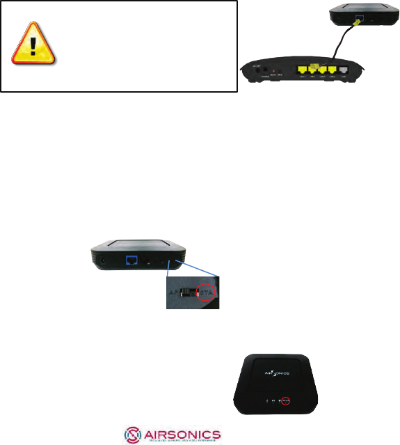
B. Insert one end of an Ethernet cable into the Video LAN port
of the ONT/ RG with the other to the GXT542U’s RJ-45 port.
Section 2
DO NOT connect both
Ethernet ports on the AP to the
same subnetwork ports on the
ONT/Gateway as this will
create a loop and disrupt
traffic.
Multicast (IPTV) Video Bridge Client Installation
After installing a GXT542U AP per Section 1, Clients can be added
using the steps below:
Step 1 – Unit
Mode
Configuration
A. Set the unit mode switch at the back of the unit to STA
(Right position) as illustrated below.
Step 2 -
Power
and LEDs
A. Plug in the 12V A/C adapter and connect it to the
G
XT5
42
U
STA unit. Verify the AP / STA LED is GREEN
indicating Client (STA) mode.
Home Gateway or
Cable/DSL Modem
4
Step 3 – Placement and
network
connections
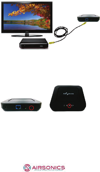
A. Place the GXT542U Client near the Multicast Video
S
et-
Top
Box (STB).
B. Insert the Ethernet cable into the STB and the other end into
one of the Ethernet ports of the GXT542U.
Step 4 – Pair the Client
with
theAP
A. Press the WPS button on the back of the GXT542U AP.
Th
e
WPS LED on the top front will flash for up to 2 minutes,
indicating it is ready for association with Clients.
B. Within 2 minutes, press the WPS button on the GXT542U
Client. The WPS LED will continue flashing until associated
with the
AP and
stop at which time the WLAN LED will
illuminate.
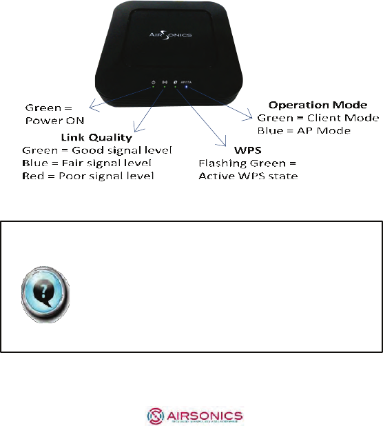
WPS Button WPS LED

5
Client
AP
The WLAN LED color indicates the receiver signal strength
(RSSI)
Green = Good, Blue = Fair, Red = Poor
Step 5 – Install the DVR and STBs
Congratulations. You have completed installation of a Gigabit Wi-Fi
Multicast IPTV link. Turn on any TV channel for visual verification of
the wireless connection quality.
Additional GXT542U clients can be paired to the AP
following the guideline in Section 2.
Step 6 – Verify the wireless performance
Access the Web User Interface to verify the wireless capacity for
watching and recording video.
A. Set all TV(s) to the highest resolution HD channels
B. Begin recording HD channels on the DVR (if installed)
C. Ensure the laptop Ethernet port is configured to a fixed IP
address of 10.0.0.50
6
D. Connect the PC to the AP via Ethernet, open a browser and
enter the AP’s default IP address http://10.0.0.2
to access the
GXT542U.
E. Login using user name: admin password: last 4 digits of the
MAC address (printed on the bottom of the
device)
F. Click on the System Information on the left
G. Ensure the Free Air Time is GREEN
H. Select Video Station List
I. Verify all the RSSI levels are GREEN or BLUE
GIGABIT Wi-Fi INTERNET ACTIVATION
AND
AP AND CLIENT IN
STALLAT
ION
Section 3
Activating the Gigabit Data Wi-Fi Network
By default, the GXT542U Internet Network and associated SSID are
not pre-configured.
Steps 1 and 2 – Refer to Section 1, Steps 1 and 2 instructions
on page 2 Multicast (IPTV) Video Bridge AP Installation.
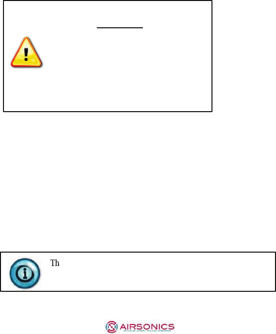
When Multicast Video (IPTV) and
Internet Data originate on the SAME
ONT/ RG port, connect the single
Ethernet port to the GXT542U.
Home Gateway or
Cable/DSL Modem
7
If Multicast Video (IPTV) and Internet Data
originate on SEPARATE ONT / RG ports,
refer to the instructions on the attached
addendum Segregating Video & Internet
Ports. The 2 GE GXT542U ports are factory
bridged and need to be reconfigured to
segregate these traffic types and eliminate
the potential for IP related issues.
Step 3 – Activate the Internet Wi-Fi Network
To login to the web Interface to create the Data Wi-Fi network:
A. Follow Section 2, Step 6 C – E directions to access the AP
web interface
B. Click on the Data Wireless Setup menu item on the left
C. Check the box and click Apply to enable the Data network
D. Confirm the screen displays the Data wireless network
Congratulations! You have activated and installed the Gigabit Wi-Fi
Internet network. Connect any 5 GHz 11ac or 11n device to the
Internet SSID using the passphrase below to access the internet.
e default passphrase for connecting to the Data Wi-Fi
Network is the last 8 digits of the AP’s MAC address printed
on the bottom.

8
SECTION 4
INSTALLING a Gigabit Wi-Fi Client
The GXT542U configured as a Client offers an ultra-high performance
Gigabit Wi-Fi connection to Gaming Consoles, SmartTVs and streaming
devices such as FireTV, Roku and Apple TV.
Steps 1 – 2
A. Follow the instructions outlined in Section 2, Steps 1 – 2
substituting the Smart TV, Gaming Console or streaming
device for the STB
Step 3 – Pairing the Client
with
theAP
A. Follow the instructions below for pairing the Client to the
Data Wireless Network
By default, the WPS function is associated with the Video Network. To
change the WPS capability to the Data Wireless Network, login to the
WEB User Interface to set up the Data Wi-Fi network as the default
WPS SSID.
A. Follow Steps 1 -3 in Section 3
B. Click on the Data Wireless Setup menu item on the left
C. Check the WPS Default option and click Apply
D. Follow the pairing instructions in Section 2 Step 4 to pair the Client
with the AP

10
ADDENDUM:
SEGREGATING VIDEO AND INTERNET
PORTS
Step 1 – Extend the VLAN on the ONT / RG WAN port for the video
subnet to the video LAN port. For example, if 10 is the access video
network VLAN then enable and tag the video LAN port the same.
Step 2
A. Login to the AP at http://10.0.0.2
using a browser and user
name: admin password: last 4 digits of the MAC address
B. Click on the Video Wireless Setup
C. In the VLAN ID field, enter the VLAN which is tagged
on
the video LAN port on the ONT/GW and click
A
pply
D. Click on the Switch Settings
E. Check the Block Traffic Between Ports option and click
Apply
F. Now you can connect the Video LAN port of the RG
/
ON
T
to the Blue and the Internet LAN port to the Black GigE port
on the GXT542U, respectively.
FCC Statement:
Federal Communication Commission Interference Statement
This equipment has been tested and found to comply with the limits for a Class B digital
device, pursuant to Part 15 of the FCC Rules. These limits are designed to provide
reasonable protection against harmful interference in a residential installation. This
equipment generates, uses and can radiate radio frequency energy and, if not installed
and used in accordance with the instructions, may cause harmful interference to radio
communications. However, there is no guarantee that interference will not occur in a
particular installation. If this equipment does cause harmful interference to radio or
television reception, which can be determined by turning the equipment off and on, the
user is encouraged to try to correct the interference by one of the following measures:
● Reorient or relocate the receiving antenna.
● Increase the separation between the equipment and receiver.
● Connect the equipment into an outlet on a circuit different from that to which the
receiver is connected.
● Consult the dealer or an experienced radio/TV technician for help.
FCC Caution: Any changes or modifications not expressly approved by the party
responsible for compliance could void the user’s authority to operate this equipment.
This device complies with Part 15 of the FCC Rules. Operation is subject to the following
two conditions: (1) This device may not cause harmful interference, and (2) this device
must accept any interference received, including interference that may cause undesired
operation.
This device and it's antennas(s) must not be co-located or operating in conjunction with
any other antenna or transmitter except in accordance with FCC multi-transmitter
product procedures.
This device is restricted for indoor use.
IMPORTANT NOTE:
FCC Radiation Exposure Statement:
This equipment complies with FCC radiation exposure limits set forth for an uncontrolled
environment. This equipment should be installed and operated with minimum distance
20 cm between the radiator & your body.