Arista Networks SS300ATC60 SpectraGuard Access Point / Sensor User Manual 6
AirTight Networks, Inc. SpectraGuard Access Point / Sensor Users Manual 6
Contents
- 1. Users Manual
- 2. Users Manual-1
- 3. Users Manual-2
- 4. Users Manual-3
- 5. Users Manual-4
- 6. Users Manual-5
- 7. Users Manual-6
- 8. (SS-300AT-C-60) UserMan-Part1_2013.12.11 revised
- 9. (SS-300AT-C-60) UserMan-Part2
- 10. (SS-300AT-C-60) UserMan-Part3
- 11. (SS-300AT-C-60) UserMan-Part4
- 12. (SS-300AT-C-60) UserMan-Part5
- 13. (SS-300AT-C-60) UserMan-Part6
Users Manual-6
Administration Tab
SpectraGuard® Enterprise User Guide
271
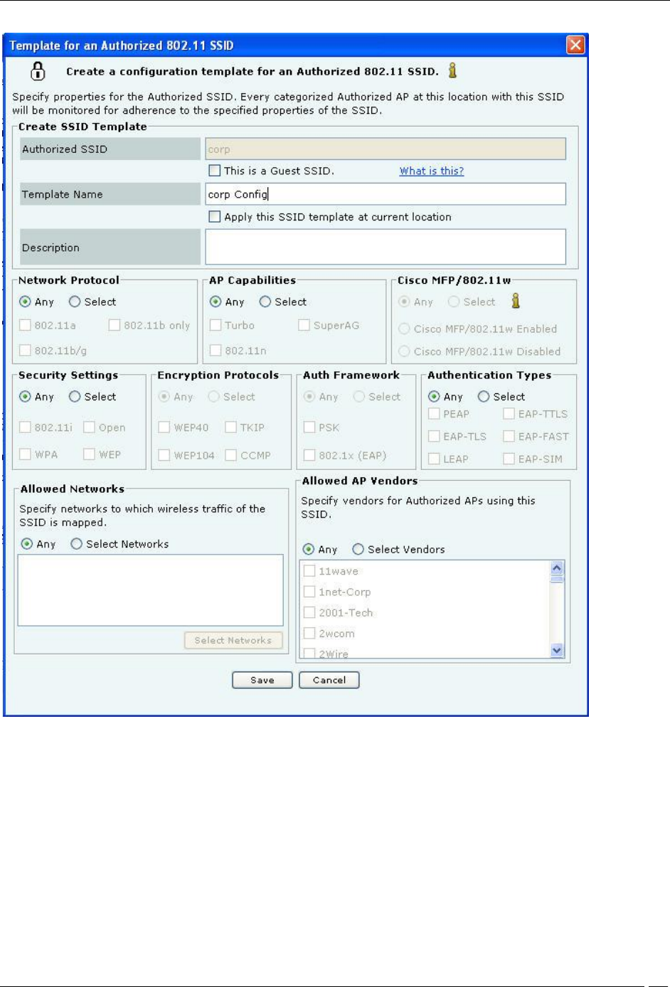
Creating a Configuration Template for an Authorized SSID
Create SSID Template allows you to specify the details for creating a new SSID as follows:
Authorized SSID: Displays the name of the SSID that you have added earlier
This is a Guest SSID: Select this option if this SSID is a Guest SSID used to provide Wi-Fi connectivity to
visitors and guests. Though APs with Guest SSID are Authorized, they may be treated differently than APs
that are used by employees for corporate access. Making an SSID as Guest allows you to specify additional
classification and prevention policies related to Guest SSIDs. Refer to the sections Client Auto-Classification
and Intrusion Prevention Policy for more details on classifying Guest SSIDs
Template Name: Name of the SSID template
Apply this SSID template at current location: Select this option to apply this SSID template to the
current location. The WLAN policy at a location consists of SSID templates applied at that location. If the
template is not applied at this location, it will not be a part of the WLAN policy

Administration Tab
SpectraGuard® Enterprise User Guide
272
Description: Write a short description to help identify the SSID template
Network Protocol allows you to select the allowed 802.11 protocols for the SSID:
Any: Allow APs with any network protocol for this SSID
Select: Specify the 802.11 protocol on which the system allows the APs connected to the network to
operate–802.11 a, 802.11 b/g, and 802.11b only
AP Capabilities allows you to select the additional capabilities that Authorized APs may have. If you select any
of these advanced capabilities, the classification logic allows APs with and without these capabilities. Select one of
the following:
Any: Allow APs with any special capability for this SSID
Select: Specify if the AP uses any Turbo/Super techniques used by Atheros to get higher throughputs–
Turbo, 802.11n, and SuperAG
Cisco MFP (802.11w) allows you to make classification decisions on Cisco Management Frame Protection(MFP)
capability if 802.11w checkbox is selected under Security Settings:
Any: Policy does not check for MFP; both Cisco MFP enabled and disabled APs are classified as
Authorized
Select: Policy checks for MFP
Cisco MFP Enabled: Select to classify only Cisco MFP supporting APs as Authorized APs
Cisco MFP Disabled: Select to classify non-Cisco MFP supporting APs as Authorized APs
Security Settings allows you to select the security protocol(s) for the SSID:
Any: Allow any security protocol for this SSID.
Select: Specify the exact security protocol(s) for this SSID from the list: 802.11i, WPA, Open, and WEP.
Encryption Protocols allows you to select encryption protocol(s) for the SSID:
Any: Allow any encryption protocol (including no encryption) for this SSID.
Select: Specify the exact encryption protocol(s) for this SSID from the list: WEP40, WEP104, TKIP, and
CCMP. Note that encryption protocols selection panel gets enabled only when WPA or 802.11i is selected.
Authentication Framework allows you to select authentication protocol(s) for the SSID:
Any: Allow any authentication protocol (including no authentication) for this SSID.
Select: Specify the exact authentication protocol(s) for this SSID from PSK and 802.1x (EAP). Note that
authentication protocols selection panel gets enabled only when WPA or 802.11i is selected.
Authentication Types allows you to select the allowed higher layer authentication types that Clients can use
while connecting to the SSID. Authentication types do not determine the classification of APs, but are used to raise an
event if a Client uses non-allowed authentication type. The system raises this event only if the system sees
authentication protocol handshake frames.
Any: Allow any higher layer authentication type for Clients connecting to this SSID.
Select: Specify the exact authentication type(s) that Clients can use (only if 802.1x is selected) from the
list: PEAP, EAP-TLS, LEAP, EAP-TTLS, EAP-FAST, and EAP-SIM.
Allowed Networks allows you to select the network(s) where wireless traffic on the SSID is to be mapped
through Authorized APs:
Any: Allow wireless traffic on this SSID to be mapped to any network.
Select Networks: Specify the exact networks where wireless traffic on this SSID is to be mapped through
Authorized APs. You can either choose from networks that are discovered automatically by the system or add
new networks that are not yet discovered by the system.
Click <Select Networks> to open Allowed Networks for SSID dialog where you can move a
network from Networks Monitored by the System to Allowed Networks for this SSID and add or
delete networks.
Under Allowed AP Vendors, select one of the following:
Any: Allow APs manufactured by any vendor to connect to the system.
Select Vendors: Select the manufacturer of the AP for the specified SSID.
SSID Templates
Administration Tab
SpectraGuard® Enterprise User Guide
273
A policy is collection of SSID templates attached to that location. You can apply an SSID template from the parent or
create it locally; if you wish to customize the WLAN policy for that location. Other templates may be available to be
attached but are not part of the WLAN policy and will not be used for AP classification.
The SSID Templates section lists the SSID templates that are available at a particular location. You must apply the
templates from the available list to create the WLAN policy at that location. A new AP or an existing Authorized AP
is compared against the applied SSID templates to determine if it is a Rogue or Mis-configured AP. The SSID
templates created at other locations can be applied to a selected location but cannot be edited or deleted. The edit and
delete operations are possible only at the location where the template is created. The table shows the following
details:
SSID: Name of the SSID
Guest SSID?: Indicates if it is a Guest SSID
Template Name: Name of the SSID template
Apply Here?: Enables you to apply the SSID template to the selected location. New and existing Authorized
APs are evaluated against all applied SSID templates to determine if they are Rogue or Mis-configured.
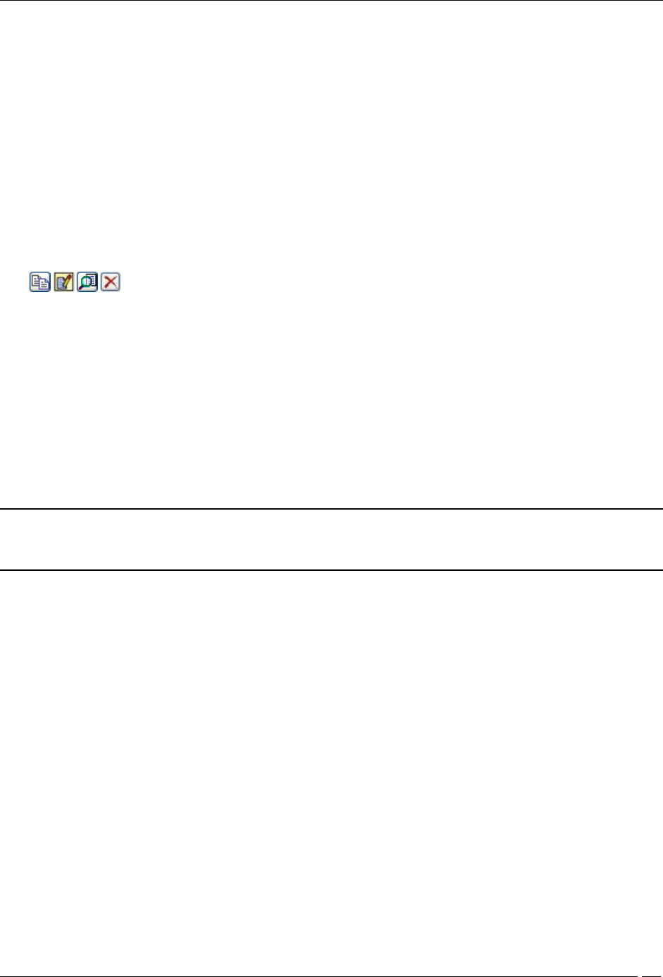
: Click these icons to perform the following:
Copy the selected SSID template to another location.
Edit the SSID template. This option is enabled only at the location where the template was created.
View the SSID template.
Delete the template. This option is enabled only at the location where the template was created and only
if the template is not applied at any other child locations of the location where it was created.
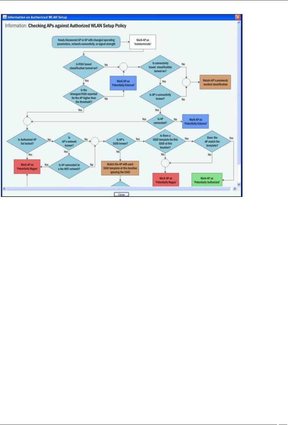
Determining Policy Compliance
An AP is considered as being compliant to the Authorized WLAN Policy if:
It is not connected to a No Wi-Fi network for its location
Its SSID matches with one of the templates attached at that location
Is connected to one of the networks specified in that template
Conforms to the other settings in that template (except the Authentication Framework, as this setting is not a
property of the AP itself but of the backend authentication system)
Note: If the template specifies certain allowed AP capabilities (such as Turbo, 802.11n, and so on.), the AP may or
may not have those capabilities. However, if a capability is not selected, the AP must not have that capability to be
considered as compliant.
With location-based policies, you can specify (or attach) different sets of SSID templates for different locations.
However, you cannot attach more than one template with the same SSID at any one location.
Administration Tab
SpectraGuard® Enterprise User Guide
274
Determining Policy Compliance
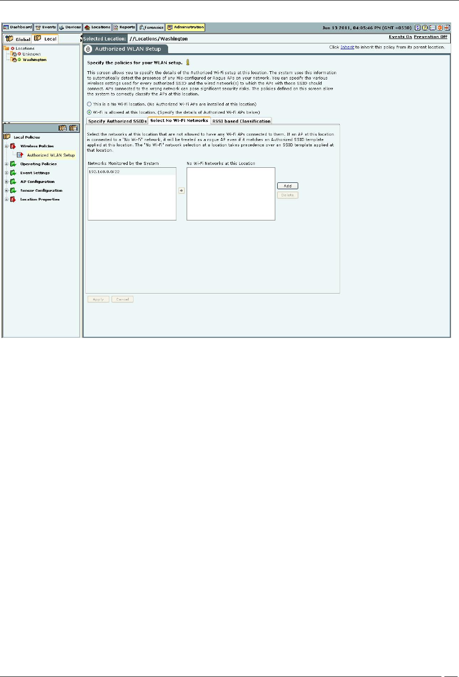
Select No Wi-Fi Networks
This section allows you to specify the list of networks at the selected location where no Wi-Fi APs are allowed to be
connected. The No Wi-Fi Networks list at a location takes precedence over the list of networks in SSID templates
applied at that location. In other words, if a network is included in a location’s no Wi-Fi list and happens to be in the
list of networks in one or more applied SSIDs at that location, the network will be still treated as a no Wi-Fi network.
Administration Tab
SpectraGuard® Enterprise User Guide
275
No Wi-Fi Network
Networks Monitored by the System: Specifies the networks monitored by the system.
No Wi-Fi Networks at this Location: Specifies the networks to which no Wi-Fi AP should be connected at the
selected location.
You can move a network from Networks Monitored by the System to No Wi-Fi Networks at this Location.
Click Add to enter a new network address to add a No Wi-Fi network at the selected location.
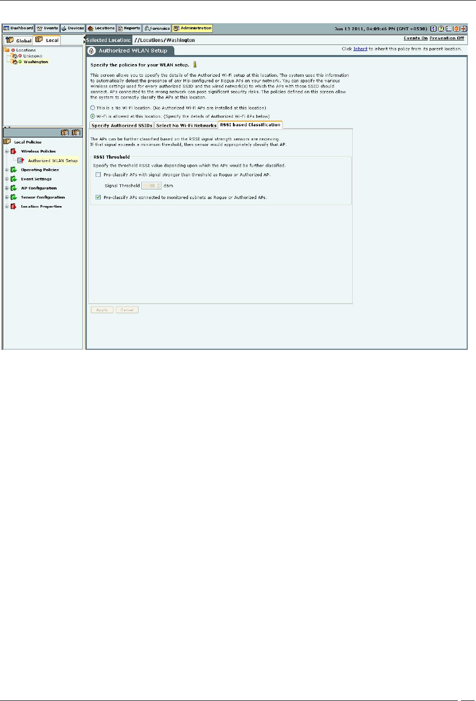
RSSI based Classification
APs are further classified based on the RSSI value that the sensors receive. If the signal strength exceeds a maximum
threshold, the sensor appropriately classifies the AP. Airtight higly recommends that you turn on network
connectivity based classification as it is the most reliable mechanism to classify wireless devices when most of your
network is monitored using sensors and NDs.
Under RSSI Threshold, select one or both (recommend) of the following checkboxes:
Pre-classify APs with signal strength stronger than threshold as Rogue or Authorized APs to specify the
threshold RSSI value based on which the system further classifies APs.
Pre-classify APs connected to monitored subnet as Rogue or Authorized APs to classify APs based on their
network connectivity.
Administration Tab
SpectraGuard® Enterprise User Guide
276
RSSI based Classification
Operating Policies
Select the Operating Policies screen to set the operating policies in the system. You can set the location-wise AP auto-
classification policy, client auto-classification policy, intrusion prevention levels and policy.
AP auto-classification
The AP Auto-Classification policy function enables you to specify the AP classification policy for different AP
categories.
Administration Tab
SpectraGuard® Enterprise User Guide
277
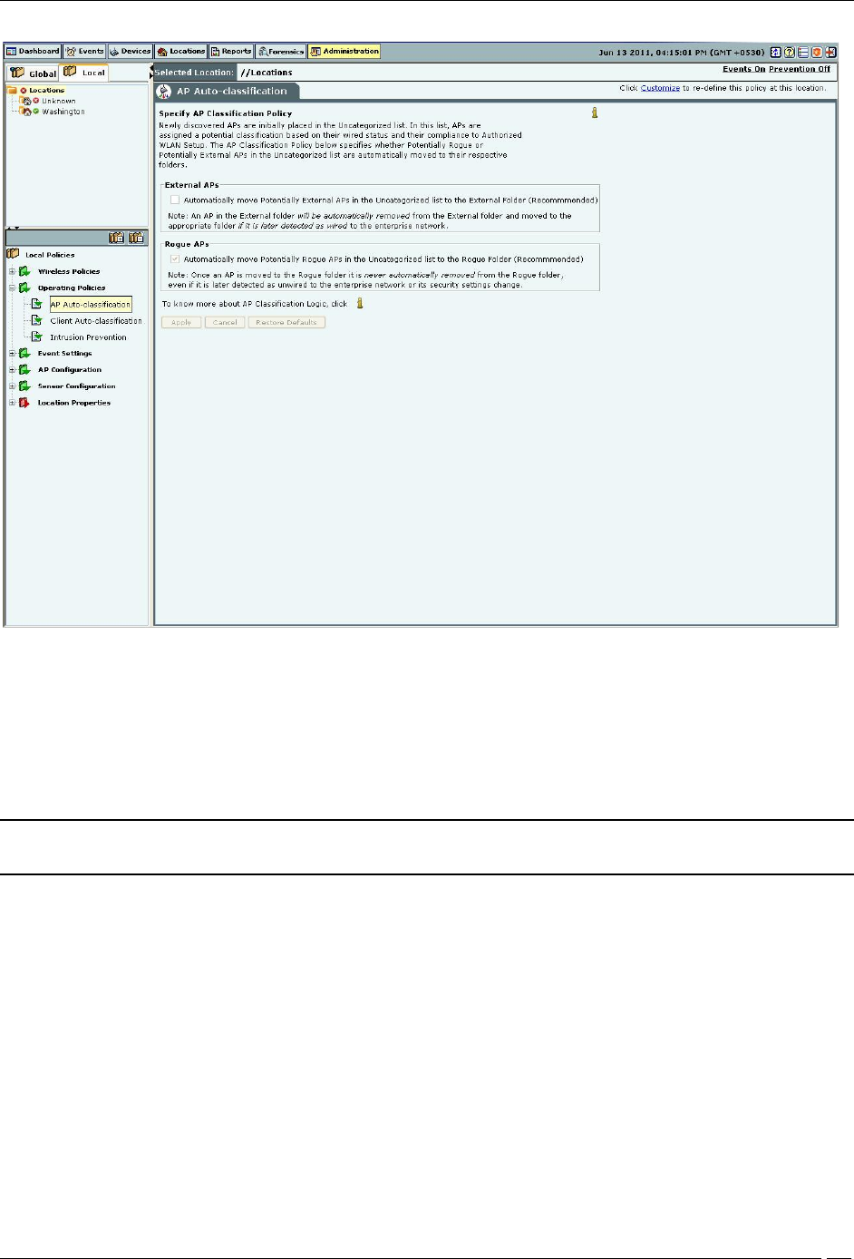
AP Auto-Classification Policy
Under External APs, AirTight recommends that you select Automatically move Potentially External APs in the
Uncategorized list to the External Folder. The system automatically removes an AP from the External folder and
moves it to an appropriate AP folder if it later detects that the AP is wired to the enterprise network.
Under Rogue APs, AirTight recommends that you select Automatically move Potentially External APs in the
Uncategorized list to the Rogue Folder.
Note: Once you move an AP to the Rogue folder, the system never automatically removes it from the Rogue folder,
even if it later detects that the AP is unwired from the enterprise network or its security settings have changed.
Client auto-classification
The Client Classification policy determines how Clients are classified upon initial discovery and subsequent
associations with APs.
Administration Tab
SpectraGuard® Enterprise User Guide
278
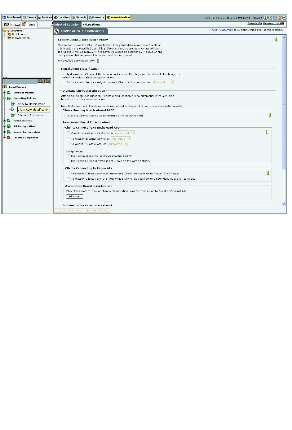
Client Auto-Classification Policy
Under Initial Client Classification, specify if newly discovered Clients at a particular location, which are
Uncategorized by default should be classified as External, Authorized or Guest.
Under Automatic Client Classification, select one or more options to enable the system automatically re-classify
Uncategorized and Unauthorized Clients based on their associations with APs. You can categorize the following
types of Clients.
Clients running SAFE
All External Clients running SpectraGuard SAFE are classified as Authorized
All Uncategorized Clients running SpectraGuard SAFE are classified as Authorized
All Rogue Clients running SpectraGuard SAFE are classified as Authorized
All Guest Clients running SpectraGuard SAFE are classified as Authorized
Clients connecting to Authorized APs
All External Clients that connect to an Authorized AP are re-classified as Authorized
All Uncategorized Clients that connect to an Authorized AP are reclassified as Authorized
All Guest Clients that connect to an Authorized AP are reclassified as Authorized
You can select the following Exceptions
Do not re-classify a Client connecting to a Mis-configured AP as Authorized
Do not re-classify a Client if its wireless data packets are not detected on the wired network (except if the
connection is reported by WLAN controller)
Clients connecting to Guest APs
All External Clients that connect to a Guest AP are reclassified as Guest
All Uncategorized Clients that connect to a Guest AP are reclassified as Guest
You can select the following Exceptions
Do not re-classify a Client connecting to a Mis-configured AP as Guest
Administration Tab
SpectraGuard® Enterprise User Guide
279
Do not re-classify a Client as Guest if its wireless data packets are not detected on the wired network
(except if the connection is reported by WLAN controller)
Clients connecting to External APs
All Uncategorized Clients that connect to an External AP are reclassified as External
All Uncategorized Clients that connect to a Potentially External AP are classified as External
All Guest Clients that connect to an External AP are re-classified as External
All Guest Clients that connect to a Potentially External AP are re-classified as External
Clients connecting to Rogue APs
All Clients other than Authorized Clients that connect to a Rogue AP are (re)classified as Rogue
All Clients other than Authorized Clients that connect to a Potentially Rogue AP are classified as Rogue
RSSI Based Classification
Enable RSSI based Client Classification
Uncategorized Clients
External Clients
RSSI threshold -60 dBm
Destination folder Authorized
Bridging to the Corporate Network
Classify any non-authorized Client as Rogue if it is detected as bridging wi-fi to the corporate network
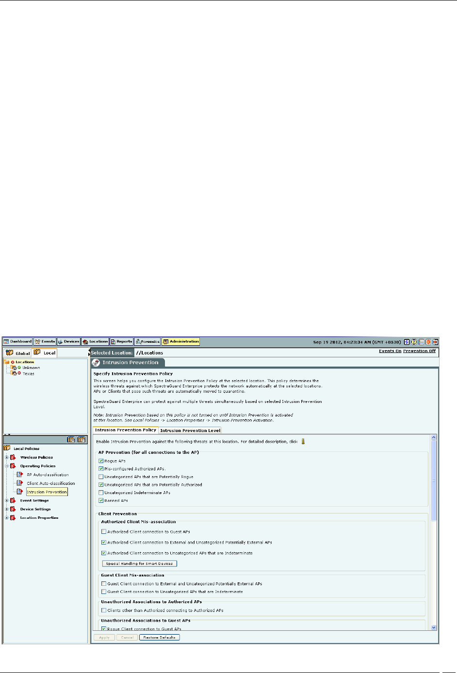
Intrusion Prevention Policy
The Intrusion Prevention Policy determines the wireless threats against which the system protects the network
automatically. The system automatically moves such threat-posing APs and Clients to quarantine. The system can
protect against multiple threats simultaneously based on the selected Intrusion Prevention level.
If the server quarantines an AP or Client based on the Intrusion Prevention policy, the Disable Auto-quarantine
option ensures that the system will not automatically quarantine this AP or Client (regardless of the specified
Intrusion Prevention policies).
Administration Tab
SpectraGuard® Enterprise User Guide
280
Intrusion Prevention Policy
You can enable intrusion prevention against the following threats:
Rogue APs: APs connected to your network but not authorized by the administrator; an attacker can gain access to
your network through the Rogue APs. You can also automatically quarantine Uncategorized Indeterminate and
Banned APs connected to the network.
Mis-configured APs: APs authorized by the administrator but do not conform to the security policy; an attacker
can gain access to your network through misconfigured APs. This could happen if the APs are reset, tampered with,
or if there is a change in the security policy.
Client Mis-associations: Authorized Clients that connect to Rogue or External (neighboring) APs; corporate data
on the Authorized Client is under threat due to such connections. AirTight recommends that you provide automatic
intrusion prevention against Authorized Clients that connect to Rogue or External APs.
There is a special intrusion prevention policy for the smart devices that are not approved. Even if a current client
policy restricts authorized clients from connecting to a guest AP, an unapproved smart device can still be allowed to
do so. One needs to explicitly allow or restrict unapproved smart devices from connecting to a guest AP.
Refer to the section Smart Device Detection in the Devices Tab chapter for more information.
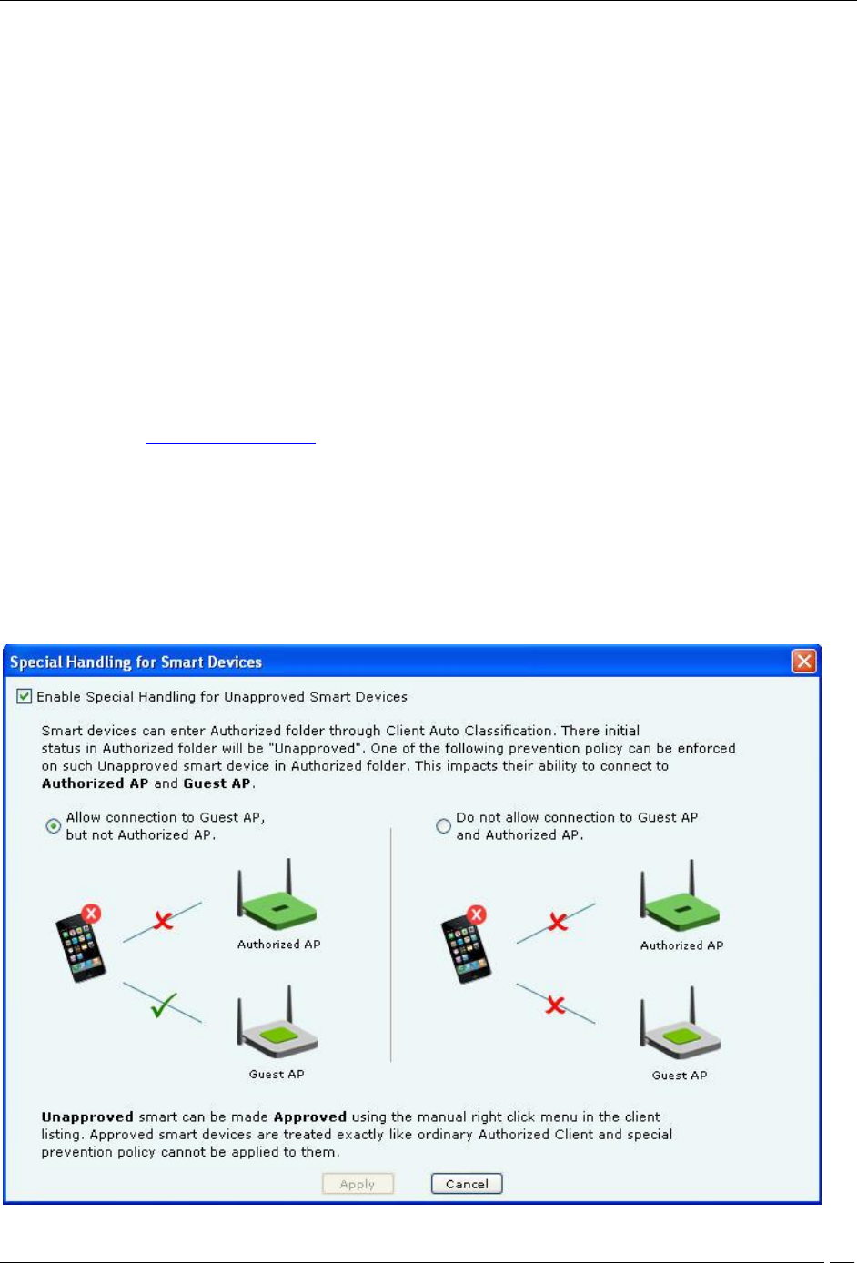
Click Special Handling for Smart Devices to enable special handling for unapproved smart devices. You can allow
the unapproved smart device to connect to a guest AP only. To do this,
1. Select Enable Special Handling for Unapproved Smart Devices.
2. Select Allow connection to Guest AP, but not Authorized AP.
To disallow the unapproved smart device from connecting to both a guest AP as well as an authorized AP, select Do
not allow connection to Guest AP and Authorized AP.

Administration Tab
SpectraGuard® Enterprise User Guide
281
Special Handling for Smart Devices
Non-authorized Associations: Non-authorized and Banned Clients that connect to Authorized APs; an attacker can
gain access to your network through Authorized APs if the security mechanisms are weak. Non-authorized or
Uncategorized Client connections to an Authorized AP using a Guest SSID are not treated as unauthorized
associations.
Associations to Guest APs: External and Uncategorized Clients that connect to Guest APs are classified as Guest
Clients. The Clients connected to a wired network or a MisConfigured AP can be specified as exceptions to this
policy.
Ad hoc Connections: Peer-to-peer connections between Clients; corporate data on the Authorized Client is under
threat if it is involved in an ad hoc connection.
MAC Spoofing: An AP that spoofs the wireless MAC address of an Authorized AP; an attacker can launch an
attack through a MAC spoofing AP.
Honeypot/Evil Twin APs: Neighboring APs that have the same SSID as an Authorized AP; Authorized Clients can
connect to Honeypot/Evil Twin APs. Corporate data on these Authorized Clients is under threat due to such
connections.
Denial of Service (DoS) Attacks: DoS attacks degrade the performance of an official WLAN.
WEPGuard TM: Active WEP cracking tools allow attackers to crack the WEP key and gain access to confidential
data in a matter of minutes or even seconds. Compromised WEP keys are used to gain entry into the authorized
WLAN by spoofing the MAC address of an inactive Authorized Client.
Client Bridging/ICS: A Client with packet forwarding enabled between wired and wireless interfaces. An
authorized Client bridging and unauthorized/uncategorized bridging Client connected to enterprise subnet is a
serious security threat.
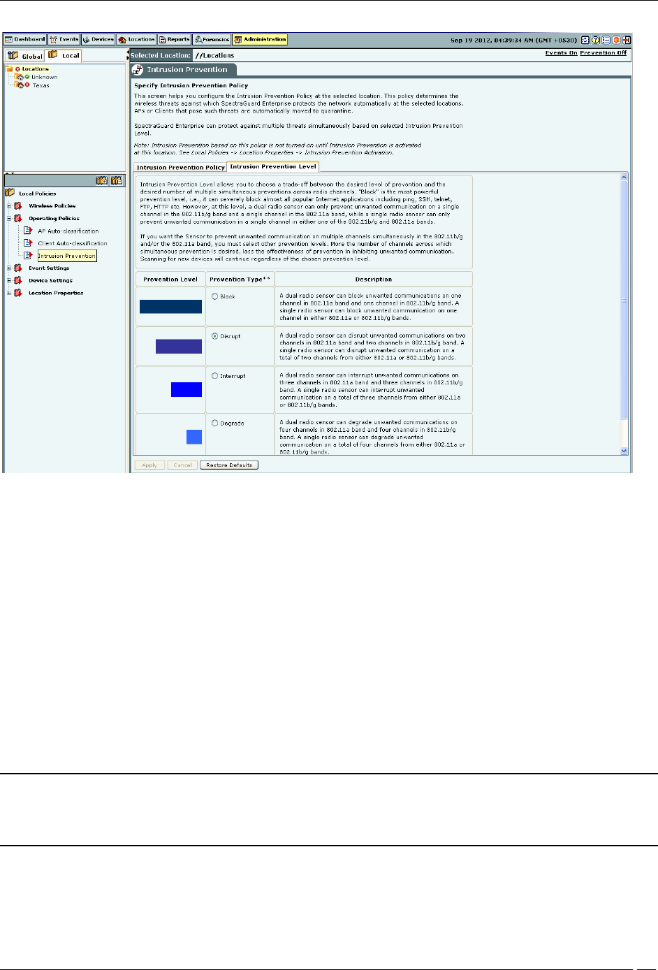
Intrusion Prevention Level
The system can prevent any unwanted communication in your 802.11 network. It provides you various levels of
prevention-blocking mechanisms of varying effectiveness. Intrusion Prevention Level enables you to specify a trade-
off between the desired level of prevention and the desired number of multiple simultaneous preventions across
radio channels.
The greater the number of channels across which simultaneous prevention is desired, the lesser is the effectiveness of
prevention in inhibiting unwanted communication. Scanning for new devices continues regardless of the chosen
prevention level.
Administration Tab
SpectraGuard® Enterprise User Guide
282
Intrusion Prevention Level
You can select the following prevention levels:
Block: A single sensor can block unwanted communication on any one channel in the 802.11b/g band and any
one channel in the 802.11a band.
Disrupt: A single sensor can disrupt unwanted communication on any two channels in the 802.11b/g band and
any two channels in the 802.11a band.
Interrupt: A single sensor can interrupt unwanted communication on any three channels in the 802.11b/g band
and any three channels in the 802.11a band.
Degrade: A single sensor can degrade the performance of unwanted communication on any four channels in
802.11b/g band and any four channels in the 802.11a band.
Block is the most powerful prevention level, that is, it can severely block almost all popular Internet applications
including ping, SSH, Telnet, FTP, HTTP, and the like. However, at this level, a single sensor can simultaneously
prevent unwanted communication on only one channel in the 802.11b/g band and one channel in the 802.11a band. If
you want the sensor to prevent unwanted communication on multiple channels simultaneously in the 802.11 b/g
and/or the 802.11a band, you must select other prevention levels.
Note: Prevention Type determines the blocking strength to prevent communication from unwanted APs and Clients.
The system can prevent multiple APs and Clients on each channel. Prevention Type is not applicable for Denial of
Service (DoS) attacks or ad hoc networks. You must select a lower blocking level to prevent devices on more channels.
Choosing a lower blocking level means that some packets from the blocked device may go through.
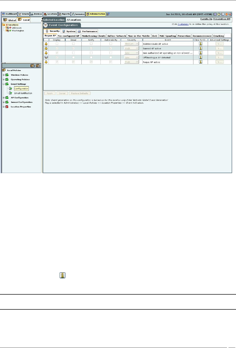
Event Settings
Configuration

Administration Tab
SpectraGuard® Enterprise User Guide
283
Event Configuration comprises of the following main tabs:
Security
System
Performance
Security
Security enables you to view events that indicate security vulnerability or breach in your network. Security events are
further divided into the following sub-categories:
Rogue AP
Mis-Configured AP
Misbehaving Clients
Prevention
DOS
Ad hoc Network
Man-in-the-Middle
MAC Spoofing
Reconnaissance
Cracking
Note: Prevention tab is not available with WIDS.
System
System enables you to view events that indicate system health. System events are further divided into the following
sub-categories:
Troubleshooting
Sensor
Server
Performance
Performance enables you to view events that indicate wireless network performance problems. Performance events
are further divided into the following sub-categories:
Bandwidth
Configuration
Coverage
Interference
Once you select an event type and then a sub-category, a list of events under that sub-category appears.
Administration Tab
SpectraGuard® Enterprise User Guide
284
Event Configuration
The events list displays the following columns:
Activity Status Icon: Specifies the activity status of the event – Live or Instantaneous.
Display: Select the checkboxes that correspond to the types of events that you want to appear in the main
Events screen.
E-mail: Select the checkboxes that correspond to the types of events for which you want email notifications sent
to all users whose email addresses you have configured in the AdministrationEvent SettingsEmail Notification.
Notify: Select the checkboxes that correspond to the types of events for which you want notifications sent to
external agents such as SNMP, Syslog, ArcSight, and OPSEC.
Vulnerability: Select checkboxes to indicate which types of events make the system Vulnerable. The Security
Scorecard shows Vulnerable status if any events of the selected type occur.
Severity: Select the severity of each event as High, Medium, or Low. This function helps you to organize events
in the most useful way.
Event: Provides a short description of each event.
Click for Details: Click to view a detailed description of the corresponding event category.
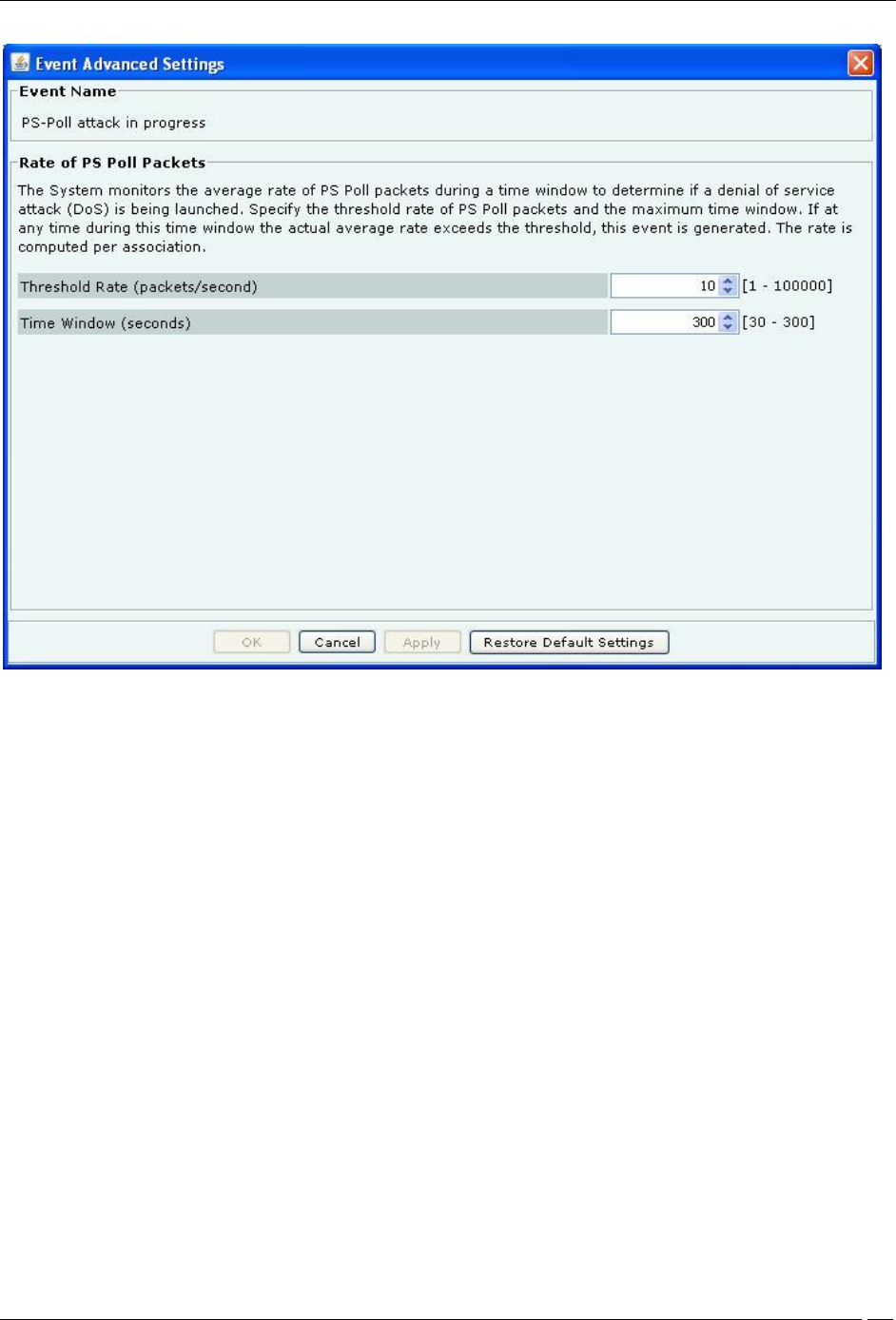
Advanced Settings: Click <Edit> to open the Event Advanced Settings dialog and change the configuration
parameters of the corresponding event category. <Edit> is disabled when the event has no configuration parameters.
Note: The parameters in the Event Advanced Settings dialog changes according to the settings for the selected
event.
Administration Tab
SpectraGuard® Enterprise User Guide
285
Event Advanced Settings
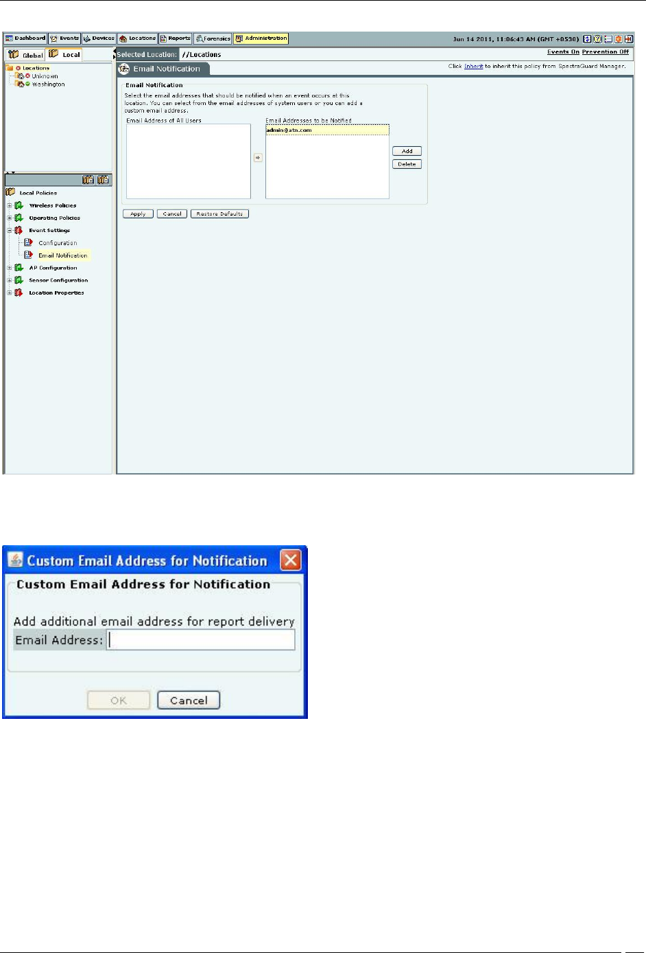
Email Notification
The Email Notification screen enables you to select the email addresses that should be notified when an event occurs
at a particular location. You can select from the email addresses of system users or add a new email address.
Administration Tab
SpectraGuard® Enterprise User Guide
286
Email Notification
Click Add to open Custom Email Address for Notification dialog where you can add a new email address.
Custom Email Addresses for Notification Dialog
Click OK to add the new email address.
Select an email address and click Delete to delete an existing email address. You can delete multiple email addresses
using click-and-drag or using the <Shift> + <Down Arrow> keys and then clicking Delete.
Device Settings
You can define the device templates and SSID profiles through Administration->Local->Local Policies->Device
Settings. Device templates can be applied to AirTight devices that function as WIPS sensors or as sensor/AP combos.
To define and manage SSID profiles, use the Administration->Local->Device Settings->SSID profiles.
To define and manage device templates, use Administration->Local->Device Settings->Device Template.
Administration Tab
SpectraGuard® Enterprise User Guide
287
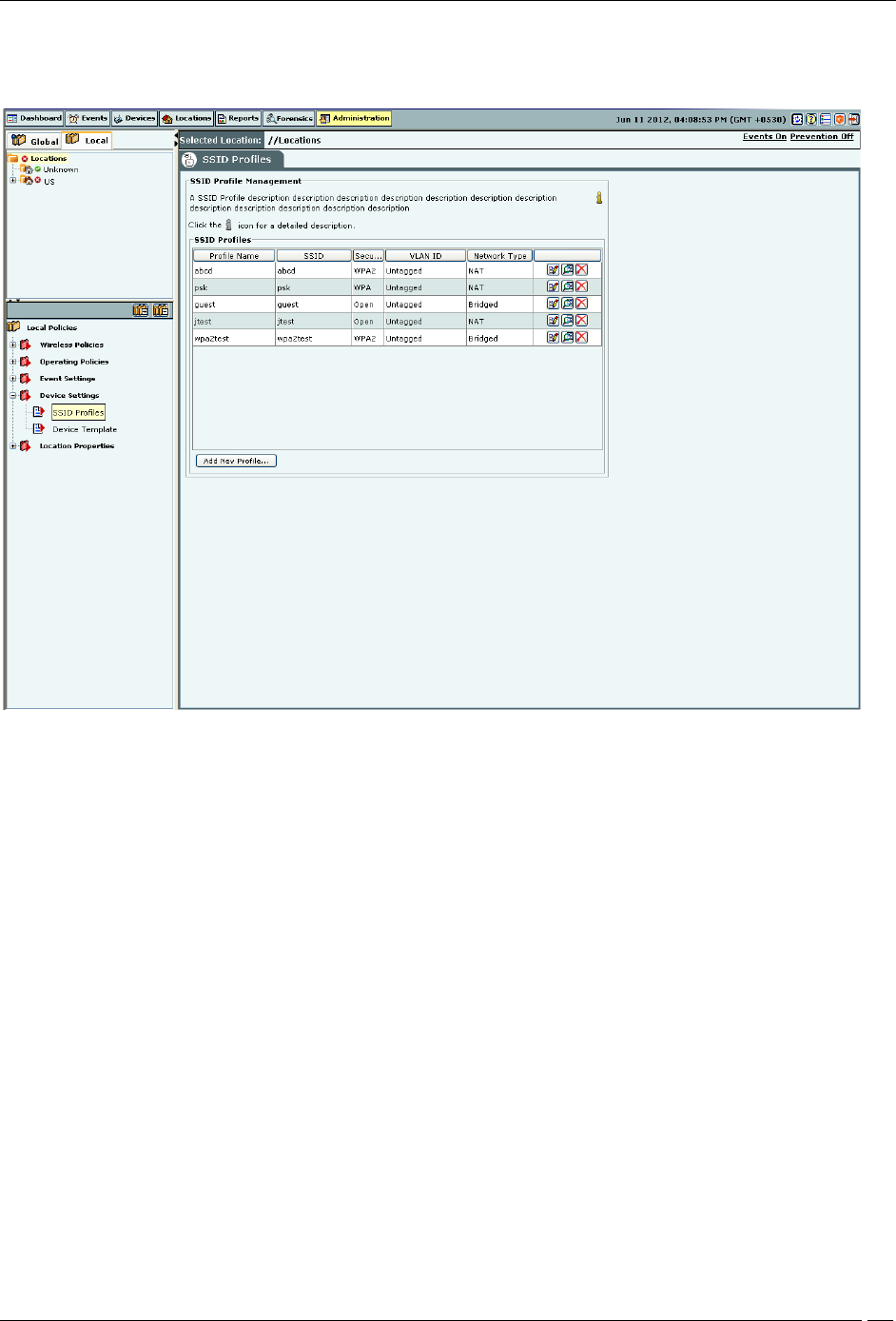
SSID Profile
Configure SSID Profiles using the SSID Profile.
SSID Profile
To add a wireless SSID profile, click Add New Profile. You can add multiple SSID profiles for the Sensor/AP combo
operating in the AP mode. When in AP mode, a single physical AP device can be logically split up into multiple
virtual AP's. Each wireless profile represents the configuration settings of a virtual AP. Multiple virtual APs can be
configured on a single radio. Up to 8 such virtual AP's can be configured using the Add New Profile dialog box.
To delete a profile from the list, select the respective row, and click Delete.
A virtual AP has the following features:
Each virtual AP supports Open, WPA (TKIP), WPA2 (CCMP) or WPA/WPA2 (TKIP+CCMP) security.
Distinct virtual AP's can have different security modes.
Each virtual AP can be used to provide distinct services that are independent of each other.
Data from the individual virtual AP’s can be assigned to a VLAN, so that data transmitted and received
over one virtual AP is not mixed with that over any other virtual AP. Thus, data from a virtual AP is not
visible outside that virtual AP.
The security settings for a virtual AP could be either of the following:
Open: Open means no security settings are to be applied. This is the default security setting.
WEP: WEP stands for Wireless Equivalent Privacy. WEP is a deprecated security algorithm for IEEE 802.11
networks. This has been provided for backward compatibility purpose only.

Administration Tab
SpectraGuard® Enterprise User Guide
288
WPA: WPA stands for Wi-Fi Protected Access. It is the security protocol that eliminates the shortcomings of
WEP.
WPA2: WPA2 is the latest and more robust security protocol. It fully implements the IEEE 802.11i standard.
WPA and WPA2 mixed mode: This stands for a mix of the WPA and WPA2 protocols.
PSK or Personal Shared key is generally used for small office networks. In case of bigger enterprise networks,
RADIUS authentication is used.
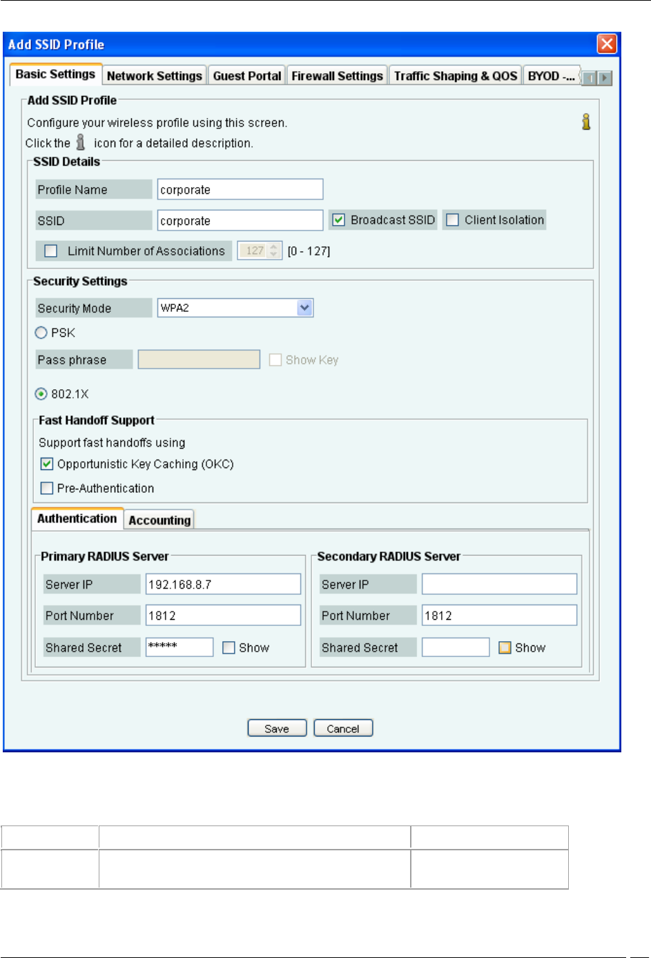
Basic Settings
The following dialog box appears on clicking Add New Profile.
Administration Tab
SpectraGuard® Enterprise User Guide
289
Basic Settings
The following table explains the fields present on the Basic Settings tab.
Field
Description
Default value
Profile Name
This field specifies the name of the profile.

Administration Tab
SpectraGuard® Enterprise User Guide
290
SSID
This field specifies the SSID of the wireless profile. This is a
mandatory field.
blank
Broadcast SSID
This check box indicates whether the SSID is to be broadcast
or not for this Virtual AP, in the beacon frames. If selected, the
beacon for this Virtual AP carries the SSID.
The check box is selected,
indicating that the SSID
is broadcast.
Client Isolation
This check box indicates whether communication between 2
wireless clients of this virtual AP is enabled or disabled. If
selected, wireless client communication is enabled for the
virtual AP.
The check box is clear,
indicating that wireless client
communication for the virtual
AP is disabled.
Limit number of
associations
This field specifies the maximum number of clients that can
associate with the AP. You can select the check box and then
specify the number of clients.
Security Mode
This specifies the security mode applied to the virtual AP.
The possible values are Open, WEP, WPA, WPA2, WPA and
WPA2 mixed mode.
Fields related to security mode WEP
Authentication
Type
Select Open if the type of authentication is open. In case of
open authentication, the key is used for encryption only.
Select Shared if the authentication type is shared key. In case
of shared key authentication, the same key is used for both
encryption and authentication.
Open
WEP Type
Select WEP40 if 40-bit WEP security is used.
Select WEP104 if 104-bit WEP security is used.
WEP104
Key Type
Select ASCII option if you are comfortable with ASCII format
and want to enter WEP key in that format. The Sensor/AP
combo converts it to hexadecimal internally.
Select HEX option if you are comfortable with hexadecimal
format and want to enter WEP key in that format.
ASCII
Key
WEP key is a sequence of hexadecimal digits.
If WEP Type is WEP40, enter the key as a 5 character ASCII
key or a 10 digit hexadecimal key, depending on the Key Type
selected by you.
If WEP Type is WEP104, enter the key as a 13 character
ASCII key or a 26 digit hexadecimal key, depending on the
Key Type selected by you.
blank
Show Key
Select this check box to see the actual key on the screen. If
this check box is cleared, the key is masked.
clear
Fields related to security mode WPA/WPA2/WPA and WPA2 Mixed Mode

Administration Tab
SpectraGuard® Enterprise User Guide
291
PSK
Select the PSK option if you want to use a personal shared
key. The Pass phrase field is enabled when this option is
selected.
PSK
Pass Phrase
Specify the shared key of length 8-63 ASCII characters for
PSK authentication
blank
Show Key
Select this check box to see the actual pass phrase on the
screen. If this check box is cleared, the key is masked.
clear
802.1x
Select 802.1x option if you want to use a RADIUS server for
authentication. The fields on the Authentication and
Accounting tabs are enabled on selecting this option.
clear
Opportunistic
Key Caching
Select the check box to enable client fast handoffs using
opportunistic key caching method. Note that the key caching
works within the same subnet only and not across subnets.
selected
Pre-
authentication
Select the Pre-Authentication check box to enable client fast
handoffs using the Pre-Authentication method.
clear
Fields in the Authentication Tab-Primary RADIUS Server area
Server IP
Enter the IP Address of the primary RADIUS server here.
blank
Port Number
Enter the port number at which primary RADIUS server listens
for client requests.
1813
Shared Secret
Enter the secret shared between the primary RADIUS server
and the AP.
blank
Show
Select this check box to see the actual text of the RADIUS
Secret on the screen. If this check box is cleared, the key is
masked.
clear
Fields in the Authentication Tab- Secondary RADIUS Server area
Server IP
Enter the IP Address of the secondary RADIUS server here.
blank
Port Number
Enter the port number at which secondary RADIUS server
listens for client requests.
1813
Shared Secret
Enter the secret shared between the secondary RADIUS
server and the AP.
blank
Show
Select this check box to see the actual text of the shared
secret on the screen. If this check box is cleared, the key is
masked.
clear
Field in the Accounting Tab
Enable RADIUS
Accounting
Select this check box to enable RADIUS Accounting. The
other fields on the Accounting tab are enabled on selecting
this check box. Define the primary RADIUS Server, and
optionally secondary RADIUS Accounting server in the
Accounting tab.
clear
Fields in the Accounting Tab- Primary Accounting Server area

Administration Tab
SpectraGuard® Enterprise User Guide
292
Server IP
Enter the IP Address of the primary accounting server here.
blank
Port Number
Enter the port number at which primary accounting server
listens for client requests.
1813
Shared Secret
Enter the secret shared between the primary accounting
server and the AP.
blank
Show
Select this check box to see the actual text of the shared
secret on the screen. If this check box is cleared, the key is
masked.
clear
Fields in the Accounting Tab- Secondary Accounting Server area
Server IP
Enter the IP Address of the secondary accounting server here.
blank
Port Number
Enter the port number at which secondary accounting server
listens for client requests.
1813
Shared Secret
Enter the secret shared between the secondary accounting
server and the AP.
blank
Show
Select this check box to see the actual text of the shared
secret on the screen. If this check box is cleared, the key is
masked.
clear
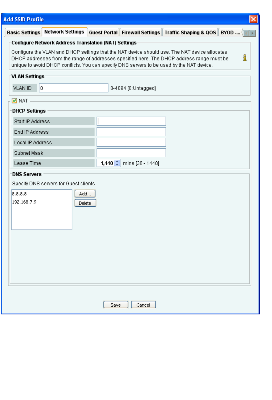
Network Settings
The following figure shows the fields on the Network Settings tab.
Administration Tab
SpectraGuard® Enterprise User Guide
293
Network Settings
Configure the VLAN and DHCP settings to be used be the NAT device using the Network Settings tab.
VLAN ID: Specify the VLAN ID.
Start IP address: Specify the starting IP address of the DHCP address pool in the selected network ID.
End IP address: Specify the end IP address of the DHCP address pool in the selected network ID.
Local IP address: Specify an IP address in selected network ID outside of the DHCP address pool. This address is
used as the gateway address for the guest wireless network.
Subnet Mask: Specify the netmask for the selected network ID.
Lease Time: Specify the DHCP lease time.
Administration Tab
SpectraGuard® Enterprise User Guide
294
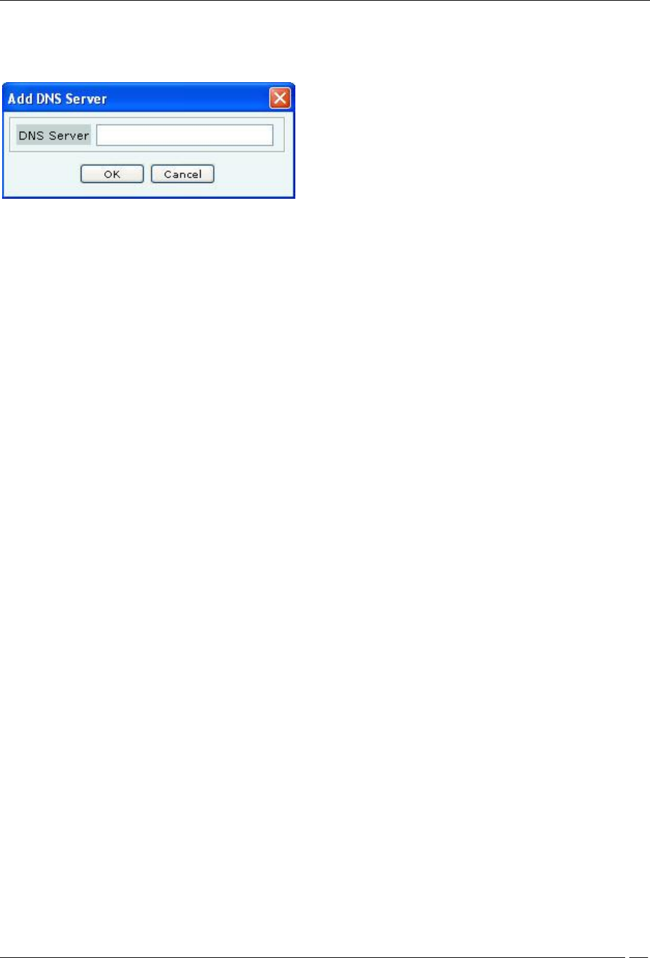
Guest clients will be allowed to make DNS queries to specific servers only. Specify at least one DNS server by
clicking Add.. under DNS Servers. The following screen appears on clicking Add..
Add DNS Server
You can specify up to three DNS server IP addresses. Requests to a DNS server, not specified under DNS Servers,
are dropped. Guest users cannot configure DNS servers of their choice. Using an external service like OpenDNS
allows control over what types of site are resolved and hence allowed for guests.
To delete a DNS server, select the entry and click Delete.
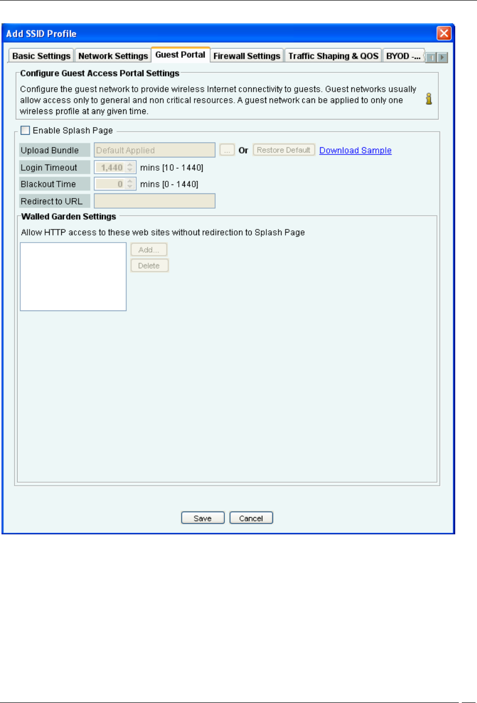
Guest Portal Settings
The following figure shows the fields on the Guest Portal tab.
Administration Tab
SpectraGuard® Enterprise User Guide
295
Guest Portal
A guest network is used to provide restricted wireless connectivity (e.g., Internet only) to guests. Currently ONLY
one wireless profile can be configured as a guest network.
Select Enable Splash Page to enable the splash page display.
The portal consists of a web page with a submit button. The portal supports only ‘click-through’; authentication is
not supported. The portal page can be used to display the terms and conditions of accessing the guest network as
well as any other information as needed.
Create a .zip file of the portal page along with any other files like images, style sheets etc. The zip file must satisfy the
following requirements for the portal to work correctly:
Administration Tab
SpectraGuard® Enterprise User Guide
296
The zip file should have a file with the name “index.html” at the root level (i.e., outside of any other folder). This is
the main portal page.
It can have other files and folders, (and folder within folders) at the root level that are referenced by the index.html
file.
The total unzipped size of the files in the bundle should be less than 100 KB. In case, large images or other content is
to be displayed on the page, this content can be placed on an external web server with references from the index.html
file. In this case, the IP address of the external web server must be included in the list of exempt hosts (see below).
The index.html file must contain the following HTML tags for the portal to work correctly:
A form element with the exact starting tag: <form method="POST" action="$action">
A submit button inside the above form element with the name “mode_login”. For example: <input type=”image”
name=”mode_login” src=”images/login.gif”>The exact tag: <input type="hidden" name="redirect" value="$redirect">
inside the above form element.
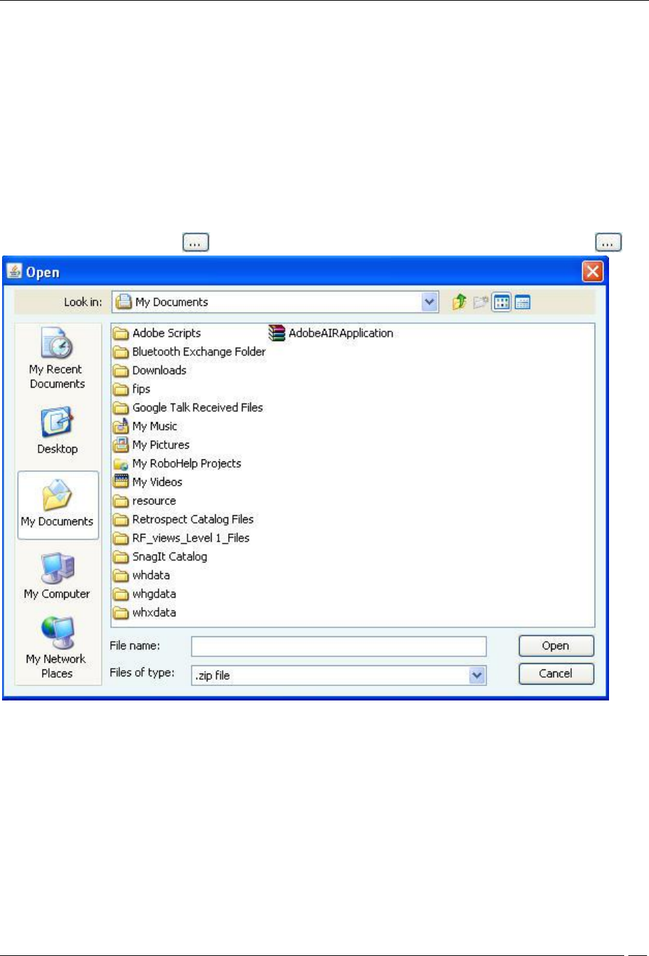
To upload the portal page, Click following Upload Bundle. The following dialog appears on clicking
Upload zip
To download the factory default portal bundle file, click Download Sample. This file can be used as a template for
creating a custom portal bundle file.
To restore the portal bundle to factory default file, click Restore Default.
Specify Login Timeout, in minutes, for which a wireless user can access the guest network after submitting the portal
page. After the timeout, access to guest network is stopped and the portal page is displayed again. The user has to
submit the portal page to regain access to the guest network.
Specify Blackout Time. This is the time for which a user is not allowed to login after his previous successful session
was timed out.
For example, if the session time-out is 1 hour and the blackout time is 30mins, a user will be timed out one hour after
a successful login. Now after this point, the user will not be able to login again for 30 minutes. At the end of 30
minutes, the user can login again.
Administration Tab
SpectraGuard® Enterprise User Guide
297
Specify the Redirect URL. The browser is redirected to this URL after the user clicks the submit button on the portal
page. If left empty, the browser is redirected to the original URL accessed from the browser for which the portal page
was displayed.
Walled Garden Settings: Configure a list of exempted IP address ranges. (E.g. 192.168.1.0/24) . HTTP and HTTPS
services on these IP addresses can be accessed without redirection to the portal page. If some part of the portal page
(e.g., images) is placed on a web server, the web server’s IP address must be included in this list for the content to be
successfully displayed.
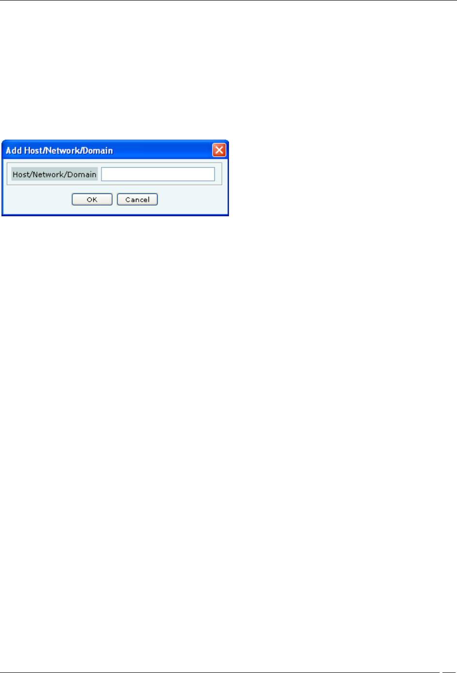
Click Add... under Walled Garden Settings to add the network/IP address of the exempted host. The following
screen appears.
Add Network Address
Enter the host or network address
To delete an exempted host IP address, select the entry and click Delete.
Firewall Settings
You can control the incoming and outgoing traffic for specific URLs by configuring firewall settings.
Administration Tab
SpectraGuard® Enterprise User Guide
298
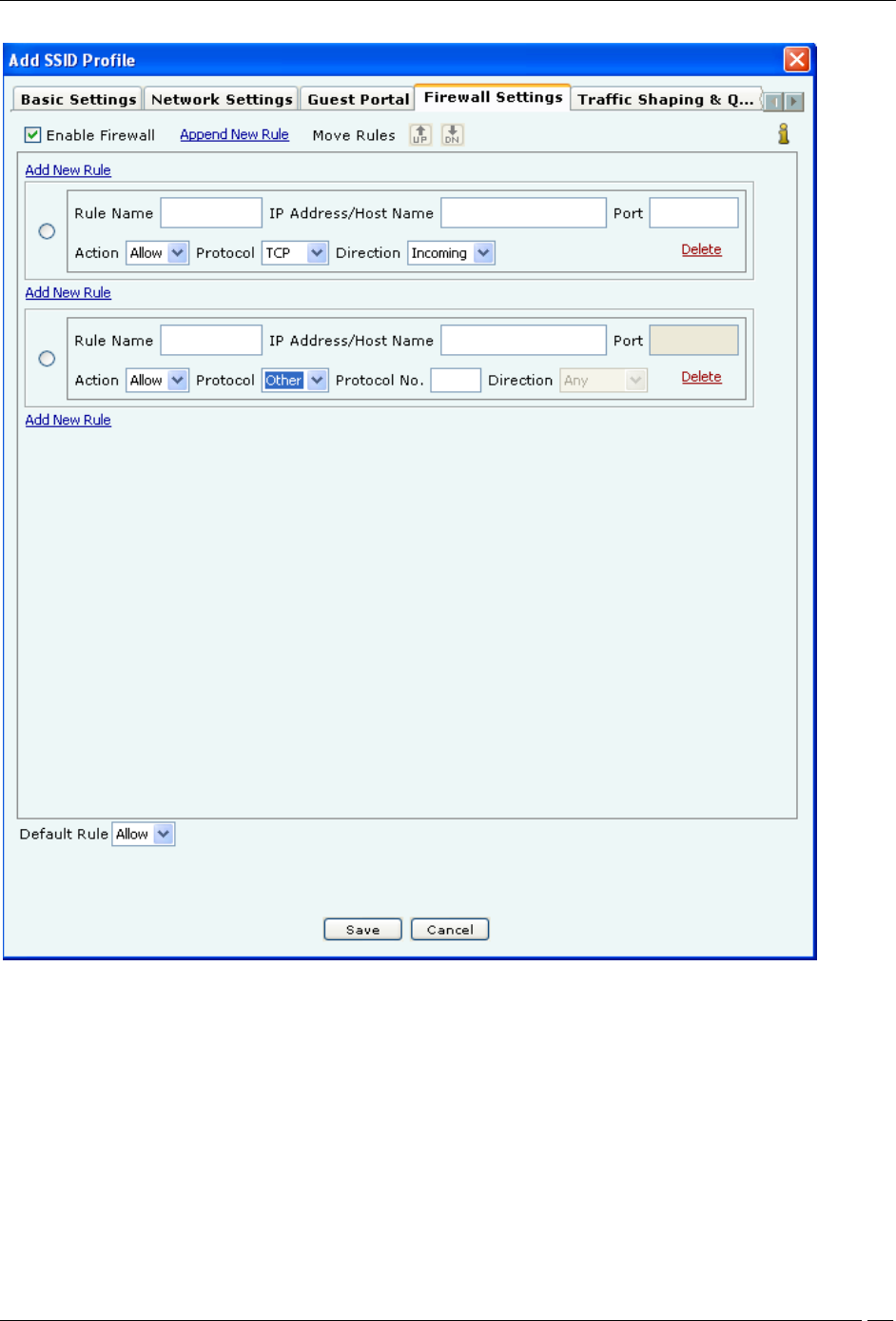
Firewall Settings
To enable firewall, select Enable Firewall. Click Append New Rule to add the first rule or a new rule at the end of
the existing rules. If you want to add a new rule between 2 rules, click Add New Rule between the 2 rules.
Specify the name of the rule in Rule Name, and the host name or IP address to which the rule applies in IP
Address/Host Name.
Specify the port number in Port. Specify the action Allow or Block. Specify the Protocol in Protocol. If you select
Protocol as Other, the field Protocol No appears, where you need to specify the protocol number. Specify whether
the action is to be applied to the incoming or outgoing request by selecting Incoming or Outgoing in Direction.
For example, if you want to block all outgoing TCP requests to the IP address 192.168.8.7 port 81, you will specify the
rule details as follows. Click Append New Rule or Add New Rule depending on where to want to add the rule.
Specify an appropriate name for the rule in Rule Name. Specify IP address/Host Name as 192.168.8.7, Port as 81,
Action as Block, Protocol as TCP, Direction as Outgoing.
Administration Tab
SpectraGuard® Enterprise User Guide
299
Define the default rule by selecting Allow or Block to allow or block any type of requests from IP addresses or host
names for which rules have not been defined.
Click Delete in the rule to delete the rule.
Traffic Shaping & QOS
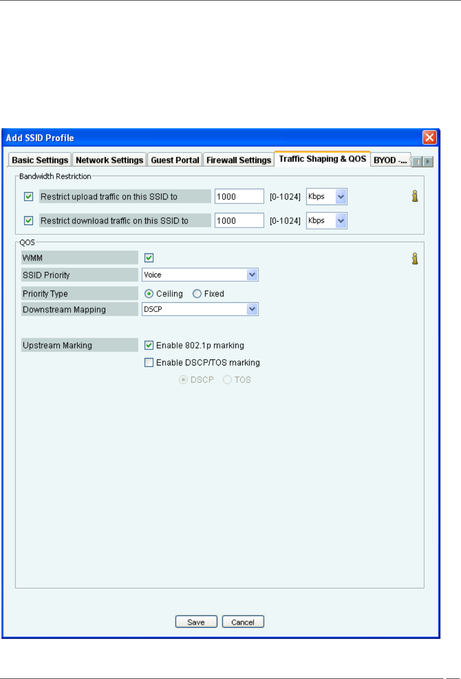
The values of the QoS parameters will depend on the type of applications that are used over the network. You can
specify the QoS parameters using the Traffic Shaping & QOS tab.
Traffic Shaping & QOS

Administration Tab
SpectraGuard® Enterprise User Guide
300
You can restrict the upload and download traffic on the SSID to a specific limit. Select Restrict upload traffic on this
SSID to and enter a value to restrict the upload traffic for the SSID.
Select Restrict download traffic on this SSID to and enter a value to restrict the download traffic for the SSID.
If you configure the radio in 11N mode, WMM (Wi-Fi multimedia) will always be enabled, irrespective of whether or
not you select the WMM check box, in the SSID profile. The reason for this behavior is that WMM is mandatory in
11N mode.
In 11N mode, if the WMM check box is not selected,the system uses the default QoS parameters. The system uses the
user-configured QoS settings if the WMM check box is selected.
Select the WMM check box and define your own QoS settings for Wi-Fi multimedia on the SSID profile.
Specify voice, video, best effort or background as the SSID Priority depending on your requirement.
Select Priority Type as Fixed if all traffic of this SSID has to be transmitted at the selected priority irrespective of the
priority indicated in the 802.1p or IP header.
Select Priority Type as Ceiling if traffic of this SSID can be transmitted at priorities equal to or lower than the
selected priority.
Select the Downstream mapping option if Priority Type is selected as Ceiling. The priority is extracted from the
selected field (802.1p, DSCP or TOS) and mapped to the wireless access category for the downstream traffic subject to
a maximum of the selected SSID Priority. For the downstream mappings, the mapping depends on the first 3 bits
(Class selector) of the DSCP value, TOS value or 802.1p access category. The only exception will be DSCP value 46
which will be mapped to WMM access category 'Voice'.
Select the Upstream marking option as per the requirement. The incoming wireless access category is mapped to a
priority subject to a maximum of the selected SSID priority and set in the 802.1p header and the IP header as selected.
Refer to the following table for the priority, 802.11e access category and the corresponding 802.1p access category and
DSCP value, used for upstream marking. If 802.1p marking is enabled, the 802.11e access category maps to the
corresponding 802.1p access category. If DSCP/TOS marking is enabled, the 802.11e access category maps to the
corresponding DSCP value.
Priority
802.11e access
category
802.1p access
category
DSCP
0
AC_BE (Best
Effort)
BK
(Background)
0
1
AC_BK
(Background)
BE(Best Effort)
10
2
AC_BK
(Background)
EE (Excellent
Effort)
18
3
AC_BE (Best
Effort)
CA (Critical
Apps)
0
4
AC_VI (Video)
VI(Video)
26
5
AC_VI (Video)
VO(Voice)
34
6
AC_VO(Voice)
IC(Internetwork
Control)
46
7
AC_VO(Voice)
NC(Network
Control)
48
BYOD- Device Onboarding
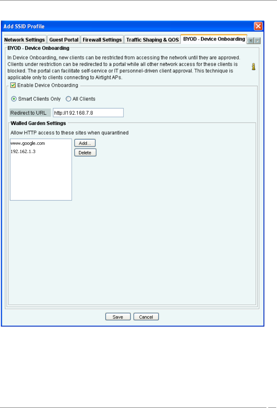
Device onboarding is a technique in which unapproved clients that are quarantined by the system are redirected to a
configured splash page URL upon making any web access while all other communication is blocked. This technique
can be enabled for all clients or selectively for smart clients only.
Administration Tab
SpectraGuard® Enterprise User Guide
301
BYOD - Device Onboarding
Select the Enable Device Onboarding check box to enable this technique.
Select Smart Clients Only if you want this technique to be enabled for unapproved smart client but not for other
wireless clients (like laptops etc.)
Select All Clients if you want to enable this technique for all types of unapproved wireless clients.
Specify the URL of the splash page in Redirect to URL. Wireless clients will be redirected to this URL upon making
any web request.
Administration Tab
SpectraGuard® Enterprise User Guide
302
The IP address or hostname of the splash page host must be added to the walled garden settings for the redirection to
work. Any other hostname or IP address that needs to be exempted from redirection can also be added here.
Use Add and Delete to modify the list of exempted hostnames or IP addresses.
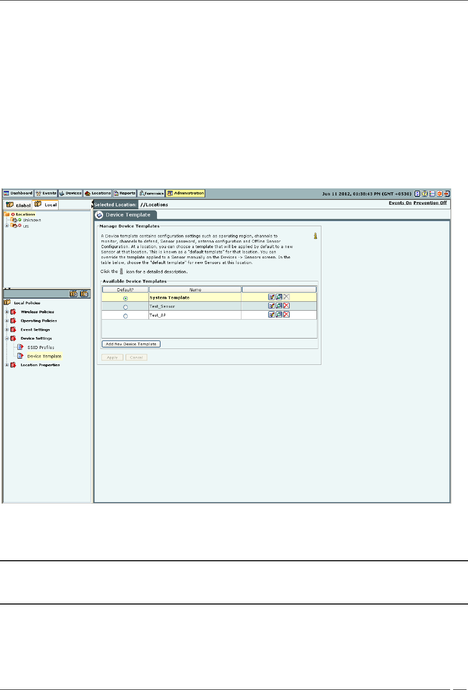
Device Template
You can create different templates to be applied to AirTight devices through this screen. A device template is a
combination of settings for radio, channels to monitor, VLANs to monitor, sensor configuration, antenna selection
and port assignment. This combination can be applied to an AirTight device such as a SS-300-AT-C-50, SS-30-AT-C-
60, SS-200-AT, SS-300-AT-C-10, SS-200-AT-01, or SS-300-AT.
The SS-300-AT-C-50 and SS-300-AT-C-60 sensor models can serve as a sensor/AP combo. This means that the SS-300-
AT-C-50 and SS-300-AT-C-60 sensor model can function as a WIPS sensor as well as an AP; all other sensor models
can function as WIPS sensors only.
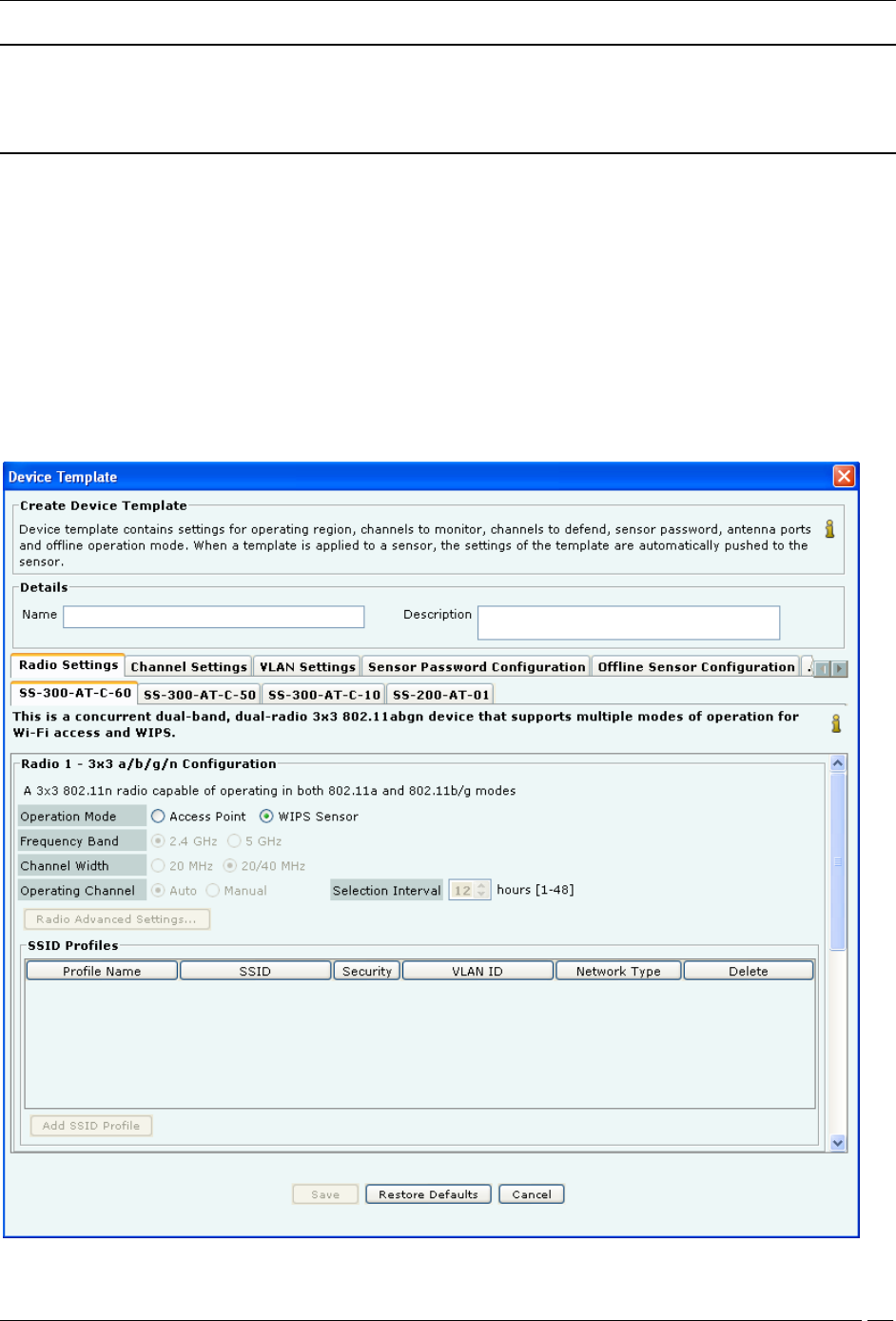
Device Template
You can choose a template as a default template, for a location. This template will be applied to any new sensor tagged
to that location.
Note: Sensors prior to Version 5.2 do not support additional channels (802.11j & Turbo channels), Sensor
Password Configuration, Offline Sensor Configuration, and Antenna Port Assignment features. If you apply
templates containing these settings to older sensors, older sensors will ignore the additional settings.
Click Add New Device Template to add a new device template.
Under Create Device Template, specify the following:
Name: Unique name of the device template (less than 40 characters)
Description: Brief description of the device template (less than 500 characters)
Administration Tab
SpectraGuard® Enterprise User Guide
303
Note: The system stores the default device configuration in a predefined template System Template. You cannot
delete the System Template nor edit its name; it is unique. When a device is added or discovered, it is automatically
assigned the configuration settings in this template. You are allowed to edit the configuration settings in the System
Template to effect default configuration of your choice.
Whenever you delete a user-defined device template, all the sensors associated with that template are assigned the
System Template. You can override the template applied to a sensor manually from the Devices Sensors tab. If you
modify the settings in a template, the new settings are applied to the sensors to which this template is applied.
On every tab in Device Template, you will find the Save, Restore Defaults and Cancel buttons.
You can navigate from one tab to another without saving the changes and save the changes made on all tabs by
clicking Save on any one tab.
Radio Settings
You can define radio settings for SS-300-AT-C-60 and SS-300-AT-C-50 if you want to configure them as access points.
The other devices function as WIPS sensors only.
Radio Settings-SS-300-AT-C-60

Administration Tab
SpectraGuard® Enterprise User Guide
304
When you select operation mode as Access Point, the other fields on the SS-300-AT-C-60 tab get enabled. In case the
operation mode is WIPS sensor, these fields remain disabled.
SS-300-AT-C-60 has 2 radios. You can separately configure the 2 radios, Radio 1 and Radio 2. You can add multiple
SSID profiles to be monitored by the SS-300-AT-C-60 devices operating in AP mode.
The following table describes the fields related to Radio Settings.
Field
Description
Applicable to frequency
band
Operation Mode
This field specifies whether the device functions as an
access point or a WIPS sensor. Select access point if you
want the device to function as an access point. Select
WIPS sensor if you want the device to function as a
sensor. This field is enabled only for SS-300-AT-C-60
and SS-300-AT-C-50 devices. The other 2 devices can
function as WIPS sensors only.
NA
Frequency Band
This field specifies the radio frequency band. The
possible values are 2.4 GHz, 5GHz. default value is 2.4
GHz
-
Channel Width
This field specifies radio channel width. Possible values
are 20 MHz or 20 Mhz/40Mhz.
For 2.4 GHz and 5GHz modes,
the channel width defaults to
20MHz.
Operating
Channel
This field specifies the operating channel for the radio.
By default, the AP selects the operating channel
automatically. (Auto is selected, by default.) User can
manually set the channel if desired. Select Manual, to
set the operating channel manually. The channel list
presented for manual channel selection, is populated
based on the location selected in the left pane. If the
manually selected channel is not present in the country of
operation selected for the device in the applied AP
template, the AP falls back to auto mode and selects a
channel automatically.
All
Selection Interval
This field is visible and available when the Operating
Channel is Auto. This field specifies the time interval, in
hours, at which the channel selection happens. You may
enter any value between 1 and 48, both inclusive.
All
Channel Number
This field is visible and available when the Operating
Channel is Manual. This field specifies the operating
channel number.
Fragmentation
Threshold
This field specifies the Fragmentation Threshold, in
bytes. Permissible value for this field is between 256 and
2346 bytes (both inclusive).
This field is applicable to
5GHz and 2.4 GHz modes.
RTS Threshold
This field specifies the threshold for Request to Send
(RTS) in bytes. Permissible value for this field is between
256 and 2347 bytes (both inclusive). Default value is
2347 bytes.
This field is applicable to 5 GHz
and 2.4 GHz modes.
Beacon Interval
This field specifies the time interval between AP beacon
transmissions. The value is set to 100. It is not editable.
DTIM Period
The DTIM period specifies the period after which clients
connected to the AP should check for buffered data
waiting on the AP. The value is set to 1. It is not editable.
Custom Transmit
Power
This field enables you to control the transmission power
of the AP. Select the custom transmit power check box
and specify the transmission power of the AP in dBM.
Enable
Background
Scanning
Select this check box to enable background scanning by
the device.
802.11n Guard
Interval
A period at the end of each OFDM symbol allocated to
letting the signal dissipate prior to transmitting the next
signal. This prevents overlaps between two consecutive
symbols. Legacy 802.11a/b/g devices use 800ns GI. GI of
400ns is optional for 802.11n
This field is 802.11n specific.

Administration Tab
SpectraGuard® Enterprise User Guide
305
Frame
Aggregation
This field specifies the enabling or disabling of MPDU
aggregation
This field is 802.11n specific.
When in AP mode, a single physical AP device can be logically split up into multiple virtual AP's. Each wireless
profile represents the configuration settings of a virtual AP. Click Add New Profile to select the SSID profiles for the
AP. Each SSID profile corresponds to a virtual AP. Upto 8 virtual APs can be configured on one radio.
Similar settings apply to SS-300-AT-C-50. SS-300-AT-C-50 has a single radio. It can be configured to work as an AP or
as a WIPS sensor.
SS-300-AT-C-10 and SS-200-AT-01 can function as WIPS sensors only. Hence fields related to radio settings are
disabled on these tabs.
Channel Settings
Channel Settings displays the 802.11a/802.11b/g and Turbo channels on which scanning and defending is
enabled/disabled. Sensors scan WLAN traffic on channels specified under Channels to Monitor and defend the
network against various WLAN threats on channels specified under Channels to Defend.
Under Channel Settings tab, specify the following:
Select Operating Region: Specifies the region / country of operation. Each region has its own laws governing the
use of the unlicensed frequency spectrum for 802.11 communications and Turbo mode. The system automatically
selects the channels that are allowed by the regulatory domain in selected region.
(Default Operating Region: United States)
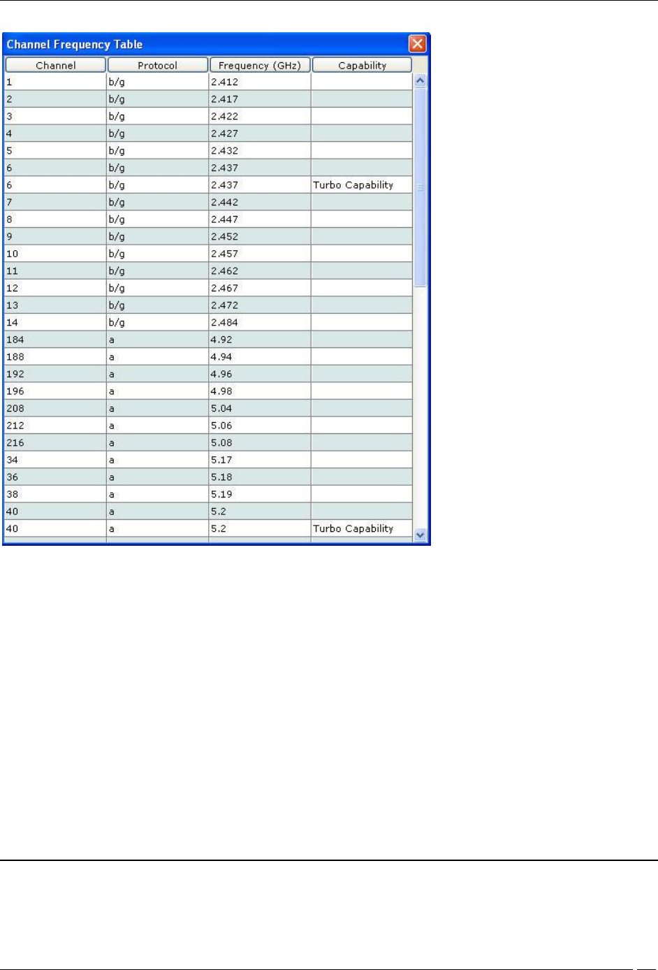
Click the link Channel Frequency Table to view a list of channels, protocols, frequencies, and capabilities.
Administration Tab
SpectraGuard® Enterprise User Guide
306
Channel Frequency Table
Channels to Monitor: Specifies the 802.11a and b/g channels to be used by sensors to monitor WLAN traffic.
Select the check box Select All Standard Channels to select a superset of all the channels. For 802.11a, the
standard sets of channels are 184 – 216 and 34 - 165. By default, this check box is selected.
Select the check box Select All Allowed Channels to select all the allowed channels in the selected operating
region. By default, this checkbox is selected.
Select the check box Additionally, select intermediate channels (works only with 802.11 a/b/g sensor platforms)
to select the channels between the allowed channels that are non-allowed in the selected operating region. Selecting
the option helps the system detect devices operating on illegal channels. By default, this checkbox is deselected.
Turbo Mode: Certain Atheros Chipset based devices use wider frequency bands on certain channels in 802.11 b/g
and 802.11a band of channels. The system is capable of monitoring channels that support Turbo Mode of operation
and detecting any unauthorized communication on these channels. You can select specific or all channels to monitor
wireless activity on Turbo channels. There are ten Turbo channels in a-mode. These channels are 40, 42, 48, 50, 56, 58,
152, 153, 160, and 161. There is only one Turbo channel in b/g-mode that is,6.
Channels to Defend: Specifies the channels to be used by sensors to defend WLAN traffic to protect your
network against various WLAN threats.
Note: It is mandatory that channels selected for defending be selected for scanning. If a channel is selected for
defending and is not already selected for scanning, the system automatically selects that channel for scanning as
Administration Tab
SpectraGuard® Enterprise User Guide
307
well. If you deselect a channel from Channels to Monitor, then this channel is also deselected from Channels to
Defend section.
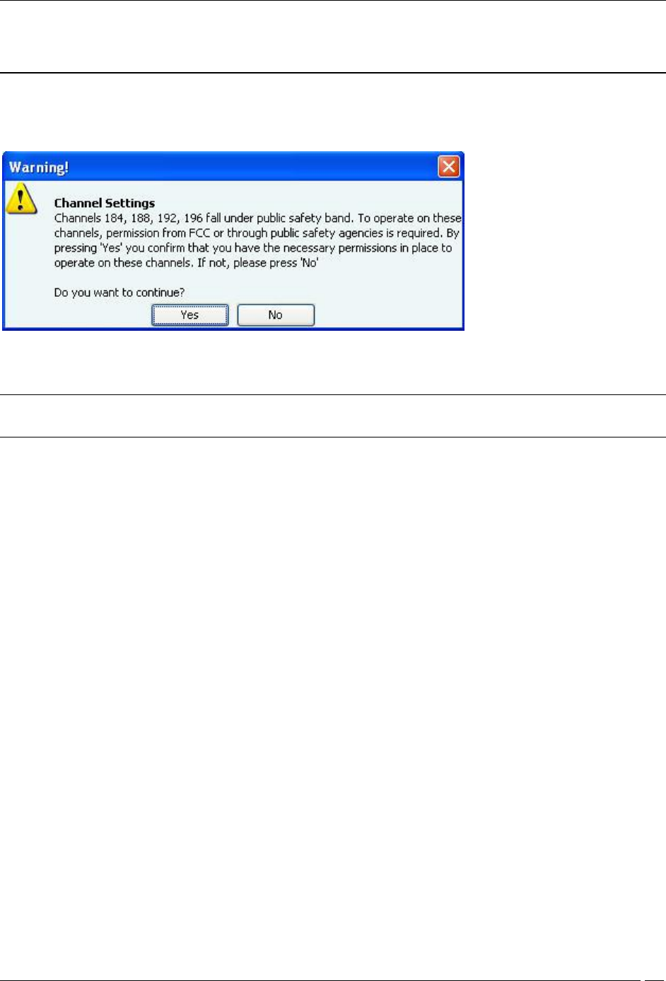
For operating region US, if you select channel 184, 188, 192, or 196 under Channels to Monitor or Channels to
Defend, and click Save, the following message box appears.
Warning while turning on channel in US safety band
If you click Yes, the channel is selected. If you click No, the channel is not selected.
Note: Channels 184,188, 192, 196 fall under the public safety band in the US. They are turned off, by default,
under Channels to Monitor and Channels to Defend.
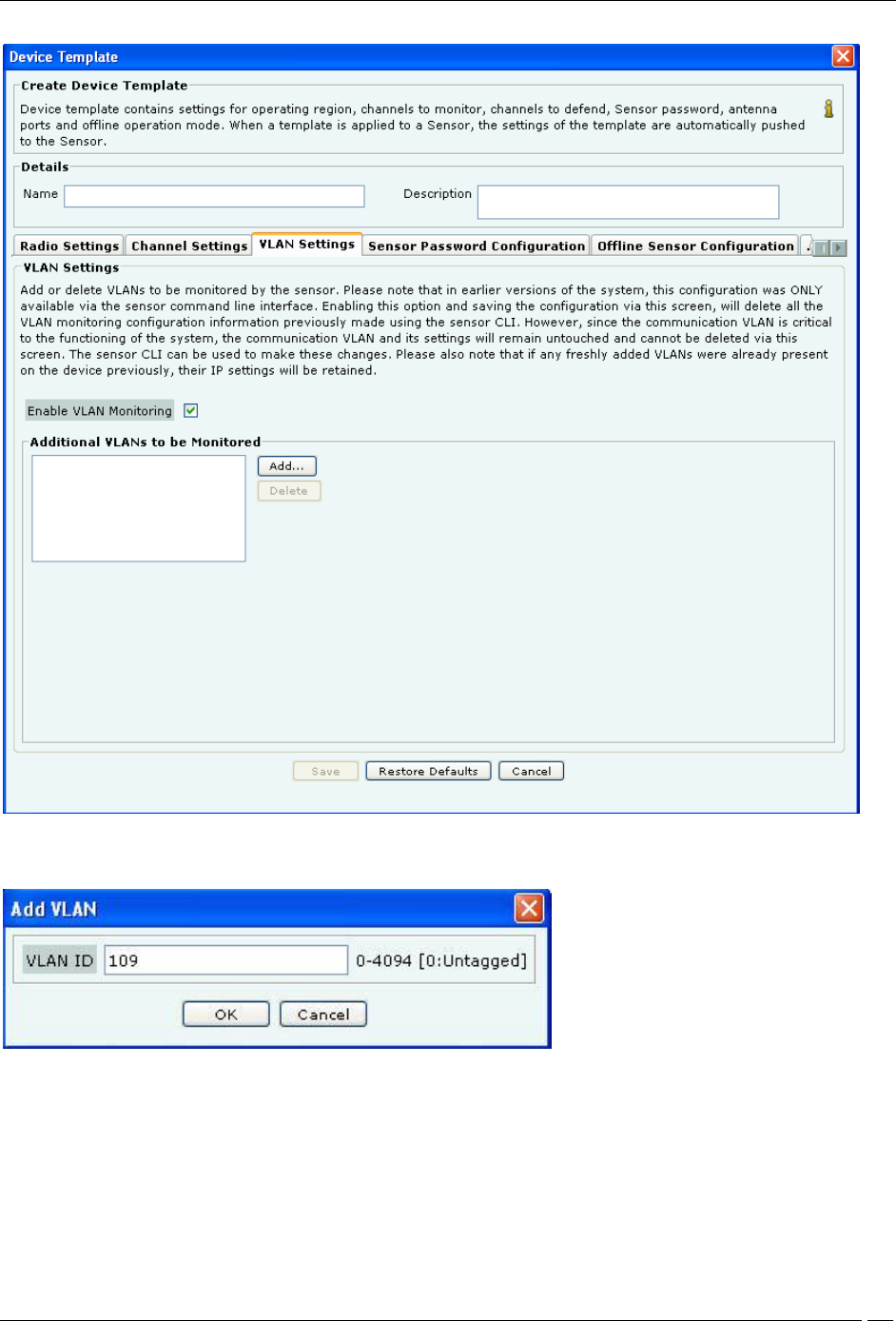
VLAN Settings
The VLAN Settings tab facilitates the management of VLANs to be monitored by a sensor device in sensor mode.
These settings are applicable to sensor devices in sensor mode of operation only; and not to sensor devices in ND or
AP mode of operation. In the earlier versions of the system, specifying the VLAN to be monitored, or deleting the
VLANs that were being monitored could be done using the sensor command line interface only. From this version,
the addition and deletion of VLANs to be monitored can be done from the user interface as well, using the VLAN
Settings tab.
Administration Tab
SpectraGuard® Enterprise User Guide
308
VLAN Settings
To add VLANs to be monitored, select the Enable VLAN Monitoring check box. Click Add to add a VLAN.
Add VLAN
Enter the VLAN ID and click OK, to add the VLAN to the list of monitored VLANs.
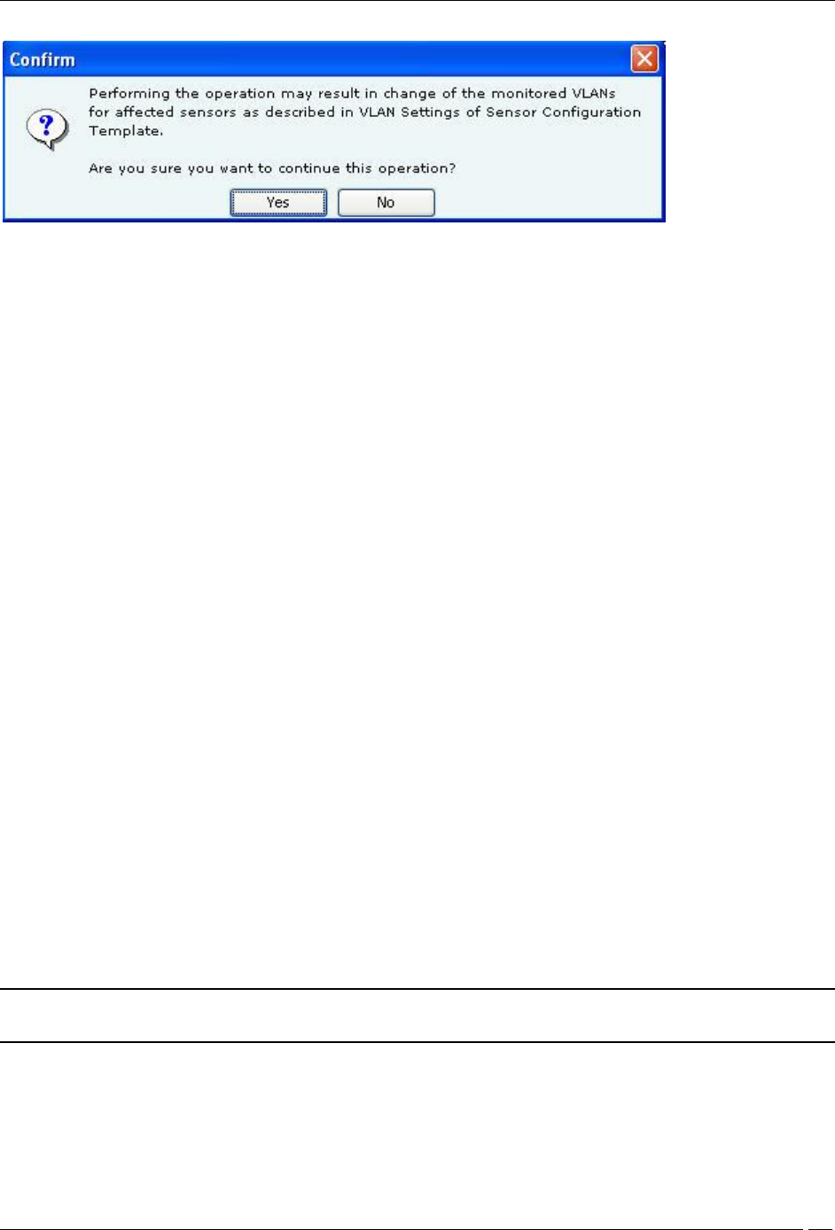
When you save changes to the VLAN Settings tab by clicking Save, an additional confirmation message appears,
after clicking OK on the Confirmation-Save message.
Administration Tab
SpectraGuard® Enterprise User Guide
309
Confirmation-Save VLAN Settings
The VLAN Settings are saved only when Yes is clicked on this message.
If you click No, the Confirmation-Save message will re-appear.
The VLANs created should not exceed the “MAX allowed VLAN to monitor” for the sensor mode. If the number of
VLANs specified by user exceeds this maximum count, the maximum VLANs (created &) monitored should be the
first maximum VLAN entered by user in sensor template.
To delete a VLAN, select the VLAN from the Additional VLANs to be Monitored area, and click Delete.
The changes in the sensor template will affect the working of the sensor operating in sensor mode in the following
way-
If the sensor template for a sensor has “Enable VLAN Monitoring” checkbox not selected, then all the existing
VLANs remain as is, there would be no change to existing VLANs.
If the sensor template for this sensor has “Enable VLAN Monitoring” checkbox selected, then
(a) All the VLANs which were previously configured on sensor which are also in sensor template’s VLAN list of
'VLANs to be monitored' would not have any effect on their configuration.
(b) If communication VLAN currently configured on the sensor is not in sensor template’s VLAN list of 'VLAN to be
monitored', then the communication VLAN’s configuration wouldn’t change.
(c) All the VLANs which were previously configured on sensor but are not present in sensor template’s VLAN list of
'VLANs to be monitored' would have their VLAN configuration deleted from that sensor (Except if the VLAN is
communication VLAN as clause 'b' states).
(d) All the VLANs which were previously NOT configured on sensor but are present in sensor template’s VLAN list
of 'VLANs to be monitored' would be created on the sensor and by default DHCP settings would apply for these
VLANs being created.
when the sensor is in offline mode, the communication VLAN is monitored.
Sensor Password Configuration
Sensor Password setting allows you to manage the password for user config on the sensor Command Line Interface
(CLI). By defining a password in the sensor template, you can manage the password for a group of sensors without
having to change it on each sensor separately. Type a new password or click Restore Default to change the current
password settings. If you choose Restore Default, then the password setting will be the same as that in the System
Template.
Note: If a sensor template contains a blank password, then the sensors, to which this template is assigned, retain
their existing password. Factory setting of the System Template contains a blank password.
Administration Tab
SpectraGuard® Enterprise User Guide
310
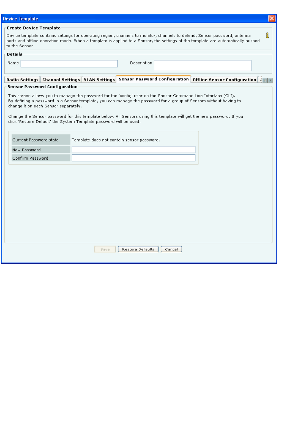
Sensor Password Configuration
Under Sensor Password Configuration tab specify the following:
Current Password state: Specifies that the new password must be the same as the one specified in the System
Template.
New Password: Enter the new password to be assigned as user ‘config’ password for all sensors associated with
the sensor template being edited.
Confirm Password: Reenter the password to help confirm the new password before saving.
Offline Sensor Configuration
This feature provides some security coverage even when there is no connectivity between a sensor and the server.
The sensor provides some classification and prevention capabilities when it is disconnected from the server. The
sensor also raises events, stores them, and pushes them back to the server on reconnection.
Administration Tab
SpectraGuard® Enterprise User Guide
311
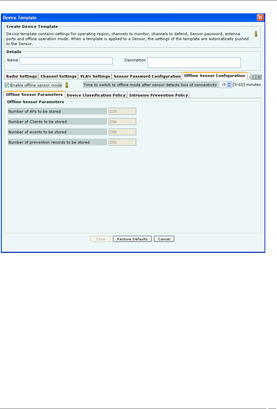
Offline Sensor Configuration-Offline Sensor Parameters
Enable offline Sensor mode: Select this checkbox to enable the offline sensor mode. When the offline sensor mode
is enabled, the sensor continues to detect and classify devices, raise event alerts, and prevent ongoing threats. (Default:
Selected)
Time to switch to offline mode after Sensor detects loss of connectivity: Specify the time after which, if the
sensor does not receive any communication from the Server and Enable offline Sensor mode is enabled, the sensor
switches to the offline mode.
(Minimum: 5 minutes; Maximum: 60 minutes; Default: 15 minutes)
Under Offline Sensor Parameters tab, you can view the following:
Number of APs to be stored: Number of APs that the sensor will continue to detect in Offline mode (Default:
128)
Number of Clients to be stored: Number of Clients that the sensor will continue to detect in Offline mode
(Default: 256)
Number of events to be stored: Number of events that the sensor will continue to raise in Offline mode (Default:
256)
Number of prevention records to be stored: Number of prevention records that the sensor will continue to store
in Offline mode to prevent ongoing threats (Default: 256)
Administration Tab
SpectraGuard® Enterprise User Guide
312
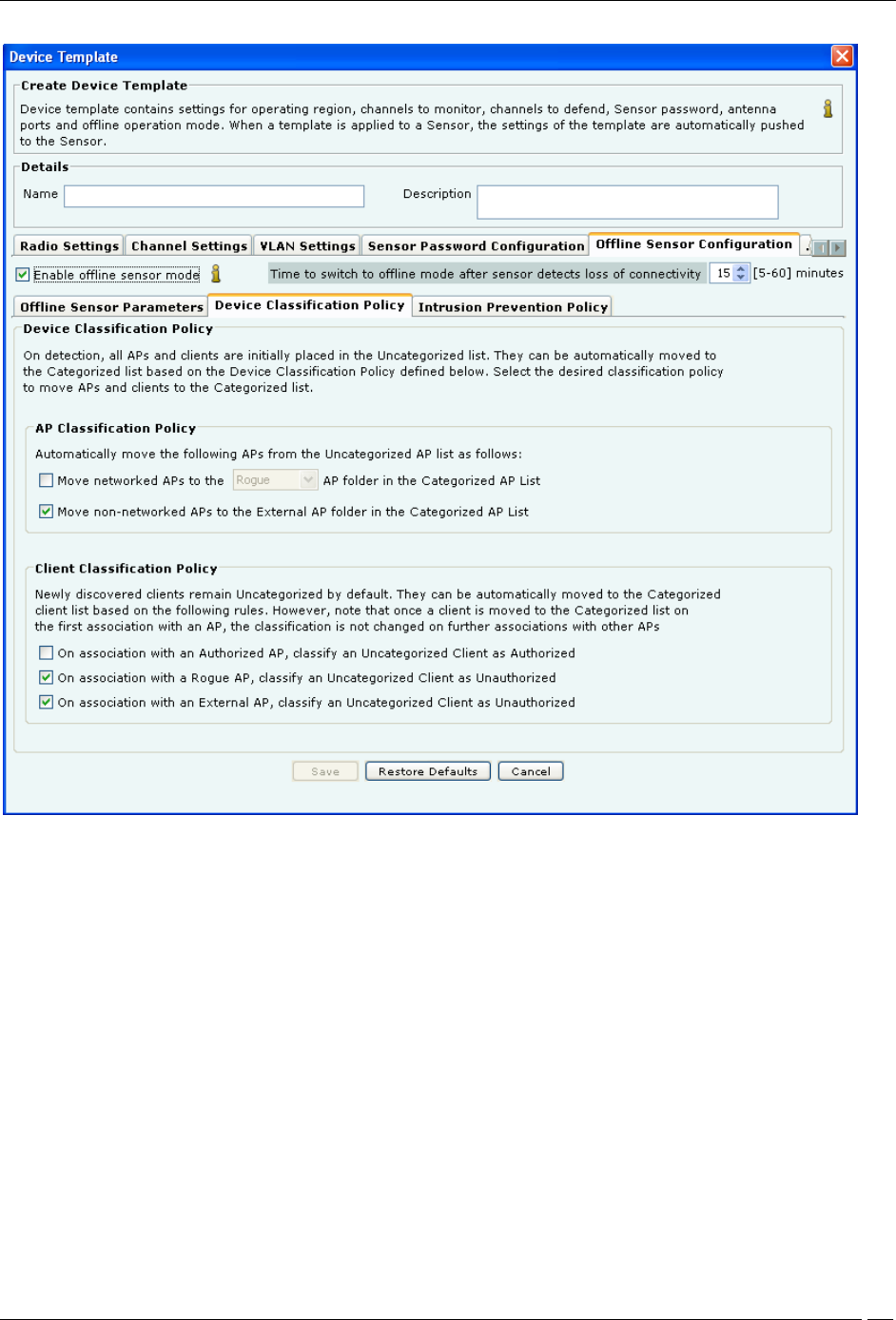
Offline Sensor Configuration-Device Classification Policy
Under Device Classification Policy tab specify the desired classification policies to move APs and Clients from the
Uncategorized list to the Categorized list:
Under AP Classification Policy, select one or more options to enable the system automatically move APs from
the Uncategorized AP list to the Categorized AP list:
Move networked APs to the Rogue or Authorized AP folder in the Categorized AP List
Move non-networked APs to the External AP folder in the Categorized AP List
Under Client Classification Policy, select one or more options to enable the system automatically classify Clients
based on their associations with APs:
On association with an Authorized AP, classify an Uncategorized Client as Authorized
On association with a Rogue AP, classify an Uncategorized Client as Unauthorized
On association with an External AP, classify an Uncategorized Client as Unauthorized
Administration Tab
SpectraGuard® Enterprise User Guide
313
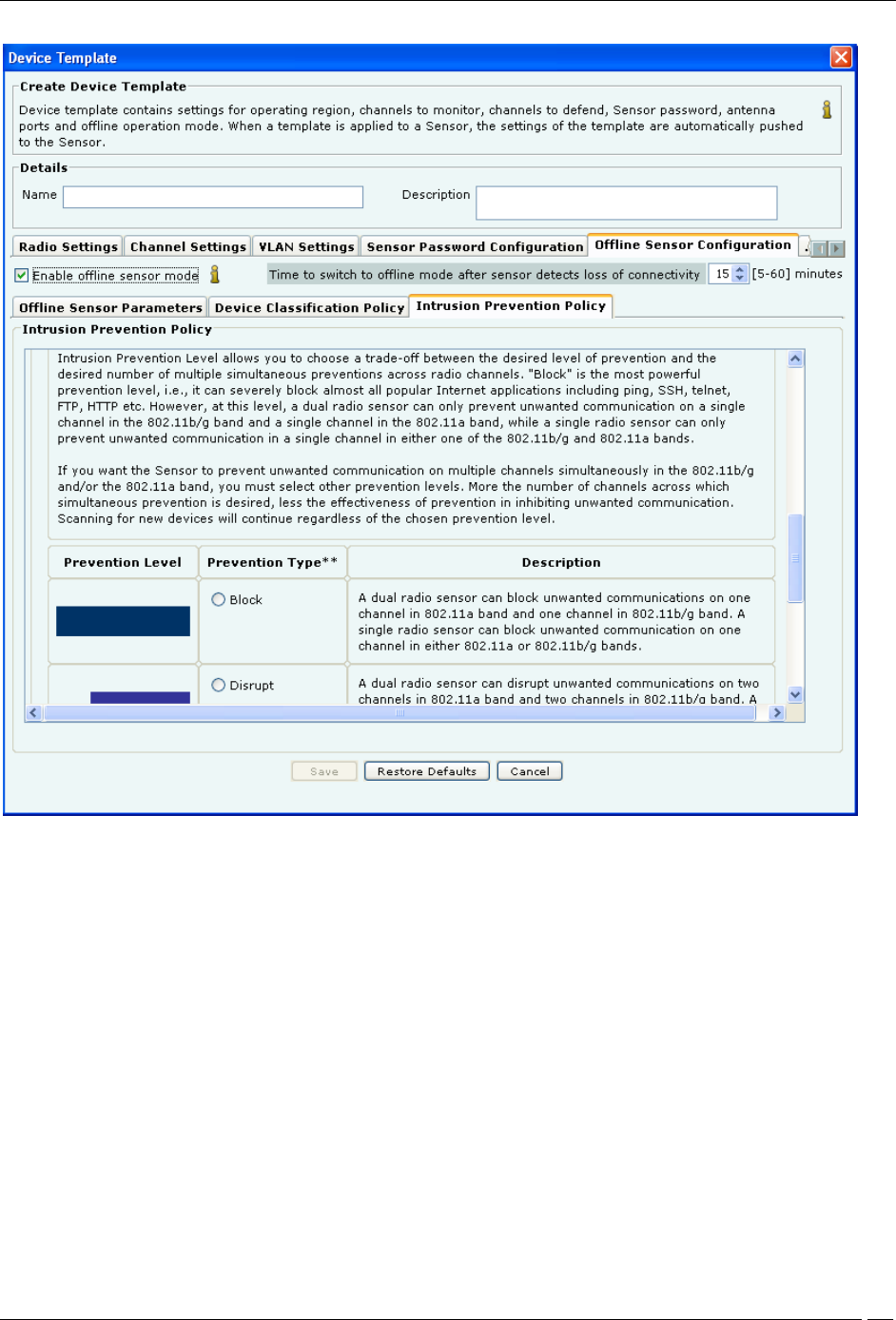
Offline Sensor Configuration-Intrusion Prevention Policy
Under Intrusion Prevention Policy tab enable intrusion prevention against the following threats:
Rogue APs
APs categorized as Rogue
Uncategorized APs that are connected to the network
Misconfigured APs
APs categorized as Authorized but using no security mechanism (Open)
APs categorized as Authorized but using weak security mechanism (WEP)
Client Mis-associations
Authorized Client connections to APs categorized as External
Unauthorized Associations
Unauthorized Client connections to APs categorized as Authorized
Adhoc Connections
Authorized Clients participating in any adhoc network
Honeypot/Evil Twin APs
Authorized Client connection to Honeypot/Evil Twin APs

Administration Tab
SpectraGuard® Enterprise User Guide
314
Additionally, specify the intrusion prevention level that allows you to choose a trade-off between the desired level of
prevention and the desired number of multiple simultaneous preventions across radio channels. You can choose
either of the following prevention levels:
Block
Disrupt
Interrupt
Degrade
Antenna Selection and Port Assignment
Antenna connectivity setting is an advanced setting and should be used with utmost care. This setting allows you to
provide additional information about the type of antennas connected to the sensor. You need to change this setting
only if you use sensors that allow you to connect antennas.
Note: Antenna Selection feature is available for SS-300 Sensor and Port Assignment feature is available for SS-
200 Sensor.
Applying a template with a particular antenna setting to a sensor with incompatible antenna connection can result in
a loss of system functionality leading to higher security risks. The default setting being “Diversity On”. It is
recommended that you avoid changing the Antenna Port Setting in the default sensor template. If you use sensors
with 2 single band antennas, create a separate template with “Diversity Off” setting and manually apply it to a group
of sensors which use single band antennas.
Note: The default setting is “Diversity On” which means both the antennas are dual band.
Administration Tab
SpectraGuard® Enterprise User Guide
315
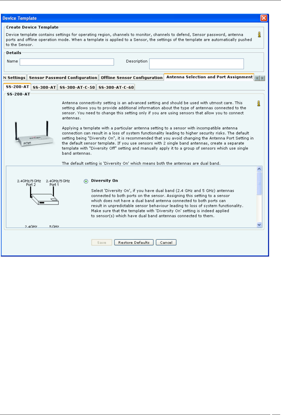
Antenna Selection and Port Assignment
Under Antenna Selection and Port Assignment tab
1 For Port Assignment for SS-200 Sensor
Select Diversity On or Diversity Off
Diversity On: This is the default setting, which means both the antennas are dual band. Select this option if you
have a dual band (2.4 GHz and 5 GHz) antenna connected to both the ports on the sensor. Assigning this setting to a
sensor which does not have a dual band antenna connected to both ports, can result in unpredictable sensor behavior
leading to loss of system functionality. Make sure that the template with “Diversity On” setting is indeed applied to
sensor(s), which have dual band antenna connected to them.
Diversity Off: Select this option if and only if your sensors have a 5 GHz antenna connected to Port 1 and a 2.4
GHz antenna connected to Port 2. The figure in the Antenna Port Assignment tab shows how to locate the ports to
ensure that the single band antennas are correctly connected. Assigning this setting to a sensor that does not have
single band antennas connected as mentioned above can result in unpredictable sensor behavior leading to loss of
system functionality. Make sure that the template with Diversity Off setting is indeed applied to sensor(s) that have
two different single band antennas supporting 2.4 GHz and 5 GHz frequency bands and connected as mentioned
above.
Administration Tab
SpectraGuard® Enterprise User Guide
316
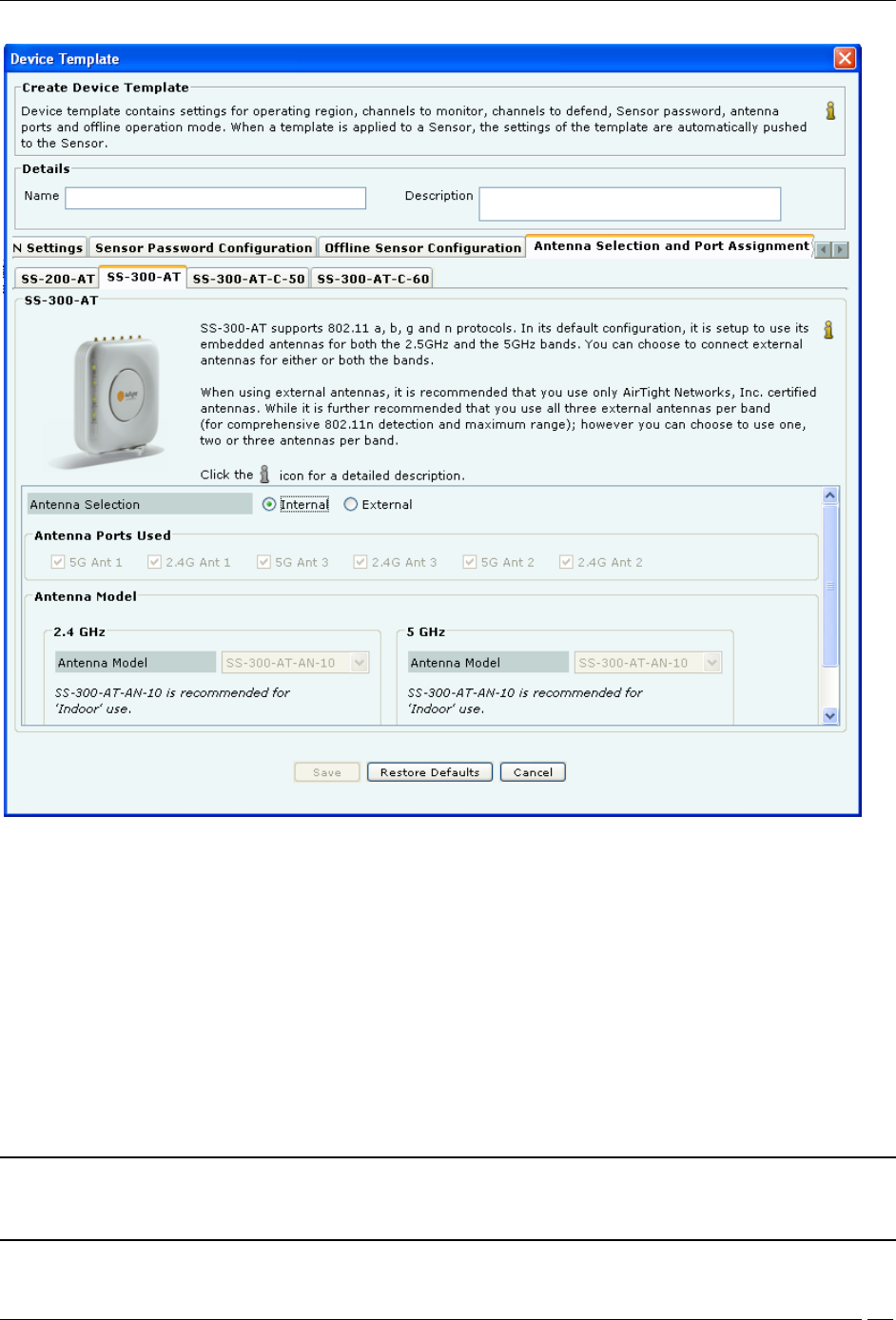
Antenna Selection and Port Assignment-SS-300-AT
2 For Antenna Selection for SS-300-AT Sensor
Select Internal or External in Antenna Selection.
The default configuration for SS-300-AT sensors is to use internal antennas. If you want to connect external antennas
to SS-300-AT sensors, select External radio button. This enables:
Antenna Ports Used: Six external antenna ports are available in every SS-300-AT type sensors. Out of these six
ports, three ports are for 5 GHz and three for 2.4 GHz. Depending upon number of external antennas connected; click
the checkboxes corresponding to the antenna ports in the sensor template. Indentation marks are provided on the
sensor enclosure describing the radio and antenna port, like 5G Ant1, 2.4G Ant2, and so on.
Antenna Model: Select the appropriate antenna model for 2.4 GHz and 5GHz antennas from the drop down list.
The antenna models available are SS-300-AT-AN-10 is recommended for Indoor use, SS-300-AT-AN-20 is
recommended for Outdoor use, SS-300-AT-AN-40 is recommended for Outdoor use. Select Other and enter the
antenna model of your choice in the Enter Antenna Model field.
Recommendation: It is recommended that you should use AirTight™ certified antennas for better coverage and
performance. If you are using Other Antenna Model, please make sure that they comply with the SS-300-AT
sensor’s electrical characteristics.
Administration Tab
SpectraGuard® Enterprise User Guide
317
Points to note for SS-300 Sensor – Antenna Selection
1 Antenna selection feature is not available in SS-300-AT-C-01 model type. For this model, internal antennas will
be selected irrespective of the “Antenna Selection” settings.
2 There is no need to perform any special configuration for connecting external antenna for SS-200-AT type of
sensors. You can simply connect external antenna for SS-200-AT sensors.
3 In case of external antenna use with SS-300-AT-C-05 and SS-300-AT-C-10 sensor models, three antenna pairs are
recommended. If you choose to use only two antenna pairs, the two antennas pairs must be connected to ports
marked as Ant1 and Ant2 (ports at the two ends of the edge with the connectors) for proper operation.
4 In case of external antenna use, it is required that a minimum of two antenna pars are connected to the SS-300-
AT-C-05 and SS-300-AT-C-10 sensors. If you connect only one antenna pair to these models, some threats that operate
in high bit rates available with the 802.11n protocol will not be visible to the system and consequently, the system
will be unable to report and protect the network against such threats.
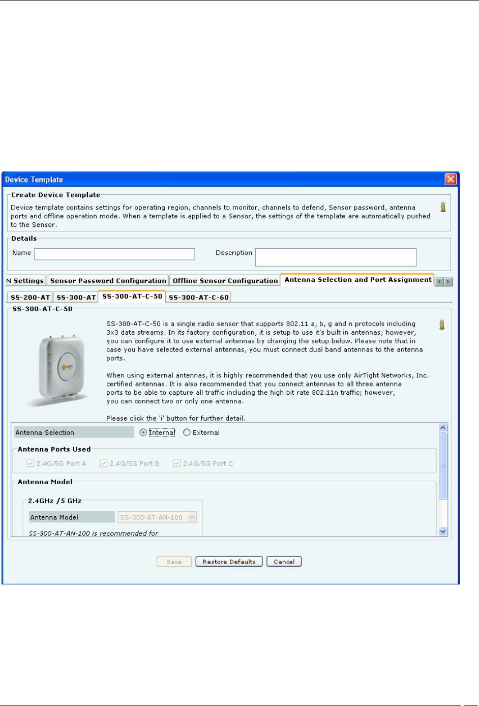
Antenna Selection and Port Assignment-SS-300-AT-C-50
i. For Antenna Selection for SS-300-AT-C-50
Select Internal or External in Antenna Selection.
The default configuration for SS-300-AT-C-50 sensors is to use internal antennas. If you want to connect external
antennas to SS-300-AT-C-50 sensors, select External radio button. This enables:
Administration Tab
SpectraGuard® Enterprise User Guide
318
Antenna Ports Used: Three external antenna ports are available in every SS-300-AT-C-50 type sensors.
Depending upon number of external antennas connected; click the checkboxes corresponding to the antenna ports in
the sensor template. Indentation marks are provided on the sensor enclosure describing the radio and antenna port,
like 2.4G/5G Ant 1, 2.4G/5G Ant 2, and 2.4G/5G Ant 3.
Note: To derive the full benefit of 802.11n range and to be able to capture all 802.11n traffic all three antennas must
be connected.
Antenna Model: Select the appropriate antenna model for 2.4GHz/5GHz antennas from the drop down list. The
antenna models available are SS-300-AT-AND-12-3 and SS-300-AT-AND-14-3 recommended for Indoor use and
select Other and enter the antenna model of your choice in the Enter Antenna Model field.
Note: It is recommended that if you select external antennas, you must connect dual band antennas to the antenna
ports.
Click Save to save all settings.
Click the icon to edit an existing sensor template. When an existing sensor template is edited a Confirmation –
Save dialog appears indicating the modifications, by selecting the tabs that were modified. You are allowed to
uncheck a tab if you wish to cancel those modifications. Click OK to save the changes for the selected tab.
Note: Name and Description of the sensor template are automatically saved.
Click Save As to save the sensor template with a different name without modifying the original template.
Click Restore Default to revert to the System Template. The system enables you to select tabs to control the settings
that will be restored to the default values. If you click Restore Default on the System Template, parameters under the
selected tabs are restored to their factory default settings. A Confirmation – Restore Default dialog appears with a
list of tabs selected, for which default settings will be applied.
Important: The system has the ability to scan and defend on 4.920-4.980 GHz and 5.470-5.725 GHz channels in
US/Canada and IEEE 802.11j channels 4.920-4.980 GHz and 5.040-5.080GHz channels in Japan.
Click the icon to view an existing sensor template. Click the icon to delete an existing sensor template.
Administration Tab
SpectraGuard® Enterprise User Guide
319
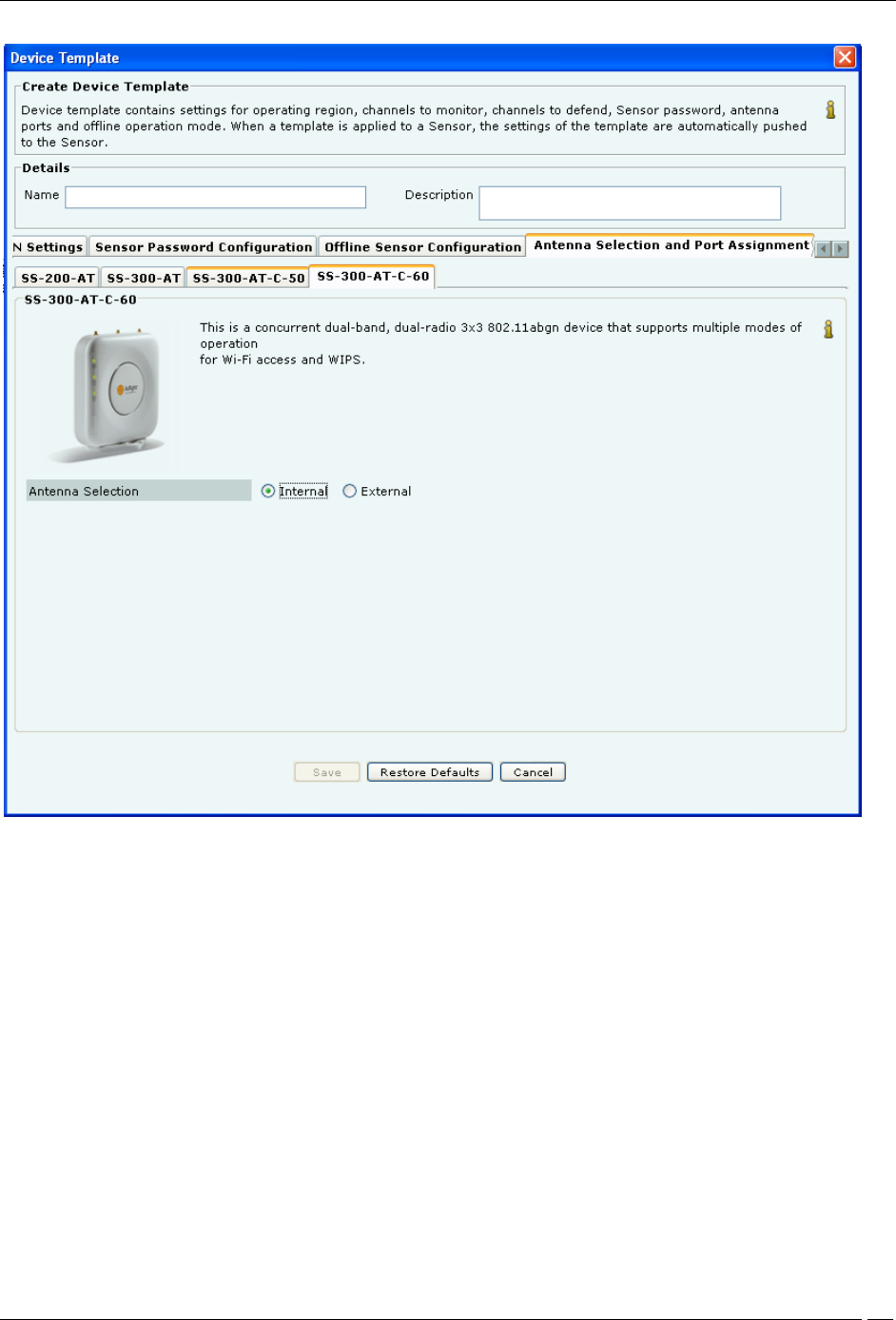
Antenna Selection and Port Assignment-SS-300-AT-C-60
ii. For Antenna Selection for SS-300-AT-C-60
Select Internal or External in Antenna Selection.
The default configuration for SS-300-AT-C-60 is to use internal antennas.
Sensor Access Log
The System provides you with a provision to send the sensor access logs to the Syslog server. Following logs could
be sent
to a Syslog server of user's choice:
1. Login attempts to the sensor from the console or secure shell (ssh) along with the result, i.e. Success or
Failures
2. Configuration changes done on the sensor through the command line interface (CLI)
3. Attempts and outcome of set, reboot, reset factory commands executed on the sensor.
This facility could be enabled or disabled on a per Sensor Configuration Template basis.
This facility is useful for audit purposes. This facility could be turned on or off from Sensor Configuration Template
for
Administration Tab
SpectraGuard® Enterprise User Guide
320
that particular sensor. The configuration of Syslog server IP to which the sensor access logs are to be sent, is done
through
the Sensor Access Log tab.
The following screen shows the Sensor Access Log tab.
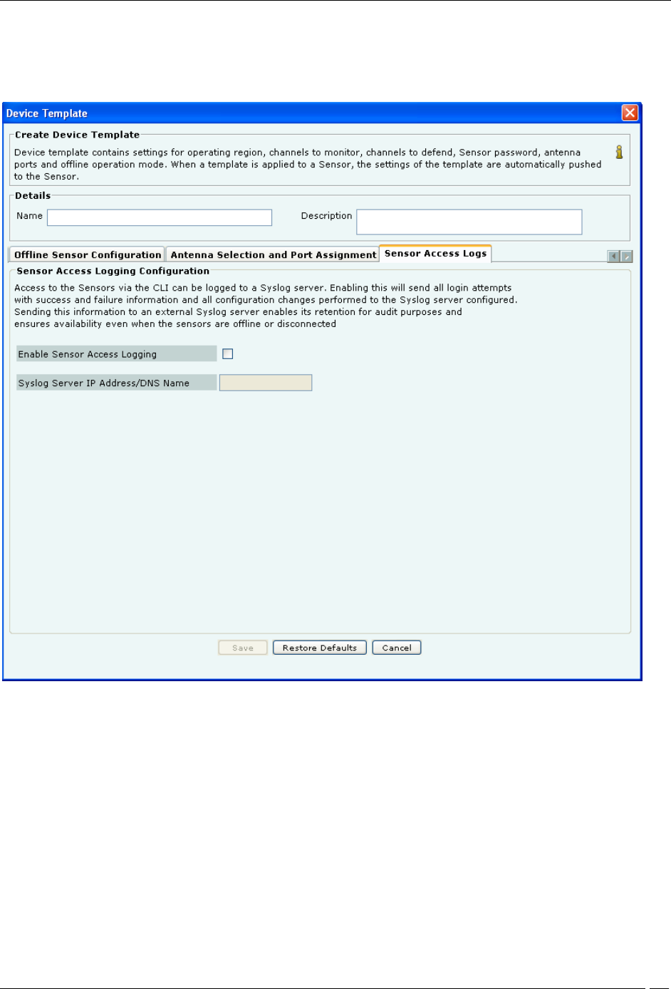
Sensor Access Logs
The following fields are present in the Sensor Access Logs tab:
Enable Sensor Access Logging: Select the Enable Sensor Access Logging check box, to enable sending of sensor
access logs to a Syslog server. This checkbox is deselected, by default.
Syslog Server IP address/DNS name: Specify the IP address or DNS name of the Syslog server to which the sensor
access logs are to be sent in this field. IPv4 addresses are allowed in this field. This field is blank and disabled, by
default. It is enabled when you select the Enable Sensor Access Logging check box.
Click Save, to save the Sensor Access log settings.
Click Cancel, to cancel any changes made to this tab.
Click Restore Defaults, to restore default values of the fields in the Sensor Access Log tab.
Once sensor access logging is enabled, the sensor reboots and starts sending information to the Syslog server at the IP
address specified through this tab.
Administration Tab
SpectraGuard® Enterprise User Guide
321
Note: Check the firewall settings of the Syslog server and modify them, if needed, so that the System is able to send
the logs to the Syslog server.
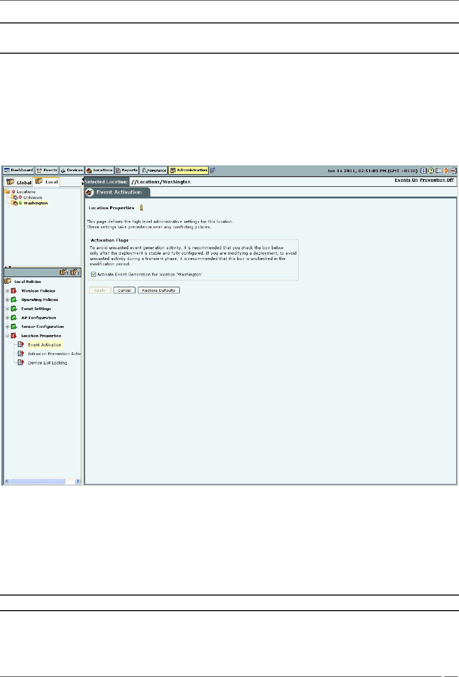
Location Properties
The Location Properties option enables you to define high-level administrative settings for a selected location. These
settings take precedence over any conflicting policies.
Event Activation
AirTight recommends that you select the check box Activate Event Generation for location ‘<selected location>’ only
after the deployment is stable and fully configured. If you are modifying a deployment, deselect the check box to
avoid spurious activity during the transient phase.
Event Activation
Intrusion Prevention Activation
AirTight recommends that you select the check box Activate Intrusion Prevention for location ‘<selected location>’
only after the deployment is stable and fully configured. If you are modifying a deployment, deselect the checkbox to
avoid spurious activity during the transient phase.
Note: Intrusion Prevention Activation section is not visible if WIDS license is applied.
Authorized APs should be in the Authorized folder before activating intrusion prevention. Their network
connectivity icon may show the status as Wired, Unwired, or Indeterminate.
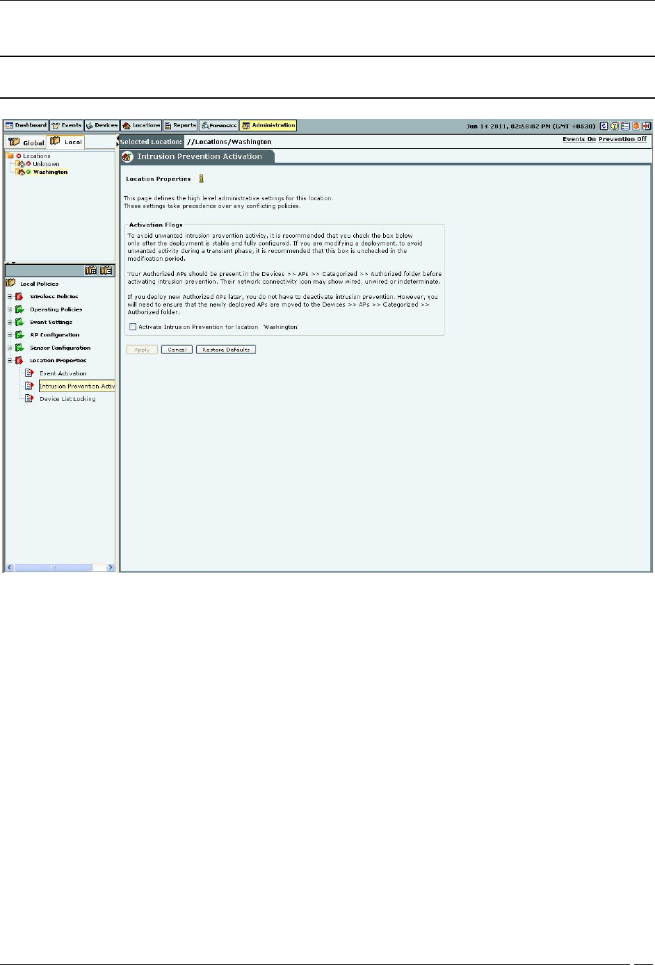
Administration Tab
SpectraGuard® Enterprise User Guide
322
Note: If you deploy new Authorized APs later, you do not have to deactivate intrusion prevention.
However, you need to ensure that the newly deployed APs are moved to the Authorized folder.
Intrusion Prevention Activation
Device List Locking
You can lock the list of Authorized APs and Clients for a selected location by checking the two check boxes Lock AP
List for location ‘<selected location’> and Lock Client List for location ‘<selected location’>. If you lock a particular
device list, no more devices of that type can be subsequently automatically Authorized for that location. As APs are
not automatically moved to Authorized folder, locking the Authorized AP list means that no wired APs will be
tagged as Potentially Authorized at this location; they will become Potentially Rogue and may be automatically
moved to the Rogue folder based on the AP Auto-Classification policy. You should use this feature only after you
have identified and categorized all authorized devices. Any new devices added after the list is locked has to be
manually moved to the Authorized category.
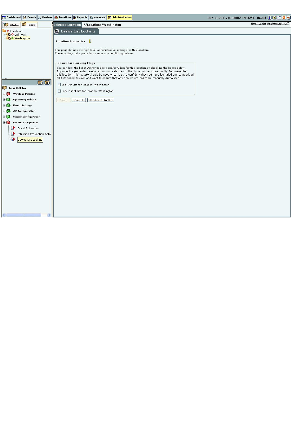
Administration Tab
SpectraGuard® Enterprise User Guide
323
Device List Locking

Appendix A1:SNMP Interface
SpectraGuard® Enterprise User Guide
324
Appendix A1:SNMP Interface
The system sends traps to an SNMP management station when a Sensor generates an event. You can view a trap sent
from the system using SNMP manager software such as HP Open View or MG Soft MIB (Management Information
Base) browser. The SNMP manager software allows you to view a detailed description of the trap and thereby the
functioning of your wireless network. Perform the following steps from the SNMP management station to receive
traps from the system and to dig deeper into the Sensors.
1. Configure the system to specify the IP address, community string, and the SNMP version of the SNMP
management station. This can be done from the Administration->Local tab->ESM Integration->SNMP screen
of the Console.
2. Compile the MIB file and enable the SNMP management station to receive traps. The system currently
generates traps for all the events. The format of the trap is: SpectraGuard Event.
The Internet Assigned Numbers Authority (IANA) assigned Private Enterprise Number for AirTight® Networks, Inc.
is 16901.
SNMP trap contains following variable bindings:
1. eventShortText is the short text identifying the type of an event. For example, “Rogue AP active”
2. deviceMAC*, deviceType* - Information of the device(s) participating in the corresponding SpectraGuard
event
deviceMAC* object is the MAC address of participating device(s). For example, 00:11:95:1E:A7:56
deviceType* object is the type of participating device. For example, Access Point, Client, Sensor. If a
SpectraGuard event contains more than three participating devices, then deviceType and
deviceMAC of only first three devices is sent out in the SpectraGuardEvent notification.
3. eventID is the unique sequence number which identifies specific instance of an event. This sequence number
is always auto-incremented by one for every newly event raised.
4. eventMajorType represents the top level category of an event. For example, security, system, performance
5. eventIntermediateType is the sub-category within eventMajorType
6. eventMinorType is the actual identifier of the event type
7. eventSeverityLevel is the configured Severity level of the SpectraGuard event. For example: high, medium,
and low.

Appendix A2:Syslog Interface
SpectraGuard® Enterprise User Guide
325
Appendix A2:Syslog Interface
SGE also sends events as Syslog messages. Any standard Syslog receiver (e.g. Syslog watcher from snmpsoft) can be
used to monitor the Syslog messages sent by SGE.
SGE can send Syslog messages either 'Plain Text' or 'IDMEF' format based on the 'Message Format' selected while
configuring Syslog receivers on Syslog configuration screen.
The format of 'Plain Text' Syslog message is shown below.
<<HW Address of Primary Interface of SGE>><Product Name> v<SGEVersion>: <Event Summary Description>: <IP
Address>//<Location> : <Event Date-Time>: <Event Severity Level>:<Event ID>:<Event Major Type>:<Event
Intermediate Type>:<Event Minor Type>
Product Name: SpectraGuard Enterprise
SGE Version: SpectraGuard Enterprise Release
Event Summary Description: Summary description for the event
IP Address: IP Address of the SpectraGuard Enterprise Server
Location: Location in SGE console at which this event is generated.
Event Date-Time: Date-Time at which event was generated in SGE
Event Severity Level: Configured severity level of the SpectraGuard Enterprise Event e.g High, Medium or
Low
Event ID: Unique sequence number which identifies specific instance of an event. This sequence number is
always auto-incremented by 1 for every new event raised.
Event Major Type: It represents the top level category of an event.
Event Intermediate Type: It represents the sub-category within Event Major Type
Event Minor Type: It is the actual identifier of the event type
Example:
"<xx:yy:zz:aa:bb:cc>SpectraGuard Enterprise v6.5 : Start: Rogue AP [Symbol_CC:31:B0] is active. :
192.168.8.134://Locations/Unknown : 2010-06-10T05:16:28+00:00 : High : 21218 : 5 : 59 : 779"
The IDMEF message contains some additional information which is not available with 'Plain Text' format
Product Vendor: AirTight
SGE Operating System: Linux
SGE Operating System Version: Operating system version of SGE appliance
Event Short Name: Short text identifying the type of an event
The format of 'IDMEF' Syslog message is shown below.
"<HW Address of Primary Interface of SGE><?xml version=""1.0""?>
<!DOCTYPE IDMEF-Message PUBLIC ""-//IETF//DTD RFC XXXX IDMEF v1.0//EN"" ""/var/tmp/libidmef-1.0.2-
beta1-buildroot/usr/share/idmef-message.dtd"">
<IDMEF-Message version=""1.0"">
<Alert messageid="<EventID>">
<Analyzer analyzerid="<IP Address>" name="<Product Name>" manufacturer="<Product Vendor>"
model="""" version="<SGE Version>" class="""" ostype="<SGE Operating System>" osversion="<SGE Operating
System Version>">
<Node>
<location><IP Address>//<Location></location>
</Node>
</Analyzer>
<CreateTime ntpstamp="<Event Date-Time in NTP format>">Event Date Time</CreateTime>
<Classification ident="<Event Major Type><.Event Intermediate Type>.<Event Minor Type>" text="<Event
Short Description>"/>
<Assessment>
<Impact severity="<Event Severity>"></Impact>
</Assessment>

Appendix A2:Syslog Interface
SpectraGuard® Enterprise User Guide
326
<AdditionalData type=""string"" meaning=""EventShortName""> <Event Short Name> </AdditionalData>
</Alert></IDMEF-Message>"
All Syslog messages are sent with Syslog facility as 'System' and Syslog severity as 'Critical', 'Info' or 'Warning' based
of SpectraGuard Enterprise event severity.
SGE Severity Syslog Severity
High Critical
Medium Warning
Low Info
Appendix B:Glossary of Terms and Icons
SpectraGuard® Enterprise User Guide
327
Glossary of Terms and Icons
This section provides a quick reference to wireless networking terms and acronyms used in the guide.
Acronyms
Abbreviation
Description
AP
Access Point
DNS
Domain Name System (or Service or Server)
DoS
Denial of Service
ESM
Enterprise Security Management
IEEE
Institute of Electrical and Electronics Engineers
LAN
Local Area Network
LDAP
Light-Weight Directory Access Protocol
LWAPP
Light-Weight Access Point Protocol
MAC
Media Access Control
MIB
Management Information Base
NAV
Network Allocation Vector
NOC
Network Operations Center
OPSEC
Operations Security
RF
Radio Frequency
SMTP
Simple Mail Transfer Protocol
SNMP
Simple Network Management Protocol
SSID
Service Set Identifier
Appendix B:Glossary of Terms and Icons
SpectraGuard® Enterprise User Guide
328
SSL
Secure Socket Layer
UDP
User Datagram Protocol
VPN
Virtual Private Network
WEP
Wired Equivalent Privacy
WLAN
Wireless Local Area Network
WLSE
Wireless LAN Solution Engine
Glossary of Terms
Term
Description
.SPM file
Planner File, a proprietary AirTight® Networks file format that holds information
about RF signal values, placement of devices, and device settings
802.11
An IEEE wireless LAN specification for over-the-air interface between a wireless
Client and a base station or between two wireless Clients
Access Point
Access Point also referred to, as an AP is a station* that provides distribution
services. It is the hub used by wireless Clients for communicating with each other
and connecting to the WLAN
* A station is the component that connects to the wireless medium
Ad hoc Network
A network formed by peer-to-peer connections between wireless Clients. It is difficult
to enforce tight security policy controls on ad hoc connections. Therefore, ad hoc
connections create a security vulnerability
Authorized client
An Authorized Client is one that has successfully connected to an Authorized AP at
least once. Once identified as Authorized, a Client remains Authorized until it is
deleted by the administrator and is re-classified as Unauthorized
Auto Location Tagging
A feature provided by the system that automatically tags devices and events based
on the Sensors that see the event and the location of the devices that participate in
the event
Categorized Devices –
APs
This section of the Dashboard screen displays a list of all the APs automatically and
manually categorized
Classification Policy
Classification Policy allows you to define AP and Client classification policies to control
automatic movement of APs and Clients to the appropriate folders
Client
A laptop, a handheld device, or any other system that uses the wireless medium
(802.11 standard) for communication
Community String
Community string is a key used to authenticate a message sent by the SNMP agent
to the SNMP manager
DNS
Domain Name Service, an Internet service that translates domain names into IP
addresses
DoS
Denial of Service, an attack that degrades the performance of an official WLAN
Appendix B:Glossary of Terms and Icons
SpectraGuard® Enterprise User Guide
329
Dual Radio AP
An AP with two radios to support Clients on multiple bands
Hostname
A unique name by which a computer is identified on the network
Indeterminate AP
An AP for which the system cannot determine whether it is plugged into your wired
network. This AP should be inspected and manually moved to one of the AP folders
Intrusion Prevention
(Quarantine) Policy
The Intrusion Prevention Policy allows the system proactively block an AP or a Client
to automatically protect the network against various wireless security threats
IP Address
Internet Protocol Address, a 32-bit numeric identifier for a computer or a device on
the network
Location Tracking
A distinguishing feature of the system that allows you to automatically locate a
device placed on a floor map
MAC Address
Media Access Control Address, a unique 6-byte (48 bit) address assigned to the
network adapter by the manufacturer and is often transparent to a user; a
networked device has a MAC address corresponding to each network interface
MAC Spoofed AP
An attacker AP masquerades the Authorized AP by advertising the same MAC address
and other features set as the authorized/other AP in its Beacon/Probe Response
frames. The system generates an alert on detection of AP MAC spoofing
Mis-configured AP
An AP in the Authorized list, that is plugged into your wired network but does not
conform to the Network Policy settings (SSID, Vendor, Encryption, and Protocol) for
its network segment
Network Detector
A device that can co-exist on a Trunking switch; the ND can detect as many LAN
segments as you configure on the switch
Network Interface card
An expansion board or a card that is inserted into a computer so that the computer
can be connected to a network
Network Status
Network status specifies if the network is locked or unlocked. Once a protected
network segment is locked, all new APs connected to it are pre-classified as Rogue and
have to be approved manually. If a protected network segment is unlocked, any new
APs connected to this network will be automatically classified based on the Security,
Protocol, SSID, and Vendor Settings
Potentially Authorized
AP
A new AP plugged into your wired network and conforming to the Network Policy
settings (SSID, Vendor, Encryption, and Protocol) for its network segment; this AP
must be inspected before manually moving it to the Authorized AP folder
Potentially External AP
A new AP not plugged into your wired network. This is an AP usually belonging to a
neighbor. It does not pose a threat to your wired network
Potentially Rogue AP
A new AP plugged into your wired network but not conforming to the Network Policy
settings (SSID, Vendor, Encryption, and Protocol) for its network segment. This AP is never
authorized and can be
automatically moved to the Rogue AP folder based on the
Classification Policy
Security Settings
An IEEE 802.11 defined MAC–level privacy mechanism that protects the contents of
data frames from eavesdropping using encryption
SMTP
Simple Mail Transfer Protocol, A protocol for sending e-mail messages between
Servers. Most e-mail systems that send mail over the Internet use SMTP to send
messages from one Server to another
SNMP
Simple Network Management Protocol, a set of protocols for managing complex
networks
Appendix B:Glossary of Terms and Icons
SpectraGuard® Enterprise User Guide
330
Software AP
Software implementation of AP functionalities that permits a WLAN enabled device to
act as an AP
SSID
A unique token identifying an 802.11 WLAN; all wireless devices on a WLAN must
employ the same SSID to communicate with each other
Unauthorized Client
A Client that is not authorized; an Unauthorized Client has never connected
successfully to an Authorized AP
Uncategorized
Devices – APs
This section of the Dashboard screen displays a list of all the newly discovered APs
VPN
Virtual Private Network, a network constructed using public wires to connect nodes.
For example, there are a number of systems that enable you to create networks
using the Internet as the medium for transporting data; these systems use
encryption and other security mechanisms to ensure that only authorized users can
access the network and that the data cannot be intercepted
WEP
Wired Equivalent Privacy, an IEEE 802.11 defined MAC–level privacy mechanism that
protects the contents of data frames from eavesdropping using encryption
WLAN
Wireless Local Area Network that uses high frequency radio waves, rather than wires
to communicate between nodes
WLSE
Wireless LAN Solution Engine, a centralized, systems-level application for managing
and controlling an entire Cisco AirTight WLAN infrastructure
Glossary of Icons
This section provides a quick reference to the various icons used in the system.
Navigation Bar Icons
Icon
Name: Description
Dashboard: The tab with this icon signifies the Dashboard screen that displays a
consolidated view of the WLAN environment.
Events: The tab with this icon signifies the Events screen that displays various
event categories in the network.
Devices: The tab with this icon signifies the Devices screen that provides
information on the wireless devices in the network.
Locations: The tab with this icon signifies the Locations screen that displays live
RF maps of the network.
Reports: The tab with this icon signifies the Reports screen that allows you to
create, generate, schedule, and archive various reports.
Forensics: The tab with this icon signifies the Forensics screen that displays details
about the detected threats for further analysis of the causes and actions taken
Administration: The tab with this icon signifies the Administration screen that
allows you to perform various administrative activities.
Upgrade Required: This blinking icon indicates that the system needs to be
upgraded to a newer version.
Troubleshooting In Progress: This blinking icon indicates that troubleshooting is in
progress on an AP, Client, or Sensor.
Appendix B:Glossary of Terms and Icons
SpectraGuard® Enterprise User Guide
331
Refresh: The button with this icon refreshes the current screen.
Help: The button with this icon displays the Product Help.
Legends: The button with this icon displays the list of icons used on the product
screens and their description.
About SpectraGuard Enterprise: The button with this icon displays the product
version, patent number, and license information of the system.
Log Off: The button with this icon allows you to logout from the Console.
General Icons
Icon
Name: Description
Error!: This icon indicates an application level event that needs immediate
remedial action.
Information: This icon indicates an informational level event that does not need
immediate action.
Warning: This icon indicates an application level event that needs attention.
Confirmation: This icon indicates an application level event that needs
immediate user input.
Progress Bar: This icon indicates an operation is in progress/loading data.
Dashboard Icons
Icon
Name: Description
Secure Network: This icon shows that the network is secure as the events that
cause the network to be vulnerable have not been detected or have been
acknowledged.
Vulnerable Network: This icon shows that the network is vulnerable as the events
that cause the network to be vulnerable have been detected or not all of them have
been acknowledged.
Location Node Secure: This icon indicates that the location node is not all vulnerable
and is totally secure.
Location Node Vulnerable: This icon indicates that the location node is vulnerable.
Location Folder Secure: This icon indicates that the location folder is not all
vulnerable and is totally secure
Location Folder Vulnerable: This icon indicates that the location folder is vulnerable.
Appendix B:Glossary of Terms and Icons
SpectraGuard® Enterprise User Guide
332
Edit Policy: The button with this icon enables you to edit policies.
More Information: The button with this icon enables you to view more information in
a graphics–text format on a particular section.
Bar Chart: This button with this icon enables you to view a bar graph of data.
Pie Chart: This button with this icon enables you to view a pie graph of data.
Table View: This button with this icon enables you to view the table view of data.
Filter: The button with this icon lets you filter the dataset/result to be displayed,
based on a specific criteria.
Events Icons
Icon
Name: Description
Printable view: The button with this icon enables you to view printable reports of the
data displayed on the Events and Devices screens.
Security Event: This icon indicates an event that indicates impending or actual
breach of network security and must be addressed immediately.
System Event: This icon indicates an event that indicates system health.
Performance Event: This icon indicates an event that indicates wireless network
performance problems.
High: This icon indicates an event with high severity.
Medium: This icon indicates an event with medium severity.
Low: This icon indicates an event with low severity.
New: This icon indicates an event that is neither read nor acknowledged.
Read: This icon indicates that the event has been read.
Acknowledged: This icon indicates that the event has been read and acknowledged.
Calendar Control: The button with this icon allows you to select the date and the
time.
Live: This icon indicates a live event in which the triggers that raised the event are
operational or continue to exist; this event has a valid start time stamp.
Live and Updated: This icon indicates a live event that has been updated, that is,
some activity has occurred since the event was last read.
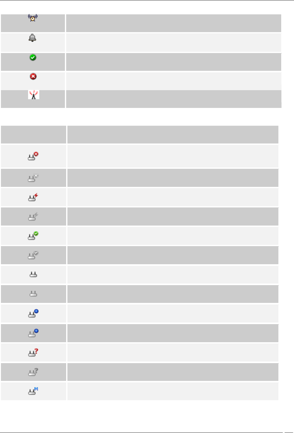
Appendix B:Glossary of Terms and Icons
SpectraGuard® Enterprise User Guide
333
Instantaneous: This icon indicates an instantaneous event that are triggered based
on a trigger that do not have continuity.
Expired: This icon indicates an expired event in which the triggers that raised the
event are not operational or have ceased to exist; this event has a valid start and
stop time stamp.
Secure: This icon indicates an event that does not contribute to the vulnerability
status of the system.
Vulnerable: This icon indicates an event that contributes to the vulnerability status of
the system.
Interference device/jammer icon: This icon shows the device which is RF Jammer or
source of non-Wi Fi interference
Devices Icons
Icon
Name: Description
Rogue AP-Active: This icon shows that a Rogue AP is active and visible to
Sensor(s).
Rogue AP-Inactive: This icon shows that a Rogue AP that was earlier visible to
Sensor(s) is inactive.
Mis-configured AP-Active: This icon shows that a Mis-configured AP is active and
visible to Sensor(s).
Mis-configured AP-Inactive: This icon shows that a Mis-configured AP that was
earlier visible to Sensor(s) is inactive.
Authorized AP-Active: This icon shows that an Authorized AP is active and visible to
Sensor(s).
Authorized AP-Inactive: This icon shows that an Authorized AP that was earlier
visible to Sensor(s) is inactive.
External AP-Active: This icon shows that an External AP is active and visible to
Sensor(s).
External AP-Inactive: This icon shows that an External AP that was earlier visible to
Sensor(s) is inactive.
Known External AP-Active: A Known External AP-Active is a recognizable external
device. For example an AP belonging to the neighboring organization could be
marked as a Known External AP.
Known External AP-Inactive: A known external AP-Inactive is a recognizable
external device. For example an AP belonging to the neighboring organization could
be marked as a Known External AP.
Indeterminate AP-Active: This icon shows that an Indeterminate AP is active and
visible to Sensor(s).
Indeterminate AP-Inactive: This icon shows that an Indeterminate AP that was
earlier visible to Sensor(s) is inactive.
Merged AP-Active: This icon indicates a merged AP is active and visible to
Sensor(s).
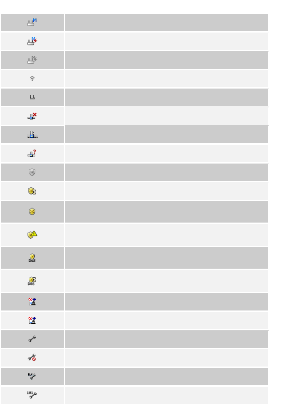
Appendix B:Glossary of Terms and Icons
SpectraGuard® Enterprise User Guide
334
Merged AP-Inactive: This icon shows that a merged AP that was earlier visible to
Sensor(s) is inactive.
Misconfigured Merged AP-Active: This icon shows that at least one BSSID in an
active merged AP is misconfigured
Misconfigured Merged AP-Inactive: This icon shows that at least one BSSID in an
inactive merged AP is misconfigured.
Single AP: This icon shows a radio for an AP.
Authorized Merge AP: This icon shows a merged AP (AP with mutliple BSSIDs).
Not plugged into your wired network: This icon shows that an AP is not connected
to your wired network.
Plugged into your wired network: This icon shows that an AP is connected to your
wired network.
Not sure if it is plugged into your wired network: This icon shows that an AP may
be connected to your wired network.
Not in Quarantine: This icon shows that the AP/Client is not in quarantine.
Quarantine Pending: This icon shows that the AP/Client needs to be quarantined,
but quarantine is pending.
Quarantined: This icon shows that the AP/Client has been quarantined. It can also
show that the AP is in port blocking.
Quarantine Error: This icon shows that some error has occurred while quarantining
a device.
DoS Quarantine: This icon shows that the quarantine against DoS attack on this
device is in progress.
DoS Quarantine Pending: This icon shows that the quarantine against DoS attack
on this device is pending.
Add to Banned List: This icon shows that the AP/Client has been added to the
Banned List.
Remove from to Banned List: This icon shows that the AP/Client has been removed
from the Banned List.
Troubleshooting: This icon shows that troubleshooting is in progress on a device.
Troubleshooting + Banned List: This icon indicates that the device is busy in
troubleshooting and is in Banned List.
Event Level Mode: This icon indicates that a troubleshooting session in event level
mode is in progress.
Packet Level Mode: This icon indicates that a troubleshooting session in packet
level mode is in progress.
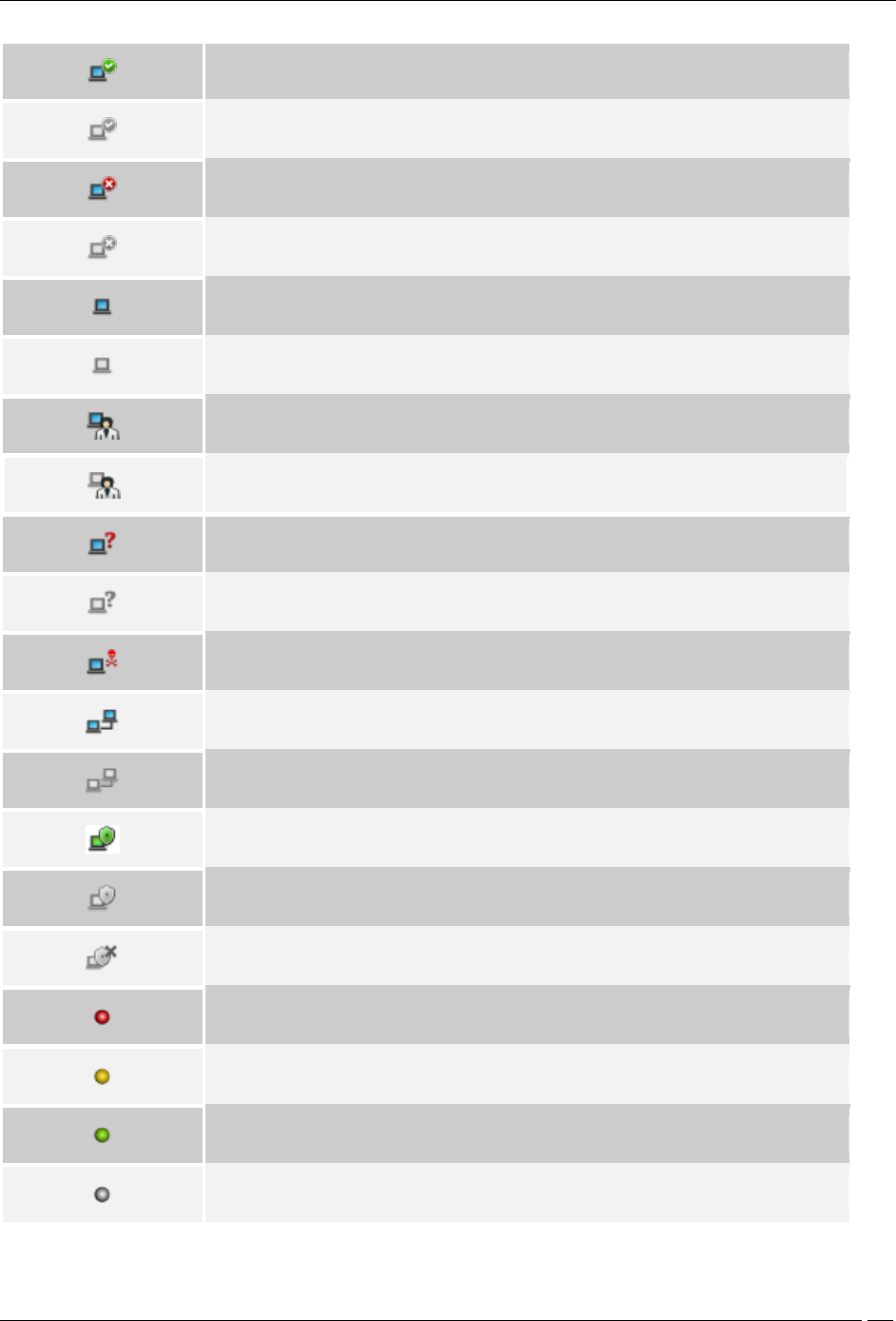
Appendix B:Glossary of Terms and Icons
SpectraGuard® Enterprise User Guide
335
Authorized Client-Active: This icon shows that an Authorized Client is active and
visible to Sensor(s).
Authorized Client-Inactive: This icon shows that an Authorized Client that was
earlier visible to Sensor(s) is inactive.
Rogue Client-Active: This icon shows that a Rogue Client is active and visible to
Sensor(s).
Rogue Client-Inactive: This icon shows that a Rogue Client that was earlier visible
to Sensor(s) is inactive.
External Client-Active: This icon shows that an External Client is active and visible
to Sensor(s).
External Client-Inactive: This icon shows that an External Client that was earlier
visible to Sensor(s) is inactive.
Guest Client-Active: This icon shows that a Guest Client is active and visible to
Sensor(s).
Guest Client-Inactive: This icon shows that a Guest Client that was earlier visible to
Sensor(s) is inactive.
Uncategorized Client-Active: This icon shows that an Uncategorized Client is active
and visible to Sensor(s).
Uncategorized Client-Inactive: This icon shows that an Uncategorized Client that
was earlier visible to Sensor(s) is inactive.
DoS Attacker: This icon shows the device from which the DoS attack is being
launched.
Client in Adhoc Mode-Active: This icon shows that a Client in adhoc mode is active
and visible to Sensor(s).
Client in Adhoc Mode-Inactive: This icon shows that a Client that was earlier in
adhoc mode and visible to Sensor(s) is inactive.
SAFE Installed-Active: This icon shows that SAFE is installed and active on the
Client.
SAFE Installed-Inactive: This icon shows that SAFE is installed but is inactive on the
Client.
SAFE Not Installed: This icon shows that SAFE is not installed on the Client.
SAFE Risk Level-High: This icon shows that SAFE is installed on the Client and the
risk level on that Client is high.
SAFE Risk Level-Medium: This icon shows that SAFE is installed on the Client and
the risk level on that Client is medium.
SAFE Risk Level-Low: This icon shows that SAFE is installed on the Client and the
risk level on that Client is low.
SAFE Risk Level-Not Known: This icon shows that SAFE is not installed on the Client
and hence the risk level is not known.
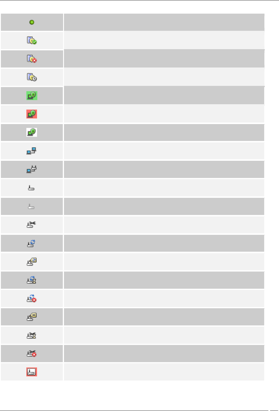
Appendix B:Glossary of Terms and Icons
SpectraGuard® Enterprise User Guide
336
SAFE Client-With Only Wired Interface: This icon shows a SAFE Client that has only
a wired interface.
SAFE Report Available: This icon indicates that a SAFE report generated earlier is
available for the selected Client.
SAFE Report Not Available: This icon indicates that a SAFE report is never
generated for the selected Client.
SAFE Report Scheduled: This icon indicates that a SAFE report will be generated for
the selected Client when it become active.
Authorized SAFE Client: This icon shows an Active Authorized SAFE Client.
Unauthorized SAFE Client: This icon shows an Active Unauthorized SAFE Client.
Uncategorized SAFE Client: This icon shows either an Active Uncategorized SAFE
Client or the absence of a Wireless Client.
This icon shows that a Client is connected to another Client.
Infrastructure Association: This icon shows that a Client is connected to an AP.
Sensor-Active: This icon shows that the Sensor is connected to the Server and is
actively monitoring the network. This Sensor has the latest software version and
does not need to be upgraded.
Sensor-Inactive: This icon shows that the Sensor is not connected to the Server
and is currently not monitoring the network. This Sensor has the latest software
version and does not need to be upgraded.
Sensor Repair In Progress: This icon shows that Sensor Repair is in progress.
Sensor Upgrade In Progress: This icon shows that Sensor Upgrade is in progress.
Sensor Upgrade Required: This icon shows that the Sensor needs to be upgraded
to a new version.
Sensor Upgrade Pending: This icon shows that the Sensor needs to be upgraded to
a new version and that the upgrade is pending.
Sensor Upgrade Failed: This icon shows that the Sensor upgrade to a new version
has failed.
Sensor Repair Required: This icon shows that the Sensor needs to be repaired as
the Sensor binaries are not updated.
Sensor Repair Pending: This icon shows that the Sensor needs to be repaired as
the Sensor binaries are not updated and that the repair is pending.
Sensor Repair Failed: This icon shows that the Sensor repair to a new binary
version has failed.
Sensor Indeterminate: This icon shows that the Sensor is in an indeterminate or
irrecoverable state.
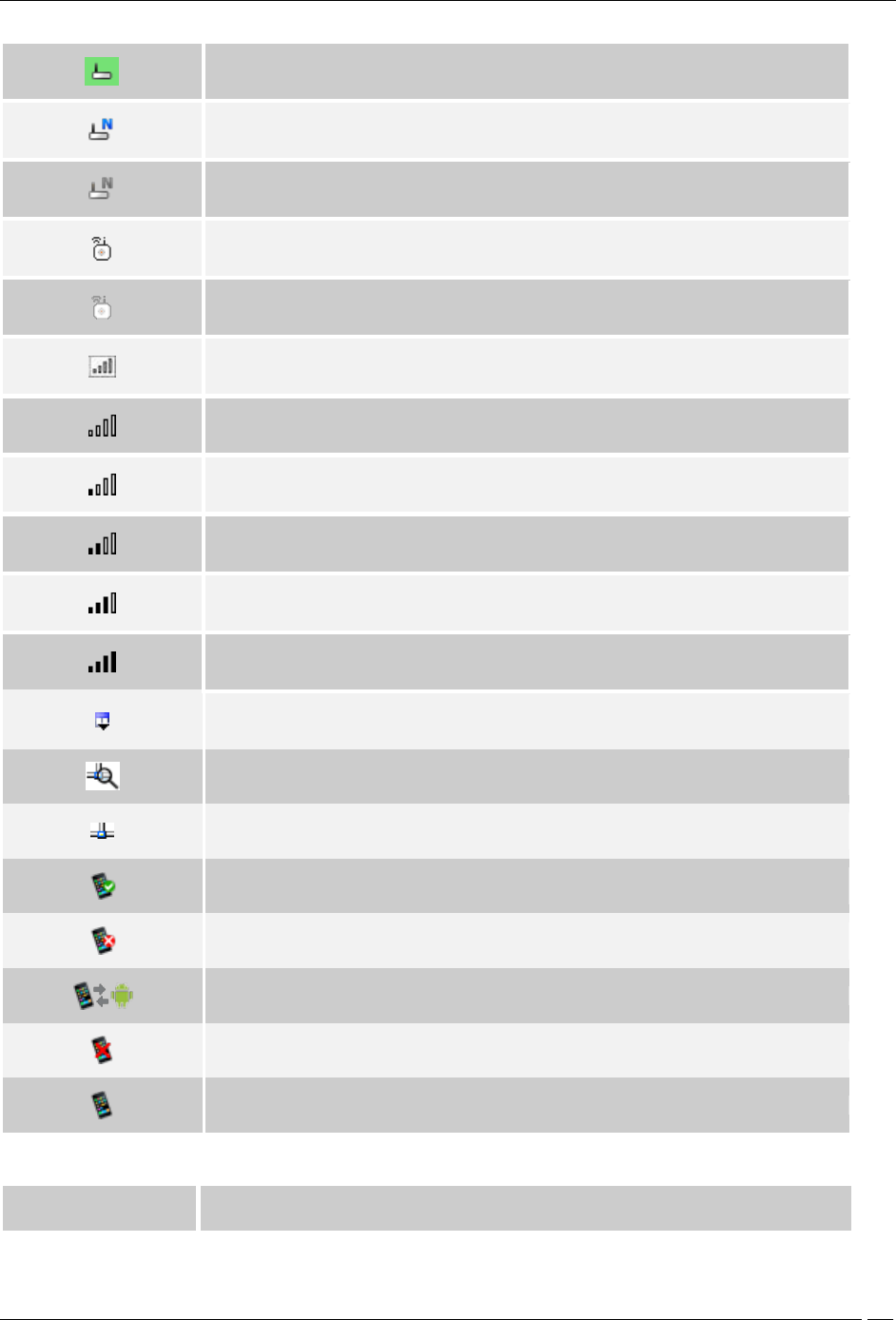
Appendix B:Glossary of Terms and Icons
SpectraGuard® Enterprise User Guide
337
Sensor Version Mismatch: This icon shows that the Sensor software version is
higher than that of the Server.
Network Detector-Active: This icon shows that the ND is connected to the Server
and is currently contributing into wired detection of APs.
Network Detector-Inactive: This icon shows that the ND is not connected to the
Server and is currently not contributing into wired detection of APs.
Sensor/AP Combo-Active: This icon indicates that the sensor/AP combo device is
connected to the Server and is monitoring the network.
Sensor/AP Combo-Inactive: This icon indicates that the sensor/AP combo device is
connected to the Server and is inactive.
RSSI: This icon shows signal strength observed by reporting device for AP or
Client.
RSSI Level 0: This icon shows very low signal available.
RSSI Level 1: This icon shows low signal strength.
RSSI Level 2: This icon shows medium signal strength.
RSSI level 3: This icon shows strong signal strength
RSSI Level 4: This icon shows very strong signal strength.
Display Columns: Most fields in the table can be selected for display or optionally
hidden. This button allows selection and configuration of parameters to show and
hide in the table.
Monitored Network: This icon indicates that the network is being monitored by a
sensor.
Unmonitored Network: This icon indicates that the network is not being monitored
by a sensor.
Approved Smart Device: This icon indicates that the authorized client is an
approved smart device.
Unapproved Smart Device: This icon indicates that the authorized client is an
unapproved smart device.
Change Device Type: This icon indicates a change in the smart device type.
Not a Smart device: This icon indicates that the client is not a smart device.
Smart Device: This icon indicates that the guest client is a smart device.
Locations Icons
Icon
Name: Description
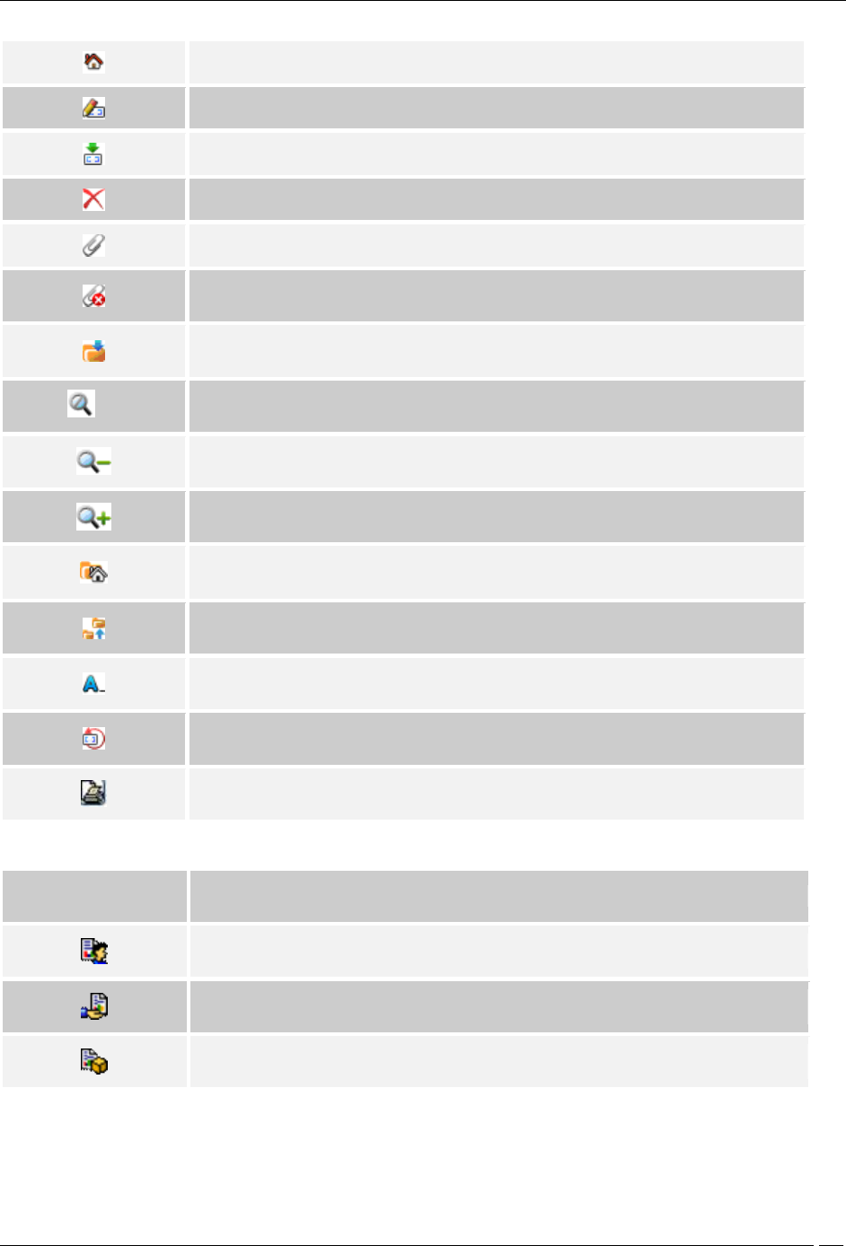
Appendix B:Glossary of Terms and Icons
SpectraGuard® Enterprise User Guide
338
Add Location: The button with this icon allows you to create a new location folder or
node.
Edit Properties: The button with this icon allows you to edit the properties of the
existing location folder or node.
Import Location: The button with this icon allows you to import a file in .SPM format
for a specific location from a specified path.
Delete: The button with this icon allows you to delete selected item/entity.
Attach Image on floor: The button with this icon allows you to attach an image to
location folder or node.
Detach Image: The button with this icon allows you to detach an image from
location folder or node.
Save: The button with this icon allows you to save the changes made to the current
Locations screen.
Best Fit: The button with this icon allows you to fit the layout image to the
window/page.
Zoom Out: The button with this icon allows you to zoom out of a layout image.
Zoom In: The button with this icon allows you to zoom into a layout image for an
enlarged view
Unknown: This icon signifies the default location folder of the root location. When
the system detects a new untagged device, the device is tagged to the Unknown
location folder.
Move: This icon in the context-sensitive menu on the Locations screen indicates that
you can move a location folder or node to another location in the Location tree.
Rename: The button with this icon allows you to rename the selected location
node/folder.
Reset Canvas: The button with this icon allows you to revert to a blank canvas.
Printable View: The button displays the currently active information of selected
location information/RF view
Reports Icons
Icon
Name: Description
My Reports: This icon indicates a report that only a single user, the one who created
the report, can view it.
Shared Reports – Custom Reports: This icon indicates a Shared report that all users
can view.
Shared Reports – Pre-defined Reports: This icon indicates reports that are pre-
defined and can be viewed by all users.
Administration Icons
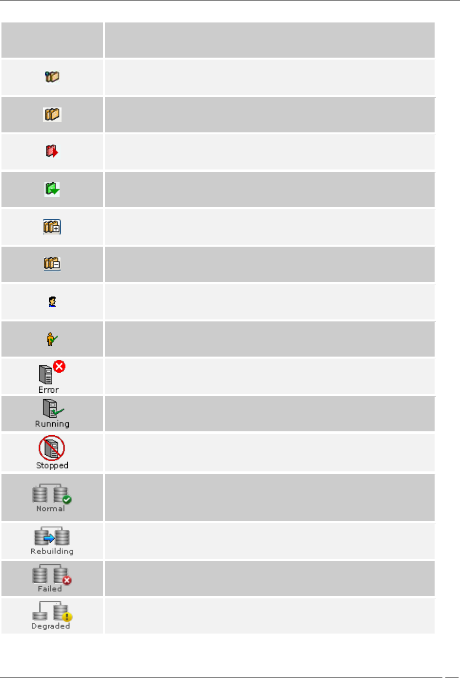
Appendix B:Glossary of Terms and Icons
SpectraGuard® Enterprise User Guide
339
Icon
Name: Description
Global Policies: The button with this icon indicates policies that are applicable to all
the locations defined in the system.
Local Policies: The button with this icon indicates policies that are specific to a
particular location defined in the system.
Custom Defined Policy: This icon signifies a policy group whose policies are custom
defined.
Inherited Policy: This icon signifies a policy group whose policies are inherited.
Expand All: The button with this icon enables you to expand all the nodes, there
allowing you to view all the nodes in the Administration tree.
Collapse All: The button with this icon enables you to collapse all the nodes, there
preventing you to view all the nodes in the Administration tree.
Local User: This icon indicates a system user.
LDAP User: This icon indicates an LDAP user.
Server Error or Integration Failure: This icon shows that an error has occurred in
the Server or ESM/WLAN Integrations.
Server or Integration Running: This icon shows that the Server or ESM/WLAN
Integration is functioning normally.
Server or Integration Stopped: This icon shows that the Server or ESM/WLAN
Integration has stopped functioning.
Hard disk redundancy on SA-350 appliance is supported by RAID-1 Array with two
Hard disks. Data is mirrored on both Hard disks simultaneously.
RAID Normal: Indicates that RAID Array is in normal operating state.
RAID Rebuilding: This is a transient state. It indicates that data is being
synchronized from one Hard disk to the other. System services operate in normal
state when RAID Array is rebuilding.
RAID Failed: Indicates that RAID Array has failed and can not be recovered
automatically. Please contact Technical Support. System services may not operate
in normal state when RAID Array has failed.
RAID Degraded: Indicates that RAID Array has degraded and is not able to
synchronize data from one Hard disk to the other. System services operate in
normal state, but Hard disk redundancy is not available in this state.