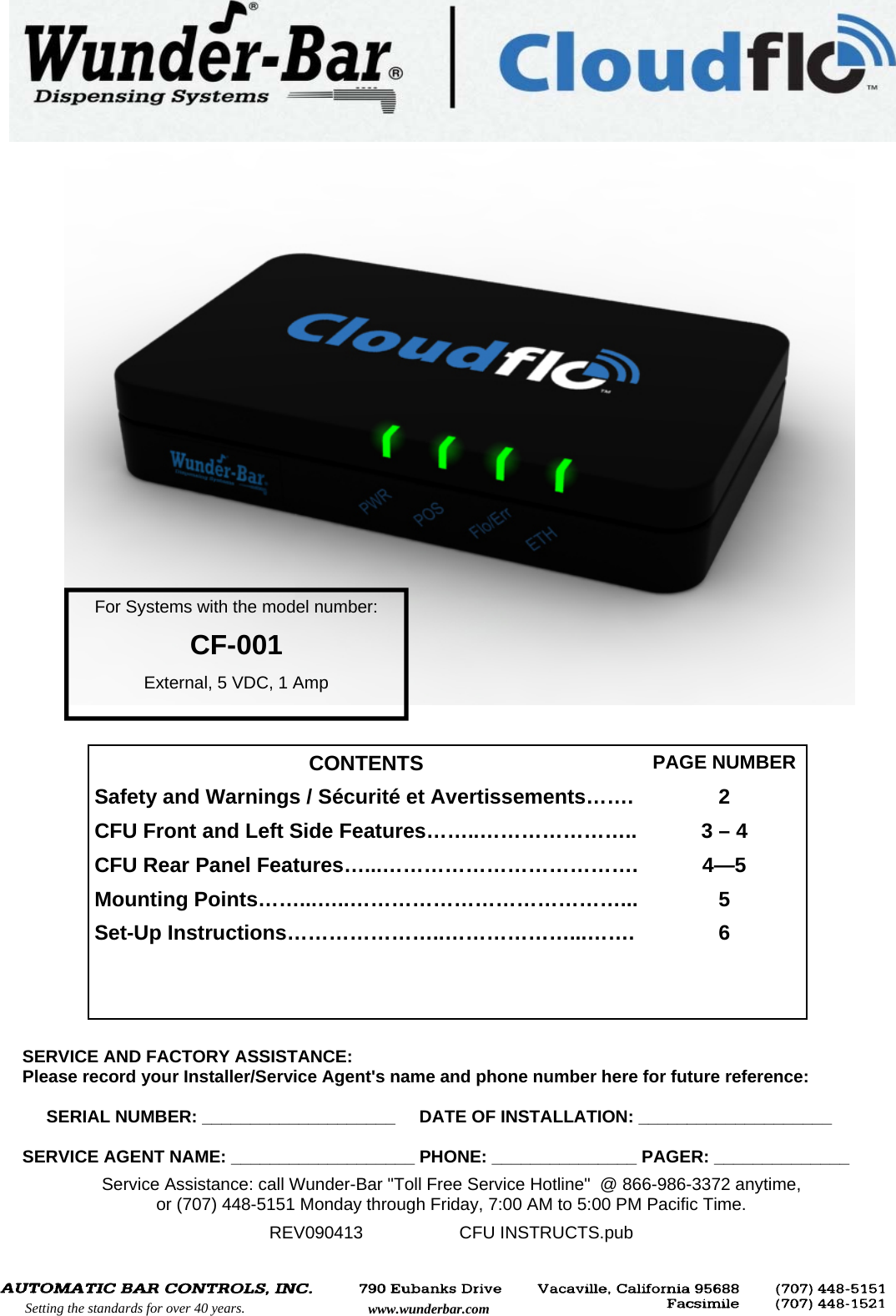
Automatic Bar Controls CF001 Beverage Dispensing Data Collection User Manual CFU INSTRUCTS 09 04 13 pub

Automatic Bar Controls, Inc. Beverage Dispensing Data Collection CFU INSTRUCTS 09 04 13 pub

Users Manual

  SERVICE AND FACTORY ASSISTANCE:                                         Please record your Installer/Service Agent's name and phone number here for future reference:       SERIAL NUMBER: ____________________     DATE OF INSTALLATION: ____________________  SERVICE AGENT NAME: ___________________ PHONE: _______________ PAGER: ______________  Service Assistance: call Wunder-Bar "Toll Free Service Hotline"  @ 866-986-3372 anytime,  or (707) 448-5151 Monday through Friday, 7:00 AM to 5:00 PM Pacific Time.  REV090413                    CFU INSTRUCTS.pub  CONTENTS  PAGE NUMBER Safety and Warnings / Sécurité et Avertissements…….  2 CFU Front and Left Side Features……..…………………..  3 – 4 CFU Rear Panel Features…...……………………………….  4—5 Mounting Points……...…..…………………………………...  5 Set-Up Instructions…………………..………………...…….  6     For Systems with the model number:    CF-001   External, 5 VDC, 1 Amp        Setting the standards for over 40 years.  www.wunderbar.com
         Setting the standards for over 40 years.  www.wunderbar.com 2 This Instruction Manual describes the different hardware functionalities of the Cloudflo® Unit (CFU).  The CFU is the main component of the Cloudflo® System.  It receives wireless messages from external RF wireless devices like Skyflo® Spouts and Beerflo® meters.  It stores pour data, and enables a remote system to retrieve and generate informative reports.  This Instruction Manual is intended to provide a technician/installer/manager the ability to learn about the CFU’s physical attributes and functions to assist with installation, operation, and maintenance.  ATTENTION! •  Read all Instructions before setting up or operating the CloudFlo® Unit. Install and use the CloudFlo® Unit only as described in this instruction manual. Use only the manufacturer’s recommended power supply, cables, and accessories. •   Always disconnect the power supply from the electrical source before removing the CloudFlo® Unit cover or attempting any servicing of internal parts or components.  •  Do not operate the CloudFlo® Unit if the power supply has been damaged, if the power supply has a damaged cord, or if the CloudFlo® Unit has been damaged – until any damage has been examined by a qualified CloudFlo® service technician.  •  The CloudFlo® Unit should never be exposed to or sprayed with excess water or moisture. Clean with a damp cloth, only.  •  There are no End-User serviceable parts or components inside the CloudFlo® Unit enclosure.  The CloudFlo® Unit’s cover should only be removed by, and internal parts and components serviced by a qualified service person with the knowledge, experience, and training for servicing of the CloudFlo® Unit.  •  The CloudFlo Unit should be operated in these ambient temperatures: MIN: 36° F, 2° C  MAX: 104° F, 40° C •  IMPORTANT! Changes or modifications not expressly approved by Automatic Bar Controls, Inc could void the user’s authority to operate the equipment.  •  Lisez toutes les instructions avant d'installer ou de faire fonctionner l'unité CloudFlo®. Installez et utilisez l'unité CloudFlo® uniquement comme décrit dans ce manuel d'instruction. Utilisez seulement recommandé alimentation, les câbles et les accessoires du fabriquant.  •  Toujours débrancher l'alimentation de la source électrique avant de retirer le capot de l'unité CloudFlo® ou de tenter toute réparation de pièces ou de composants internes. •  Ne pas faire fonctionner l'unité CloudFlo® si l'alimentation a été endommagé, ou si l'alimentation a un cordon endommagé, ou si le CloudFlo® appareil a été endommagé - jusqu'à ce que tout dommage a été examiné par un technicien qualifié. •  L'Unité CloudFlo® ne doit jamais être exposé ou pulvérisé avec de l'eau en excès ou à l'humidité. Nettoyer avec un chiffon humide seulement. •  Il n'y a aucune pièce réparable par l'utilisateur final ou de composants à l'intérieur de l'enceinte de l'unité CloudFlo®. La couverture du CloudFlo® Unité ne doit être retiré par, et ses composants internes que par un personnel de service qualifié les connaissances, l'expérience et la formation pour l'entretien de l'unité CloudFlo®. •  IMPORTANT! Les changements ou modifications non expressément approuvés par les contrôles automatiques de barres, Inc pourraient annuler l'autorité de l'utilisateur à utiliser l'équipement. FCC Statement: The CloudFlo Unit complies with Part 15.19 of the FCC rules. Operation is subject to the following two conditions: (1)  This device may not cause harmful interference. (2)  This device must accept any interference received, including interference that may cause undesired operation.  Canadian IC Statement: The CloudFlo Unit complies with the Industry Canada license– exempt RSS standard(s).  Operation is subject to the following two conditions: (1)  This device may not cause harmful interference. (2)  This device must accept any interference received, including interference that may cause undesired operation.  CloudFlo Unit  M/N: CF-001 FCC ID: 2AAVJ-CF001  IC ID: 11358A-CF001   Note: This equipment has been tested and found to comply with the limits for a Class B digital device, pursuant to part 15 of the FCC Rules. These limits are designed to provide reasonable protection against harmful interference in a residential installation. This equipment generates, uses and can radiate radio frequency energy and, if not installed and used in accordance with the instructions, may cause harmful interference to radio communications. However, there is no guarantee that interference will not occur in a particular installation. If this equipment does cause harmful interference to radio or television reception, which can be determined by turning the equipment off and on, the user is encouraged to try to correct the interference by one or more of the following measures: —Reorient or relocate the receiving antenna. —Increase the separation between the equipment and receiver. —Connect the equipment into an outlet on a circuit different from that to which the receiver is connected. —Consult the dealer or an experienced radio/TV technician for help. This Class B digital apparatus meets all requirements of- the Canadian Interference-Causing Equipment Regulations. Cet appareil numérique de la classe B respecte toutes les exigences du Réglement sur le matériel brouilleur du Canada.
         Setting the standards for over 40 years.  www.wunderbar.com Ethernet Status Data Flow Status POS Data Flow Status Power USB Backup Port  Data Export Button Data Alarm Button OFF  CFU power is OFF  GREEN  Steady green when the CFU is powered on and is connected to external 5V power supply  RED  Steady red when the CFU is powered on and running on internal battery  LED1: PWR  OFF  No serial line activity GREEN  Blinks green every time a data packet is sent to the POS system RED  Blinks red when a NACK is received from the POS or a communication error occurs LED2: POS  OFF  No RF radio activity GREEN  Blinks green every time a radio packet is sent or received to/from the field devices RED  Blinks red when the internal buffer is almost* full, indicating data needs to be exported   LED3: Flo/Err OFF  No Ethernet connection GREEN  Steady green when an Ethernet connection is detected (active network cable is attached)  YELLOW  Blinking yellow every time a data packet is sent or received on the Ethernet interface LED4: LAN  USB PORT  Insert USB memory device before pressing Data Export Button  BACKUP BUTTON  Push button to trigger data export procedure to a USB memory device attached to USB port  ALARM MUTE BTN  Press to silence “data full” alarm buzzer for a period of time. The alarm buzzer will sound again if data has not been exported after a period of time. (see alarm functions on page 4) CFU LEFT SIDE: USB BACKUP PORT AND BUTTONS  * The threshold of empty space available that triggers this condition can be configured in the software. 3 FRONT AND LEFT SIDE PANELS
  REAR PANEL Antenna Power Input RS-232 Port  Reset/Update Button Ethernet Ports Antenna USB Service Port        Setting the standards for over 40 years.  www.wunderbar.com 4 Shutdown in progress  When the power supply is disconnected from the CFU, one short beep will be emitted and the CFU will begin an automatic shut-down procedure. Available buffer space below Threshold  When the internal data storage is almost full, the alarm starts beeping every two seconds to signal the need to export data (to an attached PC or memory device).  The alarm stops beeping when data is successfully exported or after the alarm is silenced by pressing the Alarm Mute Button (see page 3, ALARM MUTE BTN). Data export in progress  One short beep is emitted when an export procedure, to a USB memory device, is started. When the data export is completed, two short beeps are emitted.  If an error occurs during the export, one long beep is emitted. ALARM FUNCTIONS   FRONT AND LEFT SIDE PANELS (Continued) REAR PANEL FEATURES   Twin RF Antennas  Two RF antenna masts are included with the CFU. Install an antenna onto both of the Antenna mounts and hand-tighten by nut to the right (clockwise).  Do not attempt to operate with only one antenna as CFU performance will be dramatically reduced.  Power Input  Attach the 100—240 VAC to 5 VDC Power Supply that was provided with the CFU by fully inserting the Power Supply’s connector into the CFU’s PWR socket.    RS-232 Port  For “Front of the House” POS interfacing.  RS-232 port is a standard D-sub 9pin male connector (DB-9 / DE-9M). Dual LAN Ports  Two 10/100Mbit Ethernet ports on RJ-45 standard connectors. Either of these two ports can be used for the purposes of interfacing with the CFU.  Additionally, the port not in use can be used as a “switch” port for another CFU and to “Daisy Chain” CFU’s.  An example of the use of this capability would be a possibility that a bar location could have 2-3 POS systems, but only one network cable available to the Bar.  The main cable that makes the network available could be plugged into a CFU.  The other CFU’s could link back across the same “main cable” through the use of the “Daisy Chain” between CFU’s.
         Setting the standards for over 40 years.  www.wunderbar.com 5 RESET / UPDATE BUTTON  Hardware Reset  In the unlikely event of an CFU embedded firmware crash: FIRST:  Press and hold the Reset/Update Button for more than 7.5 seconds while the                       CFU is running and the CFU software will reset, regardless of its logic state.    SECOND: If a Reset/Update attempt does not correct the problem, unplug the CFU and                    wait for the internal battery to deplete completely (the PWR indicator light will                   be steady red until all battery power is depleted). When the red PWR light goes                   out, attach the power supply to restart the CFU.  Factory Restore  To restore the CFU's embedded firmware, power up the CFU. After 5 seconds the LED2, LED3 and LED4 will go through this sequence, where 1 is green light, cycling every second:       1.  1 0 0           2.  1 1 0         3.  1 1 1      4.  0 1 1      5.  0 1 1    During this sequence press and hold the Reset/Update button, the same sequence will occur with red light. A couple of seconds after the sequence, the three leds will start flashing independently, indicating the factory restore procedure is in progress.  Once initiated, the restore procedure must not be interrupted or the CFU may require servicing. WARNING: All stored data and configuration information are irreversibly deleted during the Factory Restore process. REAR PANEL (Continued) MOUNTING POINTS  Two mounting points are located on the underside of the CFU (see red squares). The CFU my be secured to a horizontal or vertical surface using two (2) #8 pan head screws that are specific to the material the CFU is to be mounted to.
  SET-UP INSTRUCTIONS SET-UP  FIRST  Attach both antennas to the CloudFlo® Unit and tighten the Antenna Mounting Nuts until they are finger tight. Do not over-tighten the Antenna Mounting Nuts using a pliers or damage may result. FOURTH  Make sure that your PC or MAC is set-up to receive an IP address over DHCP. THIRD  Wait about two minutes for the CloudFlo® Unit to “boot up” and load all operation files.  SECOND  Connect the Power Supply to the CloudFlo® Unit by inserting the Power Supply’s plug into the rear panel socket labeled PWR. (see page 4 of this manual)  SIXTH  On your PC or MAC: Open a browser and go to http://192.168.0.14 to configure your CloudFlo® System.   NOTE: Your PC or MAC must also have a unique IP address and exist on the same                 subnet as: 192.168.0.14.  For example: 192.168.0.15.  FIFTH  Use a network cable to connect your PC or MAC to either one of the LAN ports located on the rear panel of the CloudFlo® Unit. (see page 4 of this manual)

Navigation menu