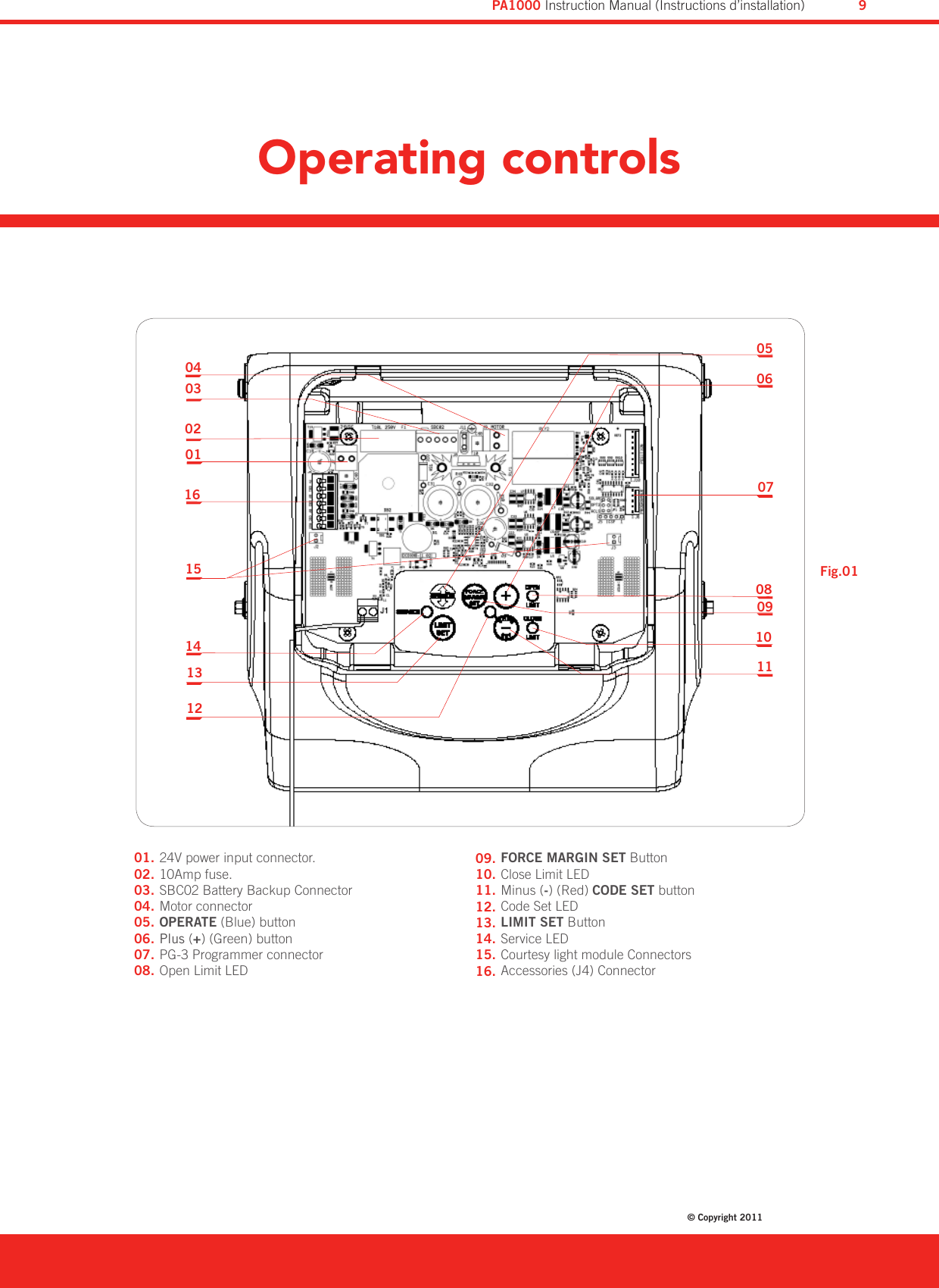
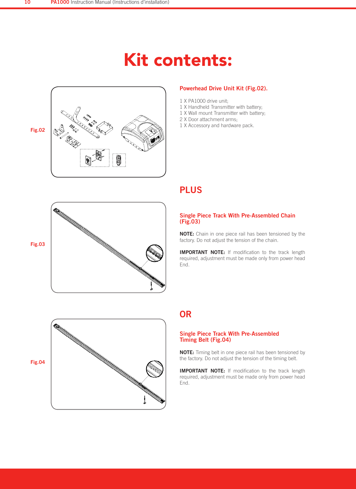
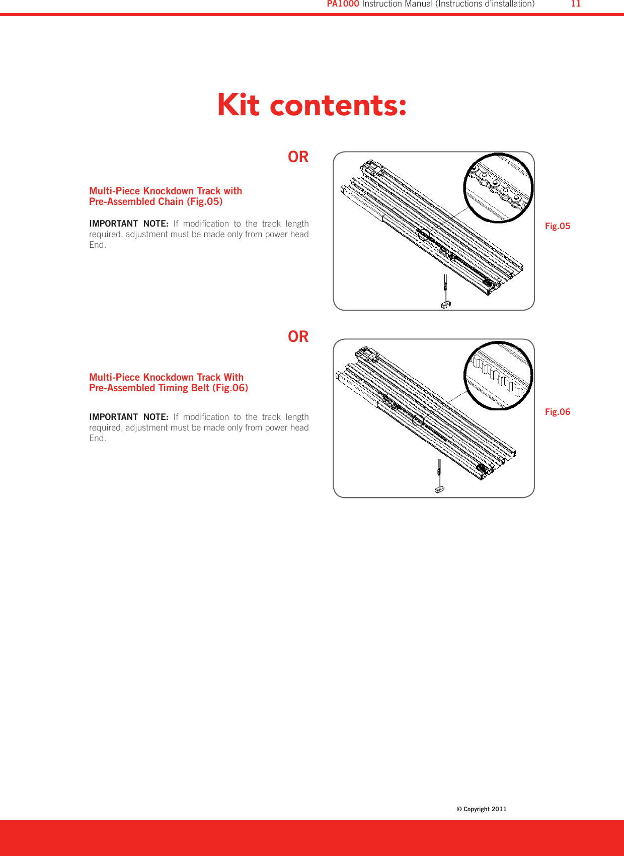
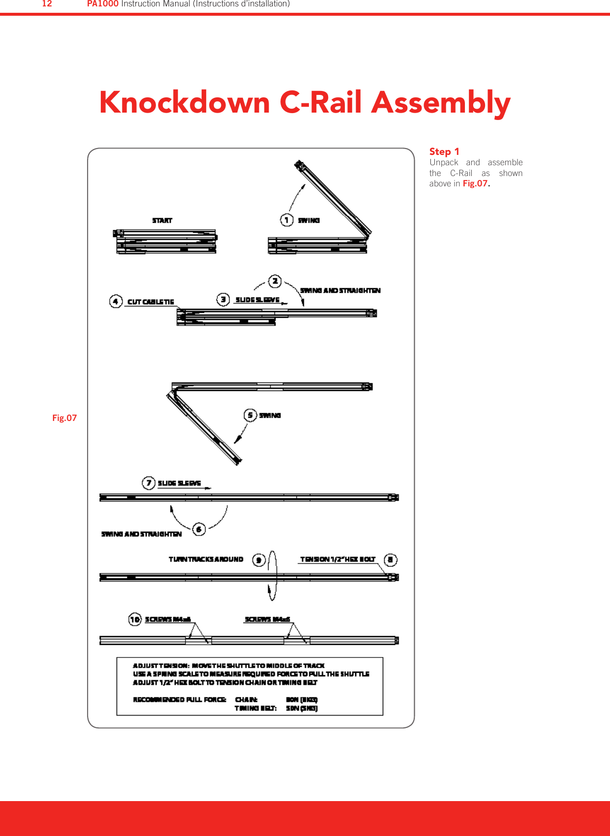
Automatic Technology PAPTX5V101 PTX-5V1 REMOTE CONTROL TRANSMITTER User Manual 3

Automatic Technology (Australia) Pty. Ltd. PTX-5V1 REMOTE CONTROL TRANSMITTER Users Manual 3

Contents

Users Manual 3

www.bnd.com.auPart Number #40020Model: PA1000V1October 2011 FOR RESIDENTIAL USE ONLYInstruction Manual(Notice D’exploitation)PA1000 - Overhead Garage Door Operator
WARNING:  It  is  vital  for  the  safety  of  persons to  follow  all  instructions.  Failure  to  comply with the installation instructions and the safety warnings  may  result  in  serious  personal  injury and/or  property  and  remote  control  opener damage.  Please  save  these  instructions  for future reference.AVERTISSEMENT: pour la sécurité des usagers, il est essentiel de suivre toutes les instructions. Le non- respect des instructions d’installation et des avertissements de sécurité peut causer de graves blessures et/ou endommager l’appareil et  la  télécommande.  Veuillez  conserver  ces instructions pour future référence.To  reduce  the  risk  of  electric  shock,  this equipment has a grounding type plug that has a third (grounding) pin. This plug will only fit into a grounding type outlet. If the plug does not fit into  the  outlet,  contact  a  qualified  electrician to install the proper outlet. Do not change the plug in any way.Pour reduire les risques de choc electrique, cet appareil  est  quipe  d’une  fiche  avec  mise  a  la terre comportant une troisieme broche (broche deterre). Cette fiche ne peut etre branche que dans  une  prise  avec  mise  a  la  terre.  S’il  n’est pas possible de la brancher dans la prise, faire poser  une  prise  appropriee  par  un  electricien qualifie. Ne pas modifier la fiche.
Safety Rules                05System Specications                06Default Settings and Technical Specication               06About Your Operator                07Operating Controls                08Kit Contents                 10Installation                     Knockdown C-Rail  Assembly                 12     C-Rail  Assembly                 13     Mounting Operator for Track Type Door               14     Mounting Door Bracket & Arms                15     Safety Beam Installation                15Setting Speed and Limits                     Setting Speed Mode                17     Setting Limits Position                18Testing Safety Obstruction Force          19Setting Safety Obstruction Force                20Coding Transmitters                     Door                21     Courtesy Light                21     Vacation Mode                22     Auxiliary Output                22     Pet Mode                23     Erasing Transmitter Codes                23     Mounting Wall Transmitter                 23Accessories                  Terminal Block                24  Remote Aerial                 24  Wired Wall Switch / Key Switch                24        Battery Back Up Installation                25CONTENTSPA1000V1 Overhead Garage Door OperatorDiamond PD Power Drive : Instruction Manual© Copyright 20113PA1000 Instruction Manual (Instructions d’installation)
How to Use Your Operator                  Remote Control Transmitter                 26  In-Build Locking                 27  Manual Door Operation                 27  Power Failure                27  Removing Transmitter Battery                 27  Safety Beam Option                28  Auto-Close Option                28  Courtesy Light                 28  Auxiliary Output                 28  Vacation Mode                 28  Pet Mode                 28  Service                 28Maintenance                 29Troubleshooting Guide                 30Parameters                31Spare Parts List                 32Warranty                 34Optional Accessories                 36CONTENTSPA1000V1 Overhead Garage Door OperatorPA1000 Instruction Manual (Instructions d’installation)4
Safety Rules (Les règles de la sécurité)Please read these important safety rulesThese  safety  alert  symbols  indicate  a  personal  safety  or  property  damage instruction exists. READ THESE INSTRUCTIONS CAREFULLY. This automatic garage door operator is designed and tested to offer safe service provided  it  is  installed  and  operated  in  strict  accordance  with  the  following safety rules. Failure to comply with the installation instructions and the safety warnings may result in death, serious personal injury and/or property damage.CAUTION: If  your  garage  has  no  pedestrian  entrance door, an emergency access device should be installed. This  accessory  allows  manual  operation  of  the  garage door from outside in case of power failure.Position the Garage Door Operator so that the power plug is accessible when inserted into the power outlet.This opener should be installed in accordance with relevant US and Canada Standards.Do not allow children to play with door controls.Keep transmitters away from children. Watch the  moving  door  and  keep  people  away  until  the door is completely opened or closed.Activate the operator only when the garage door is in full view,  free of  obstructions  and  with  the  opener  properly adjusted.Keep the garage door balanced. Sticking or binding doors must be repaired. Garage doors, door springs, brackets and their hardware are under extreme tension and can cause serious personal injury. Do not attempt any garage door adjustment. Do not use if repair or adjustment is needed. Call for professional garage door service.Install the wall transmitter in a location where the garage door is visible, but out of the reach of children at a height of at least 5 feet (1.53m). Disconnect  electric  power  to  the  garage  door  operator before removing covers.Door must have Safety Beams tted.Do not wear  rings,  watches  or  loose clothing  while installing or servicing a garage door operator.This operator is not suitable for commercial, industrial or common entry applications.To  avoid serious personal injury from entanglement, remove all unnecessary ropes or chains and disable any equipment such as locks which are not needed for powered operation.Installation  and wiring must  be  in  compliance  with your  local  building  and  electrical  codes.  Connect the power cord only  to  properly  earthed mains. If an extension lead must be used, make sure it is a 3-core lead and approved to 7 amp capacity.To reduce the risk of electric shock, this equipment has a earthing type plug that has a third (earthing) pin. This plug will only t into a earthing type outlet. If  the  plug  does  not  t  into  outlet,  contact  a  qualied electrician to install the proper outlet. Do not change the plug in any way.If  the  power  cord  is  damaged,  it  must  be  replaced by the manufacturer, its service agent or a similarly qualied person in order to avoid a hazard.This operator is a plug in domestic appliance and is designed for indoor use only. It must be installed in a dry position that is protected from the weather. The opener is not intended for use by young children or inrm persons without supervision.WARNING!  It  is  vital  for  the  safety  of persons  to  follow  all  instructions.  Save these instructions.Diamond PD Power Drive : Instruction Manual© Copyright 20115PA1000 Instruction Manual (Instructions d’installation)
System SpecificationsFactory Default SettingsDefault Step MaximumMaximum motor run time 30 Secs. - -Courtesy light time 3 Mins. approx. - -Obstruction force margin 2 1 14Auto close time 30 Secs - -Technical SpecificationsInput Voltage 120Vac / 60HzFuse (primary) 1.3A (slow blow)Input power (max) 200 WattsStandby power, less than 2 WattsTransformer secondary output Voltage 24VacMotor type 24Vdc geared motor with permanent magnetShuttle travel distance in the C-Rail 9.19ft (2.8m) approximately (standard)Maximum shuttle travel distance in the C-Rail 16.4ft (5m) (with extended C-Rail)Maximum door area 177sq.ft (16.5 m2)Maximum door hanging weight 441lbs (200kg)Receiver type UHF Multifrequency FM-ReceiverReceiver code storage capacity 14 X 4 button transmitter codesTransmitter frequency 433.47MHz; 433.92MHz; 434.37MHz Coding type TrioCode™Number of code combinations Over 4.29 billion random codesCode generation Nonlinear encryption algorithmRemote control battery CR2032   3 VoltsCourtesy light 2 LED ModulesController fuse 10A (slow blow)NOTE: Intermittent operations may occur in areas which experience very strong winds. The strong wind puts extra pressure on the door and tracks which may in turn trigger the safety obstruction detection system intermittently.PA1000 Instruction Manual (Instructions d’installation)6
Thank you for choosing a PA1000 automatic garage door operator.The  technically  advanced  construction  of  this  operator ensures you enjoy the following benets:Warrantyxxx  (x)  years  /  xxxx  cycles  full  parts  and  labour  warranty on motor, electronics and mechanical components of the operator  when  installed  by  a  garage  door  professional (conditions such as annual garage door servicing apply).TrioCode™ Frequency Hopping TechnologyEvery time a transmitter is used, it simultaneously sends  a signal over three different frequencies, reducing the chance of interference from other radio frequency sources.Code Hopping TechnologyEvery  time  a  transmitter  is  used  a  new  security  code is  generated  from  over  4.29  billion  possible  code combinations.  This  greatly  enhances  the  security  of  the system and makes “code grabbing” a thing of the past!Multi-Channel TransmitterMulti-channel  transmitters  allow  you  to  operate  other devices  such  as  an  adjoining  garage  door  or  automated gate from the same handy unit.Warranty Expired IndicatorThe  operator  will  indicate  that  the  number  of  cycles covered by the warranty has been reached by ashing the courtesy light 10 times after each operation.  This ashing will continue for 20 cycles unless it is reset by pressing the SET button while the courtesy light is ashing.S-ALPS  (Semi  Automatic  Limits  Positioning System)The S-ALPS system does away with manual adjustment of the door’s limits position using mechanical parts, such as cams and microswitches. Safety Reversing SystemThe automatic safety reverse system signicantly reduces the risk of  death or serious injury if trapped by a closing door. The safety reverse force can be adjusted for environmental conditions such as windy areas.Safety Infra-Red Beam ProtectionThe  Safety  Beam is  the  infrared  (IR)  invisible  light  beam system  which  shall  protect  the  doorway.  The  door  stops and reverse to the full position if anything passes through the beam. Soft Start/Soft StopThe  operator  eases  into  and  out  of  an  operating  cycle.  This  makes  operation  smoother  and  quieter  and  most  importantly  reduces  wear  and  tear  on  the  door  and operator.Courtesy LightThe  courtesy  light  automatically  switches  on  for approximately three (3) minutes when operating the door. This can also be programmed to turn on and off from a transmitter.Memory RetentionIn case of a power failure, the operator does not lose the transmitter codes or limit settings. Soft Start/Soft StopThe opener eases into and out of each cycle making for smoother and quieter operation, as well as reducing wear and tear on the door and operator.Manual ReleaseThe  manual  release  handle  allows  the  door  to  be operated by hand in the event of a power failure.Self LockingThere is no need to manually lock your garage door, as the operator ‘positively’ locks the door when closed.Periodic Maintenance Indicator The  SERVICE  LED  will  illuminate  to  indicate  that periodic maintenance is required. Contact your garage door professional  for service. Service Fault IndicatorFlashing  LEDs  on  the  control  panel  easily  identify operational problems or service requirements.Dynamic Door ProlingChanging  door  characteristics  are  automatically compensated for and “learnt” with each operation of the door.External AerialAn  external  aerial  can  be  connected  for  sites  where radio reception is a problem.Vacation ModeA  transmitter  can  be  programmed  to  disable  the garage door operator radio receiver. This is ideal if the door is to be left idle for prolonged periods.Pet (Pedestrian) ModeA  transmitter  can  be  programmed  to  open  the  door partially  to  allow  pets  access  to  the  garage.  The  door opening height is adjustable via a handheld programmer.Auxiliary OutputYou can program a spare button on your transmitter to operate this output, which can control items that use a momentary close switching mechanism.About Your OperatorDiamond PD Power Drive : Instruction Manual© Copyright 20117PA1000 Instruction Manual (Instructions d’installation)
Operating controlsTerminal is used to connect Vac to the control board.10 Amps fuse to protect the electronic circuit board.This  connector  is  used  to  connect  Battery  Charger SBC02 to the opener.DC 24V motor connects to this connector.Operate (blue) Button is used during installation to test the  open,  stop  and  close  cycles  for  the  opener.  The opener has to be initialised by the Limit set button before the Operate Button becomes operable.Plus  (+)  Green  Button    is  used  during  installation  to help  set  the  open  limit  position.  Pressing  and  holding this  button  will  move  the  door  in  the  open  direction. Movement stops when the button is released.Prog input is used to connect a PG-3 Programmer for editing  functions,  diagnostic  purposes  and  accessing special features.  Open Limit (Green) LED illuminates and ashes when the  door  is opening and remains steady on  when the open limit position has been reached.Force Margin Set The obstruction force pressure is set automatically  by  the  opener  during  installation.  The pressure  can  be  adjusted  manually  using  the  Force Margin Set Button. Holding the Force Margin Set Button and pressing the Plus (+) or Minus (-) Button will increase or decrease the amount of force. The force margin set is only  ever used  if other  environmental  factors  (wind, etc..) Affect the operations of the door/opener.Close Limit Red LED illuminates and ashes when the door is closing  and  remains steady on  when  the close limit position has been reached.Minus (-) Red Code Set Button is used during installation to help set the close limit position. Pressing and holding this  button  will  move  the  door  in  the  close  direction. Movement stops when the button is released.Code Set LED light ashes when a code is being stored or when a transmitter button is pressed.Limit  set  Button  is  used  during  the  installation  phase together with the open and close buttons to set the door limit positions. The  Limit  set button is  also  used to re-initialise the opener. Service LED (yellow) indicates when the opener requires service or repairs.Courtesy  LED  Light  Module  Connectors  are  used  to connect +24V LED light modules.Terminal Block (J4): V+ (+35V/+24V) is used to power Accessories such as external receiver (200mA max).EB1 (mandatory) input is used to connect to Safety Beam.0V is a 0 volt connection for Safety Beam.EB2 input is used to connect to Safety Beam.0V is a 0 volt connection for Safety Beam.OSC (Operate) is used for the connection of a wired switch (momentary contact). This switch can then be used to open, stop or close the door. Install the wall switch in a location where the switch is out of reach of children and the garage door is visible.AUX  allows  the  opener  to  operate  other  devices such as an alarm system.01.02.03.04.05.06.07.08.09.10.11.12.13.14.15.16.PA1000 Instruction Manual (Instructions d’installation)8
24V power input connector.10Amp fuse.SBC02 Battery Backup ConnectorMotor connectorOPERATE (Blue) button Plus (+) (Green) buttonPG-3 Programmer connectorOpen Limit LEDOperating controls0102030416151413120506070809101101.02.03.04.05.06.07.08.Fig.01FORCE MARGIN SET Button Close Limit LEDMinus (-) (Red) CODE SET buttonCode Set LEDLIMIT SET ButtonService LEDCourtesy light module ConnectorsAccessories (J4) Connector09.10.11.12.13.14.15.16.Diamond PD Power Drive : Instruction Manual© Copyright 20119PA1000 Instruction Manual (Instructions d’installation)
Kit contents: Powerhead Drive Unit Kit (Fig.02).1 X PA1000 drive unit;1 X Handheld Transmitter with battery;1 X Wall mount Transmitter with battery;2 X Door attachment arms;1 X Accessory and hardware pack.PLUSSingle Piece Track With Pre-Assembled Chain (Fig.03)NOTE: Chain in one piece rail has been tensioned by the factory. Do not adjust the tension of the chain.IMPORTANT  NOTE:  If  modication  to  the  track  length required, adjustment must be made only from power head End.ORSingle Piece Track With Pre-Assembled Timing Belt (Fig.04)NOTE: Timing belt in one piece rail has been tensioned by the factory. Do not adjust the tension of the timing belt.IMPORTANT  NOTE:  If  modication  to  the  track  length required, adjustment must be made only from power head End.Fig.02Fig.04Fig.03PA1000 Instruction Manual (Instructions d’installation)10
ORMulti-Piece Knockdown Track with Pre-Assembled Chain (Fig.05)IMPORTANT  NOTE:  If  modication  to  the  track  length required, adjustment must be made only from power head End.ORMulti-Piece Knockdown Track With Pre-Assembled Timing Belt (Fig.06)IMPORTANT  NOTE:  If  modication  to  the  track  length required, adjustment must be made only from power head End.Kit contents: Fig.05Fig.06Diamond PD Power Drive : Instruction Manual© Copyright 201111PA1000 Instruction Manual (Instructions d’installation)
Knockdown C-Rail AssemblyStep 1Unpack  and  assemble the  C-Rail  as  shown above in Fig.07.Fig.07PA1000 Instruction Manual (Instructions d’installation)12
C-Rail AssemblyStep 2  Locate  and  insert  the  shaft  of  drive  unit  into  sprocket  as shown in Fig.08.Step 3 Fix  the  two  track  brackets  with  four  screws  supplied  in accessory pack as shown in Fig.09.Locate shaft into sprocketShaft4 Taptite screws ‘S’ M4 X 102 Track brackets VP1Fig.09Fig.08Diamond PD Power Drive : Instruction Manual© Copyright 201113PA1000 Instruction Manual (Instructions d’installation)
Mounting Operator for a Track Type DoorStep 4 - Determine Bracket PositionOpen the  door  and  nd  the  highest  point of  travel of  the top door panel. Using a level, transfer this height to the wall above the door (Fig 10) and mark a line 0.197” (60mm) above it.Determine the centre point on the wall above and on top of the door. Then draw two lines 0.0705” (21.5mm) on each side of the centre point (Fig.11).Step 5 - Mounting the Wall BracketThe wall bracket should be mounted 0.197” (60mm) above highest point of the doors travel, 0.0705” (21.5mm) from the centre point (Fig.11).If the wall bracket is mounted onto concrete or brick wall, use  8mm  or  5/6  loxins  or  dynabolts.  If  mounting  onto wooden lintel or beam, use wood screw #20 or equivalent (minimum 1.97” (50mm) long).WARNING: Make sure concrete, brick wall or timber lintels are  solid  and  sound  so  as  to  form  a  secure  mounting platform. Step 6 - Attach the C-Rail to the Wall BracketWhen  the  wall  bracket  is  rmly  secured  in  its  proper position, attach the C-Rail support assembly to wall bracket with  0.295”  (90mm)  long  clevis  pin  and  secure  with supplied snap pin (Fig.12).Leave the drive unit in its packing box for protection during installation.Step 7 - Securing the Powerhead to the CeilingRaise the  drive  unit  from  the packing  box  and  support  it in a horizontal  position  with a  step  ladder, then open  the garage door. Rest the operator on the open door and use a scrap piece of wood to bring it to horizontal level. Line up the track perpendicular to the wall.Secure  the  perforated  angle  (not  supplied)  to  the  ceiling above  where  drive  unit  mounting  holes  will  be  once  fully installed (Fig.13).Connect angle and drive unit with two at perforated strips of angle (not supplied) with M8 x 20mm screws, and nuts. Strips should not extend more than 0.059” (18mm) below centre of drive unit mounting holes (Fig 13).For an alternative mounting option go to Step 8 Page 15.4321.521.5SNAP PINPINWALL BRACKETPLACE OPENER ON TOP OF FABRIC CLOTH OR CARDBOARD BOXTO AVOID SCRATCHESTrackLevelDoorDrilled holesStructural memberFig.13Fig.12Fig.11Fig.10WARNING:  The  operator  must  be  securely fastened to a structural support of the garage. Failure to fasten the operator correctly may lead  to  operator  failure  causing  serious personal injury and/or property damage.PA1000 Instruction Manual (Instructions d’installation)14
Mounting Door Bracket and ArmsStep 8 - Alternative Mounting OptionThe operator can be fastened to the roof by drilling a hole in the centre of the C-Rail and driving a bolt through it into structural timber support. The height of bolt head must not exceed 0.24” (6mm) (Fig.14).Mounting door bracket and armsStep 9 - Mounting Door BracketThe door bracket comes in two parts. The bottom plate with two mounting holes is used on  its  own for any one piece doors. The  top  plate is  placed over  the  bottom plate  and uses 4 mounting holes for extra strength. This is used on sectional doors (Fig.15).Mount the door bracket to the centre line of the door, 1/3 panel  down  (Fig.15)  using  M6  or  equivalent  screws (not supplied) alternatively it can be welded on steel doors.NOTE: As various types of doors exist, if in doubt about the strength of the door, reinforcement may need to be added to the frame of the door  panel where necessary. Damage to  the  door  panel  may  occur  if  the  bracket  is  installed incorrectly on a panel with insufcient strength. The door operator  warranty  does  not  cover  damage  caused  by  the operator to the door and/or door panel.Step 14 - Attaching the ArmsAssemble bent and straight arms (as shown in Fig.16) with bolts and nuts supplied in accessory pack. Then connect assembled arm to the door bracket and the trolley by clevis pin  and  snap  pin.  Trolley  must  be  in  disengage  position. Always use both the bent and straight arm.The angle “A“ must not be less than 10 degrees (See Fig. 16).CeilingAluminium railShuttle VP2 assemblyDrill hole at centre of track (recommended bolt size M6 or M8)The height of bolt head must not exceed 6 mm Fig.14Fig.15Fig.16WARNING:  connecting  the  bent  arm  other way around may damage the door.IMPORTANT  NOTE:  If  the  manual  release handle is more than 5.91ft (1.8 meters) from oor  level  when  the  operator  is  installed, extend the handle to a height less than 5.91ft (1.8 meters).Diamond PD Power Drive : Instruction Manual© Copyright 201115PA1000 Instruction Manual (Instructions d’installation)
Fig.17WARNING: When the Safety Beam is tted, the doorway must be clear of all obstructions and persons at all times. The location of the beams  and  manner  in  which  it  is  installed might  not  give  safety  protection  at  all times.  Check  to  make  sure  that  the  height of  the  beam  and  type  used  give  maximum protection possible.IMPORTANT NOTE: The Safety Beam must be installed and connected before the travel limits are set.Step 15 - Safety Infra-Red BeamA Safety Beam extends across the door opening. This Safety Beam is designed to detect an obstruction while the door is closing and to send a signal to the door operator to reverse or stop the door movement.Step 15.1 - Fitting the Safety Beam Attach  the  mounting  bracket  (4)  to  the  adjustment a. bracket  (3)  with  the  pan  head  screw  (5)  (supplied). (Fig. 17).Attach the bracket (2) to the Safety Beam transmitter b. (PE3-V1-TX) (1) with four taptite screws (6) (M3x5) and attach the other side to the adjustment bracket (3) with the pan head screw (5) (supplied).Repeat steps “a” and “b” to assemble the Safety Beam c. (PE3-V1-RX) receiver. Locate  the  Safety  Beam  in a  strategic  location  in  the d. door opening. We recommends that the sensor is placed no higher than 6” and no lower than 5”above the oor level. Connect as per the wiring diagram (Fig. 19).Step 15.2 - AlignmentPower up the PA1000 with the Safety Beam connected. a. The  green  LED  of  the  transmitter  should  be  ON  to indicate that power is present.If the receiver is connected properly and the red LED is b. ashing while the green LED of the transmitter is ON, the transmitter and/or receiver are not aligned.Make horizontal and/or vertical adjustment c.  (Fig. 18) on the transmitter and/or receiver until the red LED of the receiver turns steady on, indicating alignment.123455Fig.18Fig.19WARNING:  Install  the  Safety  Beam  as  per diagram in Fig. 19. Tampering with the Safety Beam could result in serious personal injury and/or  property  damage  and  will  void  the warranty.Safety Beam Installation6REDBLACKREDBLACKREDBLACKBLACKEB10VJ4 TERMINAL BLOCK (DCB08 CONTROL BOARD)PA1000 Instruction Manual (Instructions d’installation)16
Setting Speed and Limits Step 16 - Setting Speed ModeThe default  speed  of the operator  has been set to suit the majority of applications. However, there are 3 speed modes available if required:SLOW - suits one piece door without tracks.1. MEDIUM (default) - suits majority of applications.2. FAST - suits some special applications.3. The speed settings can only be changed before setting the travel  limits.  If  the  operator  speed  needs  to  be  changed, please  complete  the  following  steps  below.  If  medium (default)  mode  is  appropriate  skip  straight  to Step  17.1 (Setting  Travel  Limits).  Pressing  the  OPERATE  button  will cycle through all three speed modes. To change the speed  setting, use the following steps: Engage the C-Rail’s trolley (attached to the door via the a. arms) with the chain index by moving the door.If  the  trolley  does  not  “click”  rmly  onto  the  chain b. index, ensure that the manual release cord is not in the disengaged position by pulling it backwards.Turn  on  the  power  to  the  operator.  The c.  Close  Limit LED will be ashing.Remove  the  buttons  cover  with  a  blade  screwdriverd.   (Fig. 20).Press the e.  OPERATE button once, twice or three time to select SLOW, MEDIUM or FAST speed mode.Fig.20Door OpenerSpeed ModeOpen LED(green)statusOpen LED(red)statusBeeperMedium (Default) ON ON ONFast ON OFF ONSlow OFF ON OFFDiamond PD Power Drive : Instruction Manual© Copyright 201117PA1000 Instruction Manual (Instructions d’installation)
Setting Speed and Limits Step 17 - Setting Travel Limits NOTE: The door and shuttle must be engaged into the chain/belt index. The door should be open approximately half way.Remove the controls cover (Fig.20) to access the controls panel and place it back when nish programming.17.1 - Setting Limits Positions (Fig.21)1.  Press red Minus (-) Button and hold it, the door will start closing. Release the button once when the door has reached your desired closed limit position.2.  Press  the  limit  set  button.  This  action  will  store  into memory the closed limit position.3.  Press the green Plus (+) Button and hold it, the door will start opening. Release the button once when the door has reached your desired open limit position.4.  Read the WARNING below.IMPORTANT WARNING: Please be aware that the garage door will start closing automatically once  Step  4  is  performed. The  door  will  also automatically re-open after fully closing with a small pause between the cycles.5. Press the Limit set button. This action will store into memory the door limit position. The door will now automatically close to  its  limit  position  then  fully  open  to  calculate  the  safety obstruction forces. Please be aware of the above warning. The door operator can now be operated via the OPERATE  button.17.2 Resetting Door Limit Positions (Fig.22)The  door  travel  limit  positions  can  be  deleted  for  new positions by the following steps below:1. Press and hold Limit set button for six (6) seconds until you hear  three  beeps  and  the red  Close  Limit  LED  starts to ash. 2. Release the button.3. Follow Step 17.1 to set new travel limit positions.Fig.22Fig.21IMPORTANT  NOTE:  The  operate  button  will not  function  until  the  open  and  close  limits positions are set.PA1000 Instruction Manual (Instructions d’installation)18
Testing Safety Obstruction Force18.1 - Testing the Close CyclePress  the  OPERATE  button  to  open  the  door 1. (Fig.23).Place an object approximately 1-1/2”(38mm) high 2. (or a 2”x 4” board laid at) on the oor under center of garage door opening (Fig.24).Press the OPERATE button to close the door.3. When door contacts the object, the door must stop 4. (within 2 seconds) and reverse to open position.If the door does not properly reverse.Check the “close” limit position. It should not have • reached its “close” limit before hitting board.If  the  door  STOPS  but  does  not  reverse,  decrease • FORCE (refer to Step 18.4).18.2 - Testing the Open Cycle  Press the OPERATE button to close the door (1.  Fig.23).  Press  again  to  open  the  door.  When  the  door  is 2. reaching half of the opening distance, grab the bottom rail of the door rmly, the door should stop.If the door does not stop when opening, the force may be excessive and need adjusting, refer to Step 18.4.Fig.24Fig.23IMPORTANT  WARNING:  If  the  door  is closing  and  is  unable  to  re-open  when obstructed,  discontinue  use.  Do  not  use  a door with faulty obstruction sensing. Repair fault and re-test before using.CAUTION: Please take care when testing the safety obstruction  force.  Excessive force  may cause  serious  personal  injury  and/or  property damage can  result from  failure to  follow this warning.2”x 4” boardDiamond PD Power Drive : Instruction Manual© Copyright 201119PA1000 Instruction Manual (Instructions d’installation)
Adjusting Safety Obstruction ForceThe safety obstruction force is calculated automatically and set in memory on the operator. It is usually not necessary to  adjust  the  safety  obstruction  force.  The  only  time  the force  may  need  to  be  increased  is  due  to  environmental conditions, for  example,  windy  or  dusty areas,  and  areas with extreme temperature changes.WARNING: Safety Beam must be installed if the  closing  force  as  measured at  the  bottom edge of the door exceed 200N (20kg).18.3 To Increase Force Pressure (Fig.25)Press and hold the FORCE MARGIN SET button.1. While holding down the FORCE MARGIN SET button, 2. press the Plus (+) button. Each press increases the force margin. The Open  Limit  LED  will  ash  each  time  the  plus 3. button is pressed to indicate an increase in force. If the Open Limit LED ashes continuously when the 4. plus button is being pressed, this indicates that the maximum force pressure setting has been reached.Test  the  force  again  as  per 5.  Step  17.1  and  17.2 above.  18.4 To Decrease Force Pressure (Fig.26)Press and hold the FORCE MARGIN SET button. 1. While holding down the FORCE MARGIN SET button, 2. press  the  Minus  (-)  Button.  Each  press  decreases the  force  margin.  The  Close  Limit  LED  will  ash each time the minus button is pressed. If  the  Close  Limit  LED  ashes  continuously  when 3. the  minus  button  is  being  pressed,  this  indicates that the  minimum force  pressure  setting  has  been reached.Test  the  force  again  as  per 4.  Step  18.1  and  18.2 above.18.5 To Recall Factory Set Force While holding down the 1.  FORCE MARGIN SET button, press the LIMIT SET button (Fig.27) for two seconds.Release both buttons. The default setting should now 2. be recalled.Fig.25Setting Safety Obstruction ForceFig.26Fig.27PA1000 Instruction Manual (Instructions d’installation)20
Coding TransmittersStep 19 - Setting Transmitters CodesThe  garage  door  operator  can  only  operate  from  remote control  transmitters  that  have  been  programmed  into  the opener’s  receiver.  The  receiver  needs  to  learn  the  codes of any remote control transmitter that will be used with the operator.  Up  to  14  codes  can  be  stored  in  the  receivers memory.19.1 - Storing the Transmitters Code (Fig.28)   Make  sure  that  the  battery  is  inserted  in  the  1. handheld (or wall) transmitter.  Press  the  CODE  SET  button  on  the  operator,  the  2. CODE  SET  LED  will  illuminate  to  indicate  that  the  opener  is  in  Code  Learn  mode.  If  a  valid  code  is  not  stored  within  15  seconds  the  opener  will  exit  Code Learn.  Press the transmitter button (one of four) that you want 3. to control the door for two seconds. The CODE SET LED will begin to ash.  Press  and  release  the  same  transmitter  button  again. 4. The CODE SET LED will illuminate for one second and then go out.  The transmitter is now coded to operate the door. Press 5. that button to test.19.2 - Setting the Transmitter to Operate the Courtesy Light (Fig.29)Although  the  courtesy  light  comes  on with  each  operation of  the  operator,  it  may  also  be  controlled  (ON/OFF)  by  a transmitter without operating the door. Press CODE SET button twice. The CODE SET LED 1. will start illuminate and the courtesy light will turn on to indicate that the light code learning is active.Choose  a  transmitter  button,  which  is  not  already 2. coded  into  the  receiver.  Press  this  button  for  two seconds and CODE SET LED will begin to ash. Press the same transmitter button again. The CODE 3. SET  LED  will  illuminate  for  one  second  and  then go out.The  transmitter  is  now  coded  to  operate  the  light. 4. Press that button to test.Press Code set button onceSelect  one  of  the  four buttons  that  you  wish  to use to control the doorPress Code set Button twiceSelect one of the four buttons (not programmed yet) that you wish to use to control the Courtesy LightFig.28Fig.29Transmitters Compliance StatementTransmitters  comply  with  all  United  States and  Canadian  legal  requirements  as  of  the  date of manufacture. To comply with FCC Part 15 and or RSS 210 of Industry Canada (IC) rules, adjustment  or  modications  of  this  receiver  and  /  or  transmitter  are  prohibited,  except  for changing the code setting or replacing the battery. THERE ARE NO OTHER USER SERVICEABLE PARTS. Tested to Comply with FCC Standard FOR HOME OR OFFICE USE. Operation is subject to the following two conditions:(1) this device may not cause harmful interference, and(2) this device must accept any interference received, including interference that may cause undesired operation.Diamond PD Power Drive : Instruction Manual© Copyright 201121PA1000 Instruction Manual (Instructions d’installation)
19.3. Setting the Transmitter to Operate Vacation ModeThe opener  can  be programmed  into  a  “Vacation Mode” where  the  operator  will  not  respond  to  any  transmitter except one programmed unit.  Press CODE SET button three times. The CODE SET  1. LED  will  illuminate  and  the  courtesy  light  will  ash slowly (once every two seconds) to indicate  Vacation  learning mode is active.  Choose  a transmitter button that is not already coded 2. into the receiver. Press this button for two seconds and the CODE SET LED will begin to ash.   Press  the  same  transmitter  button  again.  The  CODE 3. SET LED will illuminate for one second and then go out, and the courtesy light will also switch off. This indicates that the code has been stored.  To activate the Vacation Mode facility, close the garage 4. door  and  press  the  coded  transmitter  button  for  5 seconds. The CODE SET LED will illuminate to indicate that the operator is in “Vacation Mode”.   To exit “Vacation Mode”, press the transmitter button 5. momentarily until the CODE SET LED turns off.19.4. Setting the Transmitter to Operate Auxiliary Output (Fig.31)It is possible to operate other devices (e.g. alarm systems) using one of the spare buttons of a multi-channel transmitter coded into the Auxiliary Output feature.  Press  CODE  SET  button  four  times.  The  CODE  SET 1. LED  will  illuminate  and  the  courtesy  light  will  ash quickly  (twice  per  second)  to  indicate  that  learning mode for the “Auxiliary Output” is active.  Choose a transmitter button that is not already coded 2. into  the  receiver.  Press  this  button  for  two  seconds and the CODE SET LED will begin to ash.  Press  the  same  transmitter  button  again.  The  CODE 3. SET LED  will  illuminate for  one second and  then do out,  and  the  courtesy  light  will  also  switch  off.  This indicates that the code has been stored.Press Code set Button three times Select one of the four buttons (not programmed yet) that you wish to use to control the Auxiliary OutputPress Code set Button four timesSelect one of the four buttons (not programmed yet) that you wish to use to control the Vacation ModeFig.31Fig.30NOTE: This equipment has been tested and found to comply with the limits for a Class B digital device, pursuant to Part 15 of the FCC Rules. These limits are designed to provide reasonable protection against harmful interference in a residential installation. This equipment generates, uses and can radiate radio frequency energy and, if not installed and used in accordance with the instructions, may cause harmful interference to radio communications. However, there is no guarantee that interference will not occur in  a  particular  installation.  If  this  equipment  does  cause  harmful  interference  to  radio  or  television reception, which can be determined by turning the equipment off and on, the user is encourage to try to correct the interference by one or more of the following measures:Reorient or relocate the receiving antenna•Increase the separation between the equipment and receiver•Connect  the  equipment  into  an  outlet  on  a  circuit  different  from  that  to  which  the  receiver  is •connectedConsult your local dealer or an experienced radio/TV technician for help.•Coding TransmittersPA1000 Instruction Manual (Instructions d’installation)22
19.5 - Setting the Transmitter to Operate Pet (Pedestrian) Mode (Fig.32)The opener can be programmed into a “Pet Mode” where the door opens partially to allow pet to enter/exit the garage.  Press CODE SET button ve times. The CODE SET LED 1. will  illuminate  and  the  courtesy  light  will  ash  quickly (twice per second) to indicate that the learning mode for “Pet Mode” is active.  Choose  a  transmitter  button  that  is  not  already  coded 2. into the receiver. Press this button for two seconds and the CODE SET LED will begin to ash.  Press the same transmitter button again. The CODE SET 3. LED will  illuminate  and then  go out,  and  the courtesy light will also switch off. This indicates that the code has been stored. 19.6- To Erase Programmed Codes (Fig.33) If the Code Set button is pressed and held on for 6 seconds, the LED will blink rapidly for one second to indicate that all programmed codes have been erased.19.7 Installation of Wall Mounted  Transmitter (Fig.34)IMPORTANT  WARNING:  Locate  the  Wall Mounted Transmitter:Within sight of door.• At minimum height of 5 feet so shall • children are not able to reach it, andAway from moving parts of the door.• To set the transmitter codes refer to Step 19.1.Press Code set Button ve times Select one of the four buttons (not programmed yet) that you wish to use to control the door for “Pet Mode”Fig.32Fig.33Fig.34Coding TransmittersWARNING:  The  manufacturer  is  not responsible for any radio or TV interference caused  by  unauthorized  modications  to this equipment. Such modications could void  the  user’s  authority  to  operate  the equipment.Diamond PD Power Drive : Instruction Manual© Copyright 201123PA1000 Instruction Manual (Instructions d’installation)
AccessoriesTerminal BlockA  variety  of  wired  accessory  items  can  be  connected  to the  terminal  block  J4  such  as  Safety  Beam, Electric  Key  Switch and more (Fig. 35).Terminal connections from top down are as follows:V+1.   (+35V/+24V); EB12.   (Safety Beam input, mandatory);0V3.   (0V for Safety Beam); EB24.   (Safety Beam input);0V5.    (Common  ground  for  accessories  and  Safety   Beam);OSC6.   (Open/Stop/Close trigger)AUX OUT7.   (Auxiliary output trigger) Remote Aerial (optional)Some sites can cause  poor  radio  reception, i.e. wherever there  is  a  large  mass  of  metal  like  all  steel  garages  or underground  car  parks  (large  masses  of  steel  reinforced concrete).  Metal  mass  can  cause  the  radio  signal  to  be reduced.Poor radio reception will be noticed by a reduction in the operating range of the remote control transmitters used for this garage door operator.You  can  test  to  evaluate  if  tting  an  external  aerial  will benet as follows:•  test  the  maximum  operating  range  of  the  remote control transmitter with the garage door closed; then •  test  the  maximum  operating  range  of  the  remote control transmitter with the garage door open. If the range is improved with the door open then you can install a remote aerial kit to improve the radio reception.Mount  the  aerial  to  a  suitable  location  on  the  outside  of the garage. The radio receiver in your garage door operator is  similar  to  the  receiver  in  your  television  set;  the  better the position of the aerial, the  better the reception will be. Where possible, mount the aerial as high as possible away from  masses  of  metal  and  in  line  of  sight  to  the  position where  you  would  normally  operate  your  remote  control transmitter. Wired Wall Switch/Electric Key Switch (optional)A wired wall switch or electric key switch can be connected to the operator as an alternative to using the remote control transmitter. The electric key switch (Fig.36) also acts as an external release  mechanism  which is  ideal if  your  garage does not have a pedestrian door.To connect the switch to the operator’s terminal block refer to Fig.36.The switch behaves just like a remote control transmitter: each  turn  of  the  key  will  cycle  through  an  open  -  stop  - close function.NOTE: Please refer to the Electric Key Switch/Release unit’s instruction sheet for installation procedure.Fig.35Fig.36V+EB1OVEB20VOSCAUXPA1000 Instruction Manual (Instructions d’installation)24
Battery Backup Installation(Optional)Battery Back Up (optional)The operator has provision for a Battery Back Up kit that allows continued  operation  of  the  door in  the  absence  of mains power.InstallationDisconnect power to the operator.1. Remove screws and swing open the cover 2.  (Fig 37).Mount  the  PCB  support  with two  screws  item  #  12. 3. Secure  the  SBC0-2  Charger  Board  onto  the  PCB support with three (3) screws item #14. Feed the 2-wire battery harness item # 5 through the 4. grommet  on  the  base  plate  and  connect  to  SBCO-2 battery charger board.Feed  charger  harness  from  SBCO-2  battery  charger 5. board  to  the  control  board  and  plug  onto  the  5  pin connector marked “SBCO-2” on the control board.Mount Battery Backup and secure with item 11 and 6. 13.Connect item 5 and 10 together 7.  (Fig 37).Reconnect power.8. Testing Battery Back UpPress  either  the  OPERATE  button  or  transmitter  to 1. activate the operator.Whilst the door is in motion disconnect mains power - 2. the operator should continue to operate.NOTE: Wait for the door to complete its travel before proceeding to the next stepPress  either  the  OPERATE  button  or  transmitter  to 3. activate the opener.Whilst  the  door  is  in  motion  re-connect  power.  The 4. door should complete the cycle as normal.TroubleshootingIf  door  stops  or  moves  very  slowly  under  battery  power, then the batteries may have little to no charge.To remedy this connect mains power and leave the batteries to charge.  The batteries may take 24 to 48 hours to reach their maximum charge capacity.Fig. 37WARNING: After the next step the operator may become active (even when power is off) due to a residual charge in the batteries.Diamond PD Power Drive : Instruction Manual© Copyright 201125PA1000 Instruction Manual (Instructions d’installation)
Fig.38How to Use Your OperatorFor maximum efciency of your operator, your garage door must be in good operating condition.An  annual  service  of  your  garage  door  by  an  authorised dealer is recommended. CAUTION: Activate the operator only when the door  is  in  full  view,  free  of  obstructions  and with  the  operator  properly  adjusted.  No  one should enter or leave the garage while the door is in motion. Do not allow children to play near the door.WARNING:  This  opener  is  a  mains  voltage plug in  domestic appliance  and  there  are  no user serviceable parts inside this operator.Remote Control Transmitter•  To  operate  the  garage  door  operator,  press  the programmed button of the remote control transmitter until your door begins to move (usually 2 seconds).  Make sure you can see the door when you use the remote control transmitter.•  If  you  are  in  a  vehicle  you  should  aim  the  remote control transmitter through your windscreen. If your remote control transmitter has a visor clip, it should be  secured  to  the  visor  so  that  when  the  remote control  transmitter  is  operated  it  is  transmitting through the vehicle windscreen (Fig.38).•  Check that the door is fully closed before you drive away.•  If you press the remote control transmitter whilst the door is moving the door will stop. The next press of the  transmitter  will  move  the  door  in  the  opposite direction.The remote control transmitter may also be programmed to operate the following features (see pages 21 to 22 - Coding  Transmitter Features):•  to turn the courtesy light on and off without operating the door, •  to activate the Auxiliary Output,•  to  put  the  door  into  “Pet  Mode”  where  it  opens partially to allow pet access to the garage, and/or•  to put the garage door operator into “Vacation Mode” where  it  will  not  respond  to  any  remote  control transmitters.NOTE: Additional  remote  control  transmitters  may  be purchased at any time.PA1000 Instruction Manual (Instructions d’installation)26
REPLACE WITH BATTERY CR2032Fig.39How to Use Your OperatorIn-built Locking FacilityDO  NOT lock  your  door  with  the  locking  bars  when your operator is engaged. This operator has an in-built locking facility. With the operator engaged your door will be locked whether the power is on or off.Manual Door OperationCAUTION:  When  operating  the  manual release  while  the  door  is  open.  It  may  fall rapidly  due  to  weak  or  broken  springs,  or  an improperly balanced door.CAUTION!  Do  not  disengage  the  operator  to manual  operation  with  children/persons  or  any  objects  including  motor  vehicles  within the doorway.To  disengage the operator from the door, (preferably with the  door  in  the  closed  position)  pull  down  on  the  string handle on an angle towards the door. This will allow you to manually open or close the door. To re-engage the operator pull the string handle away from the door.WARNING!  When  the  operator  is  manually disengaged, the door is no longer locked. To lock the door manually, re-engage the operator after the door is closed.Power FailureWhen there is a power failure, the operator will be unable to automatically open or close your garage door. To use your door whilst there is no power you will need to disengage the opener and use the door manually – see Manual Operation above.Removing the battery from transmitter(Battery  Type:  3V  Lithium  Battery  CR2032).  Use  a nonmetallic object (e.g.  plastic Pen) to remove the battery  (Fig.39).Diamond PD Power Drive : Instruction Manual© Copyright 201127PA1000 Instruction Manual (Instructions d’installation)
How to Use Your OperatorSafety Beam Option A Safety Beam Kit must be tted to this operator. When this Kit is tted, the operation of this device is • such that if an object (i.e. car, child, etc.) blocks the Safety  Beam,  then  the  garage  door  opener  will  not close the door automatically.When  the  Safety  Beam  is  tted  but  not  operating • correctly,  then  the  door  once  opened  automatically, will not close automatically. The door may be closed by  reverting  to  manual  operation  –  see  Manual Operation. Auto Close OptionTo have the Auto Close option you must also have a Safety Infra-Red Beam tted and functioning. To enable the Auto close function remove the back cover from the opener and place  the  AUTO-CLOSE  jumper  near  the  right  hand  side LED light module.When this option is selected the garage door operator will attempt  to  close  the  door  automatically  30  seconds  after opening.If the Safety Infra-Red Beam is interrupted whilst the door is closing (e.g. by a person walking through the doorway), the door will reverse to the fully open position.If the door does not close automatically, you may close the door using the Manual Operation.Courtesy LightThe  Courtesy  Light  will  illuminate  for  approximately  3 minutes each time the door is operated automatically. Spare buttons of multi-channel remote control transmitters can be programmed to turn the light on and off by remote control. See Step 19.2 for more information.Auxiliary OutputThis function allows the operator to operate other devices such as external lights, or an alarm system. To  use  this  function,  a  spare  button  of  a  remote  control transmitter must  be  programmed to  operate the Auxiliary Output feature. See Step 19.4 for more information.Vacation ModeThe  radio  receiver  of  the  garage  door  operator  can  be turned off using a remote control transmitter to activate the Vacation Mode facility. Whilst in vacation mode the operator will not respond to any remote control transmitter.To activate the Vacation Mode facility, see Step 19.3. NOTE: Program only one button to control “Vacation Mode”. This  will  reduce  the  possibility  of  accidental  activation  of this feature.Pet ModeA remote control transmitter can be programmed to open the door partially to allow pet access to the garage. To  activate  “Pet  Mode”  press  the  transmitter  button  that has been programmed for “Pet Mode”. The door will open partially. Pressing the button again will return the door to the closed position.See Step 19.5 for more information.ServiceWhile the door operator does not require regular servicing, to  function  correctly  the  door  must  be  in  good  operating condition.  As  a  reminder  the  PA1000  has  a  built  in maintenance counter. This counter has a factory default of 3000 cycles, which is the recommended service interval.When this counter expires the yellow SERVICE LED will light up and opener beep three times at the start of each cycle. In  addition  the  courtesy  light  will  ash  and  the  operator beeps ve times at the end of open cycle (when the door is fully open).These warning signals will self extinguish after 30 cycles. When  this  service  counter  is  triggered  it  is  strongly recommended  you  contact  your  garage  door  dealer  to arrange a door service.However, if you choose not to have your door serviced the counter  can  be  reset  simply  by  pressing  the  LIMIT  SET button. PA1000 Instruction Manual (Instructions d’installation)28
MaintenanceThe  Service  LED  will  indicate  the  requirement  for  a service  and/or  adjustment.  To  reset  the  Service  LED when the door is serviced, reprogram the Door Travel Limits and the Door Travel Force – on completion of this programming the Service LED will go out.Whilst  your  operator  does  not  require  any  periodic maintenance,  the  door  that  it  is  tted  to  does.  Your garage door is a large, heavy, moving object and should be tested regularly to ensure it is in good condition. A poorly  maintained  door  could  cause  fatal  or  serious injuries.To  ensure  long  and  trouble  free  life of  your  operator the following is recommended:Monthly•  Disengage  the  operator  and  manually  operate the door: The door must be smooth to operate by hand, an operating force on the bottom rail should not exceed 150N (15kg (33lb)) force.•  Each  month  check  that  the  operator  reverses when  the  door  contacts  a  1-1/2”  high  object placed on the oor. Refer to Testing the Safety System (see Pages 18-19).NOTE: If  the  door  does  not  operate  smoothly  or  the safety  reverse  test  failed,  CONTACT  A  TRAINED DOOR SYSTEM TECHNICIAN.YearlyWe suggest that you contact your nearest Authorised Dealer to perform an annual door service.Warranty Expired IndicatorWhen  the  opener  reaches  the  number  of  cycles  covered by warranty the courtesy light will ash 10 times after each operation  to  indicate  that  the  warranty  has  expired.  This ashing will continue for twenty (20) operations unless the user acknowledges the warranty expiry indicator and stops the light from ashing. To stop the courtesy light ashing press the LIMIT SET button while the light is ashing after an operation.WARNING! Failure to maintain your garage  door may void the warranty on your garage door operator.Date Service by Signature Invoice No. AmountService RecordRecord any maintenance in the following table to assist in any warranty service.CAUTION:  Frequently  examine  the installation,  in  particular  cables,  springs and mountings, for signs of wear, damage or imbalance. Do not use if repair or adjustment is  needed  since  a  fault  in  the  installation or  an  incorrectly  balanced  door  may  cause injury.Adjustments  should  only  be  carried  out  by experienced  persons,  as  this  function  can   be dangerous if  not  performed under strict safety procedures.Diamond PD Power Drive : Instruction Manual© Copyright 201129PA1000 Instruction Manual (Instructions d’installation)
If You Need a Service CallIf the operator needs service, call the dealer who installed the  garage  door  operator  (for  product  assistance  contact ..................)Before calling for service you should have the following information  to  assist  in  providing  the  appropriate service:Has  anything  happened  since  the  door  was  last  1. operating OK e.g. storm, a jolt to the door etc?How easy is it to manually open and close the 2. door?What model is the operator?3. Who installed the operator?4. When was it installed? 5. Fault IndicatorWhen a fault is detected the service LED will start to ash and a number of beeps will sound to indicate that there is a fault. The fault will be active each time an attempt is made to operate the door.Pressing the LIMIT SET button will reset the operator. If the fault continues to be tripped contact your dealer for assistance.Troubleshooting GuideSymptom Possible cause RemedyThe opener does not work from the hand remote control transmitterGarage door in poor condition e.g. springs may be brokenThe opener does not have powerThe battery in the remote control transmitter is atThe opener has been put into “Vacation Mode”The  transmitter  code  has  not  been setCheck the door for normal operation – see monthly maintenance.Plug  a  device  e.g.  a  lamp,  into  the power point and check that it is OK.Replace the batteryTurn off “Vacation Mode” by pressing transmitter buttonSee  remote  control  transmitter  & code setting procedureThe  motor  runs  but  the  door  does not moveThe opener is disengaged Re-engage the openerThe remote control transmitter range varies or is restrictedVariations  are  normal  depending on  conditions  e.g.  temperature  or external interferenceThe battery is at or faultyPosition  of  the  remote  control transmitter in the motor vehiclePosition of the aerial will not pick up the radio signalSee  Instructions  for  correct  use  of remote control transmitterReplace the batteryChange the position – see Instructions for correct useInstall an external aerial kit – see Accessories SectionThe light does not work Light module is not inserted/connected properlyCheck  for  correct  connection otherwise replace module If both fail contact your dealer for supportThe  door  reverses  for  no  apparent reasonThis  may  occur  occasionally  from weather changesThe opener automatically adjusts to compensate for changes in the door operating forceThe door opens but will not close Auto close or safety Infra-Red beam not operating correctlyCheck the installationPA1000 Instruction Manual (Instructions d’installation)30
ParametersDoor status indicatorsDoor opener state Open LED green Close LED red Door status LED yellowBeeperOpen OnClose OnOpening FlashingClosing FlashingDoor travel stopped Flashing FlashingDoor obstructed when opening FlashingDoor obstructed when closing Flashing Beeps while door is movingOpener overloaded Alternating ashes Alternating ashesDoor in open position with auto-close mode selectedOne second ashesMains power interrupted Rapid ashesButton FunctionOPERATE Opens/Stops/Closes the doorCODE SET Codes a transmitter button for operate functionFORCE MARGIN SET & PLUS (+) Increases the obstruction force margin settingFORCE MARGIN SET & MINUS (-)Decreases the obstruction force margin settingFORCE MARGIN SET (then) SET Reloads the factory set default obstruction force margin settingPress SET (for 6 sec) Clears the door limits set positions. Limits then need to be reset.SET press and hold until all LEDs are offDeletes control parameters excluding transmitter storage memoryDOOR CODE press and hold until DOOR CODE LED starts ashingDeletes all transmitter storage memory.SET & DOOR CODE press and hold until all LEDs are offDeletes all control parameters and transmitter storage memory.Diamond PD Power Drive : Instruction Manual© Copyright 201131PA1000 Instruction Manual (Instructions d’installation)
Spare Parts ListPA1000 Instruction Manual (Instructions d’installation)32
Diamond PD Power Drive : Instruction Manual© Copyright 201133PA1000 Instruction Manual (Instructions d’installation)
Warranty1.  Denitions 2.  .PA1000 Instruction Manual (Instructions d’installation)34
Purchased From: Installed By:Installed Date:The Purchaser shall complete this certicate and keep it together with a copy of the receipt of purchase in a safe place – production of such information will assist the handling of a claim made under this warranty.WarrantyDiamond PD Power Drive : Instruction Manual© Copyright 201135PA1000 Instruction Manual (Instructions d’installation)
Optional AccessoriesThere is a range of additional accessories for your convenience and security.•  Safety Infra-Red Beams - Gives additional protection if the door is closing onto your property or person. Simply breaking the beam “stops” the door! Must be tted if auto closing feature is operational.•  Keyring remote control transmitter - Ideal for personal use when entry into the house may be via the garage.•  Remote Control Transmitter Wall Button - Allows you to operate your operator within 32.8ft (10 metres) of the door. Ideal for mounting inside the house.•  Combo Access Kit - Keyswitch function will open the door without a remote control transmitter. Can be used to manually disengage the operator, recommended when the garage door is the only access to the garage.•  Remote Aerial Kit - For sites where radio range may be reduced (metal garages).Contact your authorized dealer for installation of these accessory items.When installing Accessories, always follow the manufacturer’s instructions included with the product.Only our Accessories purchased from an authorised garage door professional offer the highest quality and assure you of trouble free opener operation.PA1000 Instruction Manual (Instructions d’installation)36
Diamond PD Power Drive : Instruction Manual© Copyright 201137PA1000 Instruction Manual (Instructions d’installation)
www.©Copyright October 2011. All Rights Reserved.

Navigation menu