Avante Technology VT-EVC308 Vote-trakker(TM) Electronic Voting Machine User Manual 289576
Avante International Technology, Inc. Vote-trakker(TM) Electronic Voting Machine 289576
Contents
- 1. Poll Workers Manual part A
- 2. Poll Workers Manual part B
- 3. Poll Workers Manual part C
- 4. Voters Manual
Poll Workers Manual part C

Avante International Technology, Inc.
VOTE-TRAKKER™ Election Official Manual
Part C
Appendicies
Version 4.4.3
Date: June 7, 2002
Avante International Technology, Inc.
Version 4.4.3 ii
© 2001-2002 Avante International Technology, Inc.

Avante International Technology, Inc.
Version 4.4.3 iii
Table of Contents
1. INTRODUCTION ............................................ ERROR! BOOKMARK NOT DEFINED.
1.1 ABOUT THIS MANUAL ......................................................... ERROR! BOOKMARK NOT DEFINED.
1.1.1 Basic Operational Functions ................................................Error! Bookmark not defined.
1.1.2 Voter Operating Functions and Modes.................................Error! Bookmark not defined.
1.2 SAFETY INFORMATION......................................................... ERROR! BOOKMARK NOT DEFINED.
2. OPERATIONAL ENVIRONMENT............... ERROR! BOOKMARK NOT DEFINED.
2.1 MEANS OF INTERFACE BY THE VOTER:................................ ERROR! BOOKMARK NOT DEFINED.
2.2 POLL WORKER FUNCTIONS: ................................................ ERROR! BOOKMARK NOT DEFINED.
3. OPERATIONAL FEATURES ........................ ERROR! BOOKMARK NOT DEFINED.
3.1 BEFORE VOTING AND VID#: ............................................ ERROR! BOOKMARK NOT DEFINED.
3.2 HOW TO START VOTING?................................................... ERROR! BOOKMARK NOT DEFINED.
3.3 THE VOTING PROCESS – HOW THE VOTER VOTES ............. ERROR! BOOKMARK NOT DEFINED.
3.3.1 Enter the VID# to initiate voting.......................................Error! Bookmark not defined.
3.3.2 Verify the ballot.................................................................Error! Bookmark not defined.
3.3.3 Straight Party Line Option (When available) ...................Error! Bookmark not defined.
3.3.4 Make the selections if “Straight-Party-Line” voting is not allowed..... Error! Bookmark
not defined.
3.3.5 How to perform a “Write-In” on VOTE-TRAKKER™.....Error! Bookmark not defined.
3.3.6 Checking choices and making changes before pressing “Cast Vote” Error! Bookmark
not defined.
3.3.7 Voting on Public Questions, Initiatives, and Propositions .............Error! Bookmark not
defined.
3.3.8 Casting vote before all contests were selected..................Error! Bookmark not defined.
3.3.9 Cast vote and end voting when all contests have been selected .........Error! Bookmark not
defined.
3.3.10 Cast vote - collect your voter receipt ................................Error! Bookmark not defined.
3.3.11 How to vote a provisional ballot.........................................Error! Bookmark not defined.
3.3.12 CUMULATIVE VOTING ................................................... ERROR! BOOKMARK NOT DEFINED.
Avante International Technology, Inc.
Version 4.4.3 iv
3.3.13 RANKING VOTING................................. ERROR! BOOKMARK NOT DEFINED.
3.3.14 PRIMARY ELECTIONS.......................... ERROR! BOOKMARK NOT DEFINED.
4. ELECTION OFFICIAL OPERATING PROCEDURES ERROR! BOOKMARK NOT
DEFINED.
4.1 HOW TO PREPARE A VOTE-TRAKKER™ FOR AN ELECTION ...........ERROR! BOOKMARK NOT
DEFINED.
4.1.1 Load Ballot...........................................................................Error! Bookmark not defined.
4.1.2 Prepare hardware components.............................................Error! Bookmark not defined.
4.1.3 Test the VOTE-TRAKKER™.................................................Error! Bookmark not defined.
4.2 OPEN POLL ON ELECTION DAY............................................ ERROR! BOOKMARK NOT DEFINED.
4.2.1 Activate the VOTE-TRAKKER™ ..........................................Error! Bookmark not defined.
4.2.2 Ballot and Logic Test ............................................................Error! Bookmark not defined.
4.2.3 Tally Accuracy Test (Optional).............................................Error! Bookmark not defined.
4.3 CHOICE OF INSTRUCTION LANGUAGE ................................ ERROR! BOOKMARK NOT DEFINED.
FIGURE 4.3A ............................................................................. ERROR! BOOKMARK NOT DEFINED.
4.4 HOW TO HANDLE A “FLEEING VOTER” .............................. ERROR! BOOKMARK NOT DEFINED.
4.5 HOW TO ACTIVATE THE ADA FUNCTION FOR THE VISUALLY IMPAIRED VOTERS............ ERROR!
BOOKMARK NOT DEFINED.
4.6 OPENING AND CLOSING TIMES ............................................ ERROR! BOOKMARK NOT DEFINED.
4.7 CLOSE VOTING .................................................................... ERROR! BOOKMARK NOT DEFINED.
4.8 COUNT PROVISIONAL BALLOTS........................................... ERROR! BOOKMARK NOT DEFINED.
5. OPERATION SUPPORT ................................ ERROR! BOOKMARK NOT DEFINED.
5.1 SYSTEM WARRANTY ............................................................ ERROR! BOOKMARK NOT DEFINED.
5.2 SYSTEM CORRECTIONS UNDER WARRANTY.......................... ERROR! BOOKMARK NOT DEFINED.
5.3 ERROR MESSAGES ............................................................... ERROR! BOOKMARK NOT DEFINED.
5.3.1 Missing/Not Available Errors ...............................................Error! Bookmark not defined.
5.3.2 Incorrect / Incomplete Errors ...............................................Error! Bookmark not defined.
5.3.3 Computer Errors...................................................................Error! Bookmark not defined.
6. APPENDICES.................................................................................................................... 1
Avante International Technology, Inc.
Version 4.4.3 v
6.1 GLOSSARY ................................................................................................................................1
6.2 REFERENCES ............................................................................................................................. 2
6.2.1 Miscellaneous Error Screens ........................................................................................... 2
6.2.2 Manufacturer’s Recommended Security Procedures...................................................... 3
6.2.3 Machine Setting & Testing Functions.................................................................................. 4
6.3 CALIBRATION OF TOUCH SCREEN................................................................................................ 6
7. PRINTER INFORMATION........................................................................................... 10
1. GENERAL DESCRIPTION........................................................................................... 13
2. CONSTRUCTION........................................................................................................... 14
2.1 CONFIGURATION........................................................................................................................ 14
2.2 PRINCIPLE OF OPERATION.......................................................................................................... 14
2.2.1 Drive and paper feed.......................................................................................................... 14
2.2.2 Printer ................................................................................................................................ 14
2.2.3 Presenter ............................................................................................................................ 14
3. GENERAL SPECIFICATIONS..................................................................................... 16
4. PAPER ROLL SPECIFICATIONS............................................................................... 17
5. DISPLAYS AND FUNCTIONS ..................................................................................... 19
5.1 LEDS......................................................................................................................................... 19
5.2 RESUME BUTTON.................................................................................................................... 19
5.3 POWER SWITCH AND BUTTON COMBINATIONS.......................................................................... 19
5.4 SENSOR ADJUSTING MODE ........................................................................................................ 20
5.6 ERROR MESSAGES ..................................................................................................................... 21
5.7 NEAR-END SENSOR POSITION.................................................................................................... 23
6. CUTTER........................................................................................................................... 24
7. PRESENTER ................................................................................................................... 25
8. RELIABILITY................................................................................................................. 26
Avante International Technology, Inc.
Version 4.4.3 vi
8.1 DURING OPERATION................................................................................................................... 26
8.2 DURING STORAGE ...................................................................................................................... 26
8.3 LIFE TEST .................................................................................................................................. 27
9. INSTALLING THE PAPER ROLL .............................................................................. 28
10. MAINTENANCE........................................................................................................... 30

Avante International Technology, Inc.
Version 4.4.3 1
6.1 Glossary
The following are terms that may help the users to understand the functions of the system.
• “Skip Contest”: This choice on the touch screen allows the voter to express their choice of
not participating in that particular contest. It helps to eliminate any doubt of voter intent.
• “No Vote (Abstain)”: This is the same as “Skip Contest”.
• Under-vote: This is typically referred to those ballots that do not show any selection for at
least one of the contests, thus voter intent is not clear. The contest of most interest is the
presidential election when held.
• Voter Receipt: This is a receipt given to the voter after the voter cast their vote. It may or
may not include voter’s choices depending on the will of the jurisdiction. This receipt is
equipped with a set of randomly generated reference numbers that are unique among all
voters. This allows subsequent tracking of the counting of the voter’s vote.
• Randomly Generated Reference Number: This number is generated by the voting system
upon command. The system will remember those numbers that have been generated and used
and thus all new numbers are different and unique. This number is used to uniquely identify
the receipt of the voter but not linkable to the voter’s identification.
• Voter Identifier Number: This is a random set of numbers that is recognized by the voting
system to be a valid number to allow voting to start. It is typically generated after the voter
has been verified to be a valid and registered voter. This number is different from the voter
registration number so that additional privacy is afforded.
• Smart Card: In VOTE-TRAKKER™, contactless smart cards are embedded with the
voter’s VID# to facilitate the entry of such number. In some cases, smart cards can also be
used to record the voter’s vote for subsequent counting (provisional ballot) or recount
depending on the jurisdiction.
6. Appendices
Avante International Technology, Inc.
Version 4.4.3 2
6.2 References
All of the common voter and poll worker interfaces have been identified in this section of the
operations manual.
Additional error messages will be furnished in the section of 6.2.1 of “Detailed Examples”.
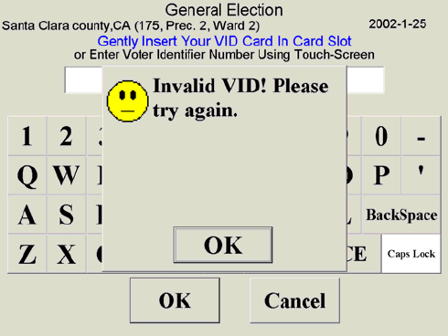
6.2.1 Miscellaneous Error Screens
The following are all of the error screens that the voter or poll worker may see.
Invalid VID#: This error message appears whenever the voter enters a wrong or invalid VID#
either manually or with invalid smart card.
Figure 6.1.3A
Avante International Technology, Inc.
Version 4.4.3 3
Wrong password: This error message appears whenever the poll worker enters a wrong
password.
Figure 6.1.3B:
6.2.2 Manufacturer’s Recommended Security Procedures
The following are some of the recommended security procedures for effective and secure voting
operation.
Power Supply: VOTE-TRAKKER™ is equipped with 1000VA battery power back-up supply
in the form of uninterruptable power supply (UPS). Please make sure the system is plugged into
a proper AC power source. The UPS and the VOTE-TRAKKER™ may be unplugged for
curbside voting if permitted. The same UPS should be plugged back after such operation.
Sealed System: It is recommended that VOTE-TRAKKER™ be sealed after the system is
loaded with the proper ballot and VID#. Such seal includes a mechanical lock and physical
tamper-obvious seal along the seam of the enclosure. It is recommended that the system
remained sealed before and during election to ensure data and system integrity. There is no other
data entry point other than the touch screen without proper entering of VID#.
Avante International Technology, Inc.
Version 4.4.3 4
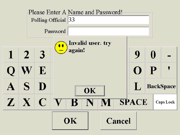
6.2.3 Machine Setting & Testing Functions
The following functions are found in the Machine Setting & Testing screen:
• Set Voting Machine – see section 4.1 for description
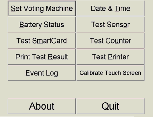
• Battery Status – shows the status of the power supply to the laptop (see Figure 6.2.3B).
• Test Smart Card – performs the same test of the smart card that is done during power up of the
voting machine (refer to section 4.1).
• Print Test Result – Prints the status report that is printed out during the power up of the voting
machine (refer to section 4.1).
• Date & Time – Sets the date and time of the laptop (see Figure 6.2.3C).
• Test Sensor – Tests the presence sensor (refer to section 4.1).
• Test Counter – Tests the counters (refer to section 4.1).
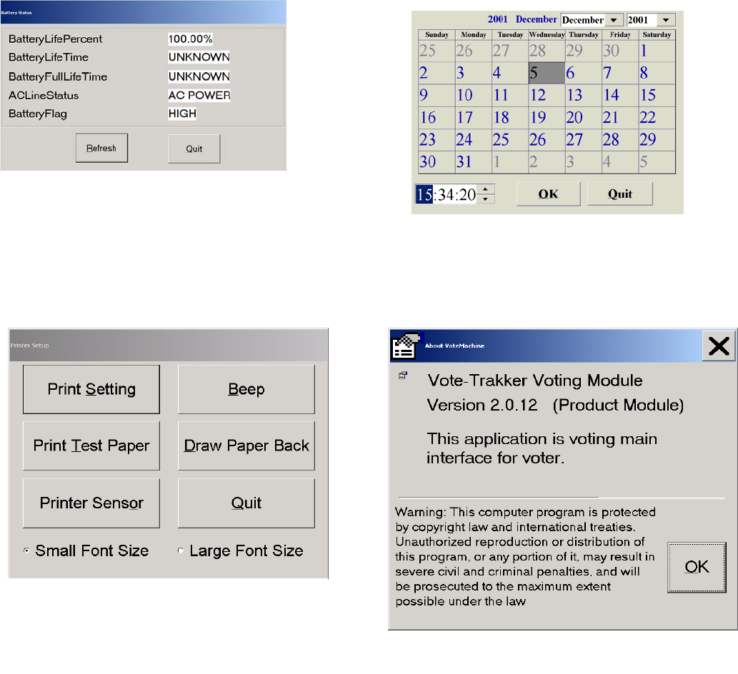
• Test Printer – Brings up a screen to perform various tests of the printer (see Figure 6.2.3D).
• Event Log – This function accesses the Event Log module via a login screen. Documentation is in
the Election Administrator’s Manual. Supervisor level personnel only access this module.
• Calibrate Touch Screen – Accesses the touch screen calibration program (see section 6.3)
• About – Shows the version number of the software that is installed on the voting machine (see
Figure 6.2.3E).
• Quit – Brings you back to the main election worker screen.
Figure 6.2.3A
Avante International Technology, Inc.
Version 4.4.3 5
In Figure 6.2.3D the font size relates to the receipt font only.
Figure 6.2.3B
Figure 6.2.3D
Figure 6.2.3E
Figure 6.2.3C
Avante International Technology, Inc.
Version 4.4.3 6
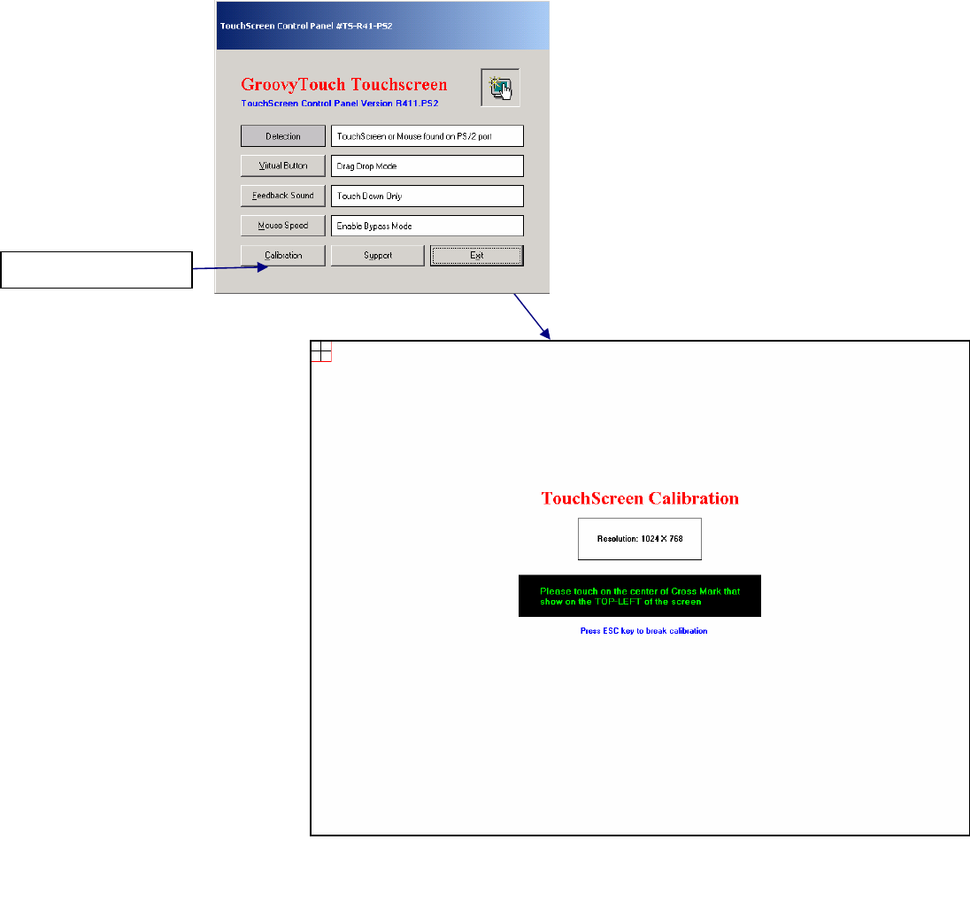
6.3 Calibration of Touch Screen
The touch screen has a built in calibration routine that is accessed during power up (see section
4.1) or from the Machine Settings and Test screen. There are several approved versions of the
touch screen software. The most common version employed is shown below. It takes four
touches to calibrate the touch screen. Follow the onscreen directions, if this procedure does not
work, then do not use the Vote-Trakker™ for voting and have it serviced immediately. Access
to the operating system is only limited to the highest-level administrator so onsite service other
than calibration is not available to the poll worker.
Select Calibration
Follow on screen
instructions
Figure 6.3A

Avante International Technology, Inc.
Version 4.4.3 7
If the “Virtual Button” is selected, the screen in Figure 6.3B is shown:
The correct setting is the “Touch Down Mode”. It is not recommended to use the other modes.
The “Feedback Sound” option is shown in Figure 6.3C:
The correct setting is “Touch Down Only”. It is not recommended to use the other modes.
Figure 6.3B
Figure 6.3C

Avante International Technology, Inc.
Version 4.4.3 8
The “Mouse Speed” settings are shown in Figure 6.3D:
The correct setting is to select the “Enable” checkbox in the “Bypass Mode” setting. It is not
recommended to change this setting.
Figure 6.3D
Avante International Technology, Inc.
Version 4.4.3 9
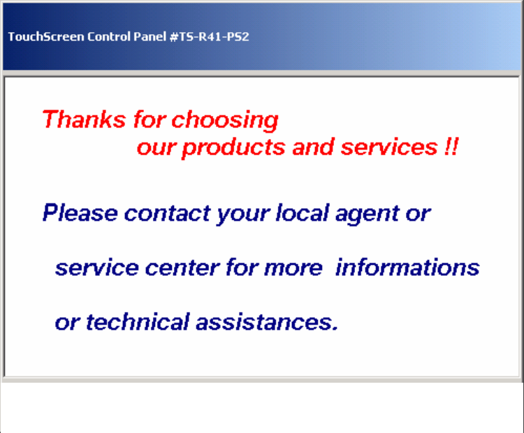
By selecting the “Support” button, a message, as shown in Figure 6.3E, appears:
Future versions of this touch screen software will allow for online support. However, if support
is needed, contact Avante International Technology, Inc. Do not attempt to contact the touch
screen manufacturer. They will not always be able to help because they do not know exactly
how the Vote-Trakker™ is configured.
Figure 6.3E

Avante International Technology, Inc.
Version 4.4.3 10
Printer User’s Guide for Vote-Trakker™
7. Printer Information
Avante International Technology, Inc.
Version 4.4.3 11
This section is derived directly from the manufacturer of the printer, Star Micronics. The contents are the
same as they appear in their manual. Sections that are not pertinent to users have been edited from this
guide to avoid confusion. If there is a problem not described in this guide, please contact your Avante
International Technology representative for further instruction.
NOTICE
• All rights reserved. Reproduction of any part of this manual in any form whatsoever, without STAR’s express
permission is forbidden.
• The contents of this manual are subject to change without notice.
• All efforts have been made to ensure the accuracy of the contents of this manual at the time of going to press.
However, should any errors be detected, STAR would greatly appreciate being informed of them.
• The above notwithstanding, STAR can assume no responsibility for any errors in this manual.
Copyright 1998 Star Micronics Co., LTD.
Avante International Technology, Inc.
Version 4.4.3 12
Table of Contents
1. GENERAL DESCRIPTION...................................................................................... 13
2. CONSTRUCTION...................................................................................................... 14
2.1 CONFIGURATION................................................................................................................... 14
2.2 PRINCIPLE OF OPERATION..................................................................................................... 14
3. GENERAL SPECIFICATIONS................................................................................ 16
4. PAPER ROLL SPECIFICATIONS.......................................................................... 17
5. DISPLAYS AND FUNCTIONS................................................................................. 19
5.1 LEDS.................................................................................................................................... 19
5.2 RESUME BUTTON ............................................................................................................... 19
5.3 POWER SWITCH AND BUTTON COMBINATIONS ..................................................................... 19
5.4 SENSOR ADJUSTING MODE ................................................................................................... 20
5.6 ERROR MESSAGES ................................................................................................................ 21
5.7 NEAR-END SENSOR POSITION............................................................................................... 23
6. CUTTER...................................................................................................................... 24
7. PRESENTER............................................................................................................... 25
8. RELIABILITY............................................................................................................ 26
8.1 DURING OPERATION.............................................................................................................. 26
8.2 DURING STORAGE ................................................................................................................. 26
8.3 LIFE TEST ............................................................................................................................. 27
9. INSTALLING THE PAPER ROLL ......................................................................... 28
10. MAINTENANCE...................................................................................................... 30
Avante International Technology, Inc.
Version 4.4.3 13
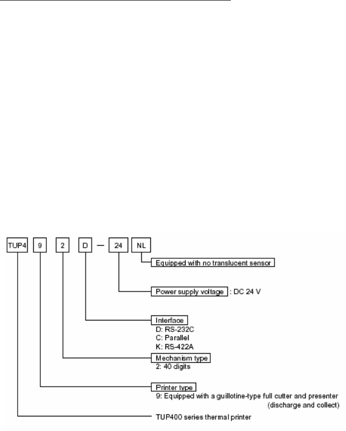
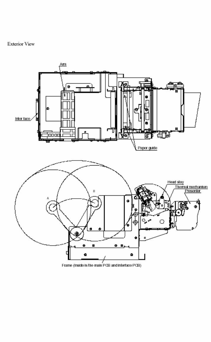
The TUP492-24 printer is a line thermal printer and is used in various electronic equipment, such as game
machines, ATMs and information kiosks. TUP492-24 is equipped with a presenter which discharge and
collect paper.
These printers feature the following:
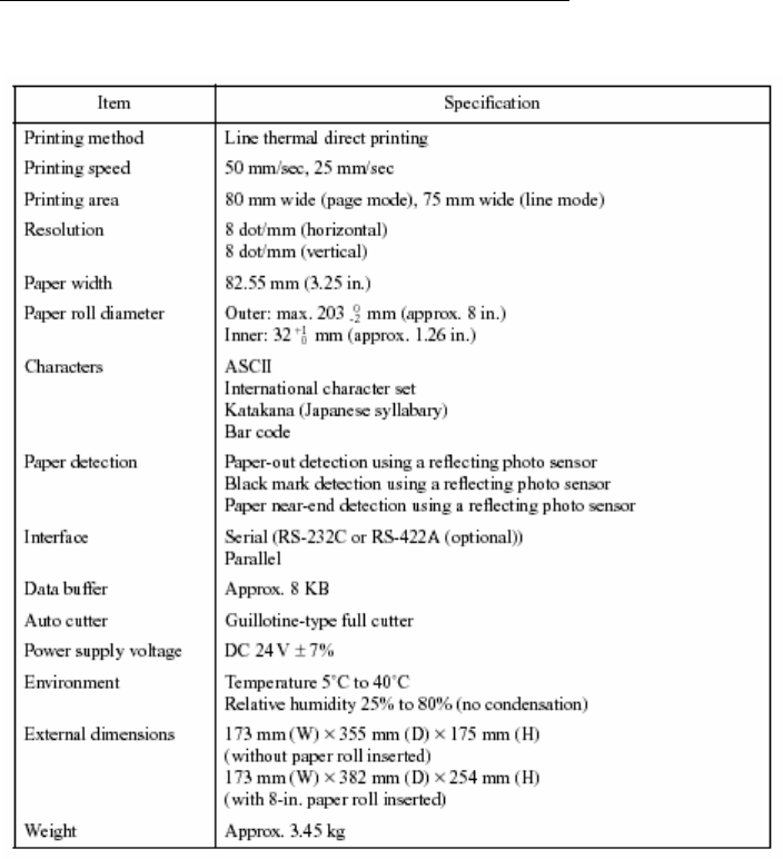
1. High-speed printing: 2 in./sec (50 mm/sec)
2. High resolution: 8 dots/mm vertically, 8 dots/mm horizontally (approx. 200 dpi)
3. Silent operation
4. Paper roll size: max. 8-inch diameter
5. Choice of three types of interfaces (optional)
6. Presenter function
Display of Model Name
1. GENERAL DESCRIPTION
Avante International Technology, Inc.
Version 4.4.3 14
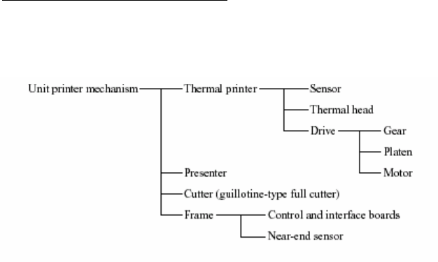
2.1 Configuration
The unit printer mechanism is constructed of the following components:
2.2 Principle of Operation
2.2.1 Drive and paper feed
The rotation of the stepping motor is transmitted to the gear, which turns the platen. The rotation of the
platen generates friction between it, the thermal paper and the thermal head, therefore causing the paper to
be fed.
2.2.2 Printer
Color appears on the thermal paper as the temperature of the thermal head’s heat-generating element
increases.
2.2.3 Presenter
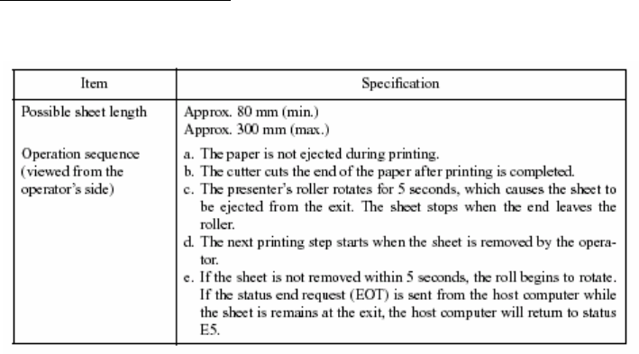
The edge of the thermal paper stops just before the presenter’s ejector, the continuous feed of the thermal
paper creates a loop and after printing is finished, the paper is cut. Then, the paper is fed out by the roller
in front of the ejector (The DC motor rotates the roller). Detecting the paper bottom end, the roller stops
its rotation.
When the fixed period of time passes, or the collection command is sent, the presenter collects the paper.
2. CONSTRUCTION
Avante International Technology, Inc.
Version 4.4.3 15
Avante International Technology, Inc.
Version 4.4.3 16
3. GENERAL SPECIFICATIONS
Avante International Technology, Inc.
Version 4.4.3 17
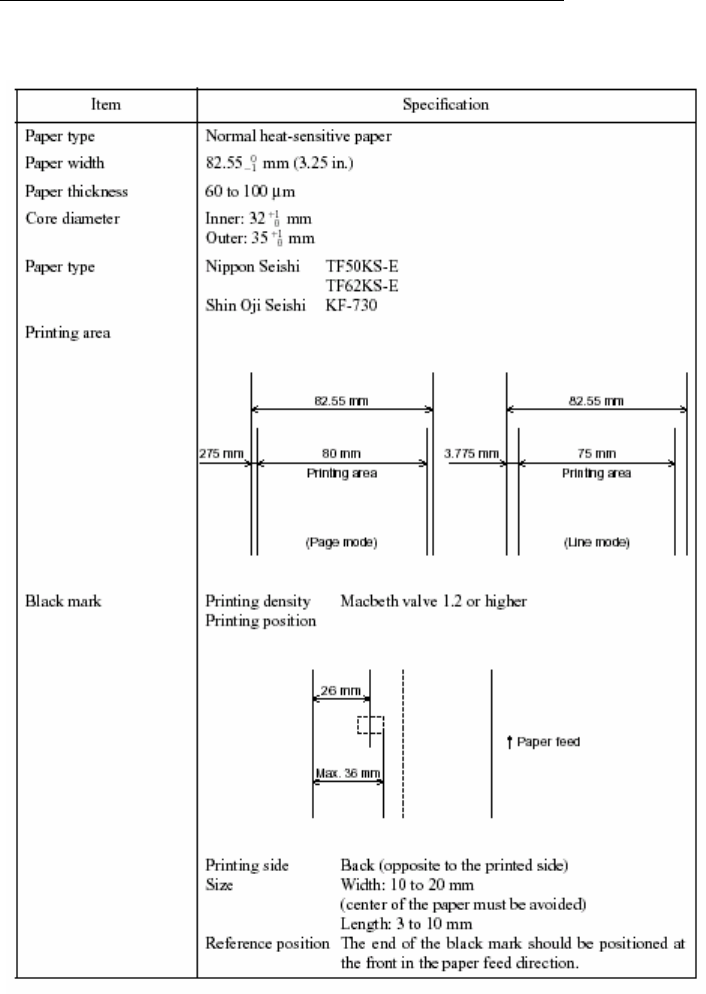
4. PAPER ROLL SPECIFICATIONS
Avante International Technology, Inc.
Version 4.4.3 18
Notes -
• Use paper that is rolled inward.
• Do not affix the end of the paper to the paper roller.
• Paper jams may occur depending on the paper quality used and the pattern printed.
• If the machine is turned off and left for a long time with paper caught in the thermal head, the paper should be
removed and inserted again.
• Keep this machine on a level surface.
• The roller may leave short marks in the end of the paper.
Avante International Technology, Inc.
Version 4.4.3 19
The LEDs and RESUME button are mounted on the NEPCB.
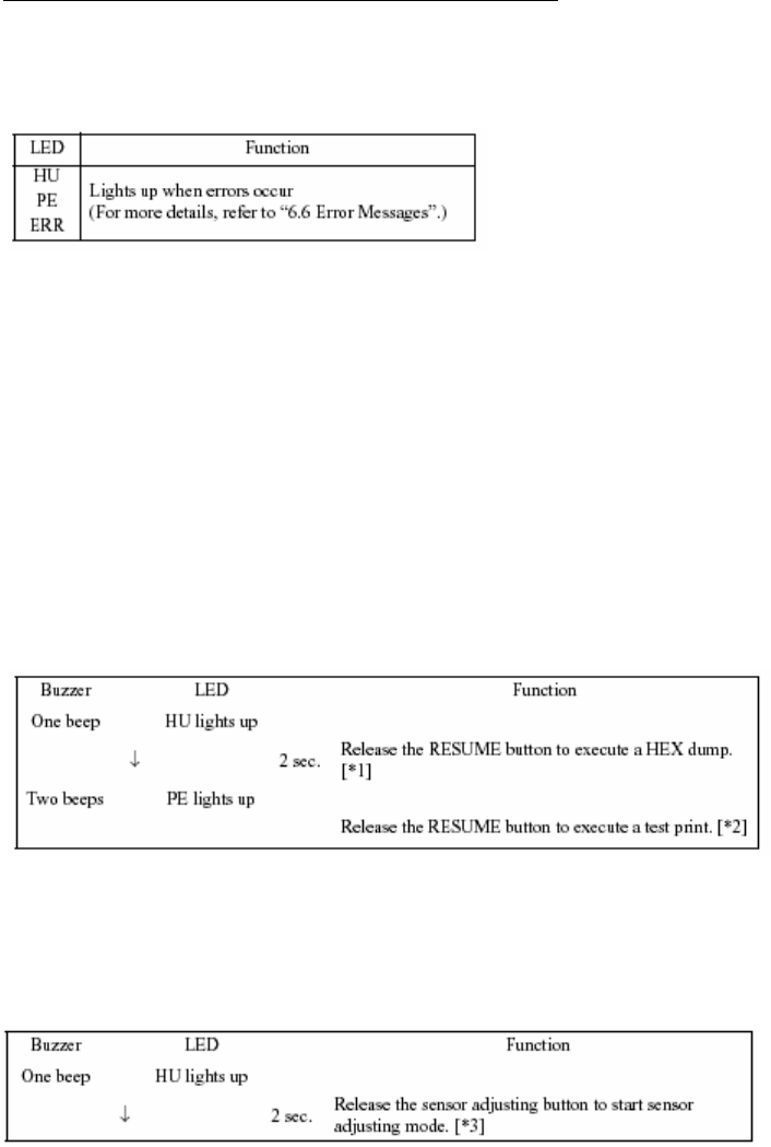
5.1 LEDs
5.2 RESUME Button
When no paper is inserted, insert more paper, and then press this button to automatically feed the
specified length of paper (approx. 80 mm when the presenter is installed or approx. 30 mm when it is
not). After the paper is cut, the printer will go back on line.
5.3 Power Switch and Button Combinations
The following settings can be made by pressing either the RESUME button or the sensor adjusting button
at the same time that the power switch is turned on.
<RESUME button and power switch>
[*1] The HEX dump mode remains valid until the power is turned off.
[*2] The printer continues the test print until the power is turned off.
<Sensor adjusting button and power switch>
[*3] Do not continue pressing the sensor adjusting button for more than two seconds.
Note- The Line and Page modes cannot be chosen with the panel buttons; these modes can only be chosen
with commands.
5. DISPLAYS AND FUNCTIONS
Avante International Technology, Inc.
Version 4.4.3 20
5.4 Sensor Adjusting Mode
a) Reflecting sensor (black mark sensor)
• Insert the paper in front of the sensor mechanism so that a black mark is not positioned in front of the sensor.
• Adjust the reflecting sensor controller VR4 on the PCB until the HU LED lights up.
b) Paper-out sensor
• Insert the paper in front of the sensor mechanism so that a black mark is not positioned in front of the sensor.
• Adjust the paper-out sensor controller VR3 on the PCB until the PE LED lights up.
Avante International Technology, Inc.
Version 4.4.3 21
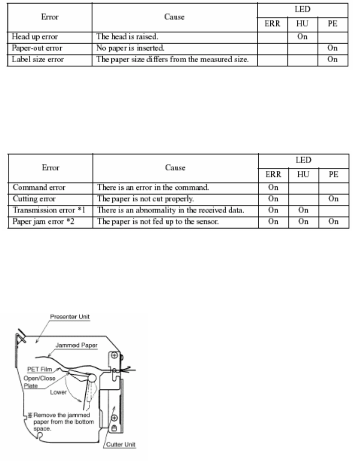
5.6 Error Messages
It is possible to determine the type of error occurring by observing the printing results and which LED
lights up.
a) Recoverable errors
• The printer goes off line when these errors occur.
• To resume operation, remove the cause of the error, then press the RESUME button.
b) Unrecoverable errors
• The printer goes off line when these errors occur.
• Operation of the printer will be resumed by pressing the resume button after the cause of the unrecoverable
error is removed.
*1 Valid only with the serial interface
*2 If the paper is jammed inside the presenter
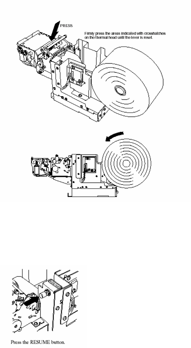
Paper Jam, Case 1: Removing paper from inside the presenter.
(Procedure)
1) If there is a paper jam at the Open/Close plate, lower the Open/Close plate if
it is in the up position. (If it is in the down position, leave it down.)
2) Remove the jammed paper from the space below the presenter unit.
Note - When lowering the Open/Close plate, be careful not to bend the PET film
unit.
Avante International Technology, Inc.
Version 4.4.3 22
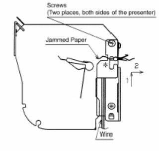
Paper Jam, Case 2: Removing paper from near the cutter.
(Procedure)
1) When paper is jammed inside the cutter, if it cannot be removed by the
procedure in Case 1, take out the screws on both sides of the presenter, as
shown in the figure.
2) Slide the presenter along the * part in the figure, separating the presenter
and the cutter, then remove the jammed paper.
3) After removing the jammed paper, slide the presenter back, following
the procedure in 2) in reverse order, then fasten it in its original position
using the screws.
Note- When fitting the presenter with the cutter in 3) above, be careful not to get the two wires shown in
the figure caught between the presenter and cutter.
c) Other errors
• Data errors (<ESC> “PC” command: defines character and bar code data) A data error will occur if an invalid
character or bar code type is selected or if the print result extends outside the print area. When a data error
occurs, all commands become invalid (character strings and bar codes are not printed). However, the printer
will not go off line and the LEDs will not light up.
Avante International Technology, Inc.
Version 4.4.3 23
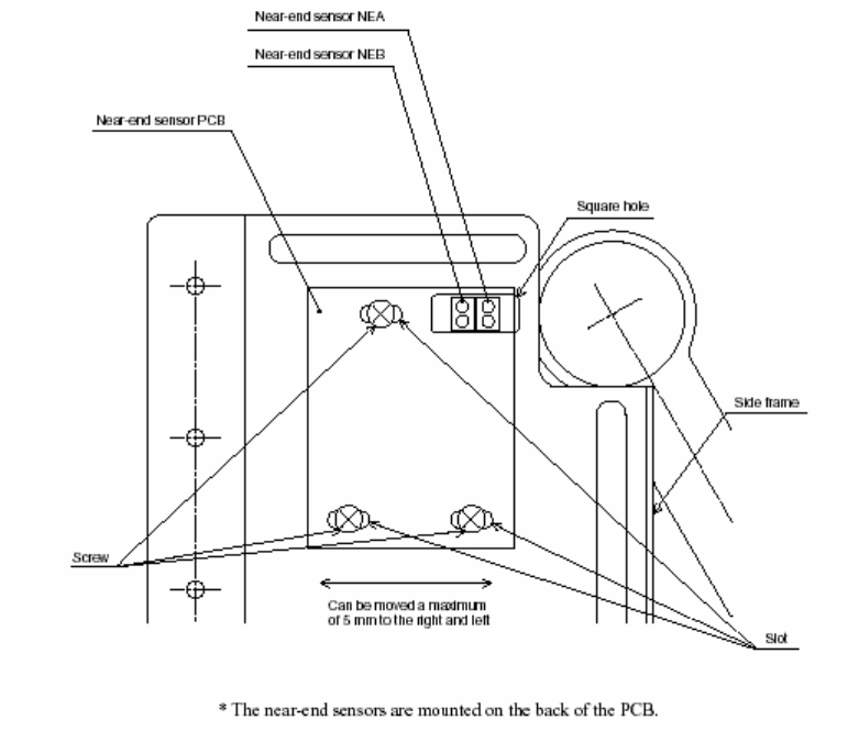
5.7 Near-End Sensor Position
<Technical Specifications>
The near-end sensors can be moved a maximum of 5 mm to the right or left by moving the near-end
sensor PCB.
Slightly loosen the three screws (without removing them) used to install the PCB, then move the PCB to
the desired position. After making sure that the PCB fits properly (i.e. it is not loose), tighten the three
screws. (Do not break the PCB.)
Avante International Technology, Inc.
Version 4.4.3 24
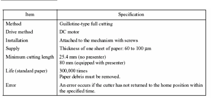
Notes- If the cutter is not located at the home position when an error has occurred, it can be returned to
the home position by removing the cause of the error and turning the power off, then on again.
The cutter can also be returned to the home position by turning off the power, inserting a
screwdriver into the hole on the side of the cutter, then rotating the motor until the cutter is
returned to the position which is believed to be the home position.
6. CUTTER
Avante International Technology, Inc.
Version 4.4.3 25
7. PRESENTER
Avante International Technology, Inc.
Version 4.4.3 26
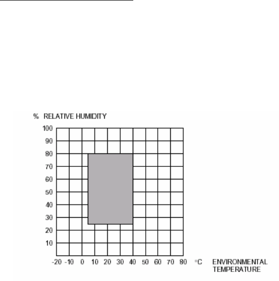
8.1 During operation
Temperature: 5° ~ 40°C
Humidity: 25% RH ~ 80% RH (no condensation)
Operating temperature and humidity ranges
Notes- When the environmental temperature is too high, the thermal head temperature sensor is activated
and the printer stops operating.
8.2 During storage
Temperature: –20°C ~ 60°C
Humidity: 10% RH ~ 90% RH (no condensation)
8. RELIABILITY
Avante International Technology, Inc.
Version 4.4.3 27
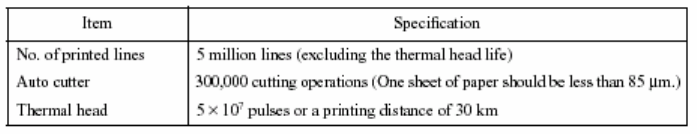
8.3 Life Test
MCBF
Notes-
• The thermal head life given above is applicable for cases when standard paper is used.
• Printing continuously at a print ratio of less than 12.5% increases the resistance of the thermal head’s heat-
generating element by more than 15% of the initial value.
• Excluding damages caused by dust, foreign objects etc.
• Missing dot ratio maximum of 0.5% over 50 km.
Avante International Technology, Inc.
Version 4.4.3 28
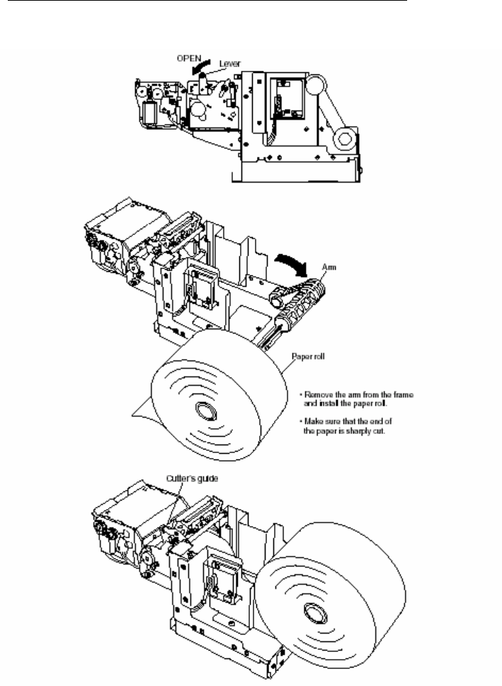
Pass the paper over the damper shaft, pass it under the thermal head, then insert the paper between cutter
guides. Double check that the paper is inserted into the cutter by looking into the small wholes on the
upper cutter guide. Feed the paper until the end enters the presenter’s roller.
9. INSTALLING THE PAPER ROLL
Avante International Technology, Inc.
Version 4.4.3 29
Carefully place the paper roll on the frame, then wind the roll to remove any slack in the paper.
(Incorrectly installing the paper roll may bend the frame or cause a paper jam.)

Avante International Technology, Inc.
Version 4.4.3 30
Regular maintenance is very important since minute debris of thermosensible paper sticking to the platen
may cause slipping of the paper feeder. Maintenance should be made as follows:
Maintenance Timing:
Generally, TUP series should be maintained every time after using 8 rolls of 8 inch ø Star Standard Spec
paper roll, or 6 month.
Maintenance Procedures:
1. Make sure that the power supply is turned off before starting the maintenance procedures.
2. Wipe and rub the platen gently with a dry soft cloth to remove all debris stuck on the platen
surface. (Turn the platen around to remove debris from all the surface.)
• Take enough care not to touch the gears and the cutter guide when wiping the platen to avoid any bodily
injury.
• Avoid wiping a same spot of the platen continuously, otherwise it may cause deformation of the platen.
• Wash your hands thoroughly before touching the platen.
10. MAINTENANCE
Avante International Technology, Inc.
Version 4.4.3 31
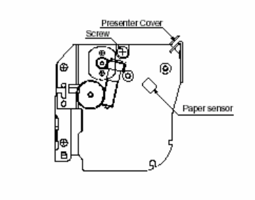
3. Remove the dirt from the thermal head using a cotton bud or soft cloth dipped in alcohol.
4. Remove all dirt, dust or paper debris, etc. adhering to the sensors (particularly the reflector type
sensors) of the thermal mechanism and the presenter.
Note- For the presenter’s paper sensor, take out the screws in the presenter cover on the side as shown in the
figure below, remove the cover, then remove the dust from above. Also, after maintenance, return the
presenter cover to its original position and fasten it with the screws which were taken out before.