Avaya AP8120 802.11abgn Access Point User Manual AP 8120 Regulatory Doc NN47251 104 01 02 REGAP
Avaya, Inc. 802.11abgn Access Point AP 8120 Regulatory Doc NN47251 104 01 02 REGAP
Avaya >
Contents
- 1. User Manual
- 2. AP 8120_Installation_NN47251-302_01_AD_IAP
- 3. AP 8120_Regulatory_Doc_NN47251-104_01 02_REGAP
- 4. NN47251-104 02.02 REGAP8120
- 5. NN47251-109 01.02 REGAP8120E
AP 8120_Regulatory_Doc_NN47251-104_01 02_REGAP

Avaya WLAN 8100
Regulatory Information - AP 8120
Release: 1.0
Document Revision: 01.02
NN47251-104 325887-A
.
Avaya WLAN 8100
Release: 1.0
Publication: NN47251-104
Document release date: 18 May 2010
© 2010 Avaya Inc.
All Rights Reserved.
Notice
While reasonable efforts have been made to ensure that the information in this document is complete and accurate
at the time of printing, Avaya assumes no liability for any errors. Avaya reserves the right to make changes and
corrections to the information in this document without the obligation to notify any person or organization of such
changes.
Documentation disclaimer
Avaya shall not be responsible for any modifications, additions, or deletions to the original published version of
this documentation unless such modifications, additions, or deletions were performed by Avaya. End User agree
to indemnify and hold harmless Avaya, Avaya’s agents, servants and employees against all claims, lawsuits,
demands and judgments arising out of, or in connection with, subsequent modifications, additions or deletions to
this documentation, to the extent made by End User.
Link disclaimer
Avaya is not responsible for the contents or reliability of any linked Web sites referenced within this site or
documentation(s) provided by Avaya. Avaya is not responsible for the accuracy of any information, statement or
content provided on these sites and does not necessarily endorse the products, services, or information described
or offered within them. Avaya does not guarantee that these links will work all the time and has no control over the
availability of the linked pages.
Warranty
Avaya provides a limited warranty on this product. Refer to your sales agreement to establish the terms of the
limited warranty. In addition, Avaya’s standard warranty language, as well as information regarding support for this
product, while under warranty, is available to Avaya customers and other parties through the Avaya Support Web
site: http://www.avaya.com/support
Please note that if you acquired the product from an authorized reseller, the warranty is provided to you by said
reseller and not by Avaya.
Licenses
THE SOFTWARE LICENSE TERMS AVAILABLE ON THE AVAYA WEBSITE, HTTP://SUPPORT.AVAYA.CO
M/LICENSEINFO/ ARE APPLICABLE TO ANYONE WHO DOWNLOADS, USES AND/OR INSTALLS AVAYA
SOFTWARE, PURCHASED FROM AVAYA INC., ANY AVAYA AFFILIATE, OR AN AUTHORIZED AVAYA
RESELLER (AS APPLICABLE) UNDER A COMMERCIAL AGREEMENT WITH AVAYA OR AN AUTHORIZED
AVAYA RESELLER. UNLESS OTHERWISE AGREED TO BY AVAYA IN WRITING, AVAYA DOES NOT EXTEND
THIS LICENSE IF THE SOFTWARE WAS OBTAINED FROM ANYONE OTHER THAN AVAYA, AN AVAYA
AFFILIATE OR AN AVAYA AUTHORIZED RESELLER, AND AVAYA RESERVES THE RIGHT TO TAKE LEGAL
ACTION AGAINST YOU AND ANYONE ELSE USING OR SELLING THE SOFTWARE WITHOUT A LICENSE. BY
INSTALLING, DOWNLOADING OR USING THE SOFTWARE, OR AUTHORIZING OTHERS TO DO SO, YOU, ON
BEHALF OF YOURSELF AND THE ENTITY FOR WHOM YOU ARE INSTALLING, DOWNLOADING OR USING
THE SOFTWARE (HEREINAFTER REFERRED TO INTERCHANGEABLY AS “YOU” AND “END USER”), AGREE
TO THESE TERMS AND CONDITIONS AND CREATE A BINDING CONTRACT BETWEEN YOU AND AVAYA
INC. OR THE APPLICABLE AVAYA AFFILIATE (“AVAYA”).
Copyright
Except where expressly stated otherwise, no use should be made of the Documentation(s) and Product(s) provided
by Avaya. All content in this documentation(s) and the product(s) provided by Avaya including the selection,
arrangement and design of the content is owned either by Avaya or its licensors and is protected by copyright and
other intellectual property laws including the sui generis rights relating to the protection of databases. You may not
modify, copy, reproduce, republish, upload, post, transmit or distribute in any way any content, in whole or in part,
including any code and software. Unauthorized reproduction, transmission, dissemination, storage, and or use
without the express written consent of Avaya can be a criminal, as well as a civil offense under the applicable law.
Third Party Components
Certain software programs or portions thereof included in the Product may contain software distributed under
third party agreements ("Third Party Components"), which may contain terms that expand or limit rights to use
certain portions of the Product ("Third Party Terms"). Information regarding distributed Linux OS source code (for
those Products that have distributed the Linux OS source code), and identifying the copyright holders of the Third
Party Components and the Third Party Terms that apply to them is available on the Avaya Support Web site:
http://support.avaya.com/Copyright
Trademarks
.
The trademarks, logos and service marks (“Marks”) displayed in this site, the documentation(s) and product(s) provided by Avaya
are the registered or unregistered Marks of Avaya, its affiliates, or other third parties. Users are not permitted to use such
Marks without prior written consent from Avaya or such third party which may own the Mark. Nothing contained in this site,
the documentation(s) and product(s) should be construed as granting, by implication, estoppel, or otherwise, any license or
right in and to the Marks without the express written permission of Avaya or the applicable third party. Avaya is a registered
trademark of Avaya Inc. All non-Avaya trademarks are the property of their respective owners.
Downloading documents
For the most current versions of documentation, see the Avaya Support. Web site: http://www.avaya.com/support
Contact Avaya Support
Avaya provides a telephone number for you to use to report problems or to ask questions about your product. The
support telephone number is 1-800-242-2121 in the United States. For additional support telephone numbers, see
the Avaya Web site: http://www.avaya.com/support
.
.

5
.
Contents
Regulatory Compliance Statements 7
Federal Communications Commission (FCC) Compliance Notices 7
Class B Interference Statement 7
FCC Caution: 8
RF Radiation Exposure and Hazard Statement 8
Non-Modification Statement 8
Deployment Statement 8
Dynamic Frequency Selection (DFS) in the 5.0 GHz UNII bands 8
Canadian IC Statements 9
European Union and European Free Trade Association (EFTA) Regulatory
Compliance 9
Declaration of Conformity 10
European Community Declaration of Conformity 11
Countries of Operation and Restrictions of Use in the European Community 13
Operation Using the 2.400 to 2.4835 GHz Channels in the European
Community 13
Operation Using the 5.15 to 5.25 GHz, 5.25 to 5.35 GHz, and 5.470 to 5.725
GHz Channels in the European Community 13
Dynamic Frequency Selection (DFS) 14
Transmit Power Control 14
Antenna Statement 15
English 17
Cable requirements 17
Mounting a wireless LAN access point on a wall 17
Installing an Access Point with a ceiling grid adaptor 19
Safety Messages 22
Deutsch 23
Kabelanschlüsse 23
Wandmontage eines Wireless LAN Access Points 23
Deckenmontage eines Access Points (Rasterdecke) 25
Sicherheitshinweise 28
Español 31
Requisitos del cable 31
Avaya WLAN 8100
Regulatory Information - AP 8120
NN47251-104 01.02 18 May 2010
.

6
Montaje en la pared de un punto de acceso inalámbrico para redes LAN 31
Instalación de un punto de acceso con un adaptador para estructuras de techos
desmontables 34
Advertencias de seguridad 36
Français 39
Configuration requise pour les câbles 39
Montage mural du point accès WLAN 39
Installation du point accès avec un adaptateur pour grille de plafond 41
Messages de sécurité 44
Português do Brasil 47
Requisitos de cabo 47
Instalando um ponto de acesso LAN sem fio em uma parede 47
Instalando um ponto de acesso com um adaptador de grade de teto 49
Mensagens de segurança 52
Avaya WLAN 8100
Regulatory Information - AP 8120
NN47251-104 01.02 18 May 2010
.

7
.
Regulatory Compliance Statements
The Avaya WLAN 8100 product line consists of the following models:
•AP 8120-R00
•AP 8120-R06
This section contains regulatory compliance statements for these units.
Federal Communications Commission (FCC) Compliance Notices
This section includes the following FCC statements for the AP 8120-R00
access point:
•FCC ID:
•Class B Interference Statement
•RF Radiation Exposure and Hazard Warning
•Non-Modification Statement
•Deployment Statement
Class B Interference Statement
This equipment has been tested and found to comply with the limits for
a Class B digital device, pursuant to Part 15 of the FCC Rules. These
limits are designed to provide reasonable protection against harmful
interference in a residential installation. This equipment generates, uses,
and can radiate radio frequency energy and, if not installed and used in
accordance with the instructions, may cause harmful interference to radio
communications. However, there is no guarantee that interference will
not occur in a particular installation. If this equipment does cause harmful
interference to radio or television reception, which can be determined by
turning the equipment off and on, the user is encouraged to try to correct
the interference by one or more of the following measures:
•Reorient or relocate the receiving antenna.
•Increase the separation between the equipment and receiver.
Avaya WLAN 8100
Regulatory Information - AP 8120
NN47251-104 01.02 18 May 2010
.

8Regulatory Compliance Statements
•Connect the equipment into an outlet on a circuit different from that to
which the receiver is connected.
•Consult the dealer or an experienced radio/TV technician for help.
FCC Caution:
This device complies with Part 15 of the FCC Rules. Operation is subject
to the following two conditions: (1) This device may not cause harmful
interference, and (2) this device must accept any interference received,
including interference that may cause undesired operation.
RF Radiation Exposure and Hazard Statement
To ensure compliance with FCC RF exposure requirements, this device
must be installed in a location such that the antenna of the device will
be greater than 20 cm (8 in.) away from all persons. Using higher gain
antennas and types of antennas not covered under the FCC certification
of this product is not allowed. Installers of the radio and end users of the
product must adhere to the installation instructions provided in this manual.
This transmitter must not be co-located or operating in conjunction with
any other antenna or transmitter.
Non-Modification Statement
Use only the supplied internal antenna. Unauthorized antennas,
modifications, or attachments could damage the AP 8120-R00 and violate
FCC regulations. Any changes or modifications not expressly approved
by the party responsible for compliance could void the user’s authority to
operate this equipment.
Deployment Statement
This product is certified for indoor deployment only. Do not install or use
this product outdoors.
Dynamic Frequency Selection (DFS) in the 5.0 GHz UNII bands
The AP 8120-R00 access point has been prohibited, via software, from
operating in the 5250 to 5350 MHz and 5470 to 5725 MHz frequency
bands for the US and Canada because it cannot meet the DFS
requirements as outlined in the rules of the FCC for Part 15, Subpart E
that come into force on July 20, 2007.
Avaya WLAN 8100
Regulatory Information - AP 8120
NN47251-104 01.02 18 May 2010
.

European Union and European Free Trade Association (EFTA) Regulatory Compliance 9
Canadian IC Statements
IC: (Applies to AP 8120-R00)
Operation is subject to the following two conditions in Canada:
1. This device may not cause interference, and
2. This device must accept any interference, including interference that
may cause undesired operation of the device.
To prevent radio interference to the licensed service (i.e. co-channel
Mobile Satellite systems) this device is intended to be operated indoors
and away from windows to provide maximum shielding. Equipment (or its
transmit antenna) that is installed outdoors is subject to licensing and not
supported by the AP 8120-R00 access point.
Because high power radars are allocated as primary users (meaning they
have priority) in the 5250 to 5350 MHz band, these radars could cause
interference and/or damage to license exempt WLAN devices.
European Union and European Free Trade Association (EFTA)
Regulatory Compliance
This equipment may be operated in the countries that comprise the
member countries of the European Union and the European Free Trade
Association. These countries, listed in the following paragraph, are
referred to as The European Community throughout this document:
AUSTRIA, BELGIUM, BULGARIA, CYPRUS, CZECH REPUBLIC,
DENMARK, ESTONIA, FINLAND, FRANCE, GERMANY, GREECE,
HUNGARY, IRELAND, ITALY, LATVIA, LITHUANIA, LUXEMBOURG,
MALTA, NETHERLANDS, POLAND, PORTUGAL, ROMANIA, SLOVAKIA,
SLOVENIA, SPAIN, SWEDEN, UNITED KINGDOM, ICELAND,
LICHTENSTEIN, NORWAY, SWITZERLAND.
The Avaya WLAN 8100 AP 8120-R06 access point communicates with an
Avaya WLAN 8100 Wireless Controller using a standard CAT-5 (Category
5) or higher 1000 Mbps twisted pair Ethernet cable to provide wireless
local area networking (WLAN) capabilities. The Avaya WLAN 8100 AP
8120-R06 access point includes two 802.11a+n, b/g+n radios and one, six
element, dual-band antenna omnidirectional internal antenna.
Avaya WLAN 8100
Regulatory Information - AP 8120
NN47251-104 01.02 18 May 2010
.

10 Regulatory Compliance Statements
Declaration of Conformity
Marking by this symbol
indicates compliance with the Essential Requirements of the R&TTE
Directive of the European Union (1999/5/EC). This equipment meets the
following conformance standards:
Safety: EN 60950-1:2001 + A11:2004
EMC: EN 55022:2006, EN 55024:1998 + A1:2001 + A2:2003, EN
301-489-1 v1.6.1, EN 301-489-17 v1.2.1, CISPR22:2005, CISPR24
Including: EN 61000-3-2, -3-3, -4-2, -4-3, -4-4, -4-5, -4-6 and -4-11.
The product is also licensed as required for additional country specific
standards as required for the International Marketplace.
Radio: EN 300-328 v.1.7.1 (2006-10) & EN 301-893 v.1.5.1 (2008-12)
DEVIATION: The AP 8120-R00 access point was tested to and are
compliant with all of the technical specifications of EN 301-893 v1.5.1 for
operation in the 5.0 GHz bands, except the DFS requirements in the 5600
– 5650 MHz band.
IEEE 802.11a operation in the 5250 to 5350 MHz and 5470 to 5725
MHz frequency bands is governed by ETSI EN 301-893 v1.5.1 and the
R&TTE Directive 1999/5/EC. Effective July 1, 2008, EN 301-893 v1.5.1
was updated to require compliance with 0.8 µsecond pulse widths and
staggered PRF’s in the 5470 – 5725 MHz band. The AP 8120-R00 access
point meets compliance with these new mandates by disabling operation,
via software, on channels 120, 124, 128 and 132 in the 5600 to 5650 MHz
frequency band because it cannot meet the 0.8 µsecond pulse width and
staggered PRF DFS requirements as outlined in the updated EN 301-893
v1.5.1 standard.
Electromagnetic compatibility and Radio spectrum Matters (ERM);
Wideband transmission systems; Data transmission equipment operating
in the 2,4 GHz ISM band and using wide band modulation techniques and
Broadband Radio Access Networks (BRAN); 5 GHz high performance
RLAN. Certifications are harmonized to the EN standards covering
essential requirements under article 3.2 of the R&TTE Directive.
SAR: EN 50385:2002
Avaya WLAN 8100
Regulatory Information - AP 8120
NN47251-104 01.02 18 May 2010
.

European Union and European Free Trade Association (EFTA) Regulatory Compliance 11
European Community Declaration of Conformity
WLAN Radio Model AP 8120-R06, as stated in the following Declarations
of Conformity, represents all models in the AP 8120-R06 as listed above.
Bulgaria
, avayal , WLAN AP 8120-R06, 1999/5
Czech
Republic Èesky
Avaya tímto prohlaˇ
suje, že tento WLAN Rádio Model AP 8120-R06, je ve shodì se
základními požadavky a dalˇ
sími pøísluˇ
snými ustanoveními smìrnice 1999/5/ES.
Denmark Dansk
Undertegnede Avayaerklærer herved, at følgende udstyr WLAN Radio Model
AP 8120-R06, overholder de væsentlige krav og øvrige relevante krav i direktiv
1999/5/EF.
English English
Hereby, Avaya declares that this WLAN Radio Model AP 8120-R06, is in
compliance with the essential requirements and other relevant provisions of
Directive 1999/5/EC.
Estonia Eesti
Käesolevaga kinnitab Avayaseadme WLAN Radio Model AP 8120-R06, vastavust
direktiivi 1999/5/EÜ põhinõuetele ja nimetatud direktiivist tulenevatele teistele
asjakohastele sätetele.
Finland Suomi
Avayavakuuttaa täten että WLAN Radio Esikuvallinen AP 8120-R06, tyyppinen laite
on direktiivin 1999/5/EY oleellisten vaatimusten ja sitä koskevien direktiivin muiden
ehtojen mukainen.
France Français
Par la présente Avaya déclare que l’appareil Model Par radio AP 8120-R06
de WLAN, est conforme aux exigencies essentielles et aux autres dispositions
pertinentes de la directive 1999/5/CE.
Germany Deutsch
Hiermit erklärt Avaya., dass sich das Gerät WLAN Radiomodell AP 8120-R06,
in Übereinstimmung mit den grundlegenden Anforderungen und den übrigen
einschlägigen Bestimmungen der Richtlinie 1999/5/EG befindet.
Greece
Hungary Magyar
Alulírott, Avayanyilatkozom, hogy a WLAN Rádió Minta AP 8120-R06, megfelel
a vonatkozó alapvetõ követelményeknek és az 1999/5/EC irányelv egyéb
elõírásainak.
Avaya WLAN 8100
Regulatory Information - AP 8120
NN47251-104 01.02 18 May 2010
.

12 Regulatory Compliance Statements
Italy Italiano
Con la presente Avayadichiara che questo Modello Radiofonico AP 8120-R06 di
WLAN, è conforme ai requisiti essenziali ed alle alter disposizioni pertinenti stabilite
dalla direttiva 1999/5/CE.
Latvia Latviski
Ar ˇ
so Avayadeklarç, ka WLAN Radio Model AP 8120-R06, atbilst Direktîvas
1999/5/EK bûtiskajâm prasîbâm un citiem ar to saistîtajiem noteikumiem.
Lithuania Lietuviø
ˇ
Siuo Avayadeklaruoja, kad ˇ
sis WLAN Radio Model AP 8120-R06, atitinka esminius
reikalavimus ir kitas 1999/5/EB Direktyvos nuostatas.
Malta Malti
Hawnhekk, Avaya., jiddikjara li dan WLAN Radio Model AP 8120-R06, jikkonforma
mal-tiijiet essenzjali u ma provvedimenti orajn relevanti li hemm fid-Dirrettiva
1999/5/EC.
Netherlands Netherlands
Hierbij verklaart Avayadat het toestel WLAN Radiomodel AP 8120-R06, in
overeenstemming is met de essentiële eisen en de andere relevante bepalingen
van richtlijn 1999/5/EG.
Poland Polski
Niniejszym Avayaooewiadcza, ¿e WLAN Radio Model AP 8120-R06, jest zgodny z
zasadniczymi wymogami oraz pozosta³ymi stosownymi postanowieniami Dyrektywy
1999/5/EC.
Portugal Português
Avaya declara que este Modelo De rádio AP 8120-R06 de WLAN, está conforme
com os requisitos essenciais e outras disposições da Directiva 1999/5/CE.
Romania Român
Astfel, Avaya declarã acel acest WLAN Radio Model AP 8120-R06, este în
conformitate cu cerinþele necesare ºi proviziile alte semnificative de Directive 1999
5 EC.
Slovakia Slovensky
Avaya týmto vyhlasuje, že WLAN Radio Model AP 8120-R06 spåòa základné
požiadavky a vˇ
setky prísluˇ
sné ustanovenia Smernice 1999/5/ES.
Slovenia Slovensko
Avaya izjavlja, da je ta WLAN Radio Model AP 8120-R06, v skladu z bistvenimi
zahtevami in ostalimi relevantnimi doloèili directive 1999/5/ES.
Avaya WLAN 8100
Regulatory Information - AP 8120
NN47251-104 01.02 18 May 2010
.

Countries of Operation and Restrictions of Use in the European Community 13
Spain Español
Por medio de la presente Avaya declara que el Modelo De radio AP 8120-R06 de
WLAN, cumple con los requisitos esenciales y cualesquiera otras disposiciones
aplicables o exigibles de la Directiva 1999/5/CE.
Sweden Svenska
Härmed intygar Avaya elatt denna WLAN Radiotelegrafera till Modell AP 8120-R06,
står I överensstämmelse med de väsentliga egenskapskrav och övriga relevanta
bestämmelser som framgår av direktiv 1999/5/EG.
Countries of Operation and Restrictions of Use in the European
Community
Operation Using the 2.400 to 2.4835 GHz Channels in the European
Community
The professional installer should use the configuration utility provided
with this product to verify the current channel of operation, the expected
transmit power level, and to confirm that the device is operating in
conformance with the spectrum usage rules for the selected European
Community country. If operation is occurring outside of the allowable
channels as indicated in this guide, then operation of the product
must cease immediately and the installer must consult with the local
technical support staff responsible for the wireless network.
This device is intended to be operated in all countries of the European
Community. Additional restrictions of use for the AP 8120-R00 access
point within the European Community countries in the 2.400 to 2.4835 GHz
band are listed below.
•The frequencies associated with channels 1 to 13 in the 2.400 to
2.4835 GHz band are allowed to be used either indoors or outdoors in
all countries of the European Community, except where noted below.
•In France, the following operation is permitted:
— Indoor operation is permitted in the 2.400 to 2.4835 GHz band on
channels 1 to 13 at a maximum EIRP of 100 mW (20 dBm).
The AP 8120-R06 access point, using the internal antennas, are
guaranteed to meet this limit by automatically adjusting the transmit power
level through the operating software.
Operation Using the 5.15 to 5.25 GHz, 5.25 to 5.35 GHz, and 5.470 to
5.725 GHz Channels in the European Community
To remain in conformance with European National spectrum usage
laws, follow the channel limitations associated with the 5 GHz bands as
specified in this document. The professional installer should verify the
current channel of operation and the expected transmit power level of
Avaya WLAN 8100
Regulatory Information - AP 8120
NN47251-104 01.02 18 May 2010
.

14 Regulatory Compliance Statements
the AP 8120-R00 access point to confirm that the device is operating in
conformance with the spectrum usage rules for the European Community
country where the unit is being installed. If operation is occurring
outside of the allowable frequencies or above the power levels, as
indicated in this guide, then operation of the product must cease
immediately and the installer must consult with the local technical support
staff responsible for the wireless network.
This device is intended to be operated in all countries of the European
Community. Additional restrictions of use for the AP 8120-R00 access
points within the European Community countries in the 5.15 to 5.25 GHz,
5.25 to 5.35 GHz, and 5.470 to 5.725 GHz bands are listed below.
•This device is restricted to indoor use only when operated in the
European Community using the 5.15-5.25 GHz and 5.25-5.35 GHz
bands, which includes channels 36, 40, 44, 48, 52, 56, 60 & 64. •
The 5 GHz Turbo Mode feature is not allowed for operation in any
European Community country.
Dynamic Frequency Selection (DFS)
The AP 8120-R00 access point implements a DFS feature in accordance
with the limits in EN 301-893 v1.5.1, Section 4.7 and Annex D, Tables D.1,
D.2 & D.4 for a device operating in the mode defined as “Master”. Section
4.7 and Tables 5 of this document define the requirements prior to using a
channel and during normal operation for a Master device (i.e., Interference
Detection Threshold, Channel Availability Check Time, Uniform Spreading,
Channel Closing Transmission Time and Channel Move Time). This
product qualifies for this category since the maximum achievable transmit
power is greater than 23 dBm per the requirements of Table D.2 in Annex
D of the standard.
IEEE 802.11a operation in the 5250 to 5350 MHz and 5470 to 5725
MHz frequency bands is governed by ETSI EN 301-893 v1.5.1 and the
R&TTE Directive 1999/5/EC. Effective July 1, 2008, EN 301-893 v1.5.1
was updated to require compliance with 0.8 µsecond pulse widths and
staggered PRF’s in the 5470 – 5725 MHz band. The AP 8120-R00 access
point meets compliance with these new mandates by disabling operation,
via software, on channels 120, 124, 128 and 132 in the 5600 to 5650 MHz
frequency band because it cannot meet the 0.8 µsecond pulse width and
staggered PRF DFS requirements as outlined in the updated EN 301-893
v1.5.1 standard.
Transmit Power Control
European Regulatory requirements specify that wireless devices must
employ Transmit Power Control (TPC) to reduce the potential for
interference to other communication systems operating in the 5 GHz
Avaya WLAN 8100
Regulatory Information - AP 8120
NN47251-104 01.02 18 May 2010
.

Antenna Statement 15
frequency bands. This device includes a provision for adjustment of
Transmit Power in accordance with the limits in EN 301-893 v1.5.1,
Sections 4.4.2.1 and 4.4.2.2.
Antenna Statement
Intentional radiators, such as the Avaya WLAN 8100 AP 8120-R00 and
AP 8120-R06 access points, are not intended to be operated with any
antenna(s) other than those furnished by Avaya. An intentional radiator
may only be operated with the antenna(s) with which it is authorized.
Use of an antenna not specifically authorized by Avaya may not comply
with local regulatory requirements with respect to radiated emission limits
and may result in illegal operation of the product. The installer of the
wireless system and associated antenna is required to ensure that only
those antennas specifically approved by Avaya are deployed with the
intentional radiator.
Be sure to associate the appropriate antenna model number and localized
regulatory region when selecting the Avaya authorized antenna(s).
Avaya WLAN 8100
Regulatory Information - AP 8120
NN47251-104 01.02 18 May 2010
.

16 Regulatory Compliance Statements
Avaya WLAN 8100
Regulatory Information - AP 8120
NN47251-104 01.02 18 May 2010
.

17
.
English
Using the following procedures and information when installing the Avaya
AP 8120-R00 and AP 8120-R06 access points.
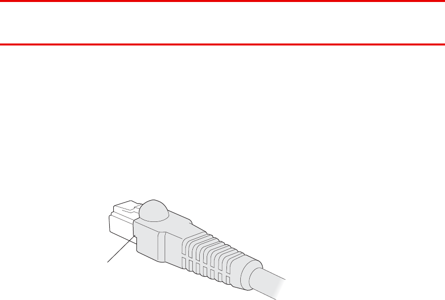
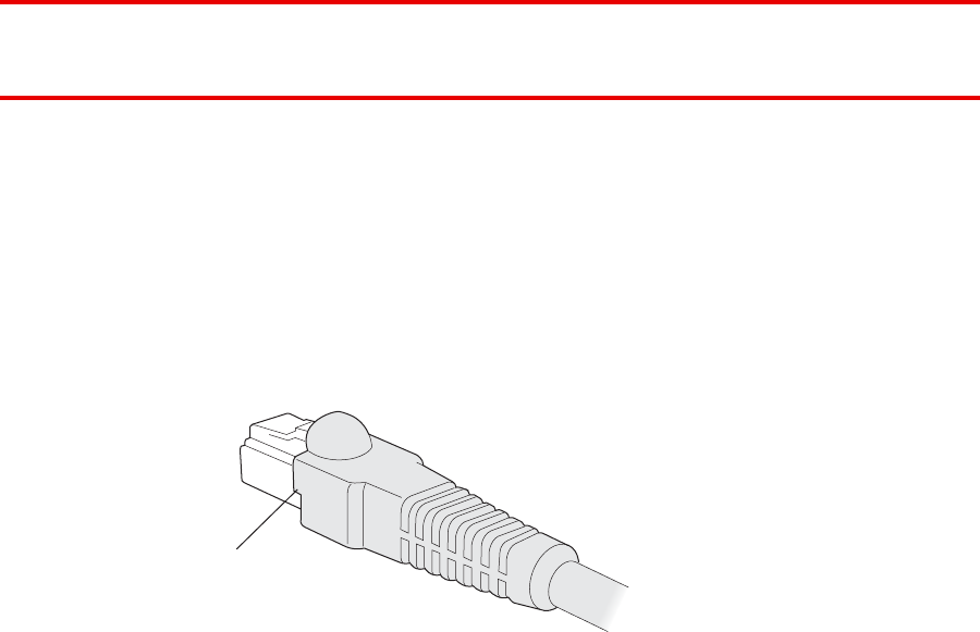
Cable requirements
The Ethernet ports on the access point cannot accept a CAT-5 cable that
has an uneven sheath as shown below. The RJ-45 connector on the cable
will not seat properly in the receptacle on the access point. Use a CAT-5
cable with an even sheath instead.
U
neven sheath
8
40-9502-0067
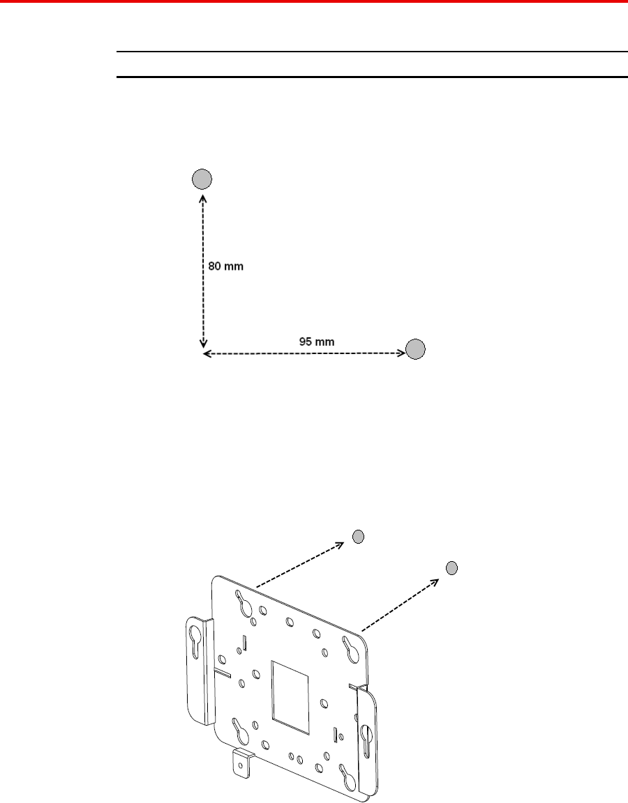
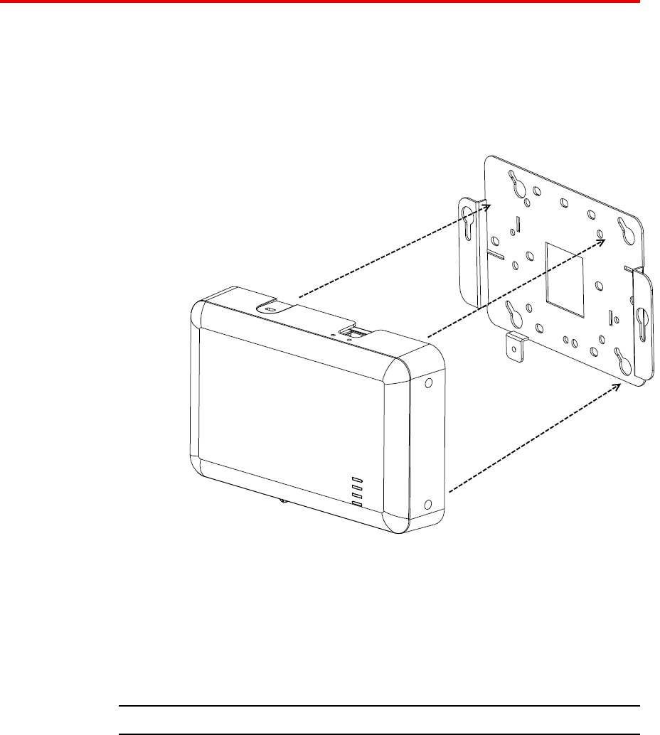
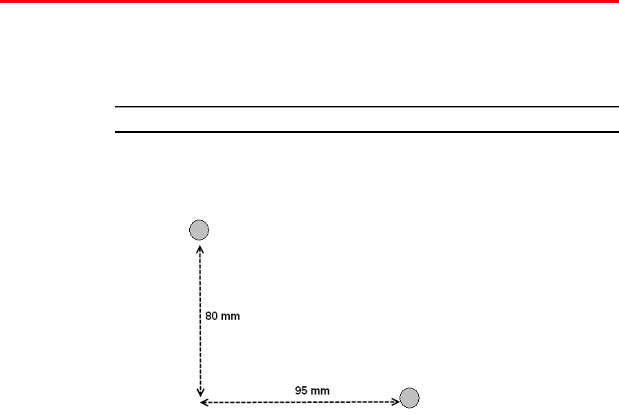
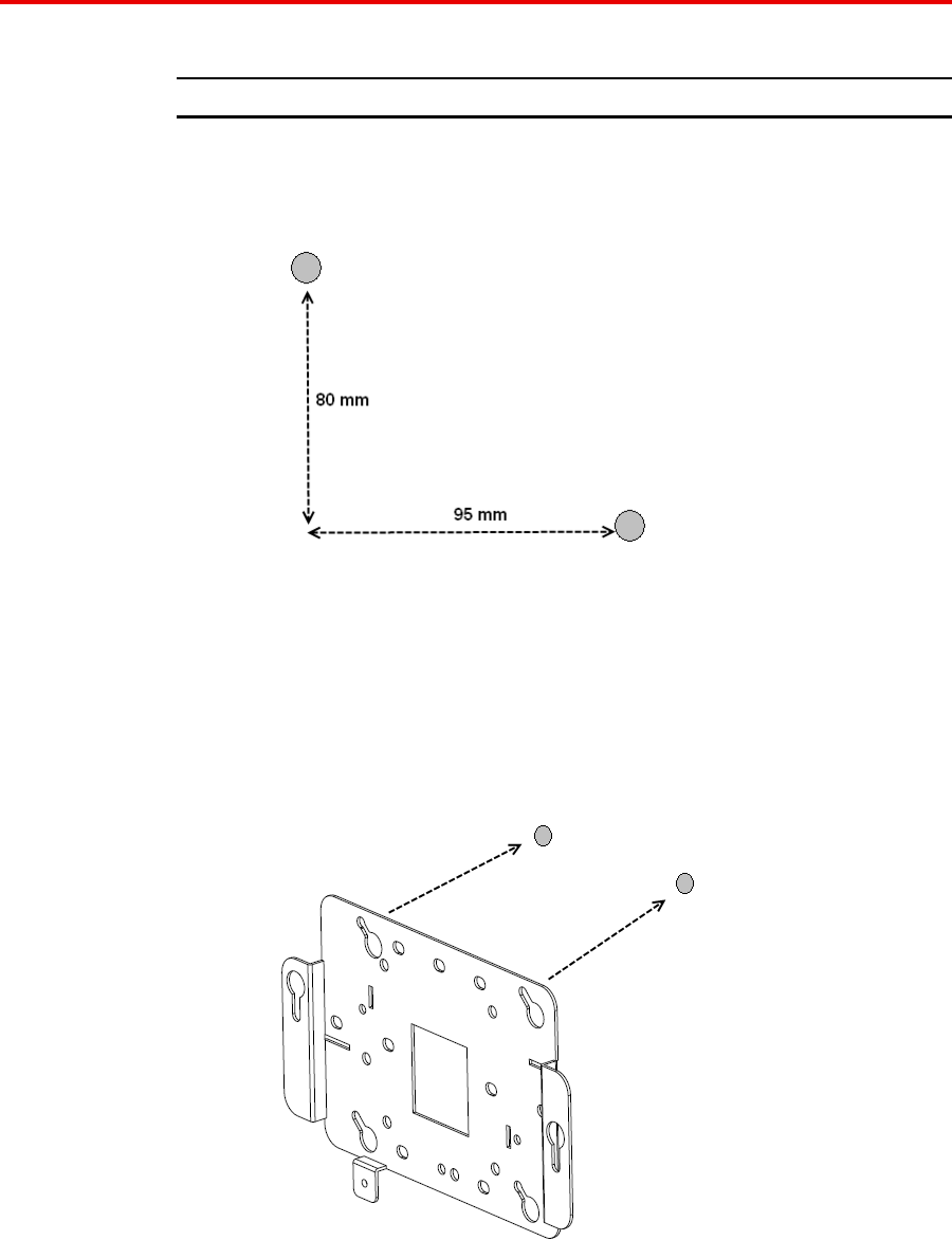
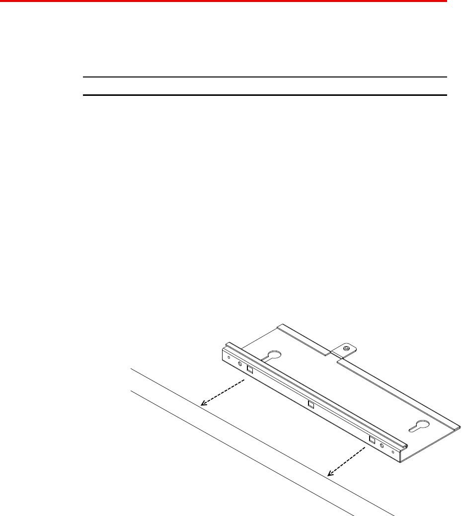
Mounting a wireless LAN access point on a wall
The mounting bracket is designed to use wall anchors with threaded
section diameters ranging between 3.5mm and 4.5mm. If wall anchors
have threaded diameters greater than 3.5mm, only the two mounting holes
marked ‘A’ may be used. If wall anchors have threaded diameters of less
than 3.5mm, the holes marked ‘A’ and the holes marked ‘B’ may be used.
All wall anchors must have a head diameter of less than 10mm or the wall
mounting bracket cannot be installed over them.
Perform the following procedure to mount a wireless LAN access point on
a wall:
Avaya WLAN 8100
Regulatory Information - AP 8120
NN47251-104 01.02 18 May 2010
.
18 English
Procedure steps
Step Action
1Locate the appropriate position of the wall anchors. The wall
anchors should be 95mm apart horizontally and 80mm apart
vertically.
The wall bracket is designed to use a minimum of 2 anchors and
a maximum of 4.
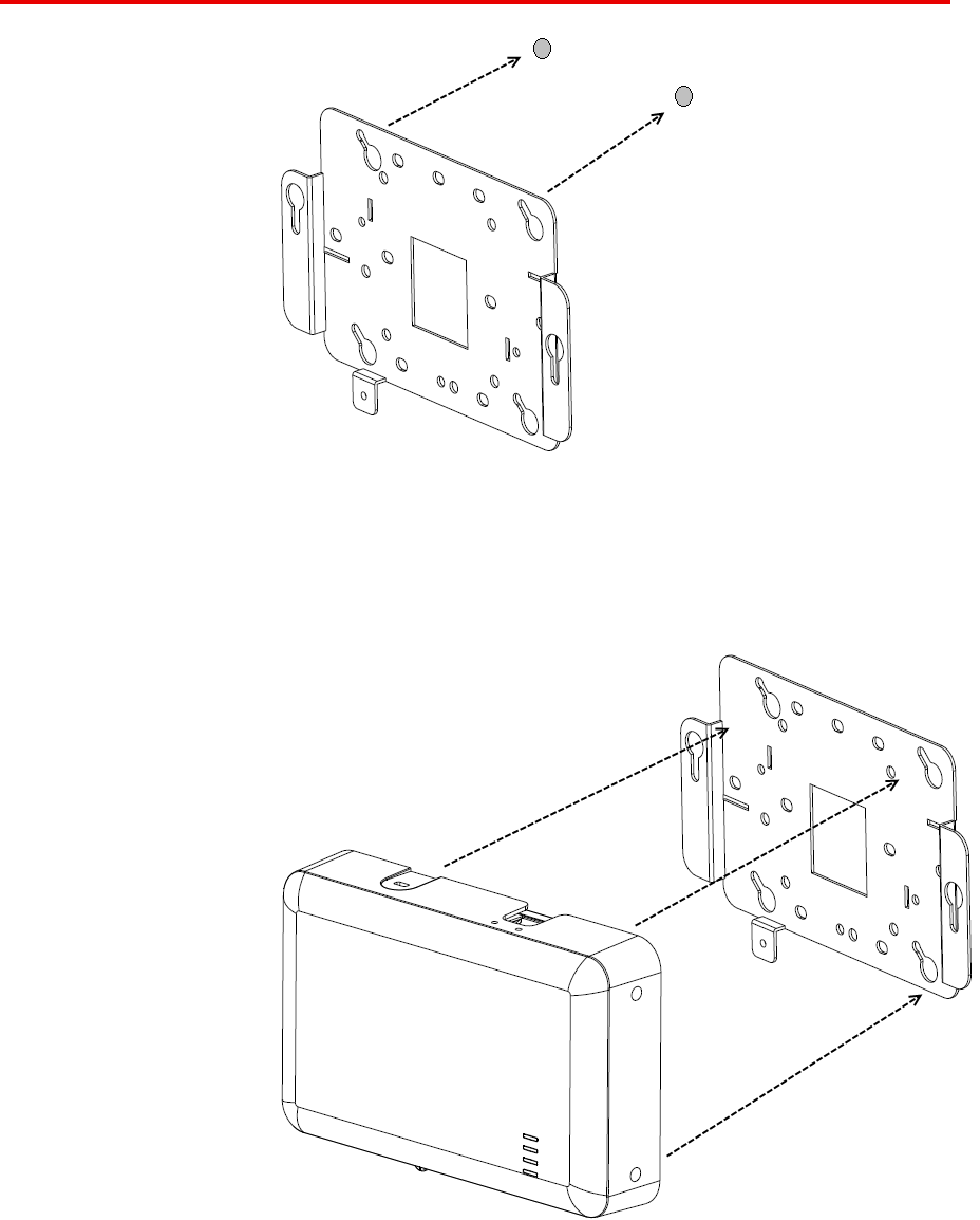
2Install the screws into the wall anchors but do not seat them fully,
leave at least a 2mm gap between the screw head and the wall.
3Slip the wall bracket over the heads of the screws and slide the
bracket to the right as viewed facing the wall.
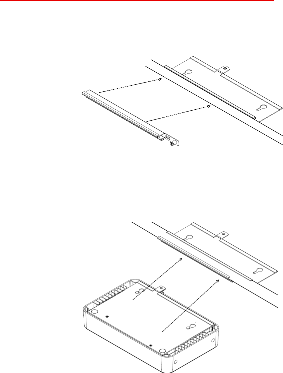
4Tighten the screws to secure the wall mounting bracket tightly
against the wall.
Avaya WLAN 8100
Regulatory Information - AP 8120
NN47251-104 01.02 18 May 2010
.

Installing an Access Point with a ceiling grid adaptor 19
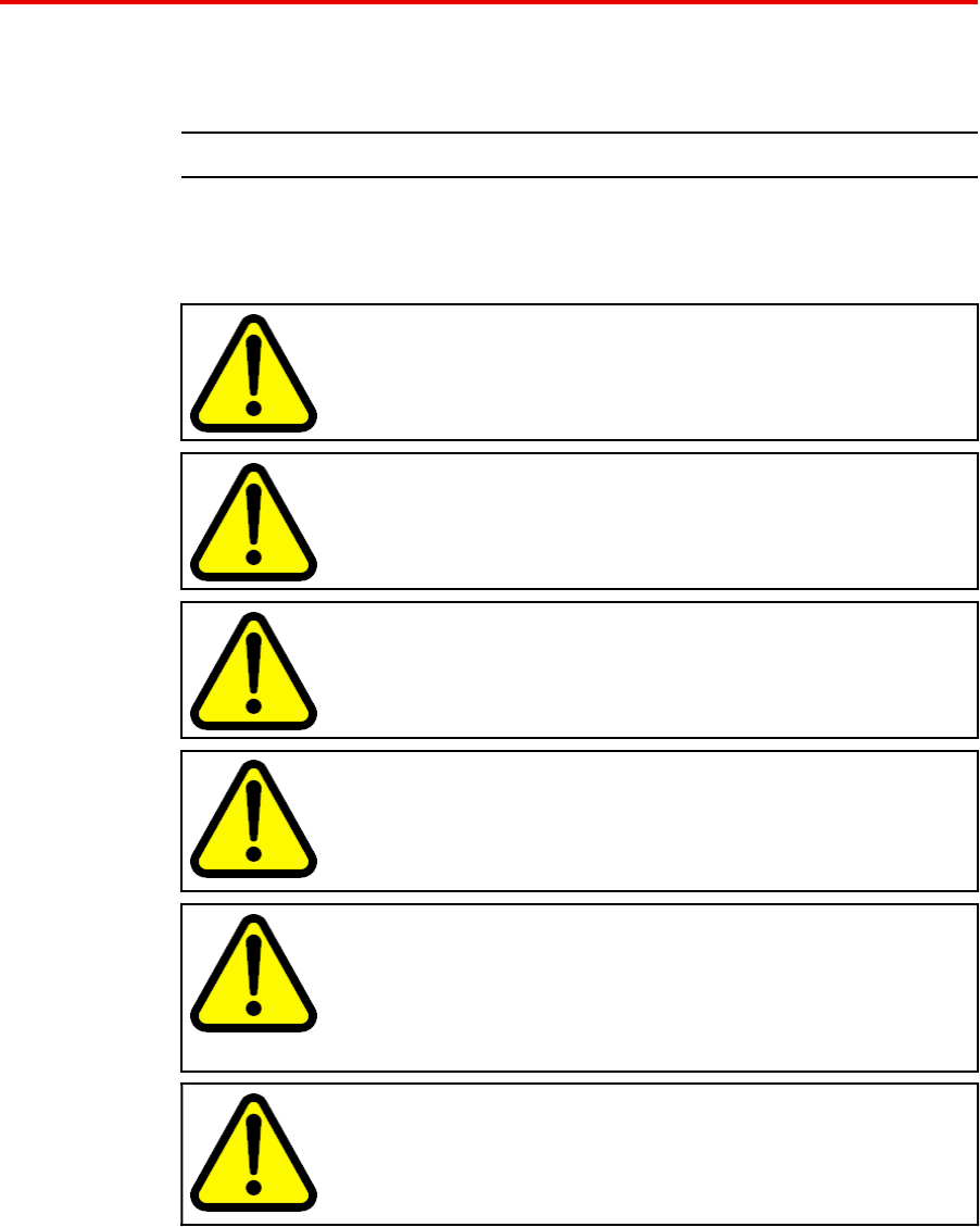
5Align the mounting tabs on the bottom of the access point sheet
metal enclosure with the vertically oriented keyhole slots in the
mounting bracket.
6Allow the access point to slide down the keyhole slots, making
sure the access point mounting tabs are seated at the bottom
of the slot.
7Secure the access point to the wall mounting bracket and tighten
the thumbscrews.
8Verify that the access point is secured to both the bracket and
to the wall.
--End--
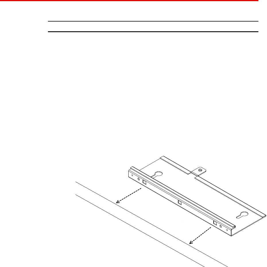
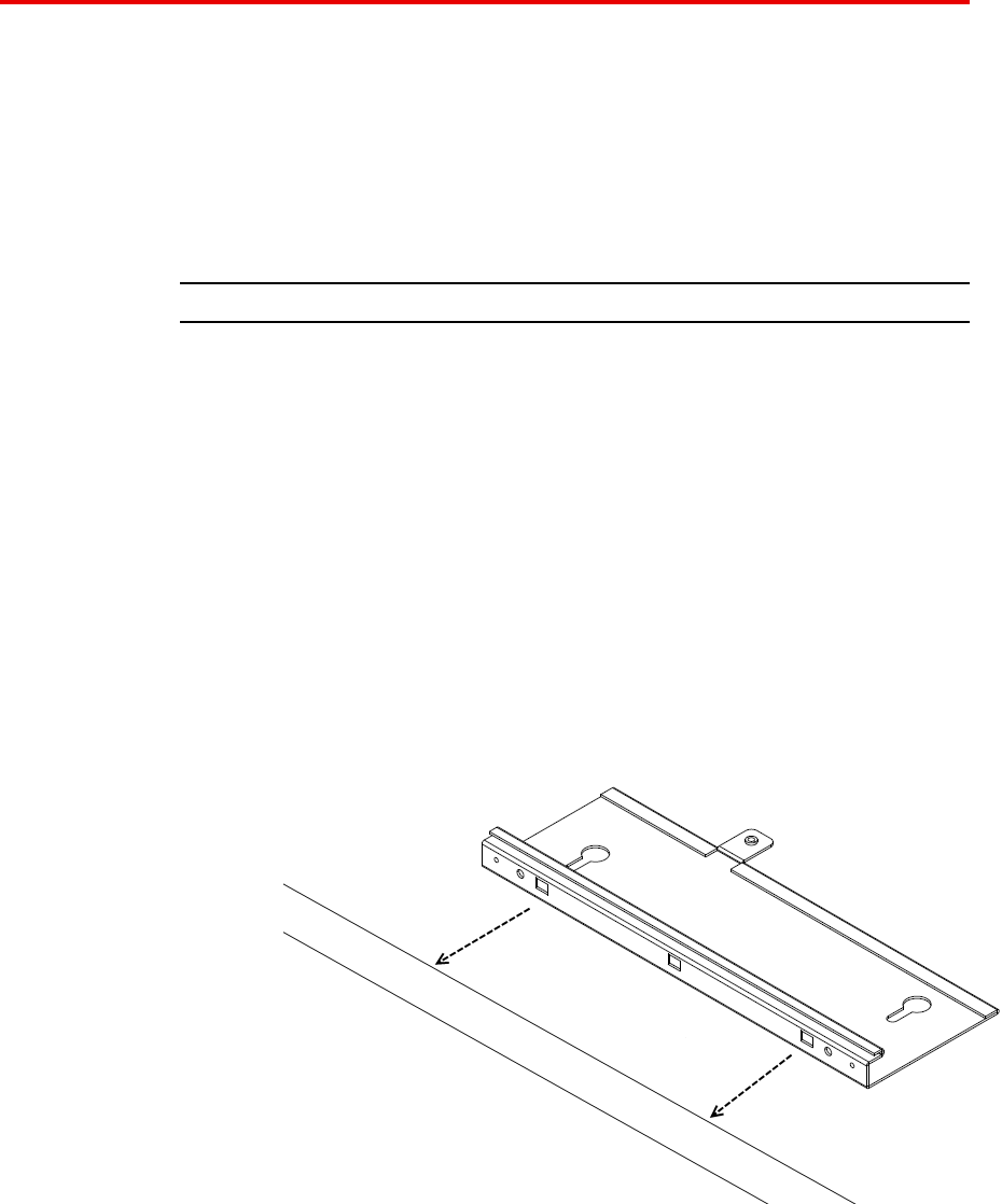
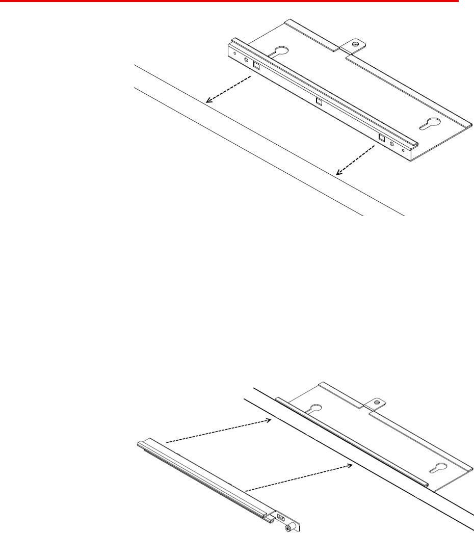
Installing an Access Point with a ceiling grid adaptor
The ceiling grid adaptor comes with two interlocking bracket parts. The
larger bracket includes keyhole shaped slots which mate with tabs on the
under surface of the AP and a threaded hole that mates with the captive
thumbscrew on the AP. The smaller bracket also includes a captive
fastener and it can be oriented with respect to the larger bracket in two
different ways corresponding to narrow or wide ceiling grids.
Perform the following procedure to install the access point with a ceiling
grid adaptor:
Avaya WLAN 8100
Regulatory Information - AP 8120
NN47251-104 01.02 18 May 2010
.
20 English
Procedure steps
Step Action
1Secure a safe work environment. Obtain a ladder that allows
easy access to the ceiling grid system.
2Identify an appropriate location on the ceiling grid where the
ceiling T-bars are safely accessible and where the ceiling tiles
can be temporarily elevated and cleared away from the work
area. The adaptor bracket assembly is intended for use with the
thin section grid runners, not the thicker section runners used to
cross large spans. To provide access for hands and tools, use a
pair of pencils or sticks to hold up the ceiling tiles out of the grid.
Doing this provides easy access for securing the bracket to the
grid.
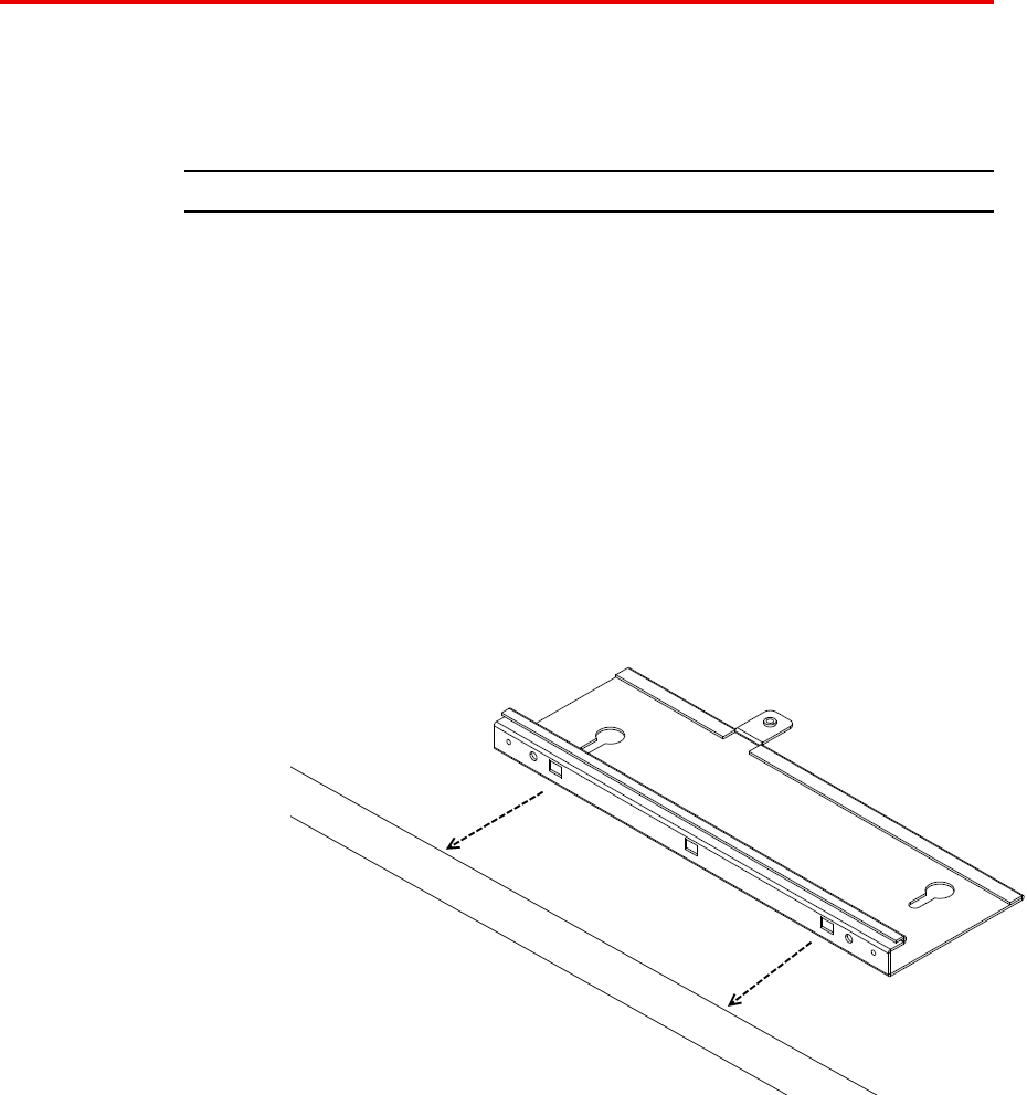
3Mount the larger bracket to the grid. While installing, pay
attention to the width of the grid strip in order to ascertain the
appropriate orientation for the smaller bracket which is installed
next.
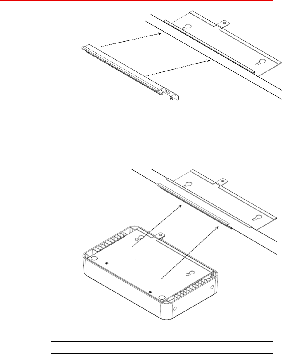
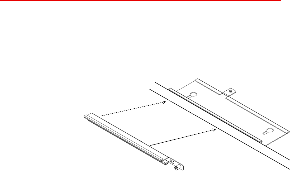
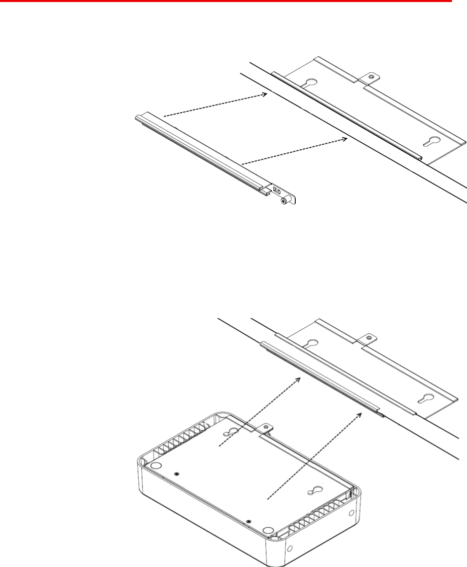
4Mount the interlocking small bracket to the large bracket and
clamp the two pieces together on the grid. The smaller bracket
has tabs formed into it which engage slots in the larger tab. This
allows the two parts to slide together and lock to one another.
When this is done, the two brackets effectively clamp themselves
around the ceiling grid. When the two halves of the bracket are
correctly slid together, the captive fastener in the small bracket
should engage threads provided in the larger bracket. Use a
screwdriver to screw down the captive fastener. Securing the
two brackets in this manner is essential to prevent them from
disengaging from one another. Tighten the captive fastener
screw securely.
Avaya WLAN 8100
Regulatory Information - AP 8120
NN47251-104 01.02 18 May 2010
.
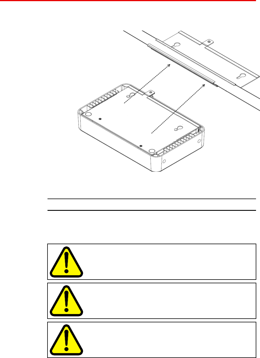
Installing an Access Point with a ceiling grid adaptor 21
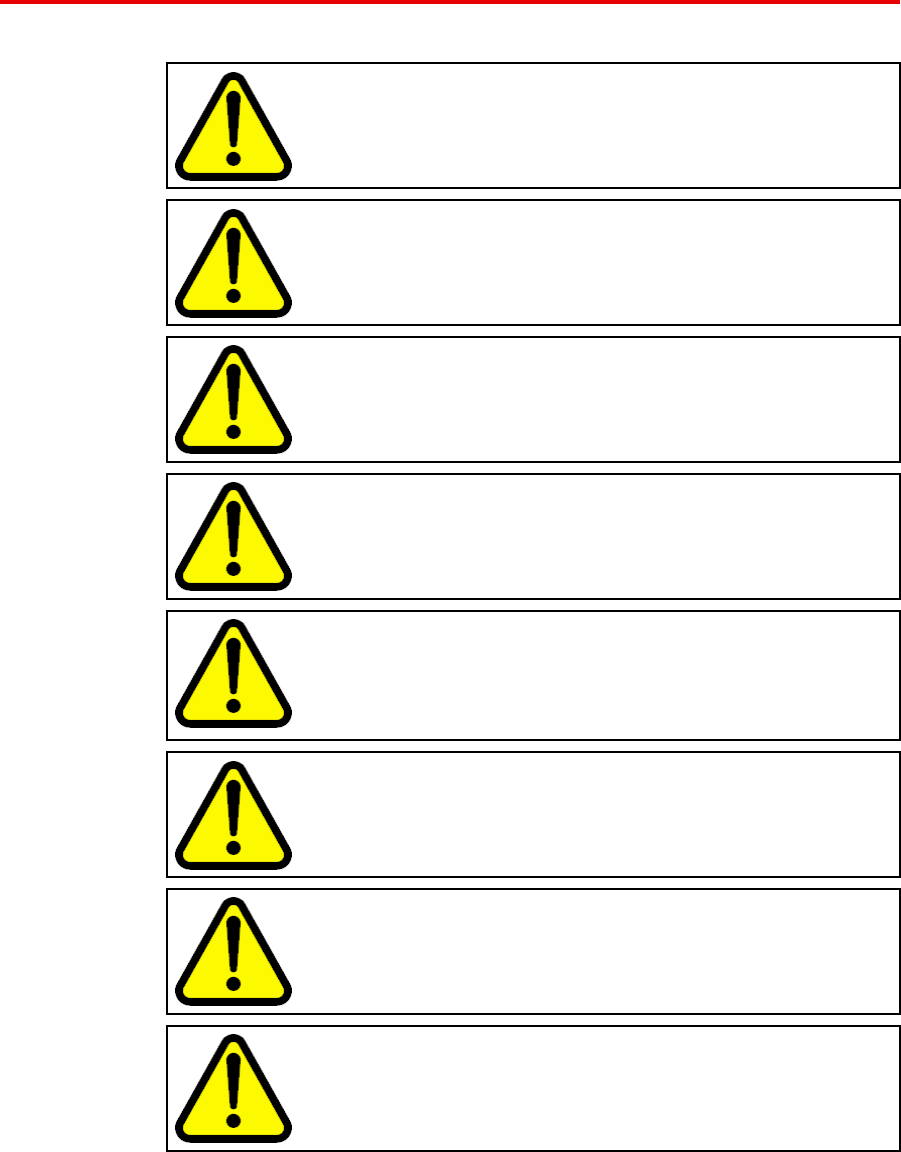
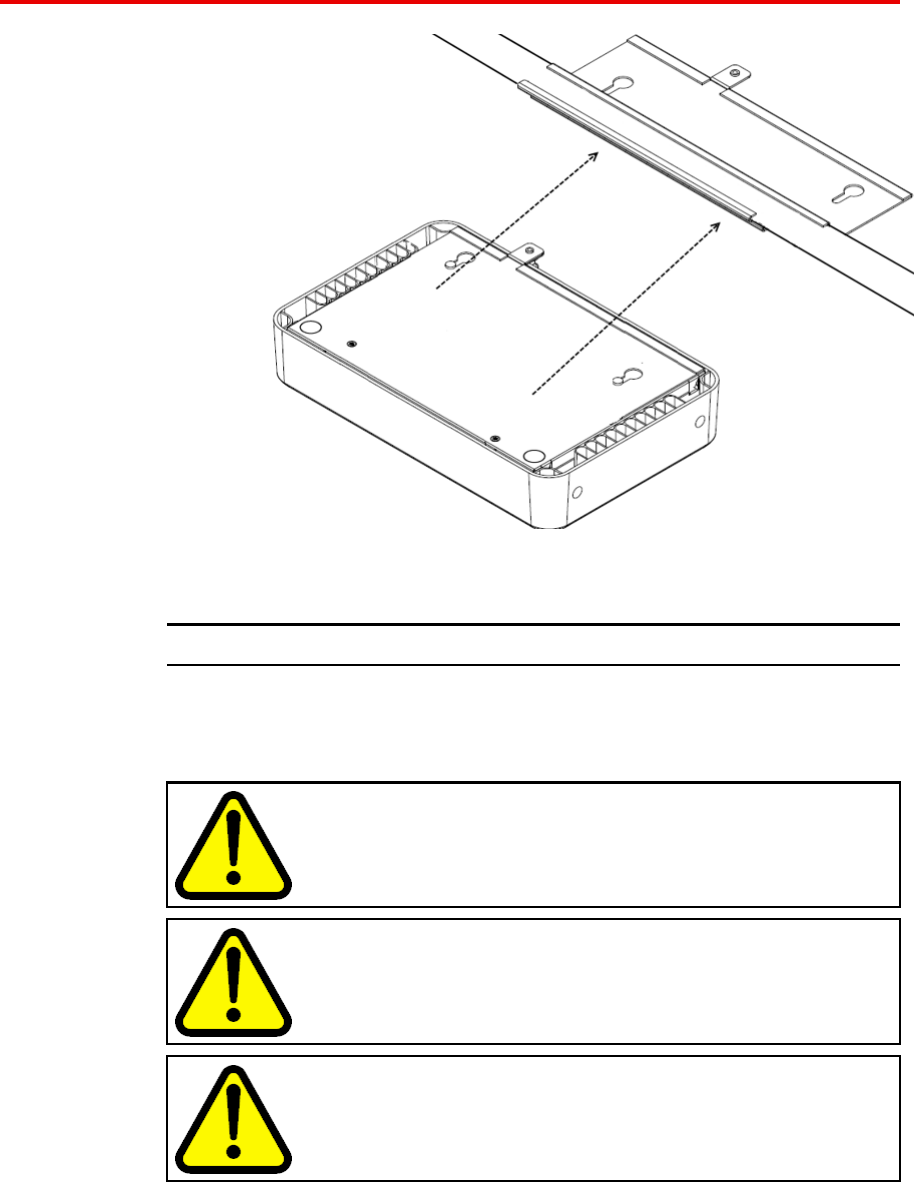
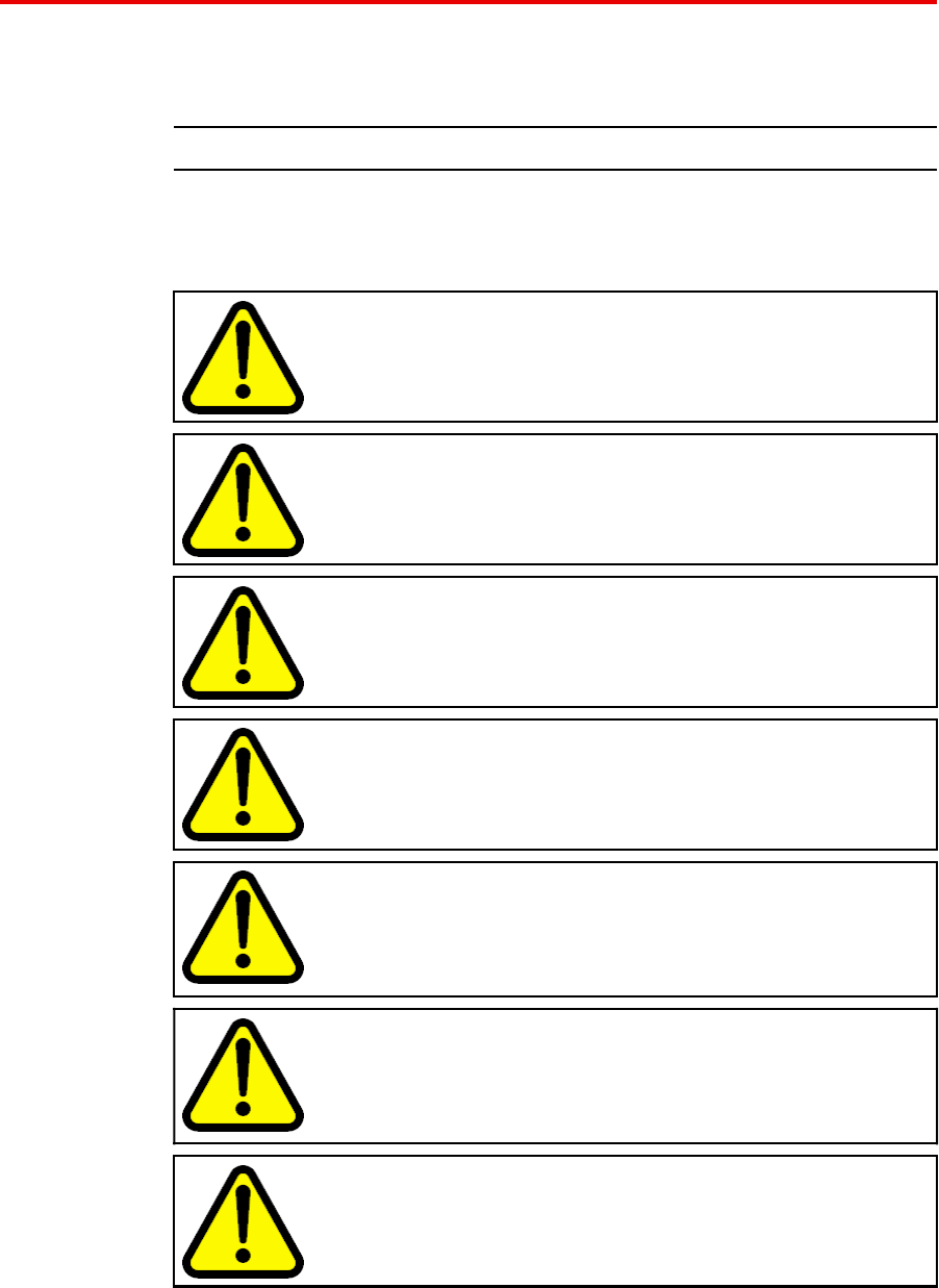
5Attach the access point to the bracket. Align the access point
securing tabs with the keyhole slots in the ceiling grid bracket
and carefully slide the access point onto the ceiling grid bracket
assembly. If the access point and the bracket assembly are
correctly engaged, it should be possible to engage the access
points captive thumbscrew into the threaded tab provided on the
ceiling grid bracket.
6Make electrical connections and return ceiling tiles.
--End--
Avaya WLAN 8100
Regulatory Information - AP 8120
NN47251-104 01.02 18 May 2010
.
22 English
Safety Messages
CAUTION
The Avaya WLAN Access Point 8120 radios are disabled by
default and can be enabled only by a system administrator.
WARNING
This situation or condition can cause injury.
WARNING
High voltage. This situation or condition can cause injury due
to electric shock.
WARNING
Only qualified service personnel must perform installation. Read
and follow all warning notices and instructions marked on the
product or included in the documentation.
WARNING
Install this device in such a manner as to maintain a minimum of
20 cm (7.9 inches) separation distance between the radiating
element(s) and all persons. This safety warning conforms with
FCC radio frequency exposure limits.
WARNING
Do not operate access point near unshielded blasting caps or in
an otherwise explosive environment unless the device has been
modified for such use by qualified personnel.
WARNING
Do not touch or move the access point when the antennas are
transmitting or receiving.
WARNING
Before using a wireless device in a hazardous location, consult
the local codes, national codes, and safety directors of the
location for usage constraints.
Avaya WLAN 8100
Regulatory Information - AP 8120
NN47251-104 01.02 18 May 2010
.

23
.
Deutsch
Verwenden Sie die folgenden Verfahren und Informationen zur Installation
der Access Points Avaya AP 8120-R00 und AP 8120-R06.
Kabelanschlüsse
Die Ethernet-Ports an den Access Points können nicht mit CAT 5-Kabeln
mit einer abgesetzten Kabelhülse verbunden werden (siehe unten). Der
RJ-45-Anschluss des Kabels sitzt in diesem Fall nicht richtig auf dem Port
des Access Points auf. Verwenden Sie stattdessen ein CAT 5-Kabel mit
einer geraden Kabelhülse.
U
neven sheath
8
40-9502-0067
Wandmontage eines Wireless LAN Access Points
Die Wandhalterung wird mit Wanddübeln mit einem Gewindedurchmesser
von 3,5-4,5 mm befestigt. Verwenden Sie bei Gewindedurchmessern
über 3,5 mm lediglich die beiden mit A“ markierten Montagelöcher der
Wandhalterung. Bei Gewindedurchmessern unter 3,5 mm können Sie
die mit A“ und die mit B“ markierten Montagelöcher verwenden. Der
Kopfdurchmesser der Wanddübel muss kleiner als 10 mm sein, damit die
Wandhalterung richtig montiert werden kann.
So führen Sie die Wandmontage eines Wireless LAN Access Points durch:
Avaya WLAN 8100
Regulatory Information - AP 8120
NN47251-104 01.02 18 May 2010
.

24 Deutsch
Procedure steps
Step Action
1Bestimmen Sie die richtige Position der Wanddübel. Die
Wanddübel müssen waagerecht in einem Abstand von 95 mm
und senkrecht in einem Abstand von 80 mm installiert werden.
Die Wandhalterung wird mit mindestens 2 und höchstens 4
Dübeln befestigt.
2Drehen Sie die Schrauben in die Wanddübel, ohne sie ganz
festzuziehen. Lassen Sie einen Abstand von mindestens 2 mm
zwischen dem Schraubenkopf und der Wand.
3Setzen Sie die Wandhalterung auf die Schraubenköpfe auf.
Schieben Sie die Halterung nach rechts (von Ihnen aus
gesehen).
Avaya WLAN 8100
Regulatory Information - AP 8120
NN47251-104 01.02 18 May 2010
.
Deckenmontage eines Access Points (Rasterdecke) 25
4Ziehen Sie die Schrauben an, um die Wandhalterung sicher an
der Wand zu befestigen.
5Richten Sie die Montagelaschen unten am Metallgehäuse des
Access Points mit den senkrechten Längsschlitzen an der
Wandhalterung aus.
6Schieben Sie den Access Point vorsichtig in den Längsschlitzen
nach unten, sodass die Montagelaschen des Access Points am
unteren Rand der Längsschlitze aufsitzen.
7Befestigen Sie den Access Point an der Wandhalterung, und
ziehen Sie die Daumenschrauben an.
8Überprüfen Sie, ob der Access Point sicher an der
Wandhalterung und an der Wand angebracht ist.
--End--
Deckenmontage eines Access Points (Rasterdecke)
Der Adapter für die Deckenmontage verfügt über zwei ineinander
greifende Halterungen. Die Montagelaschen unten am Access Point
passen in die Längsschlitze an der größeren Halterung. Die unverlierbare
Schraube am Access Point wird in das Gewindeloch an der größeren
Avaya WLAN 8100
Regulatory Information - AP 8120
NN47251-104 01.02 18 May 2010
.
26 Deutsch
Haltung geschraubt. Die unverlierbare Schraube an der kleineren
Halterung kann je nach Rastergröße auf zweierlei Weise an der größeren
Halterung ausgerichtet werden.
So führen Sie die Deckenmontage eines Access Points an einer
Rasterdecke durch:
Procedure steps
Step Action
1Sorgen Sie für eine sichere Arbeitsumgebung. Besorgen Sie sich
eine Leiter, die Zugang zur Rasterdecke ermöglicht.
2Bestimmen Sie eine geeignete Montageposition an der
Rasterdecke, an der die T-Profile sicher zugänglich sind und
die Deckenplatten vorübergehend abgehängt werden können.
Der Adapter für die Deckenmontage wird an den dünneren
Querschienen befestigt, nicht an den dickeren und längeren
Haupttrageschienen. Um ungehindert arbeiten zu können, heben
Sie die Deckenplatten mit zwei Stiften oder Stäben nach oben
aus dem Deckenraster. So erhalten Sie einfachen Zugang zum
Befestigen der Halterung.
3Befestigen Sie die größere Halterung am Deckenraster.
Achten Sie dabei auf die Breite der Schiene, um die richtige
Positionierung für die kleinere Halterung zu bestimmen, die
anschließend installiert wird.
4Montieren Sie die kleinere Halterung so an der größeren, dass
sie ineinander greifen, und klemmen Sie die beiden Halterungen
zusammen. Die Montagelaschen an der kleineren Halterung
passen in die Schlitze an der größeren Halterung. So können die
Avaya WLAN 8100
Regulatory Information - AP 8120
NN47251-104 01.02 18 May 2010
.
Deckenmontage eines Access Points (Rasterdecke) 27
beiden Halterungen sicher arretiert und um die Deckenschiene
herum montiert werden. Wenn Sie die beiden Halterungen richtig
miteinander verbunden haben, passt die unverlierbare Schraube
an der kleineren Halterung in das Gewinde in der größeren
Halterung. Sichern Sie die unverlierbare Schraube mit einem
Schraubendreher. Es ist sehr wichtig, die beiden Halterungen
auf diese Weise zu sichern, damit sie sich nicht voneinander
lösen. Ziehen Sie die unverlierbare Schraube fest an.
5Befestigen Sie den Access Point an der Halterung. Richten Sie
die Sicherungslaschen am Access Point an den Längsschlitzen
an der Deckenhalterung aus, und schieben Sie den Access Point
vorsichtig auf die montierte Deckenhalterung. Wenn der Access
Point richtig auf die Deckenhalterung aufgesetzt ist, kann die
unverlierbare Daumenschraube auf dem Access Point in das
Gewinde an der Deckenhalterung geschraubt werden.
Avaya WLAN 8100
Regulatory Information - AP 8120
NN47251-104 01.02 18 May 2010
.
28 Deutsch
6Stellen Sie die elektrischen Verbindungen her, und bringen Sie
die Deckenplatten wieder an.
--End--
Sicherheitshinweise
Wir benötigen Übersetzungen für diese Meldungen und alle anderen
Meldungen, die wir dem Dokument hinzufügen möchten.
CAUTION
Die Frequenzempfänger für den Avaya WLAN Access
Point 8120 sind standardmäßig deaktiviert und können nur von
einem Systemadministrator aktiviert werden.
WARNING
Dieser Zustand bzw. diese Bedingung kann zu Verletzungen
führen.
WARNING
Hochspannung. Dieser Zustand bzw. diese Bedingung kann
aufgrund von Stromschlag zu Verletzungen führen.
Avaya WLAN 8100
Regulatory Information - AP 8120
NN47251-104 01.02 18 May 2010
.
Sicherheitshinweise 29
WARNING
Die Installation darf nur von qualifiziertem Wartungspersonal
durchgeführt werden. Lesen Sie alle Warnhinweise und
Anweisungen auf dem Gerät bzw. in der Dokumentation.
WARNING
Installieren Sie das Gerät so, dass zwischen den
Strahlungselementen und allen Personen ein Abstand von
mindestens 20 cm gewährleistet ist. Diese Sicherheitswarnung
entspricht den FCC-Grenzwerten für Hochfrequenzstrahlung.
WARNING
Setzen Sie den Access Point nicht in der Nähe von
ungeschützten Zündkapseln oder in anderen Umgebungen
mit Explosionsgefahr ein, es sei denn, das Gerät wurde von
qualifiziertem Personal für einen solchen Einsatz modifiziert.
WARNING
Berühren oder bewegen Sie den Access Point nicht beim
Senden oder Übertragen von Funksignalen.
WARNING
Informieren Sie sich vor der Verwendung eines Wireless-Geräts
in einer Gefahrenumgebung über regionale und überregionale
Vorschriften zu Nutzungsbeschränkungen sowie die
Sicherheitsrichtlinien für den jeweiligen Standort.
Avaya WLAN 8100
Regulatory Information - AP 8120
NN47251-104 01.02 18 May 2010
.

30 Deutsch
Avaya WLAN 8100
Regulatory Information - AP 8120
NN47251-104 01.02 18 May 2010
.
31
.
Español
Al momento de instalar los puntos de acceso AP 8120-R00 y AP
8120-R06 de Avaya, tenga en cuenta el procedimiento y la información
que se presentan a continuación.
Requisitos del cable
Los puertos Ethernet del punto de acceso no admiten cables CAT-5 con
terminación de recubrimiento irregular, como el que se muestra en la
siguiente imagen. En caso de usar uno de estos cables, el conector RJ-45
no encajará bien en la toma del punto de acceso. En su lugar, utilice
cables CAT-5 con terminación de recubrimiento uniforme.
U
neven sheath
8
40-9502-0067
Montaje en la pared de un punto de acceso inalámbrico para redes
LAN El soporte de montaje está concebido para adosarse a la pared con tacos
para pared (también denominados "tarugos" o "taquetes") cuyas secciones
roscadas presenten un diámetro de entre 3,5 y 4,5 mm. Si los tacos para
pared cuentan con diámetros de rosca superiores a 3,5 mm, sólo pueden
utilizarse los dos orificios marcados con la letra A. En cambio, si los tacos
cuentan con diámetros de rosca inferiores a 3,5 mm, pueden utilizarse
tanto los orificios marcados con la letra A como los marcados con la letra
B. El diámetro de la cabeza de los tacos no debe exceder los 10 mm;
en caso contrario, no podrán pasarse por los orificios del soporte para la
instalación.
Avaya WLAN 8100
Regulatory Information - AP 8120
NN47251-104 01.02 18 May 2010
.
32 Español
A continuación, se presentan los pasos para montar en una pared un
punto de acceso inalámbrico para redes LAN:
Procedure steps
Step Action
1Encuentre el lugar indicado para poner los tacos. La distancia
entre los tacos debe ser de 95 mm en sentido horizontal y de
80 mm en sentido vertical.
El soporte de pared puede adosarse con un mínimo de 2 tacos
y con un máximo de 4.
2Cuando llegue el momento de colocar los tornillos en los tacos,
no los atornille del todo: deje un espacio de al menos 2 mm
entre la cabeza del tornillo y la pared.
3Coloque el soporte de pared por sobre las cabezas de los
tornillos y muévalo hacia la derecha (desde la perspectiva de
alguien ubicado de frente a la pared).
Avaya WLAN 8100
Regulatory Information - AP 8120
NN47251-104 01.02 18 May 2010
.
Montaje en la pared de un punto de acceso inalámbrico para redes LAN 33
4Termine de ajustar los tornillos hasta que el soporte quede bien
sujeto contra la pared.
5Alinee las lengüetas de montaje ubicadas en la parte inferior de
la caja metálica del punto de acceso con las ranuras verticales
con forma de cerradura del soporte de montaje.
6Inserte el punto de acceso y llévelo hacia abajo hasta que las
lengüetas de montaje queden apoyadas en el extremo inferior de
las ranuras con forma de cerradura.
Avaya WLAN 8100
Regulatory Information - AP 8120
NN47251-104 01.02 18 May 2010
.

34 Español
7Asegure el punto de acceso en el soporte de montaje y apriete
los tornillos de ajuste manual.
8Asegúrese de que el punto de acceso quede bien sujeto tanto al
soporte como a la pared.
--End--
Instalación de un punto de acceso con un adaptador para
estructuras de techos desmontables
El adaptador para estructuras de techos desmontables incluye un soporte
de dos piezas que van conectadas entre sí. La pieza más grande tiene
ranuras con forma de cerradura que coinciden con lengüetas ubicadas en
la superficie inferior del punto de acceso, además de contar con un orificio
roscado para el tornillo imperdible de ajuste manual del punto de acceso.
La más pequeña también incluye un tornillo imperdible y puede orientarse
de dos maneras distintas con respecto a la pieza de mayor tamaño a fin
de adaptarse a estructuras de techos desmontables angostas y anchas .
Para instalar el punto de acceso con un adaptador para estructuras de
techos desmontables, siga los pasos que se presentan a continuación:
Procedure steps
Step Action
1Tome las medidas necesarias para garantizar la seguridad del
lugar de trabajo. Consiga una escalera que le permita llegar
fácilmente a la estructura del techo desmontable.
2Localice un lugar adecuado en la estructura del techo
desmontable donde pueda accederse sin correr riesgos a los
perfiles en T y donde las placas del cielorraso puedan levantarse
y quitarse momentáneamente del sector de trabajo. El adaptador
sirve para perfiles delgados de techos desmontables, no para
los perfiles más gruesos que se utilizan para cubrir distancias
mayores. A fin de poder acceder al punto de instalación, utilice
un par de lápices o palitos para mantener levantadas las placas
del cielorraso de la estructura. De esta manera, resulta fácil
llegar con las manos y las herramientas para sujetar bien el
soporte a la estructura.
3Coloque la pieza más grande en la estructura. Mientras lo hace,
fíjese cuál es el ancho del perfil con objeto de determinar la
orientación adecuada de la pieza pequeña, que debe instalarse
a continuación.
Avaya WLAN 8100
Regulatory Information - AP 8120
NN47251-104 01.02 18 May 2010
.
Instalación de un punto de acceso con un adaptador para estructuras de techos desmontables 35
4Monte la pieza pequeña en la grande y ajuste ambas a la
estructura. La pieza pequeña cuenta con lengüetas que encajan
en ranuras ubicadas en la pieza más grande. Por ende, al
poner una contra la otra, ambas piezas quedan conectadas y se
sujetan con firmeza a la estructura del techo desmontable. Si
ambas piezas del adaptador quedaron bien colocadas, el tornillo
imperdible de la pieza pequeña tiene que quedar alineado con el
orificio roscado de la pieza grande. Utilice un destornillador para
ajustar el tornillo imperdible. Es muy importante sujetar ambas
piezas del soporte de esta manera para impedir que se suelten.
Ajuste bien el tornillo imperdible.
5Monte el punto de acceso en el soporte. Alinee las lengüetas
del punto de acceso con las ranuras con forma de cerradura del
adaptador para estructuras de techos desmontables e inserte
con cuidado el punto de acceso en el adaptador. Si tanto el
punto de acceso como el adaptador están bien colocados,
el tornillo imperdible de ajuste manual del punto de acceso
Avaya WLAN 8100
Regulatory Information - AP 8120
NN47251-104 01.02 18 May 2010
.
36 Español
tiene que coincidir con la lengüeta roscada del adaptador para
estructuras de techos desmontables. Ajústelo.
6Realice las conexiones eléctricas necesarias y vuelva a colocar
las placas del cielorraso.
--End--
Advertencias de seguridad
We need translations for these messages and any others we want to add
to the document.
CAUTION
Las radios del punto de acceso WLAN 8120 de Avaya se
encuentran desactivadas de manera predeterminada, y sólo
puede activarlas un administrador de sistemas.
WARNING
Esta situación o estado puede provocar lesiones.
WARNING
Alta tensión. Esta situación o estado puede provocar lesiones
por descarga eléctrica.
Avaya WLAN 8100
Regulatory Information - AP 8120
NN47251-104 01.02 18 May 2010
.
Advertencias de seguridad 37
WARNING
La instalación debe dejarse en manos de personal de servicio
técnico especializado. Lea y respete todas las advertencias de
seguridad e instrucciones que figuren en el producto o en la
documentación pertinente.
WARNING
Instale este dispositivo de modo que quede una separación
de como mínimo 20 cm (7,9 pulg.) entre las personas y todo
lo que emita señales de radiofrecuencia. Esta advertencia de
seguridad se ajusta a los límites de exposición a señales de
radiofrecuencia que dicta la FCC.
WARNING
No utilice el punto de acceso cerca de detonadores sin blindaje
ni en ningún tipo de lugar en que exista riesgo de explosión a
menos que personal especializado haya adaptado el dispositivo
para dicho fin.
WARNING
No toque ni mueva el punto de acceso cuando las antenas
estén transmitiendo o recibiendo información.
WARNING
Antes de utilizar un dispositivo inalámbrico en un entorno
peligroso, familiarícese con las normativas locales y nacionales,
y consulte al encargado de seguridad del lugar para estar al
tanto de los usos permitidos.
Avaya WLAN 8100
Regulatory Information - AP 8120
NN47251-104 01.02 18 May 2010
.

38 Español
Avaya WLAN 8100
Regulatory Information - AP 8120
NN47251-104 01.02 18 May 2010
.

39
.
Français
Utilisez les procédures et informations suivantes lors de l’installation des
points d’accès AP 8120-R00 et AP 8120-R06 d’Avaya.
Configuration requise pour les câbles
Les câbles CAT-5 dotés d’une gaine irrégulière, comme illustré ci-dessous,
ne sont pas adaptés aux ports Ethernet du point d’accès. Sur ce type de
câble, le connecteur RJ-45 ne s’insère pas correctement dans le logement
du point d’accès. Utilisez plutôt un câble CAT-5 doté d’une gaine régulière.
U
neven sheath
8
40-9502-0067
Montage mural du point accès WLAN
Le support de montage est conçu pour utiliser des dispositifs d’ancrage au
mur équipés de diamètres de filetage de sections allant de 3,5 à 4,5 mm.
Si le diamètre de filetage des dispositifs d’ancrage au mur est supérieur à
3,5 mm, seuls les deux trous de montage marqués par la lettre A peuvent
être utilisés. Si le diamètre de filetage des dispositifs d’ancrage au mur
est inférieur à 3,5 mm, les trous marqués par les lettres A et B peuvent
être utilisés. Tous les dispositifs d’ancrage au mur doivent posséder un
diamètre de tête inférieur à 10 mm, sinon ils ne peuvent pas prendre en
charge l’installation du support de montage mural.
Pour monter un point d’accès WLAN sur un mur, procédez comme suit :
Avaya WLAN 8100
Regulatory Information - AP 8120
NN47251-104 01.02 18 May 2010
.
40 Français
Procedure steps
Step Action
1Localisez l’emplacement adéquat pour les dispositifs d’ancrage
au mur. Les dispositifs d’ancrage au mur doivent être écartés de
95 mm horizontalement et 80 mm verticalement.
Le support mural est conçu pour utiliser entre 2 et 4 dispositifs
d’ancrage.
2Insérez les vis dans les dispositifs d’ancrage au mur sans les
serrer complètement : laissez un espace de 2 mm au moins
entre la tête de la vis et le mur.
3Glissez le support mural sur les têtes des vis, puis faites-le
glisser vers la droite (en regardant le mur).
4Serrez les vis afin de fixer solidement le support de montage
mural au mur.
Avaya WLAN 8100
Regulatory Information - AP 8120
NN47251-104 01.02 18 May 2010
.

Installation du point accès avec un adaptateur pour grille de plafond 41
5Alignez les languettes de montage de la partie inférieure du
boîtier en tôle du point d’accès avec les encoches en trous de
serrure du support de montage, orientées à la verticale.
6Faites glisser le point d’accès dans les encoches en trous de
serrure en veillant à ce que ses languettes de montage soient
correctement installées dans la partie inférieure des encoches.
7Fixez solidement le point d’accès au support de montage mural
et serrez les vis.
8Vérifiez que le point d’accès est solidement fixé au support et
au mur.
--End--
Installation du point accès avec un adaptateur pour grille de
plafond L’adaptateur pour grille de plafond est fourni avec deux pièces de support
croisées. Le grand support est doté d’encoches en trous de serrure,
adaptées aux languettes situées sur la face inférieure du point d’accès, et
d’un trou taraudé adapté à la vis captive du point d’accès. Le petit support
est également doté d’une fixation captive et peut être orienté dans deux
directions différentes par rapport au grand support, s’adaptant ainsi aux
grilles de plafond étroites ou larges.
Avaya WLAN 8100
Regulatory Information - AP 8120
NN47251-104 01.02 18 May 2010
.
42 Français
Pour installer le point d’accès avec un adaptateur pour grille de plafond,
procédez comme suit :
Procedure steps
Step Action
1Sécurisez votre environnement de travail. Munissez-vous d’une
échelle afin d’accéder facilement à la grille de plafond.
2Déterminez un emplacement approprié sur la grille de plafond
où les barres en T sont accessibles en toute sécurité et où les
dalles de plafond peuvent être temporairement soulevées et
retirées de l’espace de travail. Le dispositif d’adaptateur de
support est conçu pour être utilisé avec les coulisseaux de la
grille de la section fine et non avec ceux de la section plus
épaisse, conçus pour le croisement des grandes travées. Afin
de disposer d’espace pour vos mains et vos outils, utilisez
des crayons ou des bâtonnets pour maintenir les dalles de
plafond éloignées de la grille. Ainsi, vous bénéficiez d’une large
ouverture pour fixer le support à la grille.
3Montez le grand support sur la grille. Lors de l’installation, prêtez
attention à la largeur du lattis afin de déterminer l’orientation
appropriée pour l’installation du petit support à l’étape suivante.
4Montez le petit support croisé sur le grand support et serrez
les deux éléments ensemble sur la grille. Le petit support
est doté de languettes qui dans lesquelles s’insèrent les
encoches du grand support. Ainsi, les deux éléments glissent
simultanément et sont maintenus l’un contre l’autre. Une fois
cette action effectuée, les deux supports sont resserrés sur la
grille de plafond. Lorsque les deux moitiés du support coulissent
correctement l’une contre l’autre, les filets du grand support
Avaya WLAN 8100
Regulatory Information - AP 8120
NN47251-104 01.02 18 May 2010
.
Installation du point accès avec un adaptateur pour grille de plafond 43
doivent s’insérer dans la fixation captive du petit support. Utilisez
un tournevis pour serrer la fixation captive. Il est indispensable
de fixer les deux supports de cette manière afin d’éviter qu’ils
ne se détachent l’un de l’autre. Serrez solidement la vis de la
fixation captive.
5Fixez le point d’accès au support. Alignez les languettes de
fixation du point d’accès avec les encoches en trous de serrure
du support de la grille de plafond, puis faites glisser le point
d’accès sur le dispositif de support de la grille de plafond
avec soin. Si le point d’accès et le système de support sont
correctement rattachés, il doit être possible d’insérer la vis
captive du point d’accès dans la languette filetée du support de
la grille de plafond.
Avaya WLAN 8100
Regulatory Information - AP 8120
NN47251-104 01.02 18 May 2010
.
44 Français
6Effectuez les raccordements électriques et remettez les dalles de
plafond en place.
--End--
Messages de sécurité
Ces messages ainsi que tout autre message ajouté à ce document doivent
être traduits.
CAUTION
Les radios des points d’accès 8120 WLAN d’Avaya sont
désactivés par défaut et peuvent uniquement être activés par un
administrateur système.
WARNING
Cette situation ou condition peut provoquer des blessures.
WARNING
Tension élevée. Cette situation ou condition peut provoquer des
blessures en cas d’électrocution.
WARNING
Seul le personnel de service qualifié est autorisé à effectuer
l’installation. Lisez attentivement et respectez toutes les notes
d’avertissement et instructions figurant sur le produit ou dans
la documentation.
WARNING
Installez l’appareil en veillant à conserver une distance d’au
moins 20 cm entre les éléments rayonnants et les personnes.
Cet avertissement de sécurité est conforme aux limites
d’exposition définies par la norme FCC relative aux fréquences
radio.
WARNING
N’utilisez pas ce point d’accès à proximité de détonateurs
non blindés ou dans d’autres environnements où des risques
d’explosion existent, sauf si l’appareil a été modifié pour une
telle utilisation par une personne qualifiée.
Avaya WLAN 8100
Regulatory Information - AP 8120
NN47251-104 01.02 18 May 2010
.
Messages de sécurité 45
WARNING
Ne touchez pas et ne déplacez pas le point d’accès lorsque les
antennes sont en cours de transmission ou de réception.
WARNING
Avant d’utiliser un périphérique sans fil sur un site dangereux,
consultez les réglementations locales et nationales et interrogez
les responsables de la sécurité du site afin de connaître les
contraintes d’utilisation.
Avaya WLAN 8100
Regulatory Information - AP 8120
NN47251-104 01.02 18 May 2010
.

46 Français
Avaya WLAN 8100
Regulatory Information - AP 8120
NN47251-104 01.02 18 May 2010
.
47
.
Português do Brasil
Use os seguintes procedimentos e informações ao instalar os pontos de
acesso do Avaya AP 8120-R00 e AP 8120-R06.
Requisitos de cabo
As portas Ethernet no ponto de acesso não podem aceitar um cabo
CAT-5 com um revestimento irregular como mostrado abaixo. O conector
RJ-45 do cabo não se ajustará adequadamente ao receptáculo no ponto
de acesso. Em vez disso, use um cabo CAT-5 com um revestimento
uniforme.
U
neven sheath
8
40-9502-0067
Instalando um ponto de acesso LAN sem fio em uma parede
O suporte de montagem foi projetado para usar fixadores com diâmetros
de seção aparafusados entre 3,5 mm e 4,5 mm. Se os fixadores tiverem
diâmetros aparafusados maiores de 3,5 mm, somente os dois furos
marcados "A" poderão ser usados. Se os fixadores tiverem diâmetros
menores de 3,5 mm, os furos marcados "A" e "B" poderão ser usados.
Todos os fixadores de parede devem ter um diâmetro de cabeça menor
de 10 mm ou não será possível instalar o suporte de montagem sobre
eles.
Execute o seguinte procedimento para instalar um ponto de acesso LAN
sem fio em uma parede:
Avaya WLAN 8100
Regulatory Information - AP 8120
NN47251-104 01.02 18 May 2010
.

48 Português do Brasil
Procedure steps
Step Action
1Localize a posição apropriada dos fixadores. Os fixadores
devem ficar distantes aproximadamente 95 mm horizontalmente
e 80 mm verticalmente.
O suporte de parede foi projetado para usar um mínimo de 2
fixadores e um máximo de 4.
2Instale os parafusos nos fixadores , mas não os ajuste
completamente. Deixe uma folga de pelo menos 2 mm entre a
cabeça do parafuso e a parede.
3Deslize o suporte de parede sobre as cabeças dos parafusos e
escorregue-o para a direita, voltado para a parede.
4Aperte os parafusos para segurar com firmeza o suporte de
montagem contra a parede.
Avaya WLAN 8100
Regulatory Information - AP 8120
NN47251-104 01.02 18 May 2010
.

Instalando um ponto de acesso com um adaptador de grade de teto 49
5Alinhe as presilhas de montagem na parte inferior do invólucro
de metal do ponto de acesso com os slots do suporte de
montagem orientados verticalmente.
6Permita que os pontos de acesso passem pelos slots,
assegurando que as presilhas estejam fixadas na parte inferior
do slot.
7Prenda o ponto de acesso ao suporte de montagem e ajuste os
parafusos.
8Verifique se os pontos de acesso estão fixos no suporte e na
parede.
--End--
Instalando um ponto de acesso com um adaptador de grade de
teto O adaptador de grade de teto vem com duas peças de travamento de
suporte. A peça maior inclui slots moldados que se encaixam às presilhas
na superfície inferior do AP (Painel de acesso) e um orifício aparafusado
que se encaixa a um parafuso cativo no AP. A peça menor inclui também
um prendedor cativo e pode ser orientado com relação à peça maior de
duas maneiras diferentes, de acordo com grades de teto mais amplas ou
mais estreitas.
Avaya WLAN 8100
Regulatory Information - AP 8120
NN47251-104 01.02 18 May 2010
.
50 Português do Brasil
Execute o seguinte procedimento para instalar o ponto de acesso com um
adaptador de grade de teto:
Procedure steps
Step Action
1Garanta a segurança do ambiente de trabalho. Utilize uma
escada que permita fácil acesso ao sistema de grade de teto.
2Identifique um local apropriado na grade onde as barras T sejam
acessíveis de forma segura e onde o revestimento do teto possa
ser temporariamente suspenso e tirado da área de trabalho.
O conjunto de adaptador é para ser usado com deslizadores
de grade de seção mais finos, não os mais grossos, usados
para atravessar grandes extensões. Para fornecer acesso às
mãos e às ferramentas, use pincéis ou varetas para afastar o
revestimento da grade. Isso garantirá acesso fácil para prender
o suporte à grade.
3Instale o suporte maior na grade. Durante a instalação, preste
atenção à largura da tira da grade para determinar a orientação
apropriada do suporte menor instalado na sequência.
4Instale o suporte de travamento menor sobre o suporte maior
e acople as duas peças à grade. O suporte menor contém
presilhas moldadas que prendem os slots à presilha maior. Isso
permite que as duas partes deslizem juntas e se fixem uma à
outra. Quando isso é feito, os dois suportes se juntam em volta
da grade de teto. Quando as duas partes do suporte deslizam
juntas corretamente, o prendedor cativo do suporte menor
deve se ajustar aos fios do suporte maior. Use uma chave de
fenda para ajustar o prendedor cativo. Prender os dois suportes
Avaya WLAN 8100
Regulatory Information - AP 8120
NN47251-104 01.02 18 May 2010
.
Instalando um ponto de acesso com um adaptador de grade de teto 51
dessa maneira é essencial para evitar que se soltem. Ajuste
firmemente o prendedor cativo.
5Prenda o ponto de acesso ao suporte. Alinhe as presilhas de
segurança do ponto de acesso aos slots no suporte e deslize
cuidadosamente o ponto de acesso no conjunto de suporte de
grade de teto. Se o ponto de acesso e o conjunto de suporte
forem acoplados corretamente, o parafuso cativo dos pontos
de acesso deverá se ajustar à presilha fornecida no suporte da
grade de teto.
Avaya WLAN 8100
Regulatory Information - AP 8120
NN47251-104 01.02 18 May 2010
.
52 Português do Brasil
6Faça as conexões elétricas e coloque o revestimento do teto no
lugar.
--End--
Mensagens de segurança
Essas mensagens, e quaisquer outras, devem ser traduzidas para serem
incluídas no documento.
CAUTION
Os rádios do ponto de acesso 8120 WLAN da Avaya são
desativados por padrão e só podem ser ativados pelo
administrador do sistema.
WARNING
Esta situação ou condição pode causar danos.
WARNING
Alta voltagem. Esta situação ou condição pode causar dano por
choque elétrico.
WARNING
Somente pessoas qualificadas devem realizar a instalação. Leia
e siga todas as instruções e advertências marcadas no produto
ou incluídas na documentação.
WARNING
Instale este dispositivo de forma a manter um mínimo de 20 cm
(7,9 polegadas) de distância entre os elementos de radiação e
todas as pessoas. Este aviso de segurança está de acordo com
os limites de exposição à frequência de rádio da FCC.
WARNING
Não opere o ponto de acesso próximo a pontos de sobrecarga
desprotegidos nem em outro ambiente com risco de explosão a
menos que o dispositivo tenha sido modificado para tal uso por
pessoal qualificado.
WARNING
Não toque nem mova o ponto de acesso quando as antenas
estiverem transmitindo ou recebendo.
Avaya WLAN 8100
Regulatory Information - AP 8120
NN47251-104 01.02 18 May 2010
.

Mensagens de segurança 53
WARNING
Antes de usar um dispositivo sem fio em um local perigoso,
consulte os códigos locais, nacionais e os responsáveis pela
segurança do local para obter informações sobre restrições de
uso.
Avaya WLAN 8100
Regulatory Information - AP 8120
NN47251-104 01.02 18 May 2010
.