Avaya AP8120 802.11abgn Access Point User Manual AP 8120 Installation NN47251 302 01 AD IAP
Avaya, Inc. 802.11abgn Access Point AP 8120 Installation NN47251 302 01 AD IAP
Avaya >
Contents
- 1. User Manual
- 2. AP 8120_Installation_NN47251-302_01_AD_IAP
- 3. AP 8120_Regulatory_Doc_NN47251-104_01 02_REGAP
- 4. NN47251-104 02.02 REGAP8120
- 5. NN47251-109 01.02 REGAP8120E
AP 8120_Installation_NN47251-302_01_AD_IAP

Avaya WLAN 8100
Installation–AP 8120
Release: 1.0
Document Revision: 01.AD
NN47251-302
.
Avaya WLAN 8100
Release: 1.0
Publication: NN47251-302
Document status:
Document release date: 10 May 2010
© 2010 Avaya Inc.
All Rights Reserved.
Notice
While reasonable efforts have been made to ensure that the information in this document is complete and accurate
at the time of printing, Avaya assumes no liability for any errors. Avaya reserves the right to make changes and
corrections to the information in this document without the obligation to notify any person or organization of such
changes.
Documentation disclaimer
Avaya shall not be responsible for any modifications, additions, or deletions to the original published version of
this documentation unless such modifications, additions, or deletions were performed by Avaya. End User agree
to indemnify and hold harmless Avaya, Avaya’s agents, servants and employees against all claims, lawsuits,
demands and judgments arising out of, or in connection with, subsequent modifications, additions or deletions to
this documentation, to the extent made by End User.
Link disclaimer
Avaya is not responsible for the contents or reliability of any linked Web sites referenced within this site or
documentation(s) provided by Avaya. Avaya is not responsible for the accuracy of any information, statement or
content provided on these sites and does not necessarily endorse the products, services, or information described
or offered within them. Avaya does not guarantee that these links will work all the time and has no control over the
availability of the linked pages.
Warranty
Avaya provides a limited warranty on this product. Refer to your sales agreement to establish the terms of the
limited warranty. In addition, Avaya’s standard warranty language, as well as information regarding support for this
product, while under warranty, is available to Avaya customers and other parties through the Avaya Support Web
site: http://www.avaya.com/support
Please note that if you acquired the product from an authorized reseller, the warranty is provided to you by said
reseller and not by Avaya.
Licenses
THE SOFTWARE LICENSE TERMS AVAILABLE ON THE AVAYA WEBSITE, HTTP://SUPPORT.AVAYA.CO
M/LICENSEINFO/ ARE APPLICABLE TO ANYONE WHO DOWNLOADS, USES AND/OR INSTALLS AVAYA
SOFTWARE, PURCHASED FROM AVAYA INC., ANY AVAYA AFFILIATE, OR AN AUTHORIZED AVAYA
RESELLER (AS APPLICABLE) UNDER A COMMERCIAL AGREEMENT WITH AVAYA OR AN AUTHORIZED
AVAYA RESELLER. UNLESS OTHERWISE AGREED TO BY AVAYA IN WRITING, AVAYA DOES NOT EXTEND
THIS LICENSE IF THE SOFTWARE WAS OBTAINED FROM ANYONE OTHER THAN AVAYA, AN AVAYA
AFFILIATE OR AN AVAYA AUTHORIZED RESELLER, AND AVAYA RESERVES THE RIGHT TO TAKE LEGAL
ACTION AGAINST YOU AND ANYONE ELSE USING OR SELLING THE SOFTWARE WITHOUT A LICENSE. BY
INSTALLING, DOWNLOADING OR USING THE SOFTWARE, OR AUTHORIZING OTHERS TO DO SO, YOU, ON
BEHALF OF YOURSELF AND THE ENTITY FOR WHOM YOU ARE INSTALLING, DOWNLOADING OR USING
THE SOFTWARE (HEREINAFTER REFERRED TO INTERCHANGEABLY AS “YOU” AND “END USER”), AGREE
TO THESE TERMS AND CONDITIONS AND CREATE A BINDING CONTRACT BETWEEN YOU AND AVAYA
INC. OR THE APPLICABLE AVAYA AFFILIATE (“AVAYA”).
Copyright
Except where expressly stated otherwise, no use should be made of the Documentation(s) and Product(s) provided
by Avaya. All content in this documentation(s) and the product(s) provided by Avaya including the selection,
arrangement and design of the content is owned either by Avaya or its licensors and is protected by copyright and
other intellectual property laws including the sui generis rights relating to the protection of databases. You may not
modify, copy, reproduce, republish, upload, post, transmit or distribute in any way any content, in whole or in part,
including any code and software. Unauthorized reproduction, transmission, dissemination, storage, and or use
without the express written consent of Avaya can be a criminal, as well as a civil offense under the applicable law.
Third Party Components
Certain software programs or portions thereof included in the Product may contain software distributed under
third party agreements ("Third Party Components"), which may contain terms that expand or limit rights to use
certain portions of the Product ("Third Party Terms"). Information regarding distributed Linux OS source code (for
those Products that have distributed the Linux OS source code), and identifying the copyright holders of the Third
Party Components and the Third Party Terms that apply to them is available on the Avaya Support Web site:
http://support.avaya.com/Copyright
.
Trademarks
The trademarks, logos and service marks (“Marks”) displayed in this site, the documentation(s) and product(s) provided by Avaya
are the registered or unregistered Marks of Avaya, its affiliates, or other third parties. Users are not permitted to use such
Marks without prior written consent from Avaya or such third party which may own the Mark. Nothing contained in this site,
the documentation(s) and product(s) should be construed as granting, by implication, estoppel, or otherwise, any license or
right in and to the Marks without the express written permission of Avaya or the applicable third party. Avaya is a registered
trademark of Avaya Inc. All non-Avaya trademarks are the property of their respective owners.
Downloading documents
For the most current versions of documentation, see the Avaya Support. Web site: http://www.avaya.com/support
Contact Avaya Support
Avaya provides a telephone number for you to use to report problems or to ask questions about your product. The
support telephone number is 1-800-242-2121 in the United States. For additional support telephone numbers, see
the Avaya Web site: http://www.avaya.com/support
.
.

5
.
Contents
Installation reference 7
Access Point 8120 overview 7
External hardware features 7
Access Point 8120 front view 8
Access Point 8120 rear view 8
Kensington cable interface 9
Mounting options 9
Status Light-emitting diode (LED) 10
Installation preparation 11
Unpacking the access point 11
Cabling requirements 11
Management software 13
Network plans and work orders 13
Wireless Controller 8180 recommendation 13
Wall installation recommendations 13
Radio safety advisories 13
Radio frequency advisories 14
Additional radio safety advisories 14
Access Point 8120 installation 15
Mounting a wireless LAN access point on a wall 15
Installing an Access Point with a ceiling grid adaptor 17
Installation tools and utilities 21
Installation hardware and tools 21
Access Point Troubleshooting 23
Appendix 25
IEEE 802.11a/b/g Channel Designations: 25
2400 to 2483.5 MHz band 25
Legend 25
5.15 to 5.35 GHz bands 25
5.470 to 5.725 GHz bands 25
5.725 to 5.85 GHz bands 26
Avaya WLAN 8100
Installation–AP 8120
NN47251-302 01.AD 10 May 2010
.


7
.
Installation reference
Access Point 8120 overview
The Avaya Access Point 8120 (AP 8120) is the wireless access portion of
the Avaya WLAN 8100 Series solution. The AP 8120 provides 802.11a+n
b/g+n wireless connectivity through six dual-band 2.4/5.0 GHz antennas;
three dedicated to 2.4 GHz use and three dedicated to 5.0 GHz . The AP
8120 is designed for use with the Wireless Controller 8180 (WC 8180).
The WC 8180 coordinates and load balances domains of access points in
the network.
The AP 8120 communicates with the WC 8180 using a standard Category
5 (CAT-5) or higher 10/100/1000Mbps twisted pair Ethernet cable. The
AP 8120 is intended for indoor installations only. It does not accept the
connection of external antennas.
The AP 8120 requires hardware installation only. Access point
configuration is performed on the WC 8180 after installation and
connection to the network.
WARNING
The installation of the Access Point 8120 should only be
performed by qualified service personnel. Read and follow all
warning notices and instructions on the product or included in
the documentation.
External hardware features
This section contains information on the external hardware features of the
Access Point 8120. This section contains the following topics:
•"Access Point 8120 front view" (page 8)
•"Access Point 8120 rear view" (page 8)
•"Kensington cable interface" (page 9)
•"Mounting options" (page 9)
•"Status Light-emitting diode (LED)" (page 10)
Avaya WLAN 8100
Installation–AP 8120
NN47251-302 01.AD 10 May 2010
.
8Installation reference
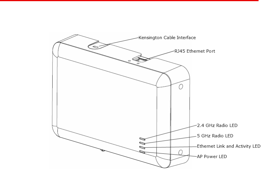
Access Point 8120 front view
The following diagram illustrates the front view of the Access Point 8120.
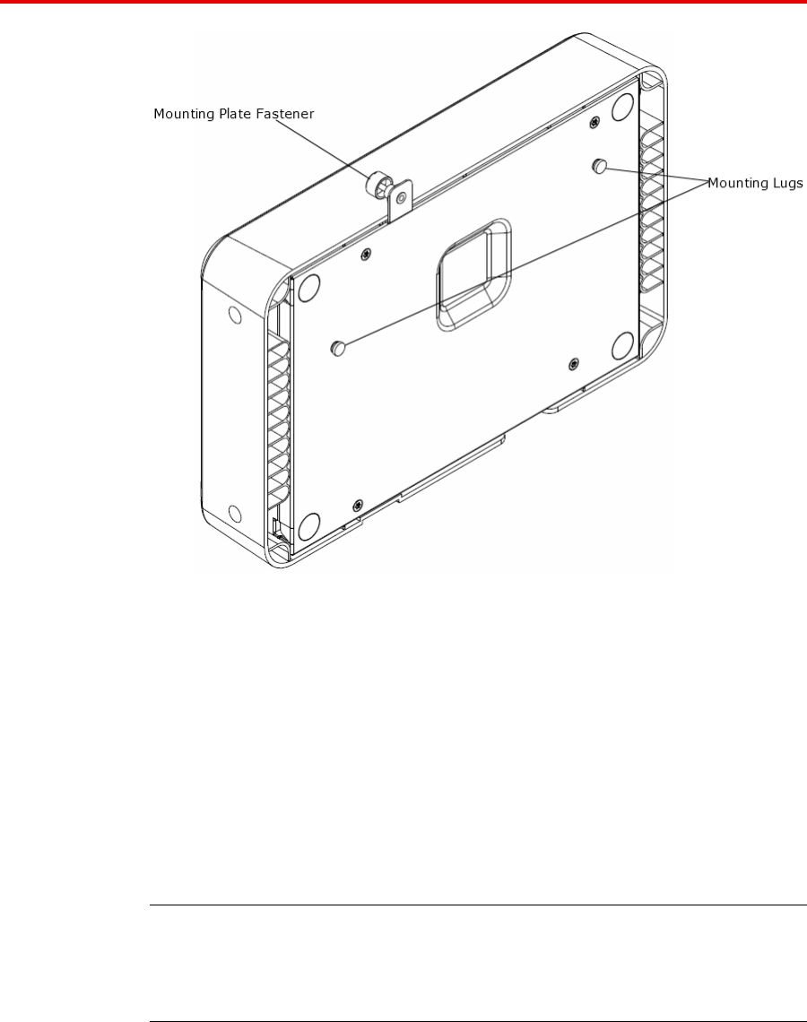
Access Point 8120 rear view
The following diagram illustrates the rear view of the Access Point 8120.
Avaya WLAN 8100
Installation–AP 8120
NN47251-302 01.AD 10 May 2010
.
External hardware features 9
Kensington cable interface
The Access Point 8120 has an interface for attaching a Kensington
security cable. The cable is not included with the access point.
Mounting options
The access point can be mounted on the following types of surfaces:
•Suspended T-bar ceiling
•Junction box
•Solid surface wall or ceiling
Attention: The solid surface mounting option requires CAT-5 cable that
does not have strain relief. Other mounting options can use CAT-5 cable
with or without strain relief.
Avaya WLAN 8100
Installation–AP 8120
NN47251-302 01.AD 10 May 2010
.

10 Installation reference
Status Light-emitting diode (LED)
The AP 8120 has four LEDs that provide status information on the device.
Refer to "Access Point 8120 front view" (page 8) for the location of the
LEDs. The following table describes the different states of the LEDs.
LED Appearance Meaning
Blinking green Associated client is sending or receiving
traffic.
Blinking amber Non-associated client is sending and
receiving traffic.
Alternating green
and amber
The radio is unable to transmit due to
excessive radio interference or the radio
has failed.
2.4 GHz
Unlit The radio is disabled or currently not
experiencing any traffic activity.
Blinking green Associated client is sending or receiving
traffic.
Blinking amber Non-associated client is sending and
receiving traffic.
Alternating green
and amber
The radio is unable to transmit due to
excessive radio interference or the radio
has failed.
5 GHz
Unlit The radio is disabled or currently not
experiencing any traffic activity.
Blinking green The access point is engaged in normal
network activities.
Blinking amber The access point is unable to
communicate with the network.
Ethernet Link
and Activity
Unlit The access point does not have network
connectivity.
Solid green The access point is receiving power.AP Power
Unlit The access point is not receiving power.
Avaya WLAN 8100
Installation–AP 8120
NN47251-302 01.AD 10 May 2010
.

11
.
Installation preparation
Unpacking the access point
The shipping carton for an AP contains the following items:
•one AP
•mounting kit
— one universal mounting bracket (attached to the AP)
— one dual size (15/16 and 5/8 inch) T-bar clamp
— one mounting bracket that attaches to the T-bar clamp and AP
— four adhesive rubber feet
•Avaya WLAN 8100 - Regulatory Information - AP 8120 document
Verify that the items removed from the shipping carton correspond to the
provided list. If an item is missing or damaged, contact Avaya.
Cabling requirements
The AP 8120 access point has one RJ-45 port. This port provides a
10/100/1000BASE-TX Ethernet connection to a Wireless Controller 8180.
This port is used to indirectly connect an access point to a WC 8180
through an intermediate Layer 2 or Layer 3 network.
The access point can receive power and data through the RJ-45 port. Use
a Category 5 (CAT-5) cable with straight-through signaling and standard
RJ-45 connectors to connect to a network device. The AP 8120 supports
802.3af. An Avaya-approved power injectors must be used to provide the
access point with power over the Ethernet cable. The WC 8180 has no
PoE capabilities.
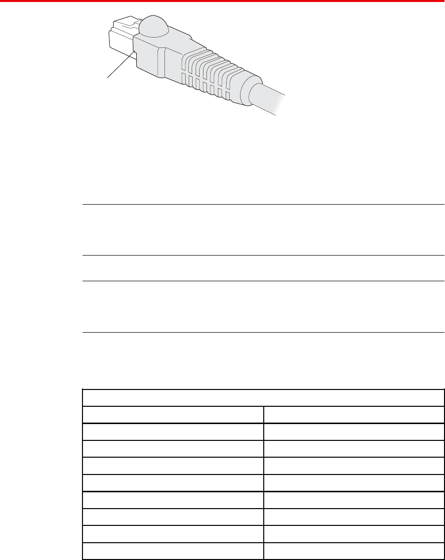
The Ethernet port on the access point cannot accept a CAT-5 cable that
has an uneven sheath as shown below. The RJ-45 connector on the cable
will not seat properly in the receptacle on the access point. Use a CAT-5
cable with an even sheath instead.
Avaya WLAN 8100
Installation–AP 8120
NN47251-302 01.AD 10 May 2010
.
12 Installation preparation
U
neven sheath
8
40-9502-0067
You must operate the access point with a CAT-5 Ethernet cable installed
on the Ethernet port to ensure compliance with the Class B emissions
standards. Failure to comply with this installation requirement can cause
the device to operate in excess of the allowable emissions limits.
Attention: The AP 8120 access point is intended for indoor use only. Do
not install the device or operate it outdoors.
Attention: To reduce the possibility of connection interference caused by
dust, clean the CAT-5 connector pins before inserting a cable into an AP.
The following table lists the pin signals for the 10/100/1000 Ethernet
straight-through wiring. Pins 4, 5, 7, and 8 are used when Avaya Power
over Ethernet (PoE) is enabled on the port.
Wireless Controller 8180
Pin Function
1Bidirectional pair +A
2Bidirectional pair -A
3Bidirectional pair +B
4Bidirectional pair +C
5Bidirectional pair -C
6Bidirectional pair -B
7Bidirectional pair +D
8Bidirectional pair -D
Avaya WLAN 8100
Installation–AP 8120
NN47251-302 01.AD 10 May 2010
.
Radio safety advisories 13
Management software
If you are using the WLAN Management Software (WMS) to plan your
Avaya Mobility System installation, you can create and verify a network
plan for the entire Avaya network installation and generate an AP work
order, before installing any access points.
Network plans and work orders
A network plan and the AP work orders provide the following information
about AP installation and configuration:
•number of APs required for adequate WLAN capacity in each coverage
area
•detailed installation locationfor each AP
•settings for all APs in the WLAN
For information about installing WLAN Management Software , creating
and verifying a network plan, and generating an AP work order, see the
Avaya WLAN 8100 - Planning and Engineering document.
Wireless Controller 8180 recommendation
Avaya recommends that you install and configure the Wireless Controller
8180 before installing an AP. If the switch is already installed and
configured for the access points, you can immediately verify the cable
connection when you plug the cable into the RJ-45 port on the AP.
CAUTION
AP 8120 access points are designed to receive power only
from an 802.3af-compliant source or an Avaya-approved
power injector. Connecting an AP to a Power over Ethernet
(PoE) device that is not approved by Avaya can damage the
equipment.
For more information about connecting an AP to a WC 8180 port, see
Connecting to a Wireless Controller 8180.
Wall installation recommendations
If you plan to install an AP on a partial wall or other vertical surface, orient
the top of the access point (the side with the LEDs) toward the intended
coverage area. The radio antennas transmit through the top of the access
point but not through the bottom (where the bracket is located).
Radio safety advisories
When you enable the AP radios as part of a configuration, the radios can
receive and transmit radio frequency energy as soon as you connect the
AP to the WC 8180, either directly or through the network.
Avaya WLAN 8100
Installation–AP 8120
NN47251-302 01.AD 10 May 2010
.
14 Installation preparation
Radio frequency advisories
Federal Communications Commission (FCC) Docket 96-8 for Spread
Spectrum Transmitters specifies a safety standard for human exposure
to radio frequency electromagnetic energy emitted by FCC-certified
equipment. The Avaya Access Point 8120 product meets the uncontrolled
environmental limits found in OET-65 and ANSI C95.1-1991, if proper
installation procedures are followed. To ensure compliance with these
exposure requirements, you must install this device in such a manner as to
maintain a minimum of 20 cm separation distance between the radiating
elements and all persons.
Additional radio safety advisories
WARNING
Install this device in such a manner as to maintain a minimum of
20 cm (7.9 inches) separation distance between the radiating
elements and all persons. This safety warning conforms with
FCC radio frequency exposure limits.
WARNING
Do not operate the AP near unshielded blasting caps or in an
otherwise explosive environment unless the device has been
modified for such use by qualified personnel.
WARNING
Do not touch or move the AP when the antennas are
transmitting or receiving.
WARNING
Before using a wireless device in a hazardous location, consult
the local codes, national codes, and safety directors of the
location for usage constraints.
Avaya WLAN 8100
Installation–AP 8120
NN47251-302 01.AD 10 May 2010
.
15
.
Access Point 8120 installation
This section contains procedures for the installation of the Access Point
8120.
Mounting a wireless LAN access point on a wall
The mounting bracket is designed to use wall anchors with threaded
section diameters ranging between 3.5mm and 4.5mm. If wall anchors
have threaded diameters greater than 3.5mm, only the two mounting holes
marked ‘A’ may be used. If wall anchors have threaded diameters of less
than 3.5mm, the holes marked ‘A’ and the holes marked ‘B’ may be used.
All wall anchors must have a head diameter of less than 10mm or the wall
mounting bracket cannot be installed over them.
Perform the following procedure to mount a wireless LAN access point on
a wall:
Procedure steps
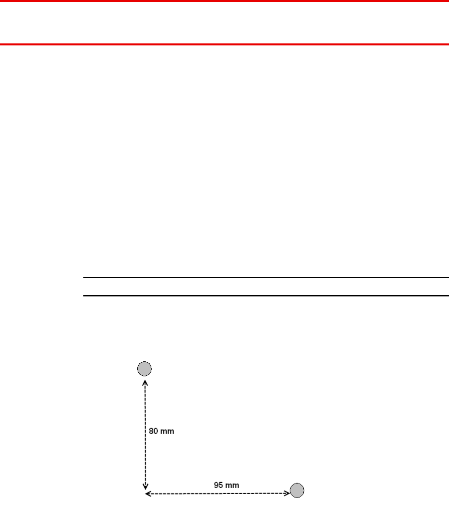
Step Action
1Locate the appropriate position of the wall anchors. The wall
anchors should be 95mm apart horizontally and 80mm apart
vertically.
Avaya WLAN 8100
Installation–AP 8120
NN47251-302 01.AD 10 May 2010
.
16 Access Point 8120 installation
The wall bracket is designed to use a minimum of 2 anchors and
a maximum of 4.
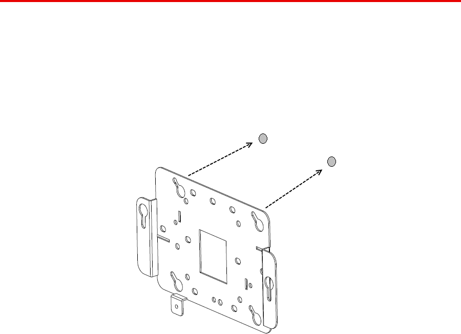
2Install the screws into the wall anchors but do not seat them fully,
leave at least a 2mm gap between the screw head and the wall.
3Slip the wall bracket over the heads of the screws and slide the
bracket to the right as viewed facing the wall.
4Tighten the screws to secure the wall mounting bracket tightly
against the wall.
5Align the mounting tabs on the bottom of the access point sheet
metal enclosure with the vertically oriented keyhole slots in the
mounting bracket.
Avaya WLAN 8100
Installation–AP 8120
NN47251-302 01.AD 10 May 2010
.

Installing an Access Point with a ceiling grid adaptor 17
6Allow the access point to slide down the keyhole slots, making
sure the access point mounting tabs are seated at the bottom
of the slot.
7Secure the access point to the wall mounting bracket and tighten
the thumbscrews.
8Verify that the access point is secured to both the bracket and
to the wall.
--End--
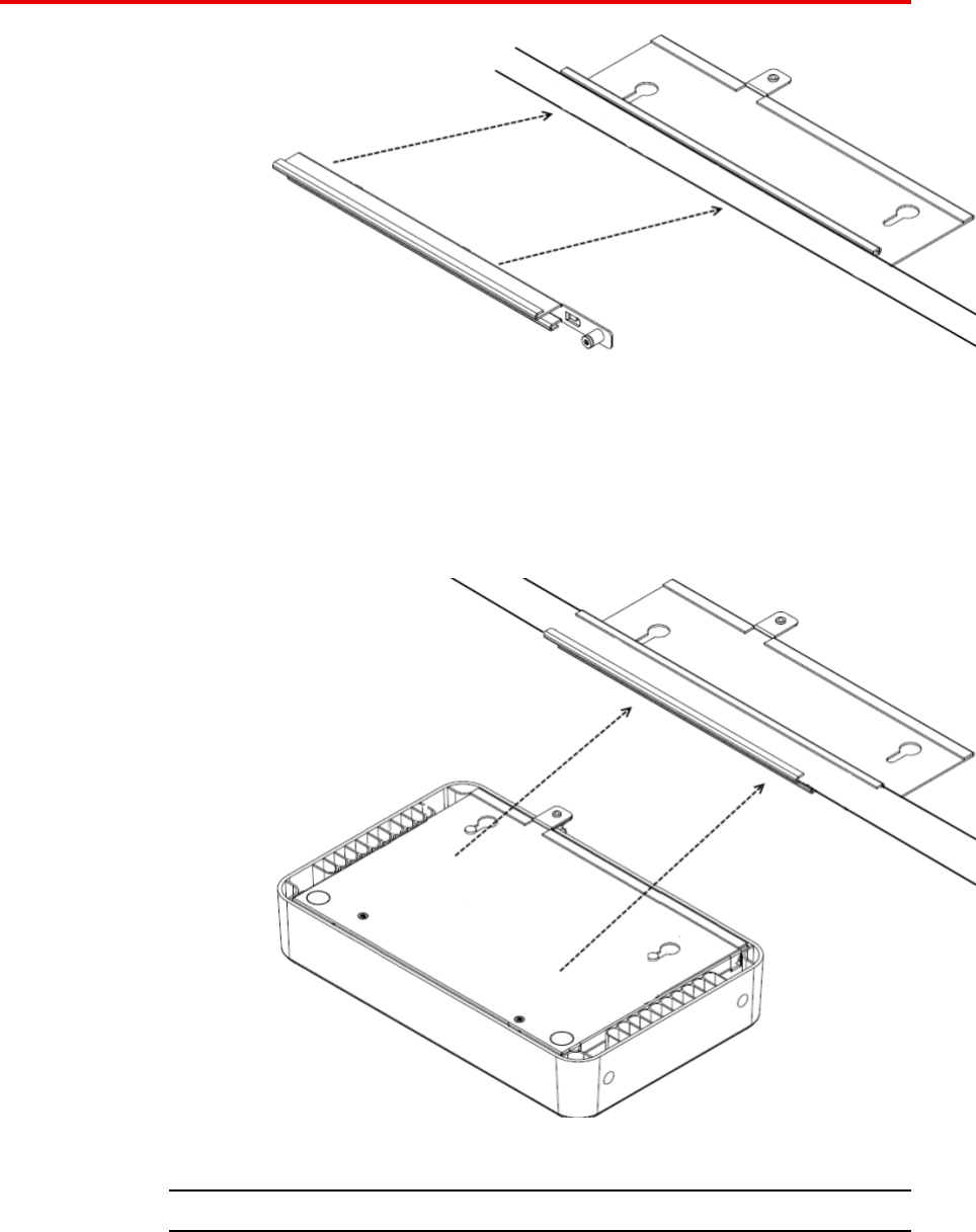
Installing an Access Point with a ceiling grid adaptor
The ceiling grid adaptor comes with two interlocking bracket parts. The
larger bracket includes keyhole shaped slots which mate with tabs on the
under surface of the AP and a threaded hole that mates with the captive
thumbscrew on the AP. The smaller bracket also includes a captive
fastener and it can be oriented with respect to the larger bracket in two
different ways corresponding to narrow or wide ceiling grids.
Perform the following procedure to install the access point with a ceiling
grid adaptor:
Avaya WLAN 8100
Installation–AP 8120
NN47251-302 01.AD 10 May 2010
.
18 Access Point 8120 installation
Procedure steps
Step Action
1Secure a safe work environment. Obtain a ladder that allows
easy access to the ceiling grid system.
2Identify an appropriate location on the ceiling grid where the
ceiling T-bars are safely accessible and where the ceiling tiles
can be temporarily elevated and cleared away from the work
area. The adaptor bracket assembly is intended for use with the
thin section grid runners, not the thicker section runners used to
cross large spans. To provide access for hands and tools, use a
pair of pencils or sticks to hold up the ceiling tiles out of the grid.
Doing this provides easy access for securing the bracket to the
grid.
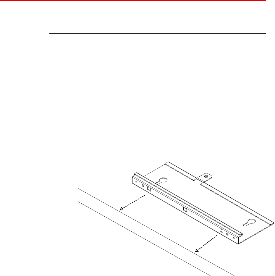
3Mount the larger bracket to the grid. While installing, pay
attention to the width of the grid strip in order to ascertain the
appropriate orientation for the smaller bracket which is installed
next.
4Mount the interlocking small bracket to the large bracket and
clamp the two pieces together on the grid. The smaller bracket
has tabs formed into it which engage slots in the larger tab. This
allows the two parts to slide together and lock to one another.
When this is done, the two brackets effectively clamp themselves
around the ceiling grid. When the two halves of the bracket are
correctly slid together, the captive fastener in the small bracket
should engage threads provided in the larger bracket. Use a
screwdriver to screw down the captive fastener. Securing the
two brackets in this manner is essential to prevent them from
disengaging from one another. Tighten the captive fastener
screw securely.
Avaya WLAN 8100
Installation–AP 8120
NN47251-302 01.AD 10 May 2010
.
Installing an Access Point with a ceiling grid adaptor 19
5Attach the access point to the bracket. Align the access point
securing tabs with the keyhole slots in the ceiling grid bracket
and carefully slide the access point onto the ceiling grid bracket
assembly. If the access point and the bracket assembly are
correctly engaged, it should be possible to engage the access
points captive thumbscrew into the threaded tab provided on the
ceiling grid bracket.
6Make electrical connections and return ceiling tiles.
--End--
Avaya WLAN 8100
Installation–AP 8120
NN47251-302 01.AD 10 May 2010
.

20 Access Point 8120 installation
Avaya WLAN 8100
Installation–AP 8120
NN47251-302 01.AD 10 May 2010
.
21
.
Installation tools and utilities
Installation hardware and tools
The following table lists the mounting hardware and tools required for each
type of installation.
Mounting option Required hardware and
tools Included with the
product
Universal mounting
bracket
Yes
T-bar clamp Yes
Box cutter No
Small screwdriver (3-mm
or 1/8-inch)
No
Ceiling installations
Junction box No
Universal mounting
bracket
Yes
Small screwdriver (3-mm
or 1/8-inch)
No
Wall mounting
#2 Phillips-head
screwdriver
No
Avaya WLAN 8100
Installation–AP 8120
NN47251-302 01.AD 10 May 2010
.

22 Installation tools and utilities
Avaya WLAN 8100
Installation–AP 8120
NN47251-302 01.AD 10 May 2010
.

23
.
Access Point Troubleshooting
After you insert the CAT-5 cable into an AP’s port connector and enable
PoE on the cable, observe the device’s health or link LED to determine the
status of the connection with the WC 8180.
•If the LED is green and is glowing steadily, the AP was booted
successfully by the WC 8180 and is ready for operation.
•If the LED is not steadily glowing green, see the following table.
For descriptions of all the LEDs, see "Status Light-emitting diode (LED)"
(page 10).
Health or
LINK LED
appearance
Diagnosis Remedy
Not solid green AP radio needs to be
enabled.
Enable at least one of the radios.
If the LED is still not solid green,
try the remedy listed in this table
based on the LEDs appearance.
Unlit AP is not receiving
power.
Check the CAT-5 cable
connections.
Do the following:
•Confirm AP health using the
WMS or WC 8180 CLI.
•Verify that an Avaya-approv
ed PoE source is supplying
power to the AP.
Avaya WLAN 8100
Installation–AP 8120
NN47251-302 01.AD 10 May 2010
.

24 Access Point Troubleshooting
Health or
LINK LED
appearance
Diagnosis Remedy
Slowly alterna
ting green and
amber
AP is starting with an
image received from a
WC 8180.
Wait a few seconds for the boot
process to complete. If this LED
appearance persists, enable a
radio or place a radio in sentry
mode.
Solid amber AP is waiting to receive
boot instructions and a
configuration file from a
WC 8180.
Wait a few seconds for the boot
process to begin.
If the LED remains amber, try
the remedies for the other health
LED appearances.
If the LED still remains amber,
ensure the AP is securely
connected to its PoE source and
to the network.
Avaya WLAN 8100
Installation–AP 8120
NN47251-302 01.AD 10 May 2010
.
25
.
Appendix
IEEE 802.11a/b/g Channel Designations:
2400 to 2483.5 MHz band
IEEE Mode 11b/g 11b/g 11b/g 11b/g 11b/g 11b/g 11b/g
Channel number 1234567
Frequency
(GHz)
2.412 2.417 2.422 2.427 2.432 2.437 2.442
IEEE mode 11b/g 11b/g 11b/g 11b/g 11b/g 11b/g 11b/g
Channel number 8 9 10 11 12 13 14
Frequency
(GHz)
2.447 2.452 2.457 2.456 2.467 2.472 2.484
Legend
•11: Channels 1 through 11, inclusive (U.S. based)
•13: Channels 1 through 13, inclusive (EU based)
•14: Channels 1 through 14, inclusive (Japan based)
5.15 to 5.35 GHz bands
IEEE mode 11a 11a 11a 11a 11a 11a 11a 11a
Channel number 36 40 44 48 52 56 60 64
Frequency
(GHz)
5.18
0
5.20
0
5.22
0
5.24
0
5.26
0
5.28
0
5.30
0
5.32
0
5.470 to 5.725 GHz bands
IEEE mode 11a 11a 11a 11a 11a 11a 11a 11a
Channel
Number
100 104 108 112 116 120 124 128
Avaya WLAN 8100
Installation–AP 8120
NN47251-302 01.AD 10 May 2010
.

26 Appendix
Frequency
(GHz)
5.500 5.52
0
5.540 5.56
0
5.580 5.60
0
5.620 5.64
0
IEEE mode 11a 11a 11a
Channel
number
132 136 140
Frequency
(GHz)
5.660 5.68
0
5.700
5.725 to 5.85 GHz bands
IEEE mode 11a 11a 11a 11a 11a
Channel number 149 153 157 161 165
Frequency
(GHz)
5.745 5.765 5.785 5.805 8.825
Legend
•1: Channels 36, 40, 44, 48
•2: Channels 52, 56, 60, 64
•4: Channels 100, 104, 108, 112, 116, 120, 124, 128, 132, 136, 140
•7: Channels 149, 153, 157, 161, 165
•All combinations, such as 1, 2, 7 represent all of the channels listed in
the separate sections of 1, 2 and 7: 36, 40, 44, 48, 52, 56, 60, 64, 149,
153, 157, 161, 165
Avaya WLAN 8100
Installation–AP 8120
NN47251-302 01.AD 10 May 2010
.

27
.
Common antenna terminology
The following glossary includes basic antenna terminology that can help in
the selection and recommendation of a particular antenna.
Omnidirectional (Omni)
Refers to the antenna coverage pattern. An omnidirectional antenna
creates a uniform coverage pattern. Most omnidirectional antennas
are weakest directly above and directly below their endpoints — this
characteristic creates the familiar dual-lobe pattern shown on the E-plane
graphs. Nulls are typically related to the orientation of the dipole/monopole
antenna relative to the horizontal or vertical planes. The lobes grow and
shrink depending upon the ground plane effects and cancellation/addition
of the radiating signal. Omnidirectional antennas are suitable for most
general deployments.
Directional
Refers to the antenna coverage pattern. A directional antenna focuses its
lobe or radiated energy in a particular direction. In general, as the gain of a
directional antenna increases, the radiating beamwidth or lobe decreases.
This design increases the transmitted power and communication distance
in a specific direction at the expense of uniform coverage, as compared
to an omnidirectional antenna. You must aim a directional antenna at the
intended coverage zone.
Gain
Expressed in dBi, indicates the relative increase in radiated power over an
isotropic point radiating source with a reference gain of 1.0.
Each 3 dB increment in power effectively doubles the radiated energy. For
example, an antenna with a gain of 9 dBi increases the transmit power 8
times more than an isotropic point radiating source. For example
12.5 mW = 11 dBm
11 dBm + 9dBi = 20 dBm
20 dBm = 100 mW
100mw/12.5 mW = 8 times more power
Avaya WLAN 8100
Installation–AP 8120
NN47251-302 01.AD 10 May 2010
.

28 Common antenna terminology
E-Plane graph
The elevation plane graph shows the radiated antenna coverage pattern
as a vertical cross section — as if looking directly at the antenna from the
side.
H-Plane graph
The horizontal plane graph shows the radiated antenna coverage pattern
as a horizontal cross section — as if looking directly at the antenna from
above.
Avaya WLAN 8100
Installation–AP 8120
NN47251-302 01.AD 10 May 2010
.