Avaya AP8120 802.11abgn Access Point User Manual NN47251 109 01 02 REGAP8120E
Avaya, Inc. 802.11abgn Access Point NN47251 109 01 02 REGAP8120E
Avaya >
Contents
NN47251-109 01.02 REGAP8120E

Avaya WLAN 8100 Regulatory Information
- WLAN AP 8120 with External Antenna
1.1.0.0
NN47251-109, 01.02
October 2011
© 2011 Avaya Inc.
All Rights Reserved.
Notice
While reasonable efforts have been made to ensure that the
information in this document is complete and accurate at the time of
printing, Avaya assumes no liability for any errors. Avaya reserves the
right to make changes and corrections to the information in this
document without the obligation to notify any person or organization of
such changes.
Documentation disclaimer
“Documentation” means information published by Avaya in varying
mediums which may include product information, operating instructions
and performance specifications that Avaya generally makes available
to users of its products. Documentation does not include marketing
materials. Avaya shall not be responsible for any modifications,
additions, or deletions to the original published version of
documentation unless such modifications, additions, or deletions were
performed by Avaya. End User agrees to indemnify and hold harmless
Avaya, Avaya's agents, servants and employees against all claims,
lawsuits, demands and judgments arising out of, or in connection with,
subsequent modifications, additions or deletions to this documentation,
to the extent made by End User.
Link disclaimer
Avaya is not responsible for the contents or reliability of any linked Web
sites referenced within this site or documentation provided by Avaya.
Avaya is not responsible for the accuracy of any information, statement
or content provided on these sites and does not necessarily endorse
the products, services, or information described or offered within them.
Avaya does not guarantee that these links will work all the time and has
no control over the availability of the linked pages.
Warranty
Avaya provides a limited warranty on its Hardware and Software
(“Product(s)”). Refer to your sales agreement to establish the terms of
the limited warranty. In addition, Avaya’s standard warranty language,
as well as information regarding support for this Product while under
warranty is available to Avaya customers and other parties through the
Avaya Support Web site: http://support.avaya.com. Please note that if
you acquired the Product(s) from an authorized Avaya reseller outside
of the United States and Canada, the warranty is provided to you by
said Avaya reseller and not by Avaya.
Licenses
THE SOFTWARE LICENSE TERMS AVAILABLE ON THE AVAYA
WEBSITE, HTTP://SUPPORT.AVAYA.COM/LICENSEINFO/ ARE
APPLICABLE TO ANYONE WHO DOWNLOADS, USES AND/OR
INSTALLS AVAYA SOFTWARE, PURCHASED FROM AVAYA INC.,
ANY AVAYA AFFILIATE, OR AN AUTHORIZED AVAYA RESELLER
(AS APPLICABLE) UNDER A COMMERCIAL AGREEMENT WITH
AVAYA OR AN AUTHORIZED AVAYA RESELLER. UNLESS
OTHERWISE AGREED TO BY AVAYA IN WRITING, AVAYA DOES
NOT EXTEND THIS LICENSE IF THE SOFTWARE WAS OBTAINED
FROM ANYONE OTHER THAN AVAYA, AN AVAYA AFFILIATE OR AN
AVAYA AUTHORIZED RESELLER; AVAYA RESERVES THE RIGHT
TO TAKE LEGAL ACTION AGAINST YOU AND ANYONE ELSE
USING OR SELLING THE SOFTWARE WITHOUT A LICENSE. BY
INSTALLING, DOWNLOADING OR USING THE SOFTWARE, OR
AUTHORIZING OTHERS TO DO SO, YOU, ON BEHALF OF
YOURSELF AND THE ENTITY FOR WHOM YOU ARE INSTALLING,
DOWNLOADING OR USING THE SOFTWARE (HEREINAFTER
REFERRED TO INTERCHANGEABLY AS “YOU” AND “END USER”),
AGREE TO THESE TERMS AND CONDITIONS AND CREATE A
BINDING CONTRACT BETWEEN YOU AND AVAYA INC. OR THE
APPLICABLE AVAYA AFFILIATE ( “AVAYA”).
Copyright
Except where expressly stated otherwise, no use should be made of
materials on this site, the Documentation, Software, or Hardware
provided by Avaya. All content on this site, the documentation and the
Product provided by Avaya including the selection, arrangement and
design of the content is owned either by Avaya or its licensors and is
protected by copyright and other intellectual property laws including the
sui generis rights relating to the protection of databases. You may not
modify, copy, reproduce, republish, upload, post, transmit or distribute
in any way any content, in whole or in part, including any code and
software unless expressly authorized by Avaya. Unauthorized
reproduction, transmission, dissemination, storage, and or use without
the express written consent of Avaya can be a criminal, as well as a
civil offense under the applicable law.
Third-party components
Certain software programs or portions thereof included in the Product
may contain software distributed under third party agreements (“Third
Party Components”), which may contain terms that expand or limit
rights to use certain portions of the Product (“Third Party Terms”).
Information regarding distributed Linux OS source code (for those
Products that have distributed the Linux OS source code), and
identifying the copyright holders of the Third Party Components and the
Third Party Terms that apply to them is available on the Avaya Support
Web site: http://support.avaya.com/Copyright.
Trademarks
The trademarks, logos and service marks (“Marks”) displayed in this
site, the Documentation and Product(s) provided by Avaya are the
registered or unregistered Marks of Avaya, its affiliates, or other third
parties. Users are not permitted to use such Marks without prior written
consent from Avaya or such third party which may own the Mark.
Nothing contained in this site, the Documentation and Product(s)
should be construed as granting, by implication, estoppel, or otherwise,
any license or right in and to the Marks without the express written
permission of Avaya or the applicable third party.
Avaya is a registered trademark of Avaya Inc.
All non-Avaya trademarks are the property of their respective owners,
and “Linux” is a registered trademark of Linus Torvalds.
Downloading Documentation
For the most current versions of Documentation, see the Avaya
Support Web site: http://support.avaya.com.
Contact Avaya Support
Avaya provides a telephone number for you to use to report problems
or to ask questions about your Product. The support telephone number
is 1-800-242-2121 in the United States. For additional support
telephone numbers, see the Avaya Web site: http://support.avaya.com.
2 Avaya WLAN 8100 Regulatory Information - WLAN AP 8120 with External Antenna October 2011
Comments? infodev@avaya.com
Contents
Chapter 1: Regulatory Compliance Statements............................................................... 5
Federal Communications Commission (FCC) Compliance Notices.......................................................... 5
Class B Interference Statement................................................................................................................ 5
Class B Equipment (Residential Use) (Korean)........................................................................................ 6
FCC Caution............................................................................................................................................. 6
RF Radiation Exposure and Hazard Statement........................................................................................ 6
Non-Modification Statement...................................................................................................................... 7
Deployment Statement.............................................................................................................................. 7
Dynamic Frequency Selection (DFS) in the 5.0 GHz UNII bands............................................................. 7
Canadian IC Statements........................................................................................................................... 7
European Union and European Free Trade Association (EFTA) Regulatory Compliance........................ 8
Declaration of Conformity.......................................................................................................................... 8
European Community Declaration of Conformity...................................................................................... 9
Countries of Operation and Restrictions of Use in the European Community.......................................... 11
Operation Using the 2.400 to 2.4835 GHz Channels in the European Community.................................. 11
Operation Using the 5.15 to 5.25 GHz, 5.25 to 5.35 GHz, and 5.470 to 5.725 GHz Channels in the
European Community............................................................................................................................... 12
Dynamic Frequency Selection (DFS)........................................................................................................ 12
Transmit Power Control............................................................................................................................ 13
Antenna Statement................................................................................................................................... 13
Chapter 2: Devices with detachable antennas................................................................. 15
Chapter 3: English.............................................................................................................. 17
Cable requirements................................................................................................................................... 17
Mounting the WLAN AP 8120 with External Antenna on a wall................................................................ 17
Installing the WLAN AP 8120 with External Antenna to the ceiling.......................................................... 21
Safety Messages....................................................................................................................................... 26
Chapter 4: Deutsch............................................................................................................. 27
Kabelanschlüsse....................................................................................................................................... 27
Wandmontage des WLAN AP 8120 mit externer Antenne....................................................................... 27
Deckenmontage des WLAN AP 8120 mit externer Antenne.................................................................... 31
Sicherheitshinweise.................................................................................................................................. 36
Chapter 5: Español............................................................................................................. 37
Requisitos de cableado............................................................................................................................. 37
Cómo montar la WLAN AP 8120 con antena externa en una pared........................................................ 37
Instalación de la WLAN AP 8120 con la antena externa en el techo........................................................ 41
Advertencias de seguridad....................................................................................................................... 45
Chapter 6: Français............................................................................................................. 47
Configuration requise pour les câbles....................................................................................................... 47
Installation murale du point d'accès 8120 WLAN avec antenne externe.................................................. 47
Installation du point d'accès 8120 WLAN avec antenne externe au plafond............................................ 51
Messages de sécurité............................................................................................................................... 55
Chapter 7: Português do Brasil......................................................................................... 57
Requisitos de cabo.................................................................................................................................... 57
Montando o WLAN AP 8120 com antena externa em uma parede.......................................................... 57
Avaya WLAN 8100 Regulatory Information - WLAN AP 8120 with External Antenna October 2011 3
Instalando o WLAN AP 8120 com antena externa no teto....................................................................... 61
Mensagens de segurança......................................................................................................................... 65
Chapter 8: Simplified Chinese........................................................................................... 67
Chinese..................................................................................................................................................... 68
4 Avaya WLAN 8100 Regulatory Information - WLAN AP 8120 with External Antenna October 2011
Chapter 1: Regulatory Compliance
Statements
The Avaya WLAN 8100 product line consists of the following models:
• WLAN AP 8120
• WLAN AP 8120 with External Antenna
Warning:
The AP8120 and the AP8120 with External Antenna are both designed for indoor use only and must
not be installed outdoors.
Warning:
The AP8120 with External Antenna must be installed by a professional installer.
This section contains regulatory compliance statements for the WLAN AP 8120 with External Antenna
model.
Federal Communications Commission (FCC) Compliance
Notices
This section includes the following FCC statements for the WLAN AP 8120 with External
Antenna access point:
• FCC ID:
• Class B Interference Statement
• RF Radiation Exposure and Hazard Warning
• Non-Modification Statement
• Deployment Statement
Class B Interference Statement
This equipment has been tested and found to comply with the limits for a Class B digital device,
pursuant to Part 15 of the FCC Rules. These limits are designed to provide reasonable
protection against harmful interference in a residential installation. This equipment generates,
Avaya WLAN 8100 Regulatory Information - WLAN AP 8120 with External Antenna October 2011 5
uses, and can radiate radio frequency energy and, if not installed and used in accordance with
the instructions, may cause harmful interference to radio communications. However, there is
no guarantee that interference will not occur in a particular installation. If this equipment does
cause harmful interference to radio or television reception, which can be determined by turning
the equipment off and on, the user is encouraged to try to correct the interference by one or
more of the following measures:
• Reorient or relocate the receiving antenna.
• Increase the separation between the equipment and receiver.
•Connect the equipment into an outlet on a circuit different from that to which the receiver
is connected.
• Consult the dealer or an experienced radio/TV technician for help.
Class B Equipment (Residential Use) (Korean)
FCC Caution
This device complies with Part 15 of the FCC Rules. Operation is subject to the following two
conditions: (1) This device may not cause harmful interference, and (2) this device must accept
any interference received, including interference that may cause undesired operation.
RF Radiation Exposure and Hazard Statement
To ensure compliance with FCC RF exposure requirements, this device must be installed in a
location such that the antenna of the device will be greater than 24.9 cm (9.8 in.) away from
all persons. Using higher gain antennas and types of antennas not covered under the FCC
certification of this product is not allowed. Installers of the radio and end users of the product
must adhere to the installation instructions provided in this manual.
This transmitter must not be co-located or operating in conjunction with any other antenna or
transmitter.
Regulatory Compliance Statements
6 Avaya WLAN 8100 Regulatory Information - WLAN AP 8120 with External Antenna October 2011
Comments? infodev@avaya.com

Non-Modification Statement
Use only the supplied internal antenna. Unauthorized antennas, modifications, or attachments
could damage the WLAN AP 8120 with External Antenna and violate FCC regulations. Any
changes or modifications not expressly approved by the party responsible for compliance could
void the user's authority to operate this equipment.
Deployment Statement
This product is certified for indoor deployment only. Do not install or use this product
outdoors.
Dynamic Frequency Selection (DFS) in the 5.0 GHz UNII
bands
The WLAN AP 8120 with External Antenna access point has been prohibited, via software,
from operating in the 5250 to 5350 MHz and 5470 to 5725 MHz frequency bands for the US
and Canada because it is in the process of certification (has not yet been certified), to meet
the DFS requirements as outlined in the rules of the FCC for Part 15, Subpart E that came into
force on July 20, 2007.
Canadian IC Statements
This device complies with Industry Canada licence-exempt RSS standard(s). Operation is
subject to the following two conditions: (1) this device may not cause interference, and (2) this
device must accept any interference, including interference that may cause undesired
operation of the device.
Le présent appareil est conforme aux CNR d'Industrie Canada applicables aux appareils radio
exempts de licence. L'exploitation est autorisée aux deux conditions suivantes : (1) l'appareil
ne doit pas produire de brouillage, et (2) l'utilisateur de l'appareil doit accepter tout brouillage
radioélectrique subi, même si le brouillage est susceptible d'en compromettre le
fonctionnement.
The device for operation in the band 5150-5250 MHz is only for indoor use to reduce the
potential for harmful interference to co-channel mobile satellite systems.
Non-Modification Statement
Avaya WLAN 8100 Regulatory Information - WLAN AP 8120 with External Antenna October 2011 7
Les dispositifs fonctionnant dans la bande 5150-5250 MHz sont réservés uniquement pour
une utilisation à l’intérieur afin de réduire les risques de brouillage préjudiciable aux systèmes
de satellites mobiles utilisant les mêmes canaux.
Be advised that high-power radars are allocated as primary users (i.e. priority users) of the
bands 5250-5350 MHz and 5650-5850 MHz and that these radars could cause interference
and/or damage to LE-LAN devices.
Les utilisateurs de radars de haute puissance sont désignés utilisateurs principaux (c.-à-d.,
qu’ils ont la priorité) pour les bandes 5250-5350 MHz et 5650-5850 MHz et que ces radars
pourraient causer du brouillage et/ou des dommages aux dispositifs LAN-EL.
European Union and European Free Trade Association
(EFTA) Regulatory Compliance
This equipment may be operated in the countries that comprise the member countries of the
European Union and the European Free Trade Association. These countries, listed in the
following paragraph, are referred to as The European Community throughout this document:
AUSTRIA, BELGIUM, BULGARIA, CYPRUS, CZECH REPUBLIC, DENMARK, ESTONIA,
FINLAND, FRANCE, GERMANY, GREECE, HUNGARY, IRELAND, ITALY, LATVIA,
LITHUANIA, LUXEMBOURG, MALTA, NETHERLANDS, POLAND, PORTUGAL, ROMANIA,
SLOVAKIA, SLOVENIA, SPAIN, SWEDEN, UNITED KINGDOM, ICELAND, LICHTENSTEIN,
NORWAY, SWITZERLAND.
The WLAN AP 8120-E access point communicates with an Avaya WLAN 8100 Wireless
Controller using a standard CAT-5 (Category 5) or higher 1000 Mbps twisted pair Ethernet
cable to provide wireless local area networking (WLAN) capabilities. The WLAN AP 8120 with
External Antenna access point includes two 802.11a+n, b/g+n radios.
Declaration of Conformity
Marking by this symbol
indicates compliance with the Essential Requirements of the R&TTE Directive of the European
Union (1999/5/EC). This equipment meets the following conformance standards:
Safety: EN 60950-1:2001 + A11:2004
EMC: EN 55022:2006, EN 55024:1998 + A1:2001 + A2:2003, EN 301-489-1 v1.6.1, EN
301-489-17 v1.2.1, CISPR22:2005, CISPR24
Regulatory Compliance Statements
8 Avaya WLAN 8100 Regulatory Information - WLAN AP 8120 with External Antenna October 2011
Comments? infodev@avaya.com

Including: EN 61000-3-2, -3-3, -4-2, -4-3, -4-4, -4-5, -4-6 and -4-11. The product is also licensed
as required for additional country specific standards as required for the International
Marketplace.
Radio: EN 300-328 v.1.7.1 (2006-10) & EN 301-893 v.1.5.1 (2008-12)
DEVIATION: The WLAN AP 8120 with External Antenna access point was tested to and are
compliant with all of the technical specifications of EN 301-893 v1.5.1 for operation in the 5.0
GHz bands, except the DFS requirements in the 5600 – 5650 MHz band.
IEEE 802.11a operation in the 5250 to 5350 MHz and 5470 to 5725 MHz frequency bands is
governed by ETSI EN 301-893 v1.5.1 and the R&TTE Directive 1999/5/EC. Effective July 1,
2008, EN 301-893 v1.5.1 was updated to require compliance with 0.8 μsecond pulse widths
and staggered PRF’s in the 5470 – 5725 MHz band. The WLAN AP 8120 with External Antenna
access point meets compliance with these new mandates by disabling operation, via software,
on channels 120, 124, 128 and 132 in the 5600 to 5650 MHz frequency band because it cannot
meet the 0.8 μsecond pulse width and staggered PRF DFS requirements as outlined in the
updated EN 301-893 v1.5.1 standard.
Electromagnetic compatibility and Radio spectrum Matters (ERM); Wideband transmission
systems; Data transmission equipment operating in the 2,4 GHz ISM band and using wide
band modulation techniques and Broadband Radio Access Networks (BRAN); 5 GHz high
performance RLAN. Certifications are harmonized to the EN standards covering essential
requirements under article 3.2 of the R&TTE Directive.
SAR: EN 50385:2002
European Community Declaration of Conformity
WLAN Radio Model, WLAN AP 8120 with External Antenna, as stated in the following
Declarations of Conformity, represents all models in the WLAN AP 8120 with External Antenna
as listed above.
Bulgaria български
С това, avayal обявява, че този модел на радио на WLAN Радио Модел
AP 8120-E, е със съгласие с съществените изисквания и други важни
условия на директива 1999/5 на европейски съюз
Czech
Republic Èesky
Avaya tímto prohlašuje, že tento WLAN Rádio Model, WLAN AP 8120-E, je
ve shodì se základními požadavky a dalšími pøíslušnými ustanoveními
smìrnice 1999/5/ES.
Denmark Dansk
Undertegnede Avayaerklærer herved, at følgende udstyr WLAN Radio Model,
WLAN AP 8120-E, overholder de væsentlige krav og øvrige relevante krav i
direktiv 1999/5/EF.
English English
European Community Declaration of Conformity
Avaya WLAN 8100 Regulatory Information - WLAN AP 8120 with External Antenna October 2011 9
Hereby, Avaya declares that this WLAN Radio Model, WLAN AP 8120 with
External Antenna, is in compliance with the essential requirements and other
relevant provisions of Directive 1999/5/EC.
Estonia Eesti
Käesolevaga kinnitab Avayaseadme WLAN Radio Model, WLAN AP 8120-E,
vastavust direktiivi 1999/5/EÜ põhinõuetele ja nimetatud direktiivist
tulenevatele teistele asjakohastele sätetele.
Finland Suomi
Avayavakuuttaa täten että WLAN Radio Esikuvallinen, WLAN AP 8120-E,
tyyppinen laite on direktiivin 1999/5/EY oleellisten vaatimusten ja sitä
koskevien direktiivin muiden ehtojen mukainen.
France Français
Par la présente Avaya déclare que l'appareil Model Par radio, WLAN AP 8120-
E de WLAN, est conforme aux exigencies essentielles et aux autres
dispositions pertinentes de la directive 1999/5/CE.
Germany Deutsch
Hiermit erklärt Avaya., dass sich das Gerät WLAN Radiomodell, WLAN AP
8120-E, in Übereinstimmung mit den grundlegenden Anforderungen und den
übrigen einschlägigen Bestimmungen der Richtlinie 1999/5/EG befindet.
Greece ΕΛΛΗΝΙΚΗ
Hungary Magyar
Alulírott, Avayanyilatkozom, hogy a WLAN Rádió Minta, WLAN AP 8120-E,
megfelel a vonatkozó alapvetõ követelményeknek és az 1999/5/EC irányelv
egyéb elõírásainak.
Italy Italiano
Con la presente Avayadichiara che questo Modello Radiofonico WLAN, AP
8120-E di WLAN, è conforme ai requisiti essenziali ed alle alter disposizioni
pertinenti stabilite dalla direttiva 1999/5/CE.
Latvia Latviski
Ar šo Avayadeklarç, ka WLAN Radio Model, WLAN AP 8120-E, atbilst
Direktîvas 1999/5/EK bûtiskajâm prasîbâm un citiem ar to saistîtajiem
noteikumiem.
Lithuania Lietuviø
Šiuo Avayadeklaruoja, kad šis WLAN Radio Model, WLAN AP 8120-E, atitinka
esminius reikalavimus ir kitas 1999/5/EB Direktyvos nuostatas.
Malta Malti
Hawnhekk, Avaya., jiddikjara li dan WLAN Radio, Model WLAN AP 8120-E,
jikkonforma mal-tiijiet essenzjali u ma provvedimenti orajn relevanti li hemm
fid-Dirrettiva 1999/5/EC.
Netherland
sNetherlands
Regulatory Compliance Statements
10 Avaya WLAN 8100 Regulatory Information - WLAN AP 8120 with External Antenna October 2011
Comments? infodev@avaya.com

Hierbij verklaart Avayadat het toestel WLAN Radiomodel, WLAN AP 8120-E,
in overeenstemming is met de essentiële eisen en de andere relevante
bepalingen van richtlijn 1999/5/EG.
Poland Polski
Niniejszym Avayaooewiadcza, ¿e WLAN Radio Model, WLAN AP 8120-E, jest
zgodny z zasadniczymi wymogami oraz pozosta³ymi stosownymi
postanowieniami Dyrektywy 1999/5/EC.
Portugal Português
Avaya declara que este Modelo De rádio WLAN, AP 8120-E de WLAN, está
conforme com os requisitos essenciais e outras disposições da Directiva
1999/5/CE.
Romania Român
Astfel, Avaya declarã acel acest WLAN Radio Model, WLAN AP 8120-E, este
în conformitate cu cerinþele necesare ºi proviziile alte semnificative de
Directive 1999 5 EC.
Slovakia Slovensky
Avaya týmto vyhlasuje, že WLAN Radio Model, WLAN AP 8120-E spåòa
základné požiadavky a všetky príslušné ustanovenia Smernice 1999/5/ES.
Slovenia Slovensko
Avaya izjavlja, da je ta WLAN Radio Model, WLAN AP 8120-E, v skladu z
bistvenimi zahtevami in ostalimi relevantnimi doloèili directive 1999/5/ES.
Spain Español
Por medio de la presente Avaya declara que el Modelo De radio, WLAN AP
8120-E de WLAN, cumple con los requisitos esenciales y cualesquiera otras
disposiciones aplicables o exigibles de la Directiva 1999/5/CE.
Sweden Svenska
Härmed intygar Avaya elatt denna WLAN Radiotelegrafera till Modell, WLAN
AP 8120-E, står I överensstämmelse med de väsentliga egenskapskrav och
övriga relevanta bestämmelser som framgår av direktiv 1999/5/EG.
Countries of Operation and Restrictions of Use in the
European Community
Operation Using the 2.400 to 2.4835 GHz Channels in the
European Community
The professional installer should use the configuration utility provided with this product to verify
the current channel of operation, the expected transmit power level, and to confirm that the
Countries of Operation and Restrictions of Use in the European Community
Avaya WLAN 8100 Regulatory Information - WLAN AP 8120 with External Antenna October 2011 11

device is operating in conformance with the spectrum usage rules for the selected European
Community country. If operation is occurring outside of the allowable channels as indicated in
this guide, then operation of the product must cease immediately and the installer must consult
with the local technical support staff responsible for the wireless network.
This device is intended to be operated in all countries of the European Community. Additional
restrictions of use for the WLAN AP 8120 with External Antenna access point within the
European Community countries in the 2.400 to 2.4835 GHz band are listed below.
• The frequencies associated with channels 1 to 13 in the 2.400 to 2.4835 GHz band are
allowed to be used either indoors or outdoors in all countries of the European Community,
except where noted below.
• In France, the following operation is permitted:
Indoor operation is permitted in the 2.400 to 2.4835 GHz band on channels 1 to 13 at
a maximum EIRP of 100 mW (20 dBm).
The WLAN AP 8120 with External Antenna access point is guaranteed to meet this limit by
automatically adjusting the transmit power level through the operating software.
Operation Using the 5.15 to 5.25 GHz, 5.25 to 5.35 GHz, and
5.470 to 5.725 GHz Channels in the European Community
To remain in conformance with European National spectrum usage laws, follow the channel
limitations associated with the 5 GHz bands as specified in this document. The professional
installer should verify the current channel of operation and the expected transmit power level
of the WLAN AP 8120 with External Antenna access point to confirm that the device is
operating in conformance with the spectrum usage rules for the European Community country
where the unit is being installed. If operation is occurring outside of the allowable frequencies
or above the power levels, as indicated in this guide, then operation of the product must cease
immediately and the installer must consult with the local technical support staff responsible for
the wireless network.
This device is intended to be operated in all countries of the European Community. Additional
restrictions of use for the WLAN AP 8120 with External Antenna access points within the
European Community countries in the 5.15 to 5.25 GHz, 5.25 to 5.35 GHz, and 5.470 to 5.725
GHz bands are listed below.
This device is restricted to indoor use only when operated in the European Community using
the 5.15-5.25 GHz and 5.25-5.35 GHz bands, which includes channels 36, 40, 44, 48, 52,
56, 60 & 64. • The 5 GHz Turbo Mode feature is not allowed for operation in any European
Community country.
Dynamic Frequency Selection (DFS)
The WLAN AP 8120 with External Antenna access point implements a DFS feature in
accordance with the limits in EN 301-893 v1.5.1, Section 4.7 and Annex D, Tables D.1, D.2 &
Regulatory Compliance Statements
12 Avaya WLAN 8100 Regulatory Information - WLAN AP 8120 with External Antenna October 2011
Comments? infodev@avaya.com

D.4 for a device operating in the mode defined as “Master”. Section 4.7 and Tables 5 of this
document define the requirements prior to using a channel and during normal operation for a
Master device (i.e., Interference Detection Threshold, Channel Availability Check Time,
Uniform Spreading, Channel Closing Transmission Time and Channel Move Time). This
product qualifies for this category since the maximum achievable transmit power is greater
than 23 dBm per the requirements of Table D.2 in Annex D of the standard.
IEEE 802.11a operation in the 5250 to 5350 MHz and 5470 to 5725 MHz frequency bands is
governed by ETSI EN 301-893 v1.5.1 and the R&TTE Directive 1999/5/EC. Effective July 1,
2008, EN 301-893 v1.5.1 was updated to require compliance with 0.8 μsecond pulse widths
and staggered PRF’s in the 5470 – 5725 MHz band. The WLAN AP 8120 with External Antenna
access point meets compliance with these new mandates by disabling operation, via software,
on channels 120, 124, 128 and 132 in the 5600 to 5650 MHz frequency band because it cannot
meet the 0.8 μsecond pulse width and staggered PRF DFS requirements as outlined in the
updated EN 301-893 v1.5.1 standard.
Transmit Power Control
European Regulatory requirements specify that wireless devices must employ Transmit Power
Control (TPC) to reduce the potential for interference to other communication systems
operating in the 5 GHz frequency bands. This device includes a provision for adjustment of
Transmit Power in accordance with the limits in EN 301-893 v1.5.1, Sections 4.4.2.1 and
4.4.2.2.
Antenna Statement
Intentional radiators, such as the WLAN AP 8120 with External Antenna access point, are not
intended to be operated with any antenna(s) other than those furnished by Avaya. An
intentional radiator may only be operated with the antenna(s) with which it is authorized.
Use of an antenna not specifically authorized by Avaya may not comply with local regulatory
requirements with respect to radiated emission limits and may result in illegal operation of the
product. The installer of the wireless system and associated antenna is required to ensure that
only those antennas specifically approved by Avaya are deployed with the intentional
radiator.
Be sure to associate the appropriate antenna model number and localized regulatory region
when selecting the Avaya authorized antenna(s).
Transmit Power Control
Avaya WLAN 8100 Regulatory Information - WLAN AP 8120 with External Antenna October 2011 13

Chapter 2: Devices with detachable
antennas
Under Industry Canada regulations, this radio transmitter may only operate using an antenna of a type
and maximum (or lesser) gain approved for the transmitter by Industry Canada. To reduce potential radio
interference to other users, the antenna type and its gain should be so chosen that the equivalent
isotropically radiated power (e.i.r.p.) is not more than that necessary for successful communication.
Conformément à la réglementation d'Industrie Canada, le présent émetteur radio peut fonctionner avec
une antenne d'un type et d'un gain maximal (ou inférieur) approuvé pour l'émetteur par Industrie Canada.
Dans le but de réduire les risques de brouillage radioélectrique à l'intention des autres utilisateurs, il faut
choisir le type d'antenne et son gain de sorte que la puissance isotrope rayonnée équivalente (p.i.r.e.) ne
dépasse pas l'intensité nécessaire à l'établissement d'une communication satisfaisante.
This radio transmitter WLAN AP 8120 with External Antenna has been approved by Industry Canada to
operate with the antenna types listed below with the maximum permissible gain and required antenna
impedance for each antenna type indicated. Antenna types not included in this list, having a gain greater
than the maximum gain indicated for that type, are strictly prohibited for use with this device.
Le présent émetteur radio WLAN AP 8120-E a été approuvé par Industrie Canada pour fonctionner avec
les types d'antenne énumérés ci-dessous et ayant un gain admissible maximal et l'impédance requise
pour chaque type d'antenne. Les types d'antenne non inclus dans cette liste, ou dont le gain est supérieur
au gain maximal indiqué, sont strictement interdits pour l'exploitation de l'émetteur.
Antenna types approved for use with the transmitter:
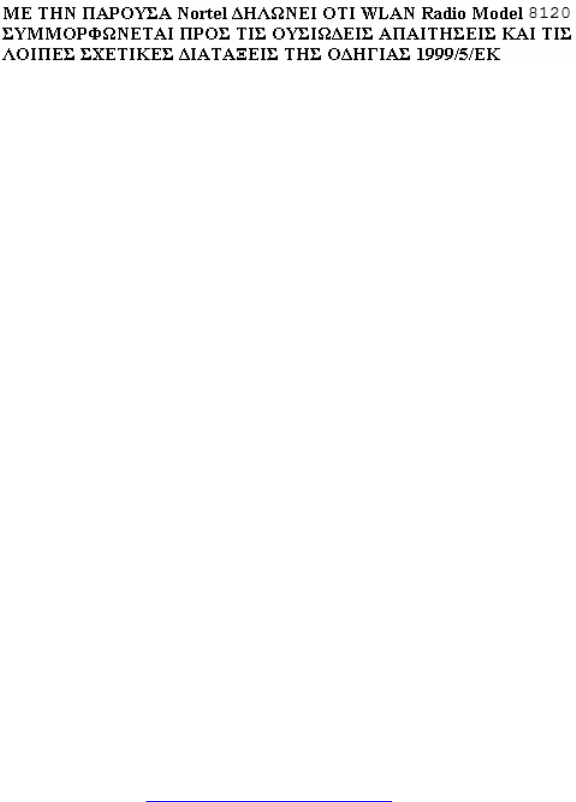
1. Laird Technologies S24517PT36RSM:
Maximum permissible antenna gain <11 dBi
Impedance 50 ohms
Product code: WL81AT180E6
2. TYCO Electronics 2118235-1:
Maximum permissible antenna gain <6 dBi
Impedance 50 ohms
Product code: WL81AT070E6
The following figure shows the Laird Technologies antenna supported by the WLAN AP 8120 with External
Antenna.
Laird antenna
Avaya WLAN 8100 Regulatory Information - WLAN AP 8120 with External Antenna October 2011 15
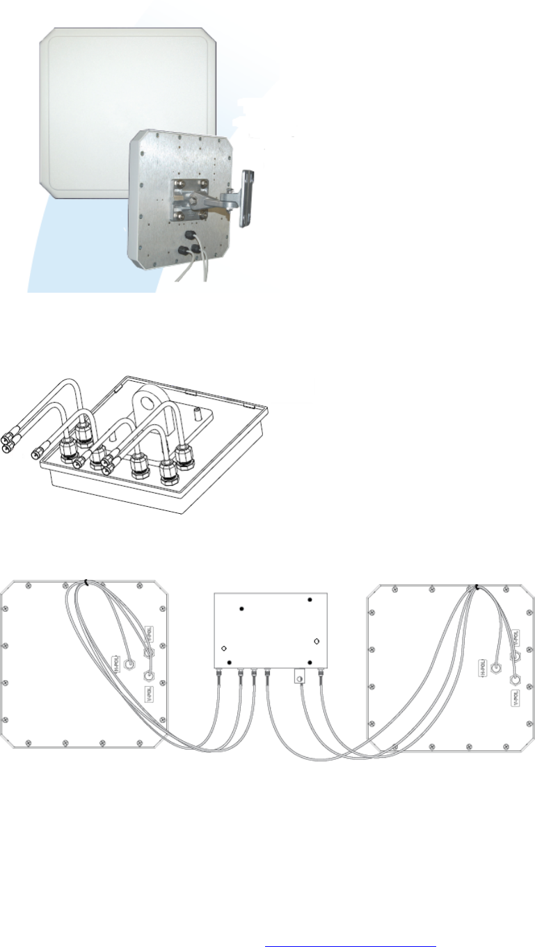
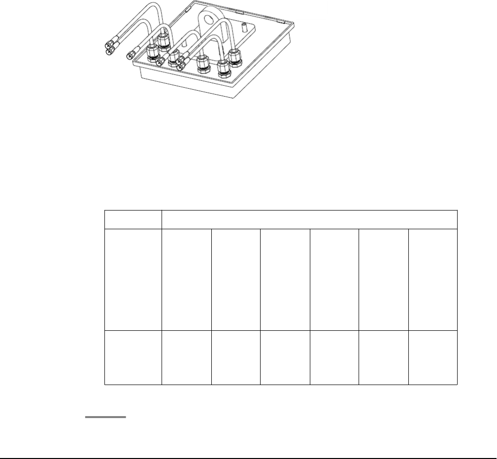
The following figure shows the TYCO Electronics antenna supported by the WLAN AP 8120 with External
Antenna.
TYCO antenna with bracket mount and antenna cables
The following figure shows the WLAN AP 8120 with External Antenna with attached antennas.
WLAN AP 8120 with External Antenna attached to Laird antennas
Devices with detachable antennas
16 Avaya WLAN 8100 Regulatory Information - WLAN AP 8120 with External Antenna October 2011
Comments? infodev@avaya.com
Chapter 3: English
Using the following procedures and information when installing the Avaya WLAN AP 8120 with External
Antenna access points.
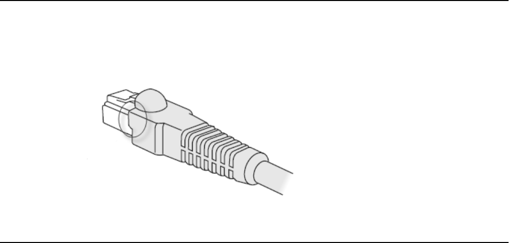
Cable requirements
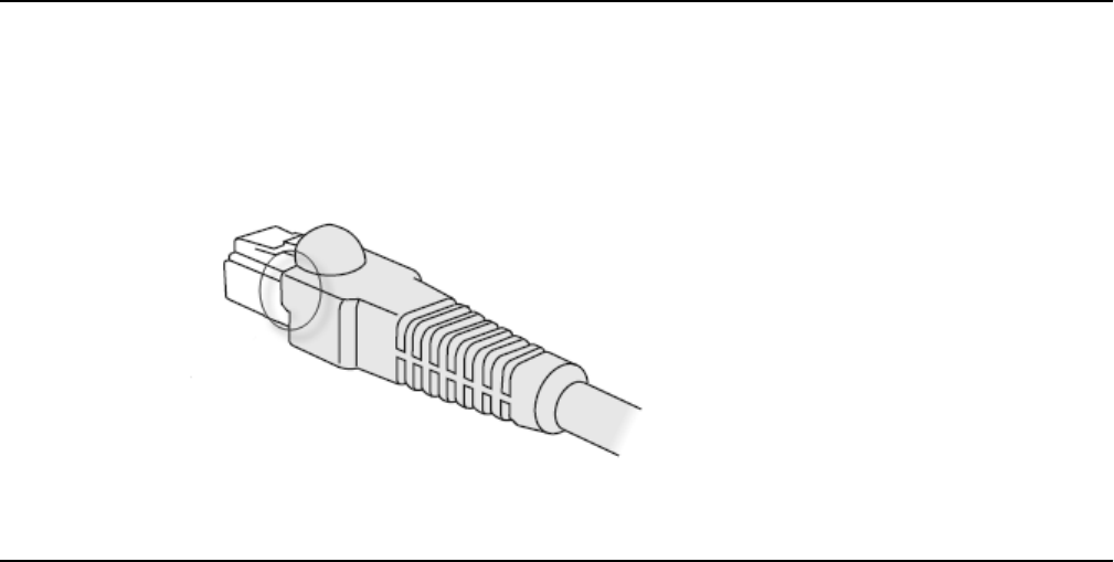
The Ethernet ports on the access point cannot accept a CAT-5 cable that has an uneven sheath
as shown below. The RJ-45 connector on the cable will not seat properly in the receptacle on
the access point. Use a CAT-5 cable with an even sheath instead.
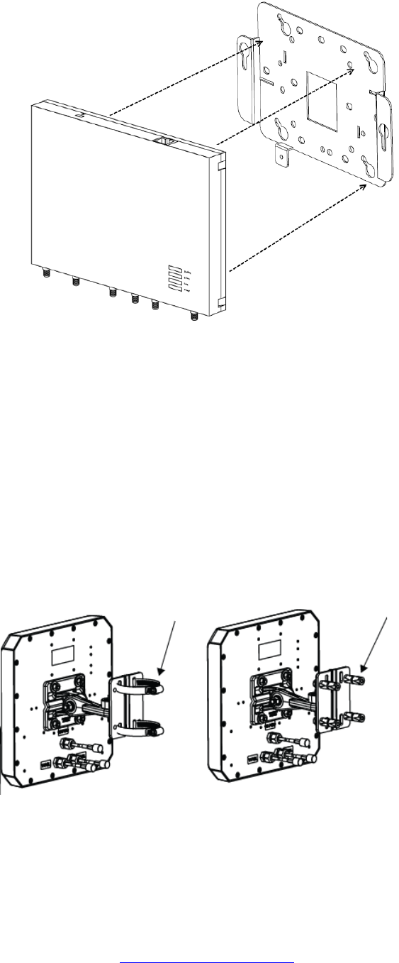
Mounting the WLAN AP 8120 with External Antenna on a
wall
The WLAN AP 8120 with External Antenna installs similarly to the WLAN AP 8120. In addition
to installing the access point itself, with the WLAN AP 8120 with External Antenna you must
also mount the adjoining antennas. You can mount the WLAN AP 8120 with External Antenna
on the wall using wall anchors.
Plan your installation to allow for the installation of both the access point and the antennas.
Ensure you have the correct length of cable to connect the access point to the antennas. Each
antenna comes with three 3–ft pre-installed permanent cables. If your installation distance is
greater than the length of the original cables, you can attach additional 10–ft extension
cables.
Avaya WLAN 8100 Regulatory Information - WLAN AP 8120 with External Antenna October 2011 17
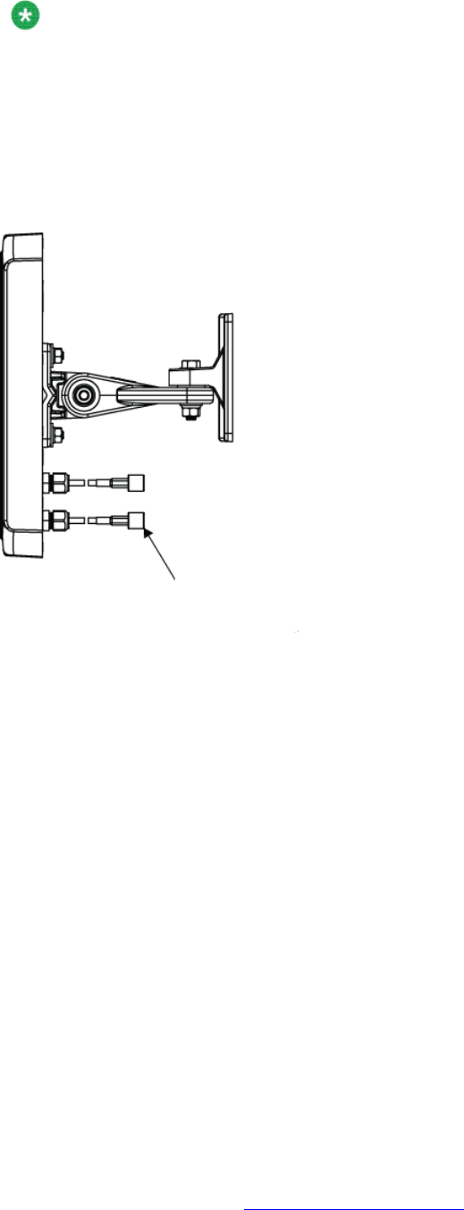
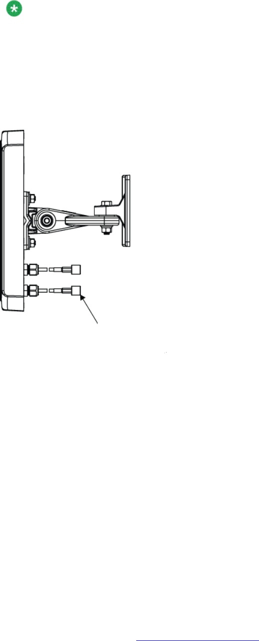
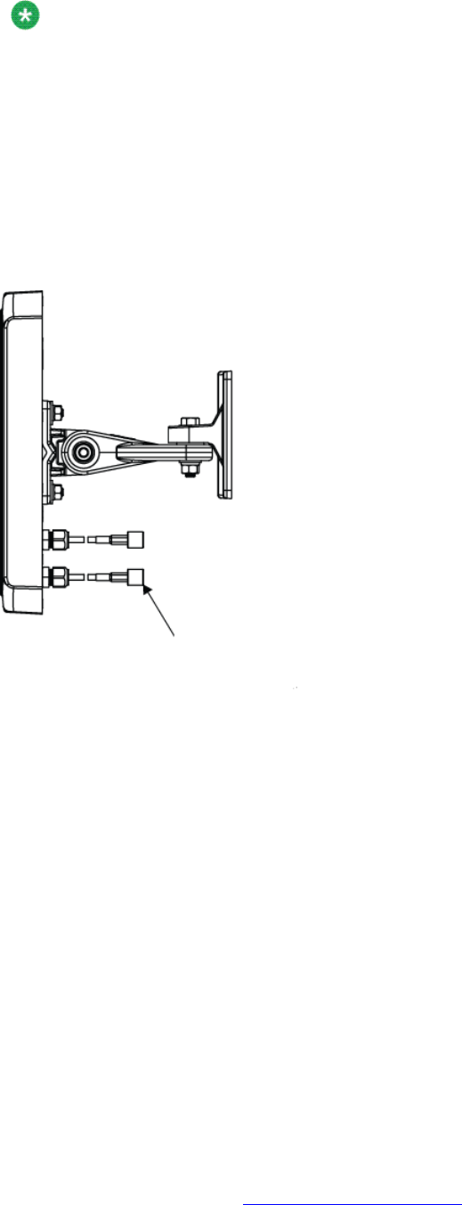
Note:
Assembling the external antenna to the WLAN AP 8120 with External Antenna is completed
through Reverse Polarity SMA (RP-SMA) connectors. The installer should properly torque
the connector using a 5/16 inch torque wrench that is set to 3-5 in·lbf (0.3 to 0.6 N·m) for
brass, and 7-10 in·lbf (0.8–1.1 N·m) for stainless steel connectors. Flats are also provided
on the cable side of the connector assembly so that you use a second wrench to prevent it
rotating and damaging the joint to the cable. Avaya also recommends that you clean out
loose debris from the internal surfaces before connecting.
Laird antenna with arrow showing reverse polarity connector
The mounting bracket is designed to use wall anchors with threaded section diameters ranging
between 3.5mm and 4.5mm. If wall anchors have threaded diameters greater than 3.5mm,
only the two mounting holes marked ‘A’ may be used. If wall anchors have threaded diameters
of less than 3.5mm, the holes marked ‘A’ and the holes marked ‘B’ may be used. All wall
anchors must have a head diameter of less than 10mm or the wall mounting bracket cannot
be installed over them.
Perform the following procedure to mount a wireless LAN access point on a wall:
Procedure
1. Locate the appropriate position of the wall anchors. The wall anchors should be
95mm apart horizontally and 80mm apart vertically.
English
18 Avaya WLAN 8100 Regulatory Information - WLAN AP 8120 with External Antenna October 2011
Comments? infodev@avaya.com

The wall bracket is designed to use a minimum of 2 anchors and a maximum of
4.
2. Install the screws into the wall anchors but do not seat them fully, leave at least a
2mm gap between the screw head and the wall.
3. Slip the wall bracket over the heads of the screws and slide the bracket to the right
as viewed facing the wall.
4. Tighten the screws to secure the wall mounting bracket tightly against the wall.
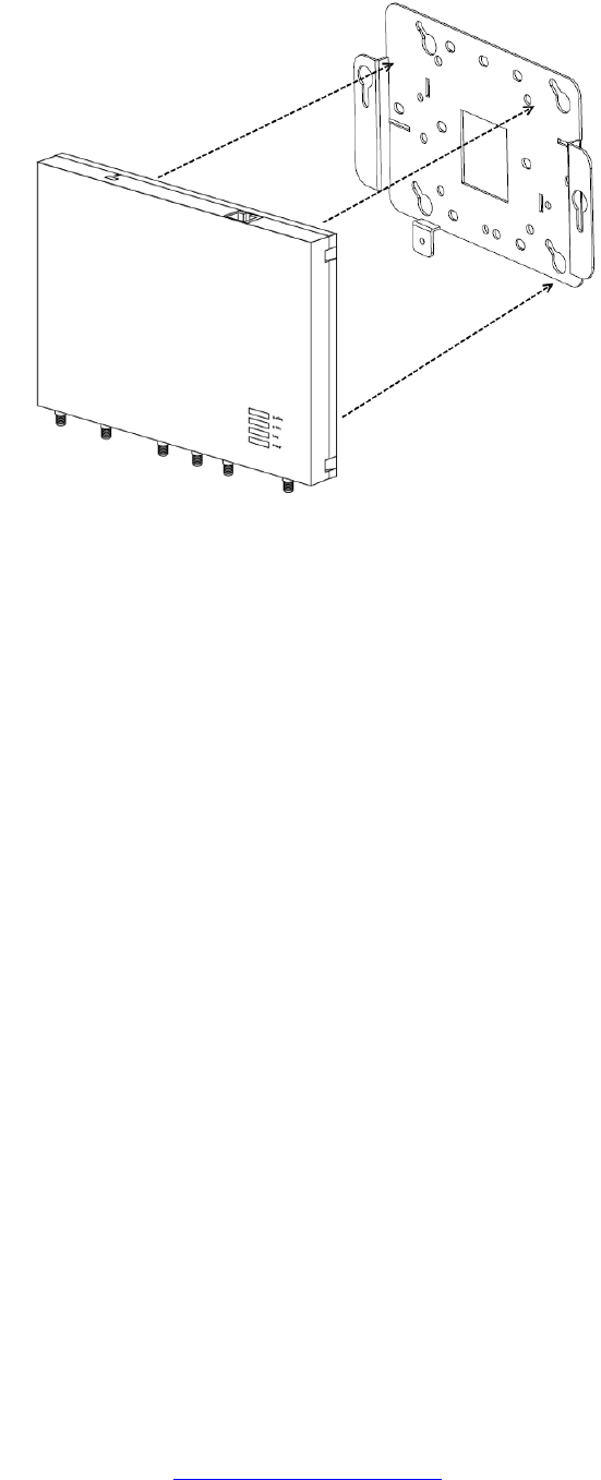
5. Align the mounting tabs on the bottom of the access point sheet metal enclosure
with the vertically oriented keyhole slots in the mounting bracket.
Mounting the WLAN AP 8120 with External Antenna on a wall
Avaya WLAN 8100 Regulatory Information - WLAN AP 8120 with External Antenna October 2011 19
6. Allow the access point to slide down the keyhole slots, making sure the access point
mounting tabs are seated at the bottom of the slot.
7. Secure the access point to the wall mounting bracket and tighten the
thumbscrews.
8. Verify that the access point is secured to both the bracket and to the wall.
9. Mount the external antennas to the wall within the specified distance from the
access point.
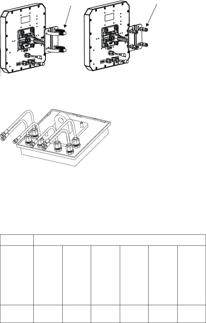
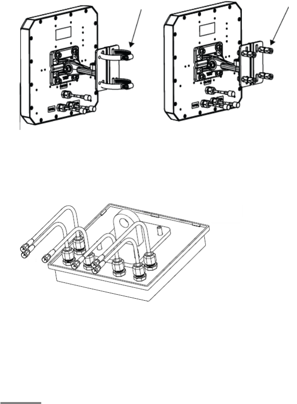
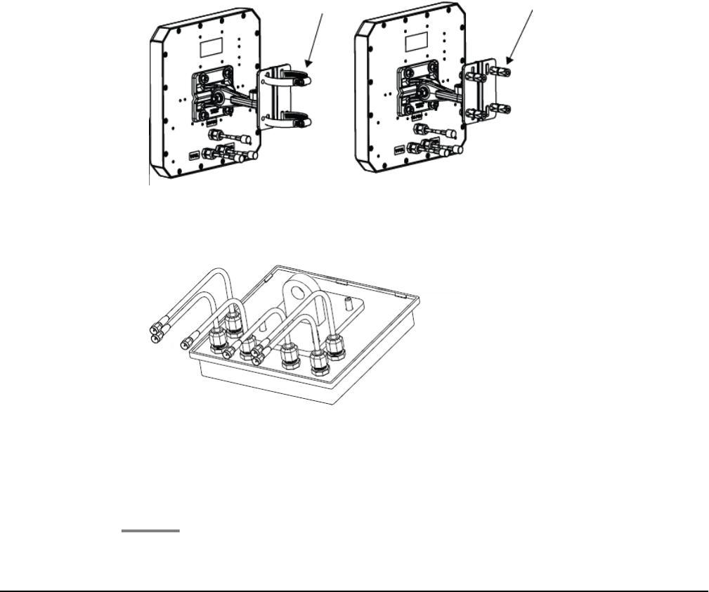
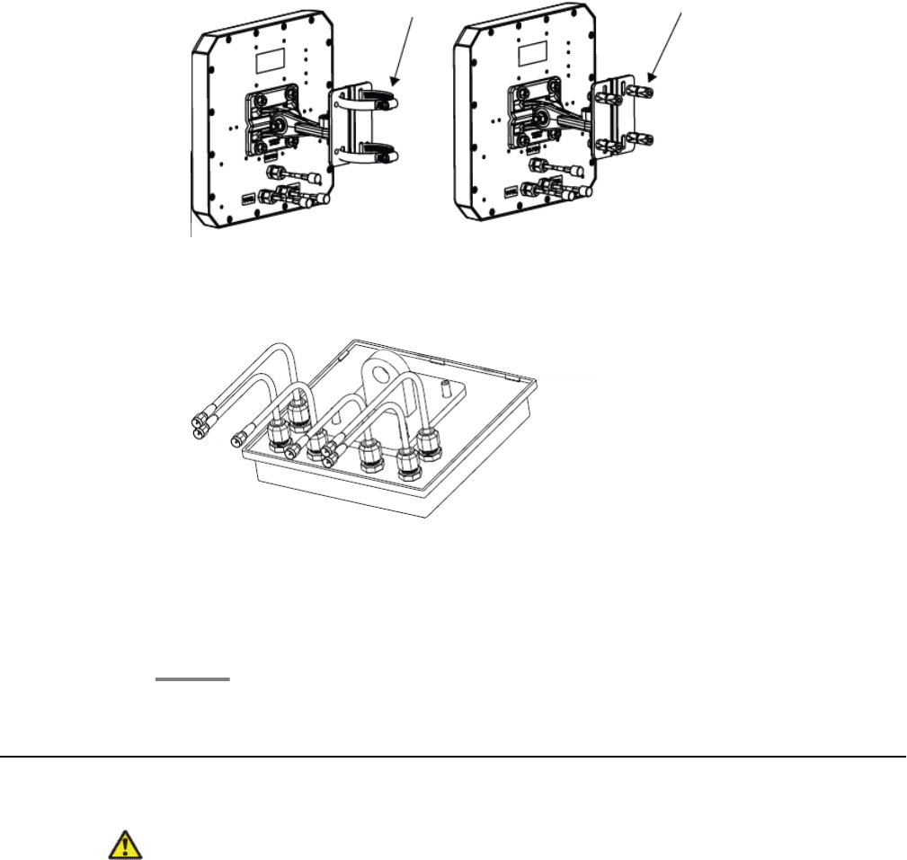
If you are installing Laird antennas, you can mount the antennas on a mast or
vertical surface (wall) using the articulated mount and mounting bolts.
Laird antennas with arrows showing mast (left) and wall mount (right) options
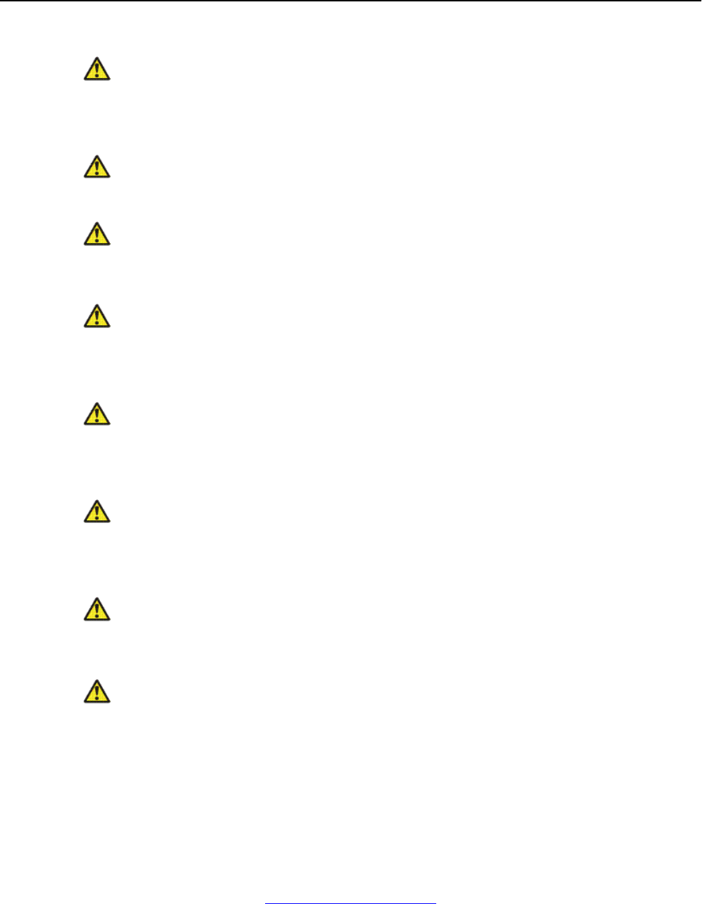
If you are installing TYCO antennas, attach mounting brackets to the wall and attach
the antennas to the mounting brackets.
TYCO antenna showing attached cables
English
20 Avaya WLAN 8100 Regulatory Information - WLAN AP 8120 with External Antenna October 2011
Comments? infodev@avaya.com
10. Verify that the antennas are securely mounted to the wall (or mast, in the case of a
Laird antenna installation).
11. Attach the antenna cables to the access point.
Use the following table to match the 180 degree TYCO antenna and the 70 degree Laird
antenna connectors to the AP8120 - with External Antenna inputs with the cables. The 180
degree TYCO antenna connectors are labeled the same as the AP8120 - with External
Antenna inputs.
Hardware Inputs
AP8120-
with
External
Antenna
inputs/ 180
degree
TYCO
antenna
2.5G #1 2.5G #2 2.5G #3 5G #1 5G #2 5G #3
70 degree
Laird
antenna
inputs
V-Pol H-POL V-POL V-Pol H-POL V-POL
12. Make electrical connections.
Installing the WLAN AP 8120 with External Antenna to the
ceiling
The WLAN AP 8120 with External Antenna installs similarly to the WLAN AP 8120. In addition
to installing the access point itself, with the WLAN AP 8120 with External Antenna you must
also mount the adjoining antennas. You can mount the WLAN AP 8120 with External Antenna
on the ceiling using a ceiling grid adaptor.
Plan your installation to allow for the installation of both the access point and the antennas.
Ensure you have the correct length of cable to connect the access point to the antennas. Each
antenna comes with three 3–ft pre-installed permanent cables. If your installation distance is
Installing the WLAN AP 8120 with External Antenna to the ceiling
Avaya WLAN 8100 Regulatory Information - WLAN AP 8120 with External Antenna October 2011 21
greater than the length of the original cables, you can attach additional 10–ft extension
cables.
Note:
Assembling the external antenna to the WLAN AP 8120 with External Antenna is completed
through Reverse Polarity SMA (RP-SMA) connectors. The installer should properly torque
the connector using a 5/16 inch torque wrench that is set to 3-5 in·lbf (0.3 to 0.6 N·m) for
brass, and 7-10 in·lbf (0.8–1.1 N·m) for stainless steel connectors. Flats are also provided
on the cable side of the connector assembly so that you use a second wrench to prevent it
rotating and damaging the joint to the cable. Avaya also recommends that you clean out
loose debris from the internal surfaces before connecting.
Laird antenna with arrow showing reverse polarity connector
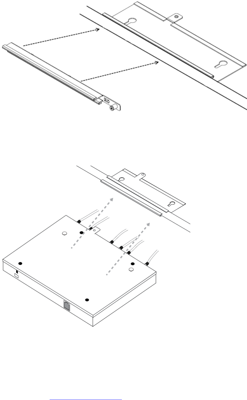
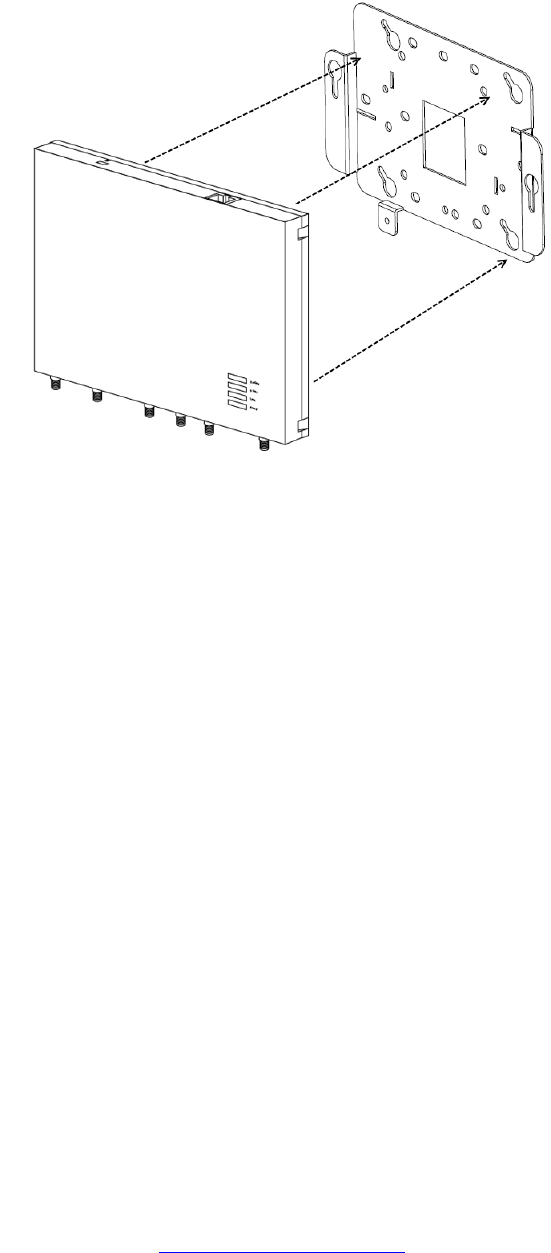
The ceiling grid adaptor comes with two interlocking bracket parts. The larger bracket includes
keyhole shaped slots which mate with tabs on the under surface of the AP and a threaded hole
that mates with the captive thumbscrew on the AP. The smaller bracket also includes a captive
fastener and it can be oriented with respect to the larger bracket in two different ways
corresponding to narrow or wide ceiling grids.
Perform the following procedure to install the access point with a ceiling grid adaptor:
Procedure
1. Secure a safe work environment. Obtain a ladder that allows easy access to the
ceiling grid system.
2. Identify an appropriate location on the ceiling grid where the ceiling T-bars are safely
accessible and where the ceiling tiles can be temporarily elevated and cleared away
from the work area. The adaptor bracket assembly is intended for use with the thin
section grid runners, not the thicker section runners used to cross large spans. To
provide access for hands and tools, use a pair of pencils or sticks to hold up the
English
22 Avaya WLAN 8100 Regulatory Information - WLAN AP 8120 with External Antenna October 2011
Comments? infodev@avaya.com

ceiling tiles out of the grid. Doing this provides easy access for securing the bracket
to the grid.
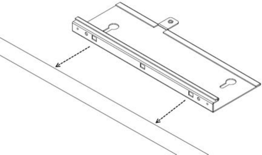
3. Mount the larger bracket to the grid. While installing, pay attention to the width of
the grid strip in order to ascertain the appropriate orientation for the smaller bracket
which is installed next.
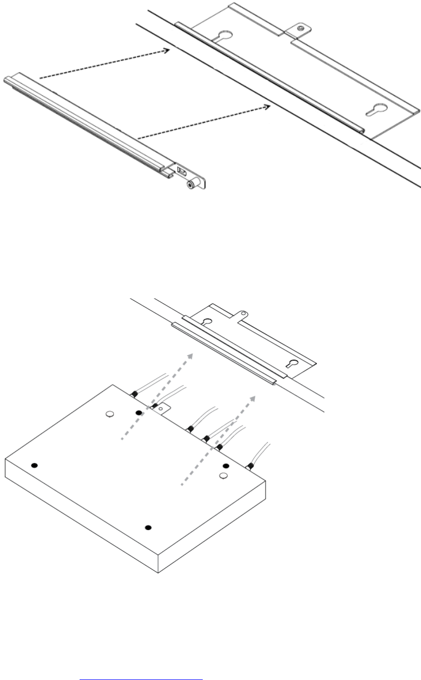
4. Mount the interlocking small bracket to the large bracket and clamp the two pieces
together on the grid. The smaller bracket has tabs formed into it which engage slots
in the larger tab. This allows the two parts to slide together and lock to one another.
When this is done, the two brackets effectively clamp themselves around the ceiling
grid. When the two halves of the bracket are correctly slid together, the captive
fastener in the small bracket should engage threads provided in the larger bracket.
Use a screwdriver to screw down the captive fastener. Securing the two brackets
in this manner is essential to prevent them from disengaging from one another.
Tighten the captive fastener screw securely.
Installing the WLAN AP 8120 with External Antenna to the ceiling
Avaya WLAN 8100 Regulatory Information - WLAN AP 8120 with External Antenna October 2011 23
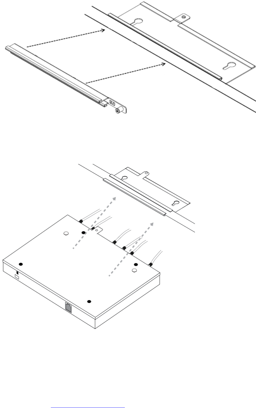
5. Attach the access point to the bracket. Align the access point securing tabs with the
keyhole slots in the ceiling grid bracket and carefully slide the access point onto the
ceiling grid bracket assembly. If the access point and the bracket assembly are
correctly engaged, it should be possible to engage the access points captive
thumbscrew into the threaded tab provided on the ceiling grid bracket.
6. Mount the external antennas to the wall within the specified distance from the
access point.
English
24 Avaya WLAN 8100 Regulatory Information - WLAN AP 8120 with External Antenna October 2011
Comments? infodev@avaya.com
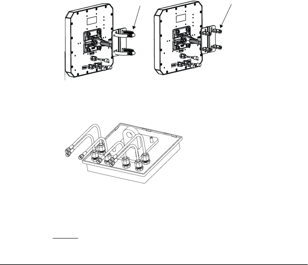
If you are installing Laird antennas with articulated mount, you must attach the
antennas to a mast or a vertical surface using the articulated mount and mounting
bolts.
Laird antennas with arrows showing mast (left) and wall mount (right) options
If you are installing TYCO antennas, attach mounting brackets to the wall and attach
the antennas to the mounting brackets.
TYCO antenna showing attached cables
7. Verify that the antennas are securely mounted to the ceiling (or mast or vertical
surface, in the case of a Laird antenna installation).
8. Attach the antenna cables to the access point.
Use the following table to match the 180 degree TYCO antenna and the 70 degree Laird
antenna connectors to the AP8120 - with External Antenna inputs with the cables. The 180
degree TYCO antenna connectors are labeled the same as the AP8120 - with External
Antenna inputs.
Hardware Inputs
AP8120-
with
External
Antenna
inputs/ 180
degree
TYCO
antenna
2.5G #1 2.5G #2 2.5G #3 5G #1 5G #2 5G #3
70 degree
Laird V-Pol H-POL V-POL V-Pol H-POL V-POL
Installing the WLAN AP 8120 with External Antenna to the ceiling
Avaya WLAN 8100 Regulatory Information - WLAN AP 8120 with External Antenna October 2011 25
antenna
inputs
9. Make electrical connections and return ceiling tiles.
Safety Messages
Caution:
The Avaya WLAN AP 8120 with External Antenna radios are disabled by default and can
be enabled only by a system administrator.
Warning:
This situation or condition can cause injury.
Warning:
High voltage. This situation or condition can cause injury due to electric shock.
Warning:
Only qualified service personnel must perform installation. Read and follow all warning
notices and instructions marked on the product or included in the documentation.
Warning:
Install this device in such a manner as to maintain a minimum of 24.9 cm (9.8 inches)
separation distance between the radiating element(s) and all persons. This safety warning
conforms with FCC radio frequency exposure limits.
Warning:
Do not operate access point near unshielded blasting caps or in an otherwise explosive
environment unless the device has been modified for such use by qualified personnel.
Warning:
Do not touch or move the access point when the antennas are transmitting or receiving.
Warning:
Before using a wireless device in a hazardous location, consult the local codes, national
codes, and safety directors of the location for usage constraints.
English
26 Avaya WLAN 8100 Regulatory Information - WLAN AP 8120 with External Antenna October 2011
Comments? infodev@avaya.com

Chapter 4: Deutsch
Verwenden Sie die folgenden Verfahren und Informationen zur Installation der Access Points Avaya
WLAN AP 8120 mit externer Antenne.
Kabelanschlüsse
An die Ethernet-Ports an den Access Points können nicht CAT 5-Kabel mit abgesetzter
Kabelhülse angeschlossen werden (siehe unten). Der RJ-45-Anschluss des Kabels sitzt in
diesem Fall nicht richtig auf dem Port des Access Points auf. Verwenden Sie stattdessen ein
CAT 5-Kabel mit einer geraden Kabelhülse.
Wandmontage des WLAN AP 8120 mit externer Antenne
Bei der Montage des WLAN AP 8120 mit externer Antenne ist ähnlich vorzugehen wie bei der
Montage des WLAN AP 8120. Zusätzlich zur Installation des Access Point müssen beim
Modell „WLAN AP 8120 mit externer Antenne“ außerdem die zugehörigen Antennen
angebracht werden. Sie können bei der Deckenmontage des WLAN AP 8120 mit externer
Antenne Wanddübel verwenden.
Berücksichtigen Sie bei der Planung der Montage den Platzbedarf des Access Point und der
Antennen. Sie benötigen ausreichend Kabellänge, um den Access Point mit den Antennen
verbinden zu können. An jeder Antenne ist ein 90 cm langes Kabel untrennbar angebracht.
Wenn das Kabel zu kurz ist für den Abstand zwischen Access Point und Antenne, können Sie
ein 3 Meter langes Zwischenkabel einsetzen.
Avaya WLAN 8100 Regulatory Information - WLAN AP 8120 with External Antenna October 2011 27

Note:
Der Anschluss der externen Antenne an den WLAN AP 8120 mit externer Antenne erfolgt
mit SMA-Steckverbindern mit umgekehrter Polarität (RP-SMA). Der Monteur muss den
Steckverbinder mit einem Drehmomentschlüssel (5/16", 8 mm) festziehen. Für
Messingstecker muss ein Drehmoment zwischen 0,3 und 0,6 Nm (3-5 in lbf) eingestellt
werden, für Edelstahlstecker ein Drehmoment zwischen 0,8 und 1,1 Nm (7-10 in lbf). Am
Stecker ist kabelseitig eine Abflachung vorhanden. An diese kann ein zweiter
Schraubenschlüssel zum Dagegenhalten angesetzt werden. Das Kabel kann sich dann
nicht mitdrehen, und die Kabelverbindung wird nicht beschädigt. Avaya empfiehlt
außerdem, vor dem Anschließen losen Schmutz aus dem Innenbereich des Steckers zu
entfernen.
Laird-Antennen. Die Pfeile zeigen auf die Steckverbinder mit umgekehrter Polarität.
Die Wandhalterung wird mit Wanddübeln mit einem Gewindedurchmesser von 3,5-4,5 mm
befestigt. Bei Gewindedurchmessern über 3,5 mm dürfen nur die mit „A“ markierten
Montagelöcher der Wandhalterung verwendet werden. Bei Gewindedurchmessern unter
3,5 mm können Sie die mit „A“ und die mit „B“ markierten Montagelöcher verwenden. Der
Kopfdurchmesser des Wanddübels muss kleiner als 10 mm sein, damit die Wandhalterung
richtig montiert werden kann.
So bringen Sie einen Wireless LAN Access Point an der Wand an:
Procedure
1. Bestimmen Sie die richtige Position der Wanddübel. Die Wanddübel müssen
waagerecht in einem Abstand von 95 mm und senkrecht in einem Abstand von
80 mm eingebracht werden.
Deutsch
28 Avaya WLAN 8100 Regulatory Information - WLAN AP 8120 with External Antenna October 2011
Comments? infodev@avaya.com

Die Wandhalterung wird mit mindestens 2 und höchstens 4 Schrauben befestigt.
2. Drehen Sie die Schrauben in die Wand, aber ziehen Sie sie nicht ganz fest. Lassen
Sie einen Abstand von mindestens 2 mm zwischen dem Schraubenkopf und der
Wand.
3. Setzen Sie die Wandhalterung auf die Schraubenköpfe auf. Schieben Sie die
Halterung nach rechts (von Ihnen aus gesehen).
4. Befestigen Sie die Wandhalterung durch Festziehen der Schrauben sicher an der
Wand.
5. Richten Sie die Montagelaschen unten am Metallgehäuse des Access Point auf die
senkrechten Längsschlitze an der Wandhalterung aus.
Wandmontage des WLAN AP 8120 mit externer Antenne
Avaya WLAN 8100 Regulatory Information - WLAN AP 8120 with External Antenna October 2011 29
6. Schieben Sie den Access Point vorsichtig in den Längsschlitzen nach unten, sodass
die Montagelaschen des Access Point am unteren Rand der Längsschlitze
aufsitzen.
7. Befestigen Sie den Access Point an der Wandhalterung, und ziehen Sie die
Daumenschrauben an.
8. Prüfen Sie, ob der Access Point sicher an der Wandhalterung und an der Wand
angebracht ist.
9. Bringen Sie die externen Antennen an der Wand an. Halten Sie dabei den
vorgeschriebenen Abstand zum Access Point ein.
Laird-Antennen können an einem Mast oder einer senkrechten Fläche (Wand)
angebracht werden. Verwenden Sie dazu die Gelenkhalterung und die
Montageschrauben.
Laird-Antennen. Die Pfeile zeigen auf die Halterungsoptionen „Mast“ (links)
und „Wand“ (rechts).
Deutsch
30 Avaya WLAN 8100 Regulatory Information - WLAN AP 8120 with External Antenna October 2011
Comments? infodev@avaya.com
Werden TYCO-Antennen verwendet, müssen die Montagehalterungen an die
Wand montiert werden. Die Antennen werden auf die Montagehalterungen
aufgesetzt.
TYCO-Antenne mit aufgeschraubten Kabeln
10. Prüfen Sie, ob die Antennen sicher an der Wand (bzw. am Mast, falls Laird-
Antennen verwendet werden) montiert sind.
11. Schließen Sie die Antennenkabel an den Access Point an.
12. Stellen Sie die elektrischen Verbindungen her.
Deckenmontage des WLAN AP 8120 mit externer Antenne
Bei der Montage des WLAN AP 8120 mit externer Antenne ist ähnlich vorzugehen wie bei der
Montage des WLAN AP 8120. Zusätzlich zur Installation des Access Point müssen beim
Modell „WLAN AP 8120 mit externer Antenne“ außerdem die zugehörigen Antennen
angebracht werden. Sie können bei der Deckenmontage des WLAN AP 8120 mit externer
Antenne einen Adapter für die Deckenmontage verwenden.
Berücksichtigen Sie bei der Planung der Montage den Platzbedarf des Access Point und der
Antennen. Sie benötigen ausreichend Kabellänge, um den Access Point mit den Antennen
verbinden zu können. An jeder Antenne ist ein 90 cm langes Kabel untrennbar angebracht.
Wenn das Kabel zu kurz ist für den Abstand zwischen Access Point und Antenne, können Sie
ein 3 Meter langes Zwischenkabel einsetzen.
Deckenmontage des WLAN AP 8120 mit externer Antenne
Avaya WLAN 8100 Regulatory Information - WLAN AP 8120 with External Antenna October 2011 31
Note:
Der Anschluss der externen Antenne an den WLAN AP 8120 mit externer Antenne erfolgt
mit SMA-Steckverbindern mit umgekehrter Polarität (RP-SMA). Der Monteur muss den
Steckverbinder mit einem Drehmomentschlüssel (5/16", 8 mm) festziehen. Für
Messingstecker muss ein Drehmoment zwischen 0,3 und 0,6 Nm (3-5 in lbf) eingestellt
werden, für Edelstahlstecker ein Drehmoment zwischen 0,8 und 1,1 Nm (7-10 in lbf). Am
Stecker ist kabelseitig eine Abflachung vorhanden. An diese kann ein zweiter
Schraubenschlüssel zum Dagegenhalten angesetzt werden. Das Kabel kann sich dann
nicht mitdrehen, und die Kabelverbindung wird nicht beschädigt. Avaya empfiehlt
außerdem, vor dem Anschließen losen Schmutz aus dem Innenbereich des Steckers zu
entfernen.
Laird-Antennen. Die Pfeile zeigen auf die Steckverbinder mit umgekehrter Polarität.
Der Adapter für die Deckenmontage verfügt über zwei ineinander greifende Halterungen. Die
Montagelaschen unten am Access Point passen in die Längsschlitze an der größeren
Halterung. Die unverlierbare Schraube am Access Point wird in das Gewindeloch an der
größeren Haltung geschraubt. Die unverlierbare Schraube an der kleineren Halterung kann je
nach Rastergröße auf zweierlei Weise an der größeren Halterung ausgerichtet werden.
So montieren Sie einen Access Point an einer Rasterdecke:
Procedure
1. Sorgen Sie für eine sichere Arbeitsumgebung. Sie benötigen eine Leiter, auf der
Sie zur Rasterdecke hochsteigen können.
2. Bestimmen Sie eine geeignete Montageposition an der Rasterdecke. Die T-Profile
müssen sicher zugänglich sein und die Deckenplatten müssen vorübergehend
abgehängt werden können. Der Adapter für die Deckenmontage wird an den
dünneren Querschienen befestigt, nicht an den dickeren und längeren
Haupttrageschienen. Um ungehindert arbeiten zu können, heben Sie die
Deutsch
32 Avaya WLAN 8100 Regulatory Information - WLAN AP 8120 with External Antenna October 2011
Comments? infodev@avaya.com

Deckenplatten mit zwei Stiften oder Stäben nach oben aus dem Deckenraster. So
erhalten Sie einfachen Zugang zum Befestigen der Halterung.
3. Befestigen Sie die größere Halterung am Deckenraster. Achten Sie dabei auf die
Breite der Schiene, um die richtige Positionierung für die kleinere Halterung zu
bestimmen, die anschließend montiert wird.
4. Montieren Sie die kleinere Halterung so an der größeren, dass sie ineinander
greifen, und klemmen Sie die beiden Halterungen zusammen. Die Montagelaschen
der kleineren Halterung passen in die Schlitze der größeren Halterung. So können
die beiden Halterungen sicher arretiert und um die Deckenschiene herum montiert
werden. Wenn Sie die beiden Halterungen richtig miteinander verbunden haben,
passt die unverlierbare Schraube an der kleineren Halterung in das Gewinde in der
größeren Halterung. Sichern Sie die unverlierbare Schraube mit einem
Schraubendreher. Es ist sehr wichtig, die beiden Halterungen auf diese Weise zu
sichern, damit sie sich nicht voneinander lösen. Ziehen Sie die unverlierbare
Schraube fest an.
Deckenmontage des WLAN AP 8120 mit externer Antenne
Avaya WLAN 8100 Regulatory Information - WLAN AP 8120 with External Antenna October 2011 33
5. Befestigen Sie den Access Point an der Halterung. Richten Sie die
Sicherungslaschen am Access Point an den Längsschlitzen an der
Deckenhalterung aus, und schieben Sie den Access Point vorsichtig auf die
montierte Deckenhalterung. Wenn der Access Point richtig auf die Deckenhalterung
aufgesetzt ist, kann die unverlierbare Daumenschraube auf dem Access Point in
das Gewinde an der Deckenhalterung geschraubt werden.
6. Bringen Sie die externen Antennen an der Wand an. Halten Sie dabei den
vorgeschriebenen Abstand zum Access Point ein.
Deutsch
34 Avaya WLAN 8100 Regulatory Information - WLAN AP 8120 with External Antenna October 2011
Comments? infodev@avaya.com
Laird-Antennen mit Gelenkmechanismus müssen an einem Mast oder einer
senkrechten Fläche angebracht werden. Verwenden Sie dazu die Gelenkhalterung
und die Montageschrauben.
Laird-Antennen. Die Pfeile zeigen auf die Halterungsoptionen „Mast“ (links)
und „Wand“ (rechts).
Werden TYCO-Antennen verwendet, müssen die Montagehalterungen an die
Wand montiert werden. Die Antennen werden auf die Montagehalterungen
aufgesetzt.
TYCO-Antenne mit aufgeschraubten Kabeln
7. Prüfen Sie, ob die Antennen sicher auf der Decke (bzw. am Mast oder auf
senkrechter Fläche, falls Laird-Antennen verwendet werden) montiert sind.
8. Schließen Sie die Antennenkabel an den Access Point an.
9. Stellen Sie die elektrischen Verbindungen her, und setzen Sie die Deckenplatten
wieder ein.
Deckenmontage des WLAN AP 8120 mit externer Antenne
Avaya WLAN 8100 Regulatory Information - WLAN AP 8120 with External Antenna October 2011 35
Sicherheitshinweise
Caution:
Die Frequenzempfänger des Avaya WLAN AP 8120 mit externer Antenne sind
standardmäßig deaktiviert und können nur von einem Systemadministrator aktiviert
werden.
Warning:
Dieser Zustand bzw. diese Bedingung kann zu Verletzungen führen.
Warning:
Hochspannung. Dieser Zustand bzw. diese Bedingung kann aufgrund von Stromschlag zu
Verletzungen führen.
Warning:
Die Installation darf nur von qualifiziertem Wartungspersonal durchgeführt werden. Lesen
und befolgen Sie alle Warnhinweise und Anweisungen, die am Produkt angebracht oder in
der Dokumentation zu finden sind.
Warning:
Installieren Sie das Gerät so, dass zwischen den Strahlungselementen und allen Personen
ein Abstand von mindestens 24,9 cm gewährleistet ist. Diese Sicherheitswarnung entspricht
den FCC-Grenzwerten für Hochfrequenzstrahlung.
Warning:
Setzen Sie den Access Point nicht in der Nähe von ungeschützten Zündkapseln oder in
anderen Umgebungen mit Explosionsgefahr ein, es sei denn, das Gerät wurde von
qualifiziertem Personal für einen solchen Einsatz modifiziert.
Warning:
Berühren oder bewegen Sie den Access Point nicht, wenn die Antennen gerade
Funksignale senden oder übertragen.
Warning:
Informieren Sie sich vor der Verwendung eines Wireless-Geräts in einer
Gefahrenumgebung über regionale und überregionale Vorschriften zu
Nutzungsbeschränkungen sowie die Sicherheitsrichtlinien für den jeweiligen Standort.
Deutsch
36 Avaya WLAN 8100 Regulatory Information - WLAN AP 8120 with External Antenna October 2011
Comments? infodev@avaya.com

Chapter 5: Español
Al momento de instalar los puntos de acceso WLAN AP 8120 con antena externa de Avaya, tenga en
cuenta el procedimiento y la información que se presentan a continuación.
Requisitos de cableado
Los puertos de Ethernet en el punto de acceso no pueden aceptar un cable CAT-5 que tenga
una cubierta despareja, como se muestra a continuación. El conector RJ-45 del cable no se
fijará correctamente en el receptáculo en el punto de acceso. Use un cable CAT-5 con una
cubierta pareja.
Cómo montar la WLAN AP 8120 con antena externa en una
pared
La WLAN AP 8120 con la antena externa se instala en forma similar a la WLAN AP 8120.
Además de instalar el punto de acceso en sí mismo, con la WLAN AP 8120 con antena externa,
también debe montar las antenas unidas. Puede montar la WLAN AP 8120 con antena externa
en la pared utilizando anclajes para pared.
Planifique la instalación para tener en cuenta tanto la instalación del punto de acceso como
de las antenas. Asegúrese de tener la longitud de cable correcta para conectar el punto de
acceso a las antenas. Cada antena incluye tres cables permanentes preinstalados de 3 pies.
Si la distancia de instalación es mayor que la longitud de los cables originales, puede adjuntar
cables de extensión adicionales de 10 pies.
Avaya WLAN 8100 Regulatory Information - WLAN AP 8120 with External Antenna October 2011 37

Note:
La instalación de la antena externa con la WLAN AP 8120 con antena externa se completa
a través de conectores de polaridad invertida SMA (RP-SMA). El instalador debe ajustar
correctamente el conector usando una llave dinamométrica de 5/16 pulgadas ajustada a
3-5 libras pulgadas (in-lbf) (0,3 a 0,6 N·m) para conectores de bronce y 7-10 in-lbf (0,8–1,1
N·m) para conectores de acero inoxidable. También se proveen caras planas del lado del
cable de la unidad del conector para utilizar una segunda llave para impedir que gire y dañe
el ensamble al cable. Avaya también recomienda limpiar los desechos sueltos de las
superficies internas antes de conectar.
Antena Laird con flecha que muestra el conector con polaridad invertida.
El soporte de montaje está diseñado para usar anclajes de pared con diámetros de sección
roscada de entre 3,5 mm y 4,5 mm. Si los anclajes de pared tienen diámetros roscados de
más de 3,5 mm, solo pueden usarse los orificios de montaje marcados "A". Si los anclajes de
pared tienen diámetros roscados de menos de 3,5 mm, pueden usarse los orificios marcados
"A" y los marcados "B". Todos los anclajes de pared deben tener un diámetro de cabezal de
menos de 10 mm, de lo contrario, el soporte de montaje de pared no podrán instalarse sobre
ellos.
Realice el siguiente procedimiento para montar un punto de acceso LAN inalámbrico en una
pared:
Procedure
1. Ubique la posición correcta de los anclajes de pared. Los anclajes de pared deben
estar separados con una distancia de 95 mm en forma horizontal y una distancia
de 80 mm en forma vertical.
Español
38 Avaya WLAN 8100 Regulatory Information - WLAN AP 8120 with External Antenna October 2011
Comments? infodev@avaya.com

El soporte de pared está diseñado para usar un mínimo de 2 anclajes y un máximo
de 4.
2. Instale los tornillos en los anclajes de la pared pero no los inserte por completo,
deje un espacio mínimo de 2 mm entre el cabezal del tornillo y la pared.
3. Deslice el soporte de la pared por los cabezales de los tornillos y deslice el soporte
hacia la derecha visto como de frente a la pared.
4. Ajuste los tornillos para fijar el soporte de montaje de pared con firmeza contra la
pared.
Cómo montar la WLAN AP 8120 con antena externa en una pared
Avaya WLAN 8100 Regulatory Information - WLAN AP 8120 with External Antenna October 2011 39
5. Alinee las lengüetas de montaje en la parte inferior de la caja metálica del punto
de acceso con las ranuras verticales con forma de cerradura del soporte de
montaje.
6. Permita que el punto de acceso se deslice por las ranuras con forma de cerradura,
asegurándose de que las lengüetas de montaje del punto de acceso estén
asentadas en la parte de abajo de la ranura.
7. Asegure el punto de acceso en el soporte de montaje de pared y apriete los tornillos
de ajuste.
8. Verifique que el punto de acceso quede bien sujeto tanto al soporte como a la
pared.
9. Monte las antenas externas a la pared dentro de la distancia especificada del punto
de acceso.
Si instala antenas Laird, puede montarlas en un mástil o en una superficie vertical
(pared) utilizando el montaje articulado y los pernos de montaje.
Antenas Laird con las flechas que muestran las opciones de mástil (izquierda)
y montaje de pared (derecha).
Español
40 Avaya WLAN 8100 Regulatory Information - WLAN AP 8120 with External Antenna October 2011
Comments? infodev@avaya.com
Si instala antenas TYCO, fije los soportes de montaje a la pared y fije las antenas
a los soportes de montaje.
La Antena TYCO muestra los cables conectados.
10. Verifique que las antenas estén montadas de manera segura a la pared (o mástil,
en caso de instalar una antena Laird).
11. Conecte los cables de la antena al punto de acceso.
12. Realice las conexiones eléctricas.
Instalación de la WLAN AP 8120 con la antena externa en el
techo
La WLAN AP 8120 con la antena externa se instala en forma similar a la WLAN AP 8120.
Además de instalar el punto de acceso en sí mismo, con la WLAN AP 8120 con la antena
externa, también debe montar las antenas unidas. Puede montar la WLAN AP 8120 con
antena externa en el techo utilizando un adaptador para las estructuras de los techos.
Planifique la instalación para permitir la instalación tanto del punto de acceso como de las
antenas. Asegúrese de tener la longitud de cable correcta para conectar el punto de acceso
a las antenas. Cada antena incluye tres cables permanentes preinstalados de 3 pies. Si la
distancia de instalación es mayor que la longitud de los cables originales, puede adjuntar
cables de extensión adicionales de 10 pies.
Instalación de la WLAN AP 8120 con la antena externa en el techo
Avaya WLAN 8100 Regulatory Information - WLAN AP 8120 with External Antenna October 2011 41

Note:
La instalación de la antena externa con la WLAN AP 8120 con antena externa se completa
a través de conectores de polaridad invertida SMA (RP-SMA). El instalador se debe ajustar
correctamente al conector usando una llave dinamométrica de 5/16 pulgadas ajustada a
3-5 libras pulgadas (in-lbf) (0,3 a 0,6 N·m) para conectores de bronce y 7-10 in-lbf (0,8–1,1
N·m) para conectores de acero inoxidable. También se proveen caras planas del lado del
cable de la unidad del conector para usar una segunda llave para impedir que gire y dañe
el ensamble al cable. Avaya también recomienda limpiar los desechos sueltos de las
superficies internas antes de conectar.
Antena Laird con flecha que muestra el conector con polaridad invertida.
El adaptador para estructuras de techos incluye un soporte de dos piezas que van conectadas
entre sí. El soporte más grande tiene ranuras con forma de cerradura que coinciden con
lengüetas ubicadas en la superficie inferior del punto de acceso, además de contar con un
orificio roscado para el tornillo imperdible de ajuste manual del punto de acceso. El más
pequeño también incluye un tornillo imperdible y puede orientarse de dos maneras distintas
con respecto al soporte de mayor tamaño a fin de adaptarse a estructuras de techos
desmontables angostas y anchas.
Para instalar el punto de acceso con un adaptador para estructuras de techos desmontables,
siga los pasos que se presentan a continuación:
Procedure
1. Tome las medidas necesarias para garantizar la seguridad del lugar de trabajo.
Consiga una escalera que le permita llegar fácilmente a la estructura del techo
desmontable.
2. Identifique un lugar apropiado en la ubicación del techo desmontable donde pueda
accederse sin correr riesgos a los perfiles en T y donde las placas del cielorraso
puedan levantarse y quitarse momentáneamente del sector de trabajo. El
Español
42 Avaya WLAN 8100 Regulatory Information - WLAN AP 8120 with External Antenna October 2011
Comments? infodev@avaya.com
adaptador sirve para perfiles delgados de techos desmontables, no para los perfiles
más gruesos que se utilizan para cubrir distancias mayores. A fin de poder acceder
al punto de instalación, utilice un par de lápices o palitos para mantener levantadas
las placas del cielorraso de la estructura. De esta manera, resulta fácil llegar con
las manos y las herramientas para sujetar bien el soporte a la estructura.
3. Coloque el soporte más grande en la estructura. Mientras lo hace, fíjese cuál es el
ancho del perfil con objeto de determinar la orientación adecuada del soporte
pequeño que debe instalarse a continuación.
4. Monte el soporte pequeño en el grande y ajuste ambos soportes a la estructura. El
soporte más pequeño tiene lengüetas que encajan en ranuras ubicadas en el
soporte más grande. Esto permite que las dos piezas queden conectadas y se
sujeten entre sí. Cuando esto se realice, los dos soportes efectivamente se
sujetarán con firmeza a la estructura del techo desmontable. Si ambas piezas del
soporte quedar bien conectadas, el tornillo imperdible del soporte pequeño tiene
que quedar alineado con el orificio roscado del soporte grande. Utilice un
destornillador para ajustar el tornillo imperdible. Es muy importante sujetar los dos
soportes soporte de esta manera para impedir que se suelten. Ajuste bien el tornillo
imperdible.
Instalación de la WLAN AP 8120 con la antena externa en el techo
Avaya WLAN 8100 Regulatory Information - WLAN AP 8120 with External Antenna October 2011 43
5. Monte el punto de acceso en el soporte. Alinee las lengüetas del punto de acceso
con las ranuras con forma de cerradura del adaptador para estructuras de techos
desmontables e inserte con cuidado el punto de acceso en el adaptador. Si tanto
el punto de acceso como el adaptador están bien colocados, el tornillo imperdible
de ajuste manual del punto de acceso tiene que coincidir con la lengüeta roscada
del adaptador para estructuras de techos desmontables.
6. Monte las antenas externas a la pared dentro de la distancia especificada del punto
de acceso.
Español
44 Avaya WLAN 8100 Regulatory Information - WLAN AP 8120 with External Antenna October 2011
Comments? infodev@avaya.com
Si instala antenas Laird con montaje articulado, debe conectar las antenas a un
mástil o una superficie vertical utilizando el montaje articulado y los pernos de
montaje.
Las antenas Laird con las flechas que muestran las opciones de mástil
(izquierda) y montaje de pared (derecha).
Si instala antenas TYCO, fije los soportes de montaje a la pared y fije las antenas
a los soportes de montaje.
La antena TYCO muestra los cables conectados.
7. Verifique que las antenas estén montadas de manera segura al techo (o mástil o
superficie vertical, en caso de instalar una antena Laird).
8. Conecte los cables de la antena al punto de acceso.
9. Realice las conexiones eléctricas y vuelva a colocar las placas del cielorraso.
Advertencias de seguridad
Caution:
Las radios WLAN AP 8120 con antena externa de Avaya se encuentran desactivadas de
manera predeterminada, y sólo puede activarlas un administrador de sistemas.
Advertencias de seguridad
Avaya WLAN 8100 Regulatory Information - WLAN AP 8120 with External Antenna October 2011 45

Warning:
Esta situación o estado puede provocar lesiones.
Warning:
Alta tensión. Esta situación o estado puede provocar lesiones por descarga eléctrica.
Warning:
La instalación debe dejarse en manos de personal de servicio técnico especializado. Lea y
respete todas las advertencias de seguridad e instrucciones que figuren en el producto o
en la documentación pertinente.
Warning:
Instale este dispositivo de modo que quede una separación de como mínimo 24,9 cm (9,8
pulgadas) entre las personas y todo lo que emita señales de radiofrecuencia. Esta
advertencia de seguridad se ajusta a los límites de exposición a señales de radiofrecuencia
que dicta la FCC.
Warning:
No utilice el punto de acceso cerca de detonadores sin blindaje ni en ningún tipo de lugar
en que exista riesgo de explosión a menos que personal especializado haya adaptado el
dispositivo para dicho fin.
Warning:
No toque ni mueva el punto de acceso cuando las antenas estén transmitiendo o recibiendo
información.
Warning:
Antes de utilizar un dispositivo inalámbrico en un entorno peligroso, familiarícese con las
normativas locales y nacionales, y consulte al encargado de seguridad del lugar para estar
al tanto de los usos permitidos.
Español
46 Avaya WLAN 8100 Regulatory Information - WLAN AP 8120 with External Antenna October 2011
Comments? infodev@avaya.com
Chapter 6: Français
Utilisez les procédures et informations suivantes lors de l'installation des points d'accès WLAN AP 8120
avec antenne externe d'Avaya.
Configuration requise pour les câbles
Les câbles CAT-5 dotés d'une gaine irrégulière, comme illustré ci-dessous, ne sont pas
adaptés aux ports Ethernet du point d'accès. Sur ce type de câble, le connecteur RJ-45 ne
s'insère pas correctement dans le logement du point d'accès. Utilisez plutôt un câble CAT-5
doté d'une gaine régulière.
Installation murale du point d'accès 8120 WLAN avec
antenne externe
La procédure d'installation du point d'accès 8120 WLAN avec antenne externe est identique
à celle du point d'accès 8120 WLAN. En plus de l'installation du point d'accès proprement dite,
le point d'accès 8120 WLAN avec antenne externe nécessite également le montage des
antennes adjacentes. Vous pouvez utiliser des dispositifs d'ancrage au mur pour fixer le point
d'accès 8120 WLAN avec antenne externe.
Lors de l'installation, pensez à laisser un espace suffisant pour installer à la fois le point d'accès
et les antennes. Vérifiez que la longueur de câble est suffisante pour relier le point d'accès
aux antennes. Chaque antenne est livrée avec des câbles permanents pré-installés d'une
longueur de 0,91 m (3 pieds). Si la distance de votre installation est supérieure à la longueur
des câbles d'origine, vous pouvez utiliser des rallonges supplémentaires d'une longueur de
3,04 m (10 pieds).
Avaya WLAN 8100 Regulatory Information - WLAN AP 8120 with External Antenna October 2011 47
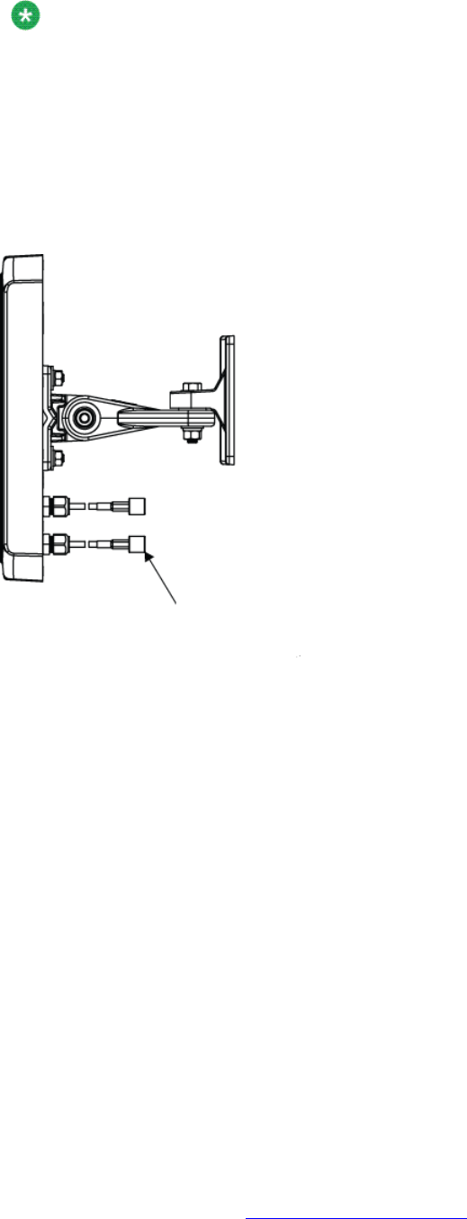
Note:
Des connecteurs SMA à polarité inversée (RP-SMA) permettent de fixer l'antenne externe
au point d'accès 8120 WLAN avec antenne externe. Le connecteur doit être correctement
fixé à l'aide d'une clé dynamométrique de 5/16 pouces réglée sur 0,3 à 0,6 Nm pour les
connecteurs en cuivre et sur 0,8 à 1,1 Nm pour les connecteurs en acier inoxydable. Des
embouts sont également placés au niveau des câbles de l'assemblage de connecteurs afin
qu'une autre clé puisse être utilisée pour éviter toute rotation et endommagement du
raccordement aux câbles. Il est recommandé de nettoyer les dépôts présents sur les
surfaces internes avant de procéder au raccordement.
Antenne Laird avec flèches indiquant un connecteur à polarité inversée
Le support de montage est conçu pour utiliser des dispositifs d'ancrage au mur équipés de
diamètres de filetage de sections allant de 3,5 à 4,5 mm. Si le diamètre de filetage des
dispositifs d'ancrage au mur est supérieur à 3,5 mm, seuls les deux trous de montage marqués
par la lettre A peuvent être utilisés. Si le diamètre de filetage des dispositifs d'ancrage au mur
est inférieur à 3,5 mm, les trous marqués par les lettres A et B peuvent être utilisés. Tous les
dispositifs d'ancrage au mur doivent posséder un diamètre de tête inférieur à 10 mm, sinon ils
ne peuvent pas prendre en charge l'installation du support de montage mural.
Pour monter un point d'accès WLAN sur un mur, procédez comme suit :
Procedure
1. Localisez l'emplacement adéquat pour les dispositifs d'ancrage au mur. Les
dispositifs d'ancrage au mur doivent être écartés de 95 mm horizontalement et
80 mm verticalement.
Français
48 Avaya WLAN 8100 Regulatory Information - WLAN AP 8120 with External Antenna October 2011
Comments? infodev@avaya.com
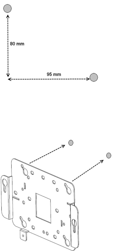
Le support mural est conçu pour utiliser entre 2 et 4 dispositifs d'ancrage.
2. Insérez les vis dans les dispositifs d'ancrage au mur sans les serrer complètement :
laissez un espace de 2 mm au moins entre la tête de la vis et le mur.
3. Glissez le support mural sur les têtes des vis, puis faites-le glisser vers la droite (en
regardant le mur).
4. Serrez les vis afin de fixer solidement le support de montage mural au mur.
5. Alignez les languettes de montage de la partie inférieure du boîtier en tôle du point
d'accès avec les encoches en trous de serrure du support de montage, orientées
à la verticale.
Installation murale du point d'accès 8120 WLAN avec antenne externe
Avaya WLAN 8100 Regulatory Information - WLAN AP 8120 with External Antenna October 2011 49
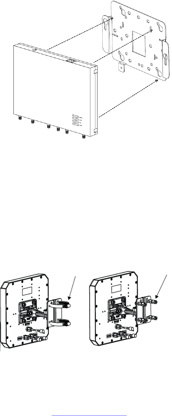
6. Faites glisser le point d'accès dans les encoches en trous de serrure en veillant à
ce que ses languettes de montage soient correctement installées dans la partie
inférieure des encoches.
7. Fixez solidement le point d'accès au support de montage mural et serrez les vis.
8. Vérifiez que le point d'accès est solidement fixé au support et au mur.
9. Fixez les antennes externes au mur en respectant la distance spécifiée par rapport
au point d'accès.
Si vous installez des antennes Laird, vous pouvez les fixer à un support ou à une
surface verticale (mur) à l'aide d'une fixation articulée et de boulons de montage.
Antennes Laird avec flèches indiquant les 2 possibilités d'installation :
support (gauche) et fixation murale (droite)
Pour installer des antennes Tyco, fixez les supports de montage au mur. Installez
ensuite les antennes sur ces supports de montage.
Français
50 Avaya WLAN 8100 Regulatory Information - WLAN AP 8120 with External Antenna October 2011
Comments? infodev@avaya.com
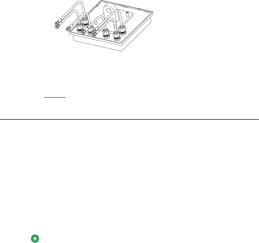
Antenne Tyco avec câbles raccordés
10. Assurez-vous que les antennes sont correctement fixées au mur (ou au support,
en cas d'installation d'une antenne Laird).
11. Raccordez les câbles d'antenne au point d'accès.
12. Effectuez les raccordements électriques.
Installation du point d'accès 8120 WLAN avec antenne
externe au plafond
La procédure d'installation du point d'accès 8120 WLAN avec antenne externe est identique
à celle du point d'accès 8120 WLAN. En plus de l'installation du point d'accès proprement dite,
le point d'accès 8120 WLAN avec antenne externe nécessite également le montage des
antennes adjacentes. Vous pouvez fixer le point d'accès 8120 WLAN avec antenne externe
au plafond à l'aide d'un adaptateur pour grille de plafond.
Lors de l'installation, pensez à laisser un espace suffisant pour installer à la fois le point d'accès
et les antennes. Vérifiez que la longueur de câble est suffisante pour relier le point d'accès
aux antennes. Chaque antenne est livrée avec des câbles permanents pré-installés d'une
longueur de 0,91 m (3 pieds). Si la distance de votre installation est supérieure à la longueur
des câbles d'origine, vous pouvez utiliser des rallonges supplémentaires d'une longueur de
3,04 m (10 pieds).
Note:
Des connecteurs SMA à polarité inversée (RP-SMA) permettent de fixer l'antenne externe
au point d'accès 8120 WLAN avec antenne externe. Le connecteur doit être correctement
fixé à l'aide d'une clé dynamométrique de 5/16 pouces réglée sur 0,3 à 0,6 Nm pour les
connecteurs en cuivre et sur 0,8 à 1,1 Nm pour les connecteurs en acier inoxydable. Des
embouts sont également placés au niveau des câbles de l'assemblage de connecteurs afin
qu'une autre clé puisse être utilisée pour éviter toute rotation et endommagement du
raccordement aux câbles. Il est recommandé de nettoyer les dépôts présents sur les
surfaces internes avant de procéder au raccordement.
Antenne Laird avec flèches indiquant un connecteur à polarité inversée
Installation du point d'accès 8120 WLAN avec antenne externe au plafond
Avaya WLAN 8100 Regulatory Information - WLAN AP 8120 with External Antenna October 2011 51

L'adaptateur pour grille de plafond est fourni avec deux pièces de support croisées. Le grand
support est doté d'encoches en trous de serrure, adaptées aux languettes situées sur la face
inférieure du point d'accès, et d'un trou taraudé adapté à la vis captive du point d'accès. Le
petit support est également doté d'une fixation captive et peut être orienté dans deux directions
différentes par rapport au grand support, s'adaptant ainsi aux grilles de plafond étroites ou
larges.
Pour installer le point d'accès avec un adaptateur pour grille de plafond, procédez comme suit :
Procedure
1. Sécurisez votre environnement de travail. Munissez-vous d'une échelle afin
d'accéder facilement à la grille de plafond.
2. Déterminez un emplacement approprié sur la grille de plafond où les barres en T
sont accessibles en toute sécurité et où les dalles de plafond peuvent être
temporairement soulevées et retirées de l'espace de travail. Le dispositif
d'adaptateur de support est conçu pour être utilisé avec les coulisseaux de la grille
de la section fine et non avec ceux de la section plus épaisse, conçus pour le
croisement des grandes travées. Afin de disposer d'espace pour vos mains et vos
outils, utilisez des crayons ou des bâtonnets pour maintenir les dalles de plafond
éloignées de la grille. Ainsi, vous bénéficiez d'une large ouverture pour fixer le
support à la grille.
3. Montez le grand support sur la grille. Lors de l'installation, prêtez attention à la
largeur du lattis afin de déterminer l'orientation appropriée pour l'installation du petit
support à l'étape suivante.
Français
52 Avaya WLAN 8100 Regulatory Information - WLAN AP 8120 with External Antenna October 2011
Comments? infodev@avaya.com
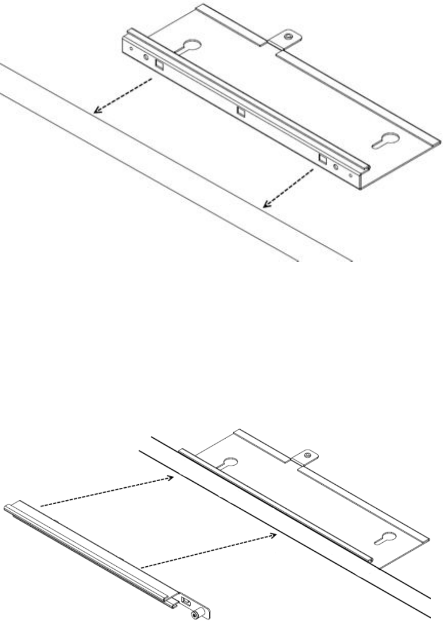
4. Montez le petit support croisé sur le grand support et serrez les deux éléments
ensemble sur la grille. Le petit support est doté de languettes dans lesquelles
s'insèrent les encoches du grand support. Ainsi, les deux éléments glissent
simultanément et sont maintenus l'un contre l'autre. Une fois cette action effectuée,
les deux supports sont resserrés sur la grille de plafond. Lorsque les deux moitiés
du support coulissent correctement l'une contre l'autre, les filets du grand support
doivent s'insérer dans la fixation captive du petit support. Utilisez un tournevis pour
serrer la fixation captive. Il est indispensable de fixer les deux supports de cette
manière afin d'éviter qu'ils ne se détachent l'un de l'autre. Serrez solidement la vis
de la fixation captive.
Installation du point d'accès 8120 WLAN avec antenne externe au plafond
Avaya WLAN 8100 Regulatory Information - WLAN AP 8120 with External Antenna October 2011 53
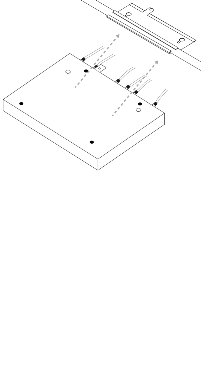
5. Fixez le point d'accès au support. Alignez les languettes de fixation du point d'accès
avec les encoches en trous de serrure du support de la grille de plafond, puis faites
glisser le point d'accès sur le dispositif de support de la grille de plafond avec soin.
Si le point d'accès et le système de support sont correctement rattachés, il doit être
possible d'insérer la vis captive du point d'accès dans la languette filetée du support
de la grille de plafond.
6. Fixez les antennes externes au mur en respectant la distance spécifiée par rapport
au point d'accès.
Si vous installez des antennes Laird avec fixation articulée, fixez les antennes à un
support ou à une surface verticale à l'aide du système de fixation articulé et des
boulons de fixation.
Antennes Laird avec flèches indiquant les 2 possibilités d'installation :
support (gauche) et fixation murale (droite)
Français
54 Avaya WLAN 8100 Regulatory Information - WLAN AP 8120 with External Antenna October 2011
Comments? infodev@avaya.com
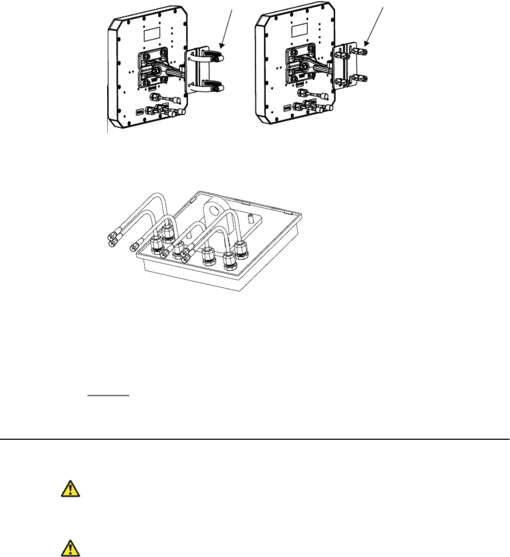
Pour installer des antennes Tyco, fixez les supports de montage au mur. Installez
ensuite les antennes sur ces supports de montage.
Antenne Tyco avec câbles raccordés
7. Assurez-vous que les antennes sont correctement fixées au plafond (ou au support
ou à la surface verticale, en cas d'installation d'antenne Laird).
8. Raccordez les câbles d'antenne au point d'accès.
9. Effectuez les raccordements électriques et remettez les dalles de plafond en
place.
Messages de sécurité
Caution:
Les radios des points d'accès 8120 WLAN avec antenne externe d'Avaya sont désactivées
par défaut et peuvent uniquement être activées par un administrateur système.
Warning:
Cette situation ou condition peut provoquer des blessures.
Messages de sécurité
Avaya WLAN 8100 Regulatory Information - WLAN AP 8120 with External Antenna October 2011 55

Warning:
Tension élevée. Cette situation ou condition peut provoquer des blessures dues à un choc
électrique.
Warning:
Seul le personnel de service qualifié est autorisé à effectuer l'installation. Lisez et suivez
l'ensemble des avertissements et instructions figurant sur le produit ou fournis dans la
documentation.
Warning:
Installez l'appareil en veillant à conserver une distance d'au moins 24,9 cm entre les
éléments rayonnants et les personnes. Cet avertissement de sécurité est conforme aux
limites d'exposition définies par la norme FCC relative aux fréquences radio.
Warning:
N'utilisez pas ce point d'accès à proximité de détonateurs non blindés ou dans d'autres
environnements où des risques d'explosion existent, sauf si l'appareil a été modifié pour
une telle utilisation par une personne qualifiée.
Warning:
Ne touchez pas et ne déplacez pas le point d'accès lorsque les antennes sont en cours de
transmission ou de réception.
Warning:
Avant d'utiliser un périphérique sans fil sur un site dangereux, consultez les réglementations
locales et nationales et interrogez les responsables de la sécurité du site afin de connaître
les contraintes d'utilisation.
Français
56 Avaya WLAN 8100 Regulatory Information - WLAN AP 8120 with External Antenna October 2011
Comments? infodev@avaya.com

Chapter 7: Português do Brasil
Use os seguintes procedimentos e informações ao instalar os pontos de acesso do Avaya WLAN AP
8120 com antena externa.
Requisitos de cabo
As portas Ethernet no ponto de acesso não podem aceitar um cabo CAT-5 com um
revestimento irregular como mostrado abaixo. O conector RJ-45 do cabo não se ajustará
adequadamente ao receptáculo no ponto de acesso. Em vez disso, use um cabo CAT-5 com
um revestimento uniforme.
Montando o WLAN AP 8120 com antena externa em uma
parede
O WLAN AP 8120 com antena externa é instalado de forma similar ao WLAN AP 8120. Além
da instalação do ponto de acesso em si, com o WLAN AP 8120 com antena externa, você
também deve montar as antenas adjacentes. Você pode montar o WLAN AP 8120 com antena
externa em uma parede usando fixadores.
Planeje sua instalação de modo a permitir que se instalem o ponto de acesso e as antenas.
Verifique se o comprimento do cabo permite a conexão do ponto de acesso às antenas. Cada
antena é fornecida com 3 cabos permanentes pré-instalados de 90 cm. Se a distância de
instalação for maior que o comprimento dos cabos originais, você pode usar cabos de
extensão adicionais de 3 m.
Avaya WLAN 8100 Regulatory Information - WLAN AP 8120 with External Antenna October 2011 57
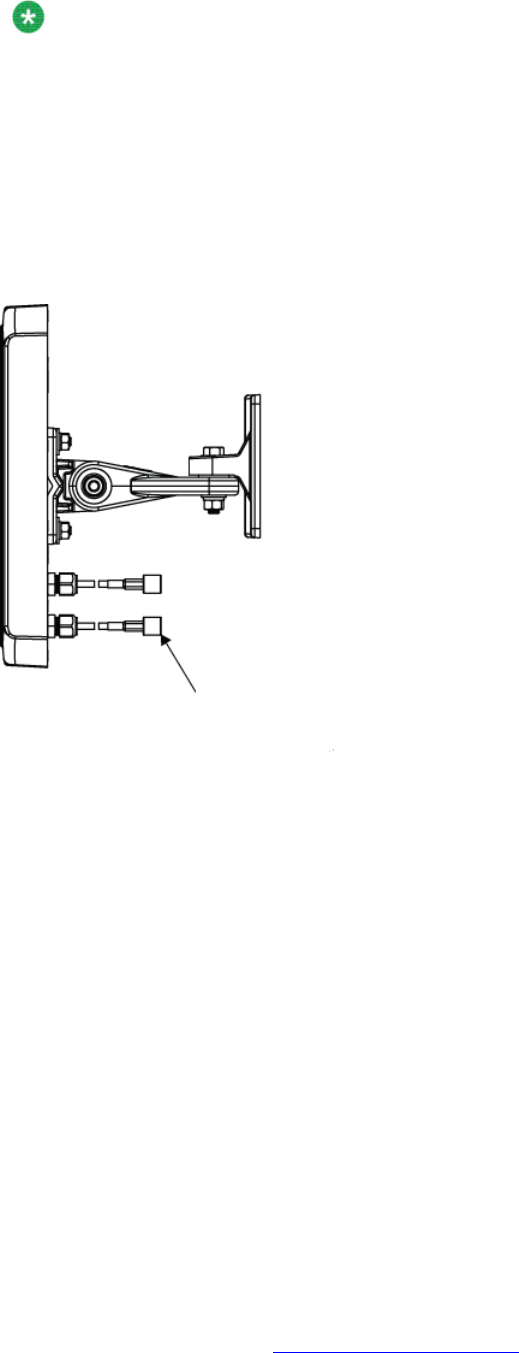
Note:
A montagem da antena externa no WLAN AP 8120 com antena externa é completada por
meio dos conectores de polaridade reversa SMA (SMA (RP-SMA). O instalador deve aplicar
a força de torção adequada ao conector usando uma chave de torque de 5/16 polegadas
que seja ajustada em 3 a 5 in-lbf (0,3 a 0,6 Nm) para conectores de latão, e 7 a 10 in-lbf
(0,8 a 1,1 Nm) para conectores de aço inoxidável. No lado do cabo do conjunto de
conectores também há uma área plana para que você possa usar uma segunda chave que
tem por função evitar que o cabo gire e danifique suas conexões. A Avaya também
recomenda a remoção de fragmentos das superfícies internas antes de conectar os
cabos.
Antena Laird com seta mostrando conector de polaridade reversa
O suporte de montagem foi projetado para usar fixadores com diâmetros de seção
aparafusados entre 3,5 mm e 4,5 mm. Se os fixadores tiverem diâmetros aparafusados
maiores de 3,5 mm, somente os dois furos marcados "A" poderão ser usados. Se os fixadores
tiverem diâmetros menores de 3,5 mm, os furos marcados "A" e "B" poderão ser usados.
Todos os fixadores de parede devem ter um diâmetro de cabeça menor de 10 mm ou não será
possível instalar o suporte de montagem sobre eles.
Execute o seguinte procedimento para instalar um ponto de acesso LAN sem fio em uma
parede:
Procedure
1. Localize a posição apropriada dos fixadores. Os fixadores devem ficar distantes
aproximadamente 95 mm horizontalmente e 80 mm verticalmente.
Português do Brasil
58 Avaya WLAN 8100 Regulatory Information - WLAN AP 8120 with External Antenna October 2011
Comments? infodev@avaya.com
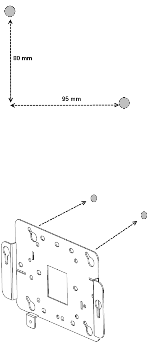
O suporte de parede foi projetado para usar um mínimo de 2 fixadores e um máximo
de 4.
2. Instale os parafusos nos fixadores, mas não os ajuste completamente. Deixe uma
folga de pelo menos 2 mm entre a cabeça do parafuso e a parede.
3. Deslize o suporte de parede sobre as cabeças dos parafusos e escorregue-o para
a direita, voltado para a parede.
4. Aperte os parafusos para segurar com firmeza o suporte de montagem contra a
parede.
5. Alinhe as presilhas de montagem na parte inferior do invólucro de metal do ponto
de acesso com os slots do suporte de montagem orientados verticalmente.
Montando o WLAN AP 8120 com antena externa em uma parede
Avaya WLAN 8100 Regulatory Information - WLAN AP 8120 with External Antenna October 2011 59

6. Permita que os pontos de acesso passem pelos slots, assegurando que as
presilhas estejam fixadas na parte inferior do slot.
7. Prenda o ponto de acesso ao suporte de montagem e ajuste os parafusos.
8. Verifique se os pontos de acesso estão fixos no suporte e na parede.
9. Monte as antenas externas na parede dentro da distância especificada do ponto
de acesso.
Se estiver instalando antenas Laird, você poderá montá-las em um mastro ou em
uma superfície vertical (parede) usando o suporte articulado e parafusos do
suporte.
Antenas Laird com setas mostrando as opções de mastro (esquerda) e
suporte de parede (direita)
Se você estiver instalando antenas TYCO, prenda os suportes de montagem à
parede e as antenas aos suportes de montagem.
Português do Brasil
60 Avaya WLAN 8100 Regulatory Information - WLAN AP 8120 with External Antenna October 2011
Comments? infodev@avaya.com
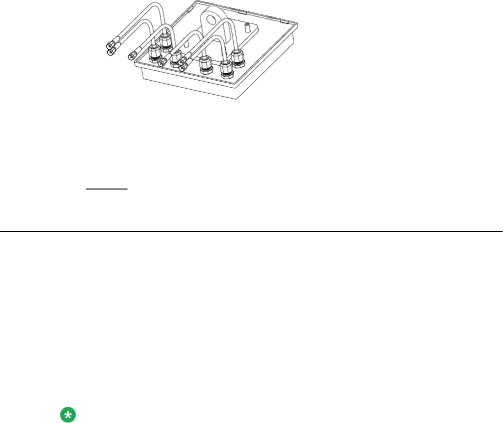
Antena TYCO mostrando cabos anexados
10. Verifique se as antenas estão firmemente montadas na parede (no mastro ou em
uma superfície vertical no caso das antenas Laird).
11. Prenda os cabos da antena ao ponto de acesso.
12. Faça as conexões elétricas.
Instalando o WLAN AP 8120 com antena externa no teto
O WLAN AP 8120 com antena externa é instalado de forma similar ao WLAN AP 8120. Além
da instalação do ponto de acesso em si, com o WLAN AP 8120 com antena externa, você
também deve montar as antenas adjacentes. Você pode montar o WLAN AP 8120 com antena
externa no teto usando um adaptador de grade de teto.
Planeje sua instalação de modo a permitir que se instalem o ponto de acesso e as antenas.
Verifique se o comprimento do cabo permite a conexão do ponto de acesso às antenas. Cada
antena é fornecida com 3 cabos permanentes pré-instalados de 90 cm. Se a distância de
instalação for maior que o comprimento dos cabos originais, você pode usar cabos de
extensão adicionais de 3 m.
Note:
A montagem da antena externa no WLAN AP 8120 com antena externa é completada por
meio dos conectores de polaridade reversa SMA (SMA (RP-SMA). O instalador deve aplicar
a força de torção adequada ao conector usando uma chave de torque de 5/16 polegadas
que seja ajustada em 3 a 5 in-lbf (0,3 a 0,6 Nm) para conectores de latão, e 7 a 10 in-lbf
(0,8 a 1,1 Nm) para conectores de aço inoxidável. No lado do cabo do conjunto de
conectores também há uma área plana para que você possa usar uma segunda chave que
tem por função evitar que o cabo gire e danifique suas conexões. A Avaya também
recomenda a remoção de fragmentos das superfícies internas antes de conectar os
cabos.
Antena Laird com seta mostrando conector de polaridade reversa
Instalando o WLAN AP 8120 com antena externa no teto
Avaya WLAN 8100 Regulatory Information - WLAN AP 8120 with External Antenna October 2011 61
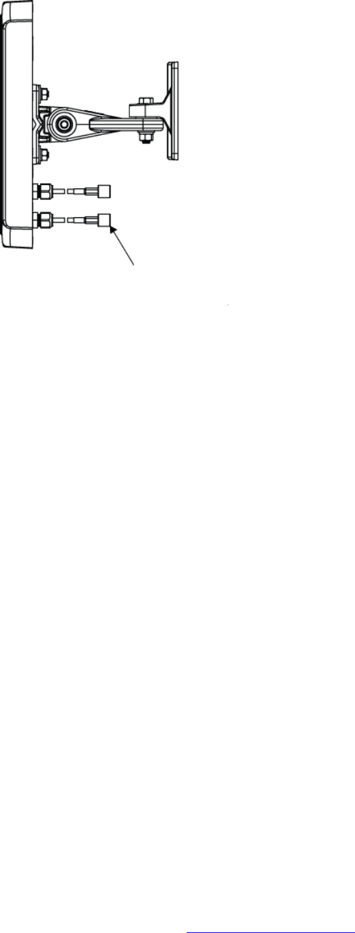
O adaptador de grade de teto vem com duas peças de travamento de suporte. A peça maior
inclui slots moldados que se encaixam às presilhas na superfície inferior do AP (painel de
acesso) e um orifício aparafusado que se encaixa a um parafuso cativo no AP. A peça menor
inclui também um prendedor cativo e pode ser orientado com relação à peça maior de duas
maneiras diferentes, de acordo com grades de teto mais amplas ou mais estreitas.
Execute o seguinte procedimento para instalar o ponto de acesso com um adaptador de grade
de teto:
Procedure
1. Garanta a segurança do ambiente de trabalho. Utilize uma escada que permita fácil
acesso ao sistema de grade de teto.
2. Identifique um local apropriado na grade onde as barras T sejam acessíveis de
forma segura e onde o revestimento do teto possa ser temporariamente suspenso
e tirado da área de trabalho. O conjunto de adaptador é para ser usado com
deslizadores de grade de seção finos, não os mais grossos, usados para atravessar
grandes extensões. Para ter espaço para mãos e ferramentas, use dois lápis ou
varetas para manter o revestimento do teto suspenso e longe da grade. Isso fará
com que você tenha acesso para ajustar os suportes à grade.
3. Instale o suporte maior na grade. Durante a instalação, preste atenção à largura
da tira da grade para determinar a orientação apropriada do suporte menor
instalado na sequência.
Português do Brasil
62 Avaya WLAN 8100 Regulatory Information - WLAN AP 8120 with External Antenna October 2011
Comments? infodev@avaya.com
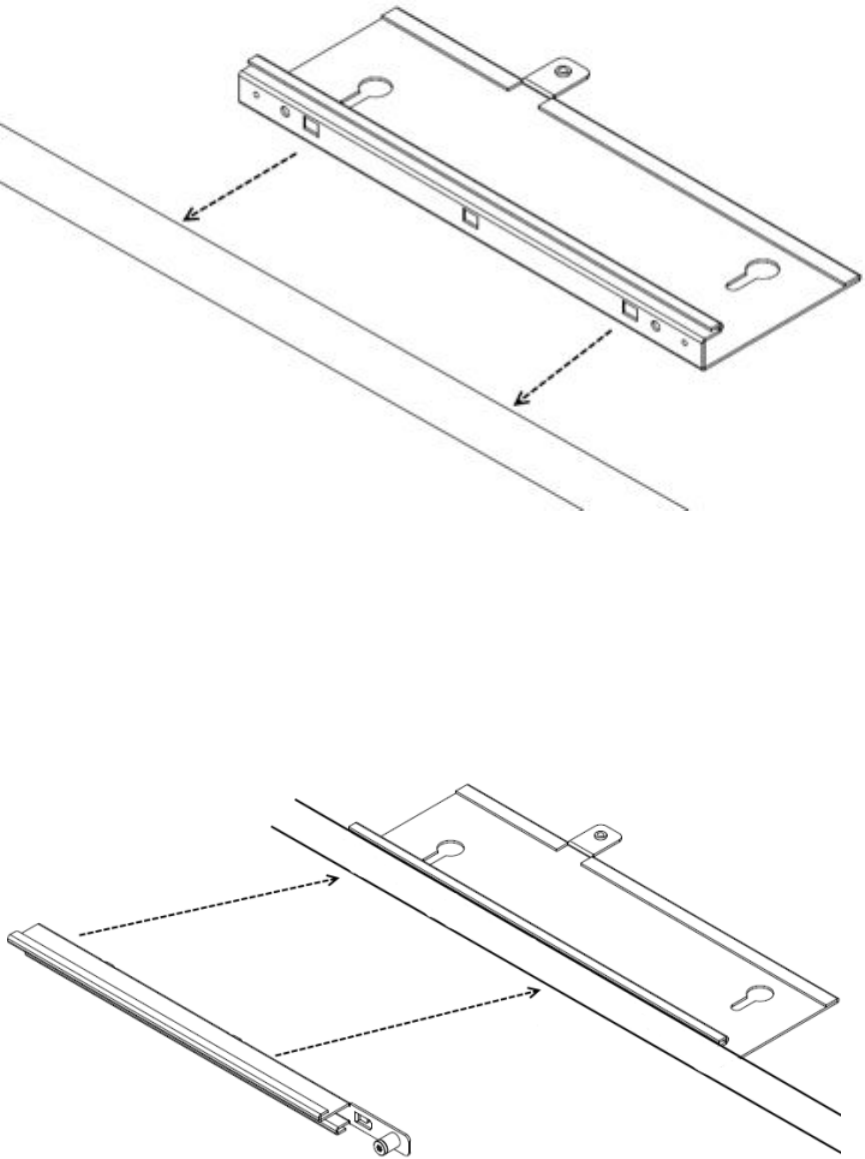
4. Instale o suporte de travamento menor sobre o suporte maior e acople as duas
peças à grade. O suporte menor contém presilhas moldadas que prendem os slots
à presilha maior. Isso permite que as duas partes deslizem juntas e se fixem uma
à outra. Quando isso é feito, os dois suportes se juntam em volta da grade de teto.
Quando as duas partes do suporte deslizam juntas corretamente, o prendedor
cativo do suporte menor deve se ajustar aos fios do suporte maior. Use uma chave
de fenda para ajustar o prendedor cativo. Prender os dois suportes dessa maneira
é essencial para evitar que se soltem. Ajuste firmemente o prendedor cativo.
5. Prenda o ponto de acesso ao suporte. Alinhe as presilhas de segurança do ponto
de acesso aos slots no suporte e deslize cuidadosamente o ponto de acesso no
Instalando o WLAN AP 8120 com antena externa no teto
Avaya WLAN 8100 Regulatory Information - WLAN AP 8120 with External Antenna October 2011 63
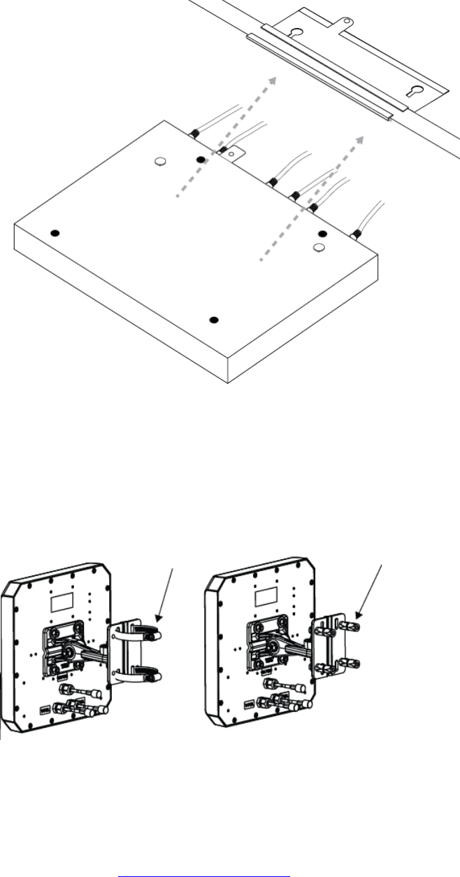
conjunto de suporte de grade de teto. Se o ponto de acesso e o conjunto de suporte
forem acoplados corretamente, o parafuso cativo dos pontos de acesso deverá se
ajustar à presilha fornecida no suporte da grade de teto.
6. Monte as antenas externas na parede dentro da distância especificada do ponto
de acesso.
Se você estiver instalando as antenas Laird com um suporte articulado, prenda as
antenas a um mastro ou a uma superfície vertical usando o suporte articulado e
parafusos do suporte.
Antenas Laird com setas mostrando as opções de mastro (esquerda) e
suporte de parede (direita)
Se você estiver instalando antenas TYCO, prenda os suportes de montagem à
parede e as antenas aos suportes de montagem.
Português do Brasil
64 Avaya WLAN 8100 Regulatory Information - WLAN AP 8120 with External Antenna October 2011
Comments? infodev@avaya.com
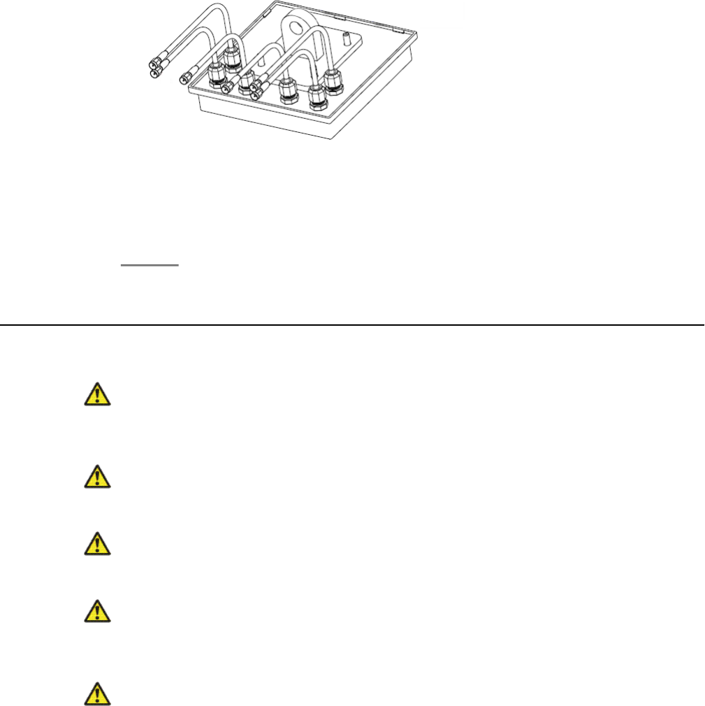
Antena TYCO mostrando cabos anexados
7. Verifique se as antenas estão firmemente montadas no teto (no mastro ou em uma
superfície vertical no caso das antenas Laird).
8. Prenda os cabos da antena ao ponto de acesso.
9. Faça as conexões elétricas e coloque o revestimento do teto no lugar.
Mensagens de segurança
Caution:
Os rádios do ponto de acesso do Avaya WLAN AP 8120 com antena externa são
desativados por padrão e só podem ser ativados pelo administrador do sistema.
Warning:
Esta situação ou condição pode causar danos.
Warning:
Alta voltagem. Esta situação ou condição pode causar dano por choque elétrico.
Warning:
Somente pessoas qualificadas devem realizar a instalação. Leia e siga os avisos e as
instruções de atenção indicados no produto ou incluídos na documentação.
Warning:
Instale este dispositivo de forma a manter um mínimo de 24,9 cm (9,8 polegadas) de
distância entre os elementos de radiação e todas as pessoas. Este aviso de segurança está
de acordo com os limites de exposição à frequência de rádio da FCC.
Mensagens de segurança
Avaya WLAN 8100 Regulatory Information - WLAN AP 8120 with External Antenna October 2011 65

Warning:
Não opere o ponto de acesso próximo a pontos de sobrecarga desprotegidos nem em outro
ambiente com risco de explosão a menos que o dispositivo tenha sido modificado para tal
uso por pessoal qualificado.
Warning:
Não toque nem mova o ponto de acesso quando as antenas estiverem transmitindo ou
recebendo.
Warning:
Antes de usar um dispositivo sem fio em um local perigoso, consulte os códigos locais,
nacionais e os responsáveis pela segurança do local para obter informações sobre
restrições de uso.
Português do Brasil
66 Avaya WLAN 8100 Regulatory Information - WLAN AP 8120 with External Antenna October 2011
Comments? infodev@avaya.com
Avaya WLAN 8100 Regulatory Information - WLAN AP 8120 with External Antenna October 2011 67
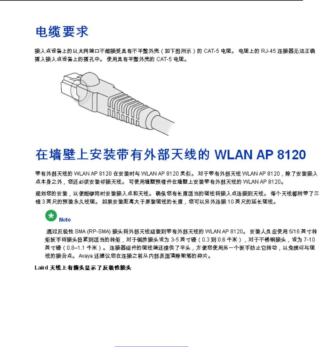
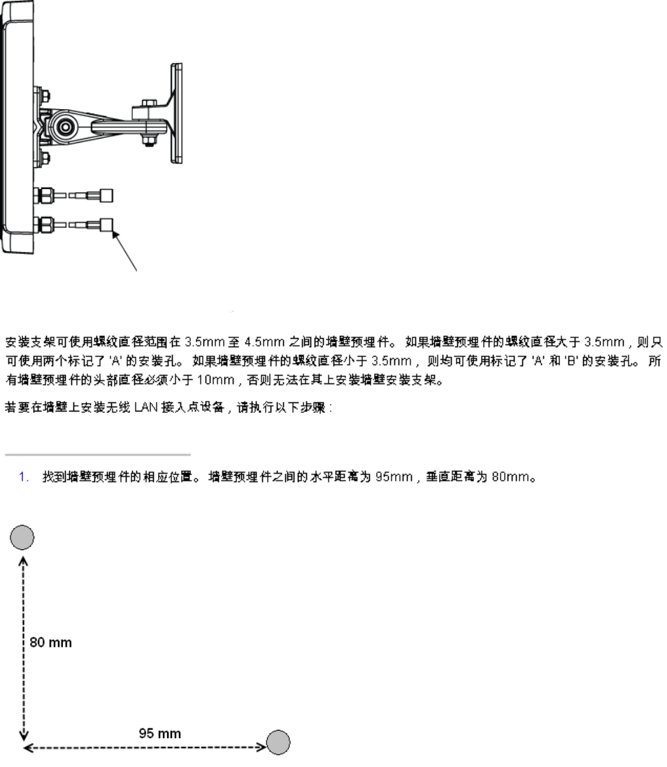
Chinese
Avaya WLAN 8100 Regulatory Information - WLAN AP 8120 with External Antenna October 2011 69
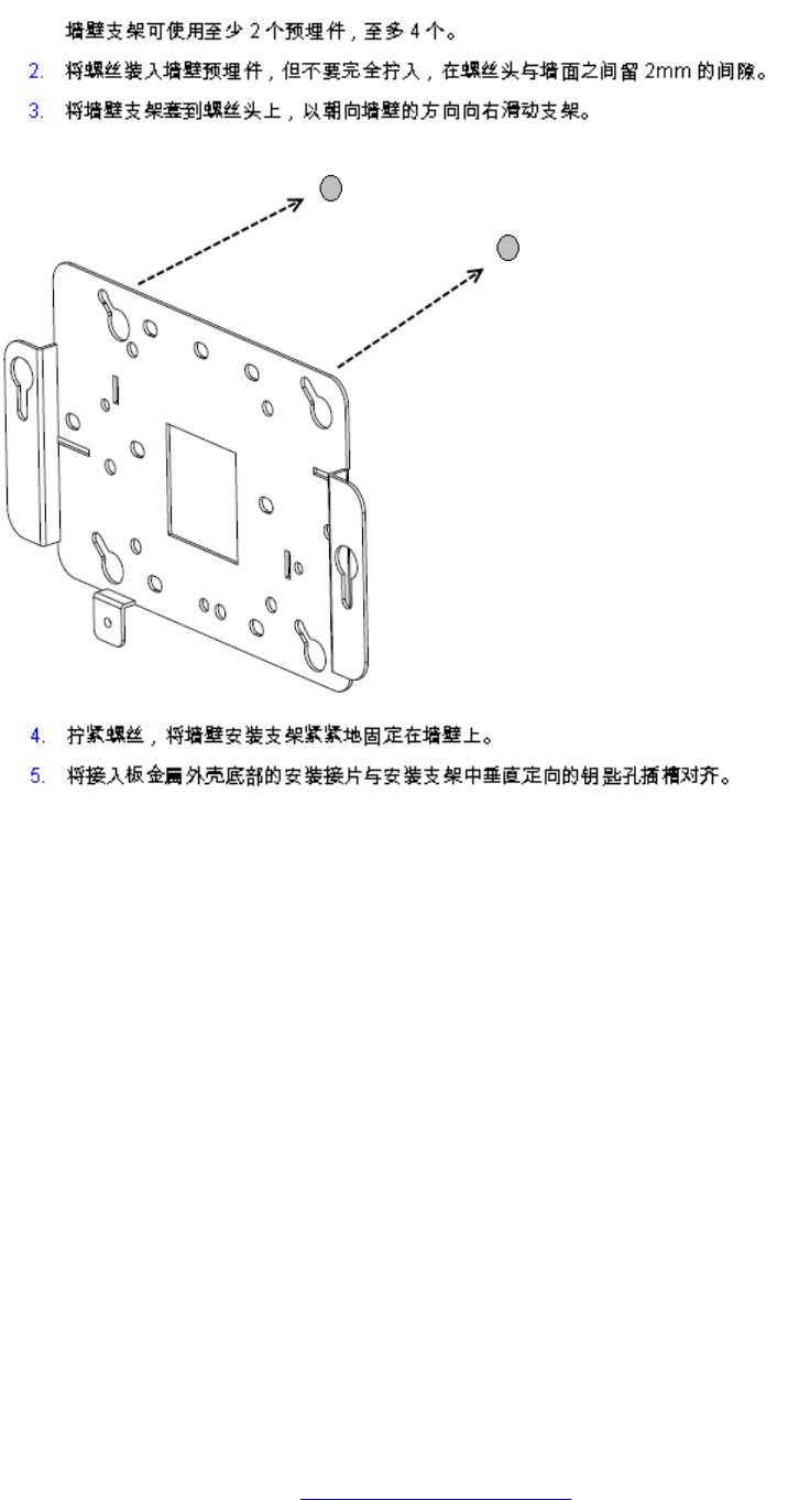
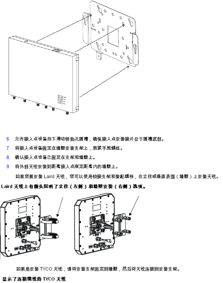
Chinese
Avaya WLAN 8100 Regulatory Information - WLAN AP 8120 with External Antenna October 2011 71
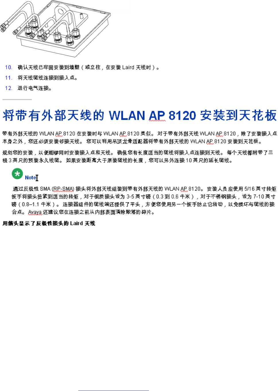
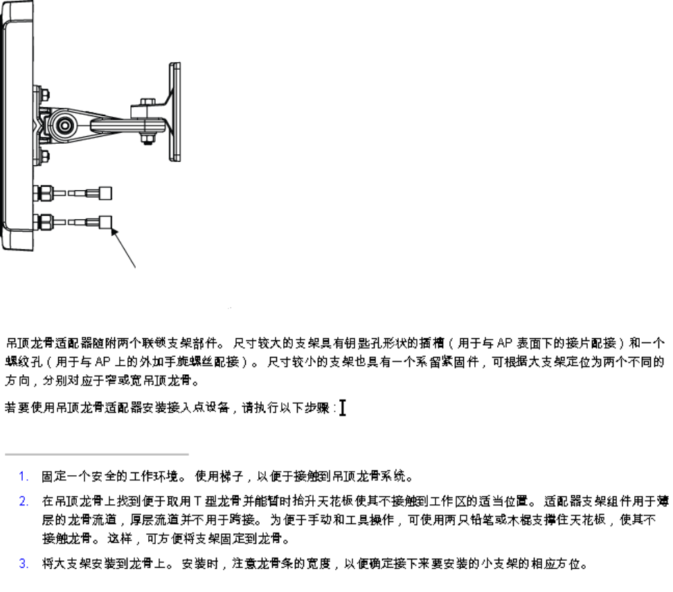
Chinese
Avaya WLAN 8100 Regulatory Information - WLAN AP 8120 with External Antenna October 2011 73
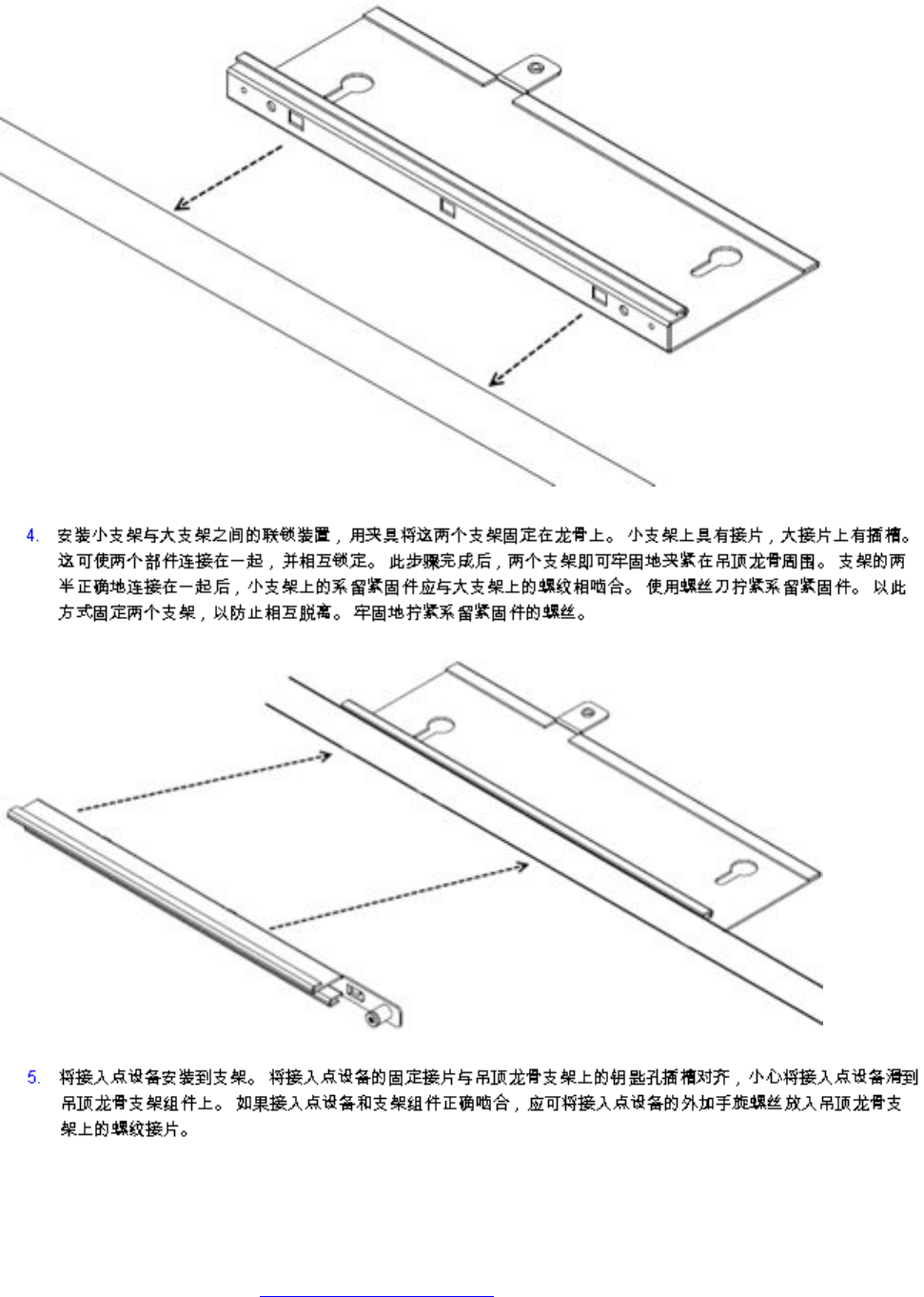
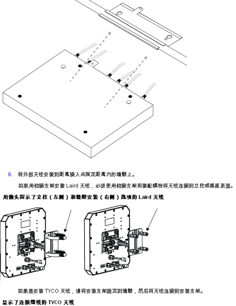
Chinese
Avaya WLAN 8100 Regulatory Information - WLAN AP 8120 with External Antenna October 2011 75
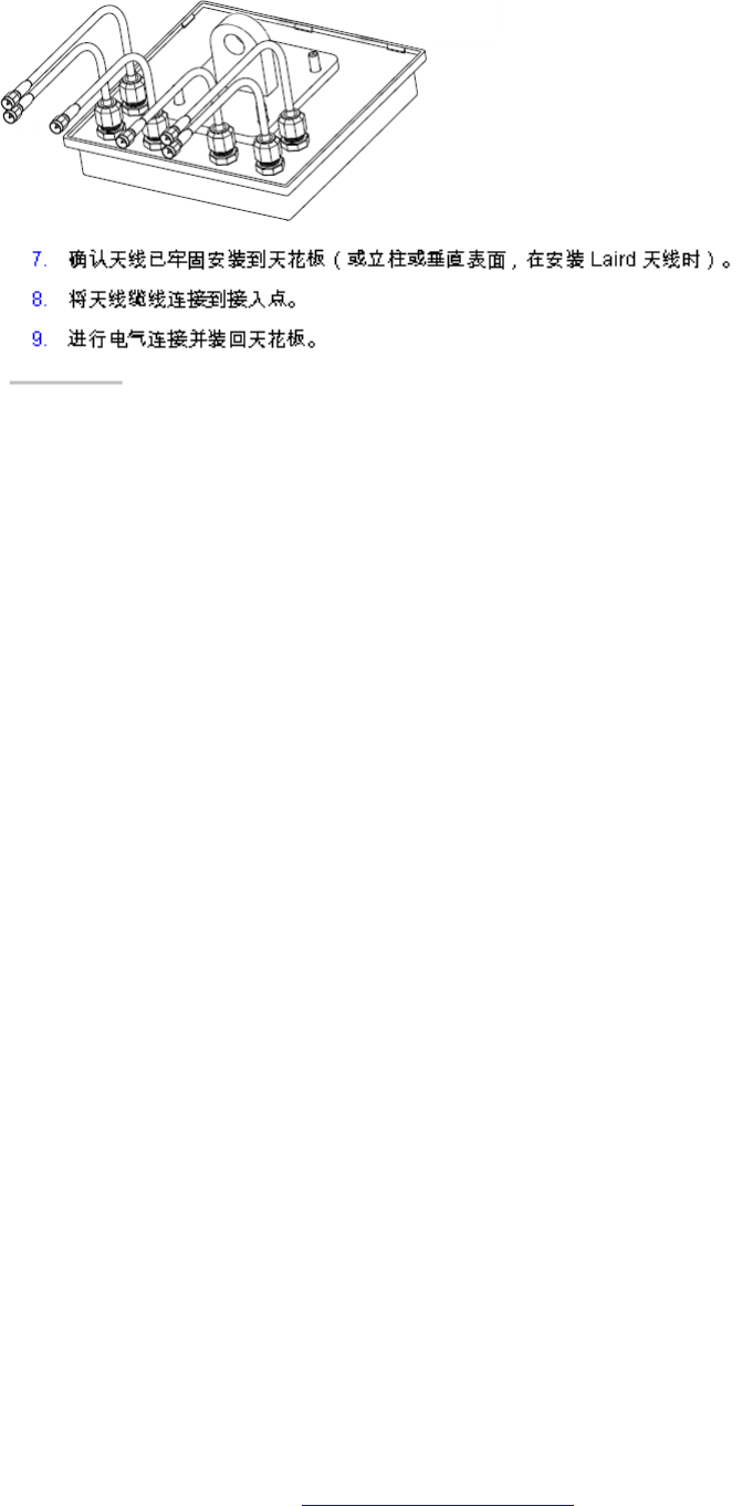
Chinese
Avaya WLAN 8100 Regulatory Information - WLAN AP 8120 with External Antenna October 2011 77
