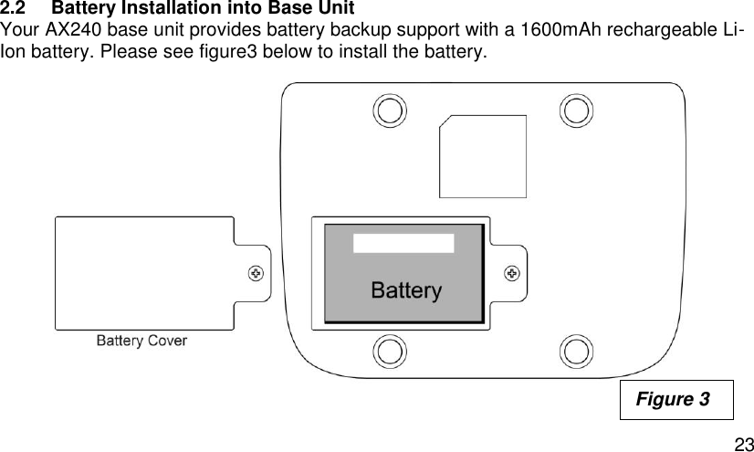
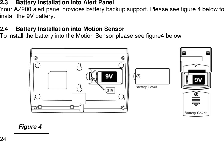
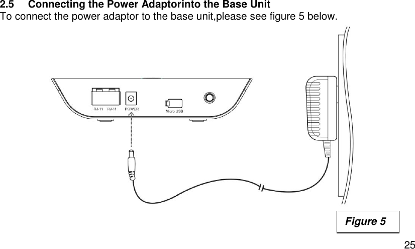
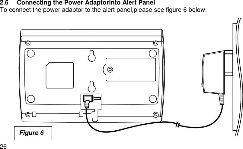
Axesstel AX240 CDMA Fixed Wireless Terminal With Smart Security Alert User Manual
Axesstel Inc CDMA Fixed Wireless Terminal With Smart Security Alert
UserManual.wiki
>
Axesstel
>
AX240 User Manual
User Manual
Navigation menu
Upload a User Manual
Namespaces
Wiki Guide
HTML
PDF
Info
Views
User Manual
Discussion / Help
Navigation
![3 AXESSTEL ALERT PRODUCTS CONSUMER WARRANTY AND LIMITATION OF LIABILITY THE AXESSTEL ALERT PRODUCT THAT YOU HAVE PURCHASED, WHEN PROPERLY INSTALLED, CAN BE USED TO DETECT MOTION IN A SPECIFIED AREA AND PROVIDE AN ALERT TO TELEPHONES OR PERSONAL DIGITAL ASSISTANTS THAT YOU SPECIFY. THE PRODUCT IS DESIGNED SOLELY TO PROVIDE AN ALERT. IT DOES NOT PROVIDE SECURITY, OR PREVENT INTRUSION, THEFT OR CRIME. THE PRODUCT IS NOT A SECURITY SERVICE, ALERTS ARE SENT ONLY TO THE DEVICES YOU SPECIFY. THEY ARE NOT MONITORED BY AXESSTEL, THE TELEPHONE COMPANY, LAW ENFORCEMENT OR OTHER AGENCIES. ALERTS ARE SENT OVER THE PUBLIC WIRELESS TELEPHONE NETWORK. INTERRUPTION OF TELEPHONE SERVICE WILL PREVENT TRANSMISSION OF ALERTS. LIMITED WARRANTY.FOR PERIOD OF [APPLICABLE WARRANTY PERIOD],AXESSTEL WARRANTS THAT THE ALERT PRODUCT SHALL (I) BE FREE FROM DEFECTS IN DESIGN, MATERIALS OR WORKMANSHIP, (II) CONFORM TO ITS PRODUCT SPECIFICATIONS AND (III) BE COMPLIANT WITH ITS WIRELESS COMMUNICATION STANDARD (CDMA 1X, EVDO, GSM, GPRS AND EDGE, AS APPLICABLE). FOR ANY PRODUCTS THAT FAIL TO MEET THE FOREGOING WARRANTY, AXESSTEL, SHALL REPAIR OR REPLACE SUCH PRODUCTS, IN ITS DISCRETION, SO THAT ANY DEFECTIVE PRODUCT OR ANY REPLACEMENT PRODUCT SHALL CONFORM TO THE WARRANTY. IF AXESSTEL CANNOT CURE ANY DEFECT ON COMMERCIALLY REASONABLE TERMS, AXESSTEL SHALL REFUND THE VALUE OF THE NON-CONFORMING PRODUCT WITHIN FORTY- FIVE (45)](https://usermanual.wiki/Axesstel/AX240/User-Guide-2059941-Page-4.png)
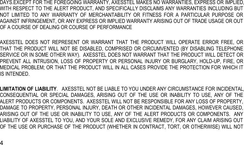
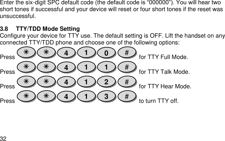
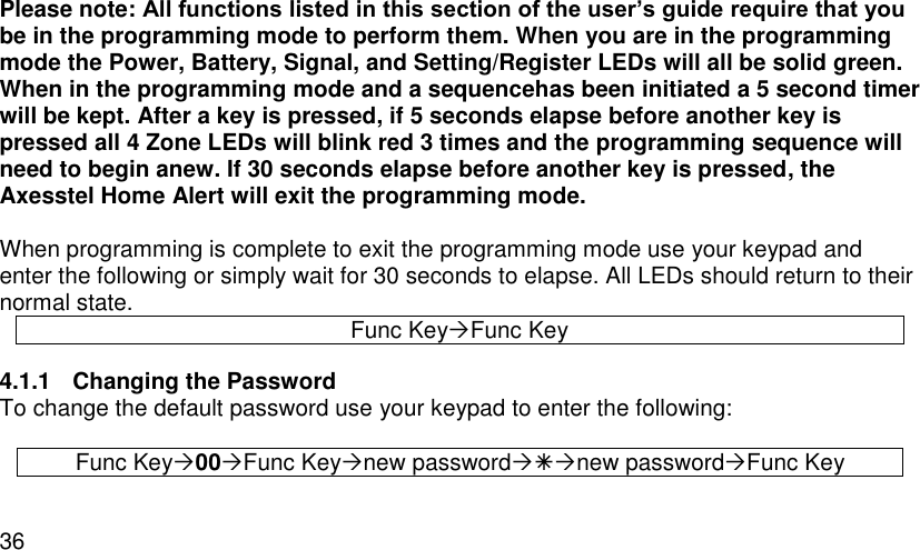

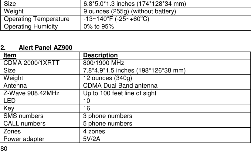
![76 Compatible Devices: Z-Wave devices may vary; follow the instructions in the User’s Guide for your specific device when adding and deleting devicesinto the Z-Wave network. Not all features are supported for off-the-shelf Z-Wave devices. Basic Z-Wave Functions: Adding 3rd party vendor Z-Wave device; please refer to the instructions for the Z-Wave device that you are installing. Inclusion: Add a Z-Wave enabled device On AX140 enter the command [#password75 Func-Key]; on other Z-Wave device [Press switch to enter inclusion mode (see manufactures instructions for device)] Exclusion: Remove a Z-Wave enabled device. On AX140 enter the command [#password70Func-Key]; on other Z-Wave device [Press switch to enter inclusion mode (see manufactures instructions for device)]](https://usermanual.wiki/Axesstel/AX240/User-Guide-2059941-Page-77.png)
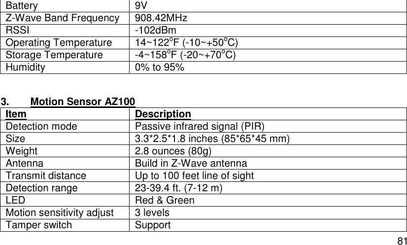
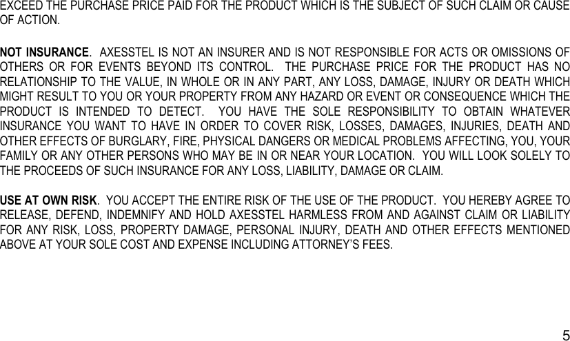
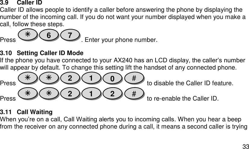
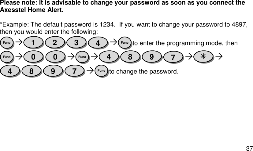
![77 Association: After inclusion, define the relationship between devices (primary/secondary), by specifying one as primary to control the other secondary device. On AX140 enter the command [#password81Group IDFunc-Key]; on the other Z-Wave sensor [Click the button in secondary sensor first then in the primarysensor; this will add the primary sensor to secondary sensor association group(see manufactures instructions for device)] If no Group ID is found, user can specify (example “1”). To Remove the Association (primary sensor from secondary sensor): On AX140 enter the command [#password82Group IDFunc-Key]. Manual Association to the AX140 Controller: On AX140 enter the command [#password83Group IDFunc-Key]; Click the Z-Wave button on the primary sensor will add it to Controller Association Group. To Remove the primary sensor Association Group: On AX140 enter the command [#password84Group IDFunc-Key]](https://usermanual.wiki/Axesstel/AX240/User-Guide-2059941-Page-78.png)
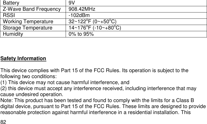
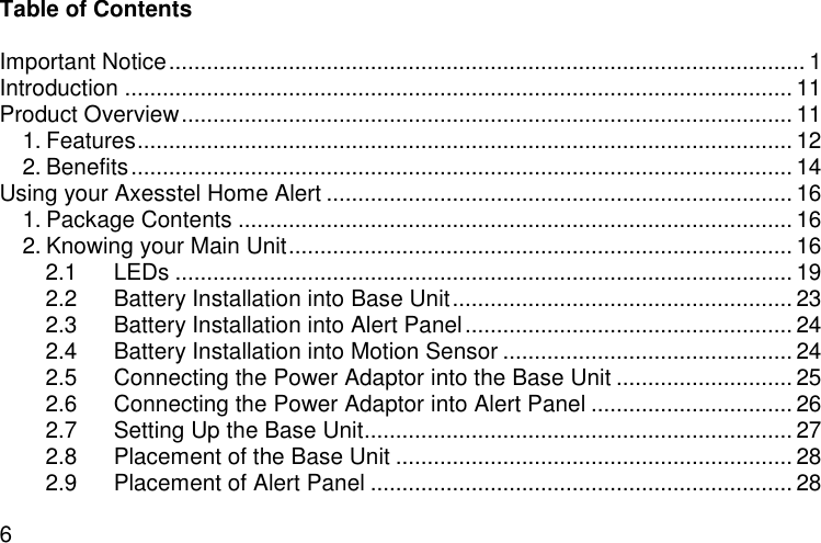
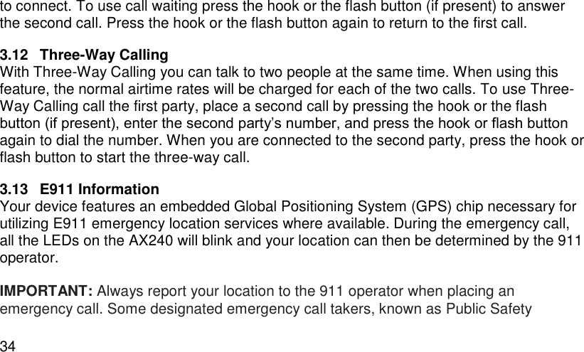
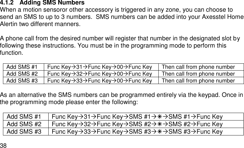
![78 Learn Mode: How to make the AX140 become a secondary controller. On AX140 enter the command [#password85Func-Key]. Click Z-Wave button on the primary controller. Controller Shift: How to go back/shift back to primary controller. On AX140 enter the command [#password86Func-Key]. Click Z-Wave button on the secondary controller.](https://usermanual.wiki/Axesstel/AX240/User-Guide-2059941-Page-79.png)