Axesstel AX240 CDMA Fixed Wireless Terminal With Smart Security Alert User Manual
Axesstel Inc CDMA Fixed Wireless Terminal With Smart Security Alert
Axesstel >
User Manual
0

1
Important Notice
Due to the nature of wireless communications, transmission and reception of data can
never be guaranteed. Data may be delayed, corrupted (i.e. have errors) or be totally lost.
Although significant delays or losses of data are rare when wireless devices are used in a
normal manner with a well-constructed network, the device should not be used in
situations where failure to transmit or receive data could result in damage of any kind to
the user or any other party, including but not limited to personal injury, death or loss of
property. Axesstel accepts no responsibility for damages of any kind resulting from delays
or errors in data transmitted or received using the Axessteldevice or for failure of the
Axesstel device to transmit or receive such data.
2
Safety Precautions
Only use the supplied power adaptor, and do not use the power adaptor in
temperatures over 40oC, and only use in a dry location
Only use 9V batteries in the main unit and the motion sensors, as there is a risk
of explosion if an incorrect battery type is used
Please dispose of any used 9V batteries at a proper facility
Do not operate the device:
o In areas where blasting is in progress
o Where explosive atmospheres may be present
o Near medical equipment
o Near life support equipment or any equipment that may be susceptible to
any form of radio interference. In such areas, the device MUST BE
POWERED OFF. The Axesstel device can transmit signals that could
interfere with this equipment.
3
AXESSTEL ALERT PRODUCTS
CONSUMER WARRANTY AND LIMITATION OF LIABILITY
THE AXESSTEL ALERT PRODUCT THAT YOU HAVE PURCHASED, WHEN PROPERLY INSTALLED, CAN BE USED
TO DETECT MOTION IN A SPECIFIED AREA AND PROVIDE AN ALERT TO TELEPHONES OR PERSONAL DIGITAL
ASSISTANTS THAT YOU SPECIFY. THE PRODUCT IS DESIGNED SOLELY TO PROVIDE AN ALERT. IT DOES
NOT PROVIDE SECURITY, OR PREVENT INTRUSION, THEFT OR CRIME.
THE PRODUCT IS NOT A SECURITY SERVICE, ALERTS ARE SENT ONLY TO THE DEVICES YOU SPECIFY. THEY
ARE NOT MONITORED BY AXESSTEL, THE TELEPHONE COMPANY, LAW ENFORCEMENT OR OTHER AGENCIES.
ALERTS ARE SENT OVER THE PUBLIC WIRELESS TELEPHONE NETWORK. INTERRUPTION OF TELEPHONE
SERVICE WILL PREVENT TRANSMISSION OF ALERTS.
LIMITED WARRANTY.FOR PERIOD OF [APPLICABLE WARRANTY PERIOD],AXESSTEL WARRANTS THAT THE
ALERT PRODUCT SHALL (I) BE FREE FROM DEFECTS IN DESIGN, MATERIALS OR WORKMANSHIP, (II)
CONFORM TO ITS PRODUCT SPECIFICATIONS AND (III) BE COMPLIANT WITH ITS WIRELESS COMMUNICATION
STANDARD (CDMA 1X, EVDO, GSM, GPRS AND EDGE, AS APPLICABLE). FOR ANY PRODUCTS THAT FAIL TO
MEET THE FOREGOING WARRANTY, AXESSTEL, SHALL REPAIR OR REPLACE SUCH PRODUCTS, IN ITS
DISCRETION, SO THAT ANY DEFECTIVE PRODUCT OR ANY REPLACEMENT PRODUCT SHALL CONFORM TO
THE WARRANTY. IF AXESSTEL CANNOT CURE ANY DEFECT ON COMMERCIALLY REASONABLE TERMS,
AXESSTEL SHALL REFUND THE VALUE OF THE NON-CONFORMING PRODUCT WITHIN FORTY- FIVE (45)
4
DAYS.EXCEPT FOR THE FOREGOING WARRANTY, AXESSTEL MAKES NO WARRANTIES, EXPRESS OR IMPLIED,
WITH RESPECT TO THE ALERT PRODUCT, AND SPECIFICALLY DISCLAIMS ANY WARRANTIES INCLUDING BUT
NOT LIMITED TO ANY WARRANTY OF MERCHANTABILITY OR FITNESS FOR A PARTICULAR PURPOSE OR
AGAINST INFRINGEMENT, OR ANY EXPRESS OR IMPLIED WARRANTY ARISING OUT OF TRADE USAGE OR OUT
OF A COURSE OF DEALING OR COURSE OF PERFORMANCE
AXESSTEL DOES NOT REPRESENT OR WARRANT THAT THE PRODUCT WILL OPERATE ERROR FREE, OR
THAT THE PRODUCT WILL NOT BE DISABLED, COMPRISED OR CIRCUMVENTED (BY DISABLING TELEPHONE
SERVICE OR IN SOME OTHER WAY). AXESSTEL DOES NOT WARRANT THAT THE PRODUCT WILL DETECT OR
PREVENT ALL INTRUSION, LOSS OF PROPERTY OR PERSONAL INJURY OR BURGLARY, HOLD-UP, FIRE, OR
MEDICAL PROBLEM; OR THAT THE PRODUCT WILL IN ALL CASES PROVIDE THE PROTECTION FOR WHICH IT
IS INTENDED.
LIMITATION OF LIABILITY. AXESSTEL NOT BE LIABLE TO YOU UNDER ANY CIRCUMSTANCE FOR INCIDENTAL,
CONSEQUENTIAL OR SPECIAL DAMAGES, ARISING OUT OF THE USE OR INABILITY TO USE, ANY OF THE
ALERT PRODUCTS OR COMPONENTS. AXESSTEL WILL NOT BE RESPONSIBLE FOR ANY LOSS OF PROPERTY,
DAMAGE TO PROPERTY, PERSONAL INJURY, DEATH OR OTHER INCIDENTAL DAMAGES, HOWEVER CAUSED,
ARISING OUT OF THE USE OR INABILITY TO USE, ANY OF THE ALERT PRODUCTS OR COMPONENTS. ANY
LIABILITY OF AXESSTEL TO YOU, AND YOUR SOLE AND EXCLUSIVE REMEDY, FOR ANY CLAIM ARISING OUT
OF THE USE OR PURCHASE OF THE PRODUCT (WHETHER IN CONTRACT, TORT, OR OTHERWISE) WILL NOT
5
EXCEED THE PURCHASE PRICE PAID FOR THE PRODUCT WHICH IS THE SUBJECT OF SUCH CLAIM OR CAUSE
OF ACTION.
NOT INSURANCE. AXESSTEL IS NOT AN INSURER AND IS NOT RESPONSIBLE FOR ACTS OR OMISSIONS OF
OTHERS OR FOR EVENTS BEYOND ITS CONTROL. THE PURCHASE PRICE FOR THE PRODUCT HAS NO
RELATIONSHIP TO THE VALUE, IN WHOLE OR IN ANY PART, ANY LOSS, DAMAGE, INJURY OR DEATH WHICH
MIGHT RESULT TO YOU OR YOUR PROPERTY FROM ANY HAZARD OR EVENT OR CONSEQUENCE WHICH THE
PRODUCT IS INTENDED TO DETECT. YOU HAVE THE SOLE RESPONSIBILITY TO OBTAIN WHATEVER
INSURANCE YOU WANT TO HAVE IN ORDER TO COVER RISK, LOSSES, DAMAGES, INJURIES, DEATH AND
OTHER EFFECTS OF BURGLARY, FIRE, PHYSICAL DANGERS OR MEDICAL PROBLEMS AFFECTING, YOU, YOUR
FAMILY OR ANY OTHER PERSONS WHO MAY BE IN OR NEAR YOUR LOCATION. YOU WILL LOOK SOLELY TO
THE PROCEEDS OF SUCH INSURANCE FOR ANY LOSS, LIABILITY, DAMAGE OR CLAIM.
USE AT OWN RISK. YOU ACCEPT THE ENTIRE RISK OF THE USE OF THE PRODUCT. YOU HEREBY AGREE TO
RELEASE, DEFEND, INDEMNIFY AND HOLD AXESSTEL HARMLESS FROM AND AGAINST CLAIM OR LIABILITY
FOR ANY RISK, LOSS, PROPERTY DAMAGE, PERSONAL INJURY, DEATH AND OTHER EFFECTS MENTIONED
ABOVE AT YOUR SOLE COST AND EXPENSE INCLUDING ATTORNEY’S FEES.
6
Table of Contents
Important Notice ..................................................................................................... 1
Introduction .......................................................................................................... 11
Product Overview ................................................................................................. 11
1. Features ........................................................................................................ 12
2. Benefits ......................................................................................................... 14
Using your Axesstel Home Alert .......................................................................... 16
1. Package Contents ........................................................................................ 16
2. Knowing your Main Unit ................................................................................ 16
2.1 LEDs .................................................................................................. 19
2.2 Battery Installation into Base Unit ...................................................... 23
2.3 Battery Installation into Alert Panel .................................................... 24
2.4 Battery Installation into Motion Sensor .............................................. 24
2.5 Connecting the Power Adaptor into the Base Unit ............................ 25
2.6 Connecting the Power Adaptor into Alert Panel ................................ 26
2.7 Setting Up the Base Unit.................................................................... 27
2.8 Placement of the Base Unit ............................................................... 28
2.9 Placement of Alert Panel ................................................................... 28
7
2.10 Placement of Motion Sensor .......................................................... 28
3. Using your 200 Series as a Landline Replacement Phone .......................... 29
3.1 Power On/Off ..................................................................................... 29
3.2 Activation............................................................................................ 29
3.3 Setting Up Your Voicemail ................................................................. 30
3.4 Making Calls ...................................................................................... 30
3.5 Answering Calls ................................................................................. 31
3.6 Default Reset ..................................................................................... 31
3.7 Factory Reset ..................................................................................... 31
3.8 TTY/TDD Mode Setting ...................................................................... 32
3.9 Caller ID ............................................................................................. 33
3.10 Setting Caller ID Mode ................................................................... 33
3.11 Call Waiting .................................................................................... 33
3.12 Three-Way Calling .......................................................................... 34
3.13 E911 Information ............................................................................ 34
4. Using your 200 Series as an Alert System ................................................... 35
4.1 Programming Mode ........................................................................... 35
4.1.1 Changing the Password.............................................................. 36
4.1.2 Adding SMS Numbers ................................................................ 38
8
4.1.3 Removing SMS Numbers ........................................................... 40
4.1.4 Adding Call Numbers .................................................................. 40
4.1.5 Removing Call Numbers ............................................................. 43
4.1.6 Adding Sensors .......................................................................... 43
4.1.7 Pet Immunity ............................................................................... 46
4.1.8 Removing Sensors ..................................................................... 46
4.1.9 Adding the Key Fob .................................................................... 47
4.1.10 Adding the Panic Key Fob .......................................................... 48
4.1.11 Set Entry Mode ........................................................................... 48
4.1.12 Set Exit Mode ............................................................................. 49
4.1.13 Factory Reset ............................................................................. 50
4.1.14 Test Mode 1 – Call ...................................................................... 51
4.1.15 Test Mode 2 – SMS .................................................................... 51
4.2 Armed Mode ...................................................................................... 52
4.2.1 Armed Away ............................................................................... 52
4.2.2 Armed Away Silent ..................................................................... 53
4.2.3 Armed Stay ................................................................................. 53
4.2.4 Armed Stay Silent ....................................................................... 55
4.2.5 Remote Arming via Key Fob ....................................................... 56
9
4.2.6 Remote Arming via Smartphone App ......................................... 56
4.2.7 Continued Arming ....................................................................... 56
4.3 Disarmed Mode .................................................................................. 56
4.3.1 Disarm via Keypad ...................................................................... 57
4.3.2 Remote Disarm via Key Fob ....................................................... 57
4.3.3 Remote Disarm via Smartphone App ......................................... 57
4.4 Alarmed Mode .................................................................................... 58
4.4.1 Panic Button ............................................................................... 58
4.5 Additional Functions & Features ........................................................ 59
4.5.1 Audio Monitoring/2-Way Communication ................................... 59
4.5.2 Tamper Prevention ..................................................................... 59
4.5.3 Audible Siren .............................................................................. 59
4.5.4 Axesstel Home Alert Accessories ............................................... 60
5. AX240 Smartphone Application .................................................................... 61
5.1 AX240 App for Android ...................................................................... 61
5.2 AX240 App for iPhone ....................................................................... 62
5.3 AX240 App creating user account (Android/iOS) .............................. 62
5.4 Manage Call Numbers (Android/iOS) ................................................ 65
5.5 Manage SMS Numbers (Android/iOS) ............................................... 66
10
5.6 Delay Time (Entry/Exit ) ..................................................................... 67
5.7 Remote Arming/Disarming ................................................................. 69
5.8 Account Info/Device Status (Android/iOS) ......................................... 70
5.9 Event Log ........................................................................................... 72
Z-Wave ................................................................................................................. 73
Operating Specifications ...................................................................................... 79
1. Base Unit AX240 .......................................................................................... 79
2. Alert Panel AZ900 ......................................................................................... 80
3. Motion Sensor AZ100 ................................................................................... 81
Safety Information ................................................................................................ 82

11
Introduction
This user manual will help you place, configure and use your AX240 Alert System.
Product Overview
The AX240 Axesstel Home Alert is a fixed cellular terminal with a wireless alert system.
As a terminal, the AX240 has an RJ-11 interface for POTS phones to make and receive
phone calls as done through a landline. As a home alert, a built-in cellular modem can
send an SMS or place a phone call to a series of pre-assigned phone numbers when a
sensor is triggered. Up to 8 contacts can be notified of the alert. The arming and
disarming can be triggered by keypad input or by sending an SMS. Smartphone
applications are available on ‘Google Play’ for Android and ‘App Store’ for iOS. The
AX240 Axesstel Home Alert has LED indicators to represent the status of the product and
sensors. It is easy to set up and configure in a few simple steps. The system is
expandable to connect up to 200 sensors utilizing Z-Wave protocol. The AX240 is
powered by an AC adapter with a 1600mAh rechargeable battery backup to provide
continued functionality in the event of a power outage. This self-monitoring alert system
can provide peace of mind and security without the need for an expensive security
contract.

12
Some features described in this manual may not be supported by your service provider or
may not be available with your network account. For details of the services and accounts
available, contact your service provider.
1. Features
• Android and iOS Applications for AX240 Management
• 800MHz/1900MHz CDMA2000 1x-Advanced
• Z-Wave Short Range Wireless Protocol
• Call Alerting Numbers - Stores 5 pre-assigned numbers
• SMS Alerting Numbers - Stores 3 pre-assigned number
• Remote Arm/Disarm Capabilities via Smartphone application
• 10 Multiple LED Indicators (Alert Panel) - Power, Battery, CDMA,
Setting/Register, Active, Zone Status Indicator 1 – 4, Account
• OMA-DM HFA or OTASP Activation
• Standard Telephone Keypad with Tactile Feel
• Audible Siren for Alert Trigger
• Audible Beeper and LED Indicationfor Programming Configuration
• Panic Button for Emergency Situations
13
• Event History Log
• Silent Alarm Capability
• Low Battery Warning LED for Sensors on Base Unit
• Tamper Prevention on Alert Panel, Motion Sensor, and Window/Door
Sensors
• Z-Wave Capabilities Include Motion Sensors, Door/Window Sensors,
Keyfob, and Others
• Configure up to 200 Sensors/Motion Detectors
• Armed Away, Armed Home, and Disarm Modes
• 4 Alert Function Keys – Arm/Disarm, Stay, Panic, Function
• Store/Manage User Defined 4-Digit Passcodes
• Delayed Entry/Exit Mode
• 5 Multiple LED Indicators (Base Unit) – Power, Battery, Voicemail Waiting
Indicator, Mode, CDMA
• 2 RJ-11 Ports (Bridged) to Connect to POTS Phones
• Dial Tone and DTMF Generation
• AGPS for E911 Service Support
• Call Waiting, Call Forwarding, Three-Way Calling, and Hook Flash
• FUMO Support

14
• Automatic Sender Caller ID
• Built-in Speaker and Microphone to Monitor Surroundings
• Rechargeable 1600mAh Li-Ion Backup Battery (Base Unit)
• USB Diagnostic Port for Firmware Upgrades
2. Benefits
Wireless Alert Notification - SMS/Call Alerts if the Motion Sensor is Triggered
The AX240 Axesstel Home Alert has a built-in 1x-Advanced cellular modem that can
notify up to 8 friends and neighbors via call and SMS when motion is detected to increase
chances of a close-by responder.
Landline Phone Replacement
The AX240 has an RJ-11 interface for POTS phones to make and receive phone calls as
done through a landline. Current phone numbers can be maintained and monthly costs
can be decreased.

15
Emergency Backup Battery
An AC adaptor with a 1600mAh backup battery provides the base unit with continued
functionality in the event of a power outage. The alert panel contains an AC adaptor and
a 9V backup battery.
Remote Control Convenience
The arming and disarming of the AX240 Alert System can be triggered by keypad input or
by sending a remote SMS from one of your registered numbers. A smartphone app may
also be used from your Android or iOS smartphone.
Affordable, Easy to Setup, Configure, and Use
Setup and configuration of the AX240 Axesstel Home Alert is accomplished simply. The
base unit has 5 LED indicators and the alert panel has 10 LED indicators to represent the
product status. This reasonably priced system can be configured for use with up to 200
sensors or motion detectors. All the accessories in the box have been pre-associated with
the main unit and are ready to be used.

16
Using your Axesstel Home Alert
1. Package Contents
Standard contents may vary from carrier to carrier. The items listed below may be added
to depending upon carrier preferences.
AX240 Base Unit
AZ900 Alert Panel
Motion Sensor
Power Adaptors
Mounting Kits
User Manual/Quick Start Guide
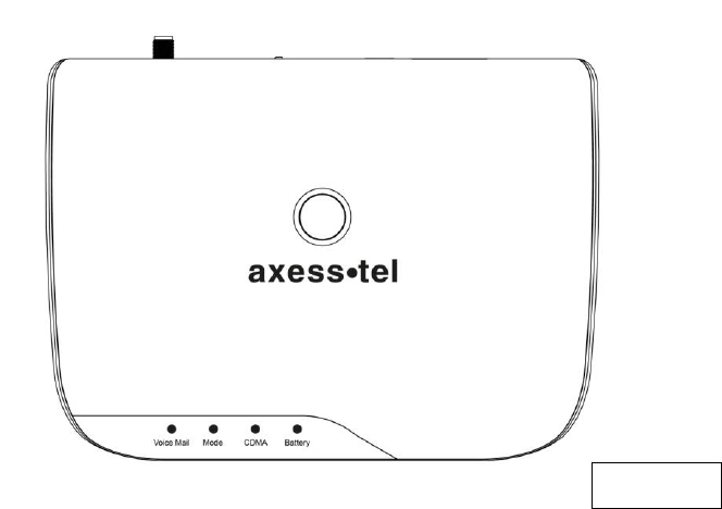
2. Knowing your Main Unit
Your Axesstel Home Alert is designed to be wall mounted, or it can simply be placed on a
shelf. All the LEDs are easily visible while the power cord will connect at the back. See
figure 1 for a depiction of the device.
17
AX240 Base Unit
Figure 1
18
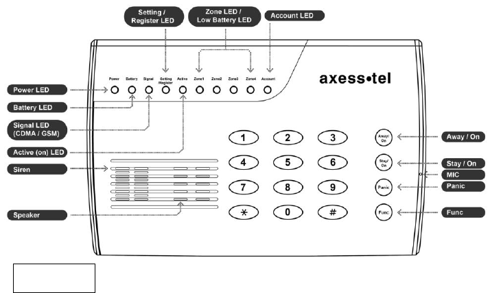
AZ900 Alert Panel
Figure 2

19
2.1 LEDs
The AX240 base unit has 5 LEDs. The functionality of the LEDs is found in the table
below.
Base Unit LED description
LED
Color
Function
Power
Green
Device is powered on
OFF
The device is powered off
Battery
Green
Battery is sole source, power above
mid-level
Blink Green
AC is sole source, battery charging
Red
Battery is sole source, voltage low
Blink Red
AC is sole source, no battery
CDMA
Green
Camped on network
Red
No CDMA coverage
Mode
Green
Incoming call
Red
Off hook
OFF
On hook
VoicemailWaitingIndicator
Red
Voicemail in the system
OFF
No new voicemail

20
E911 Call
All LEDs
Blinking
All LEDs blink during emergency call
The AZ900alert panel has 10 LEDs. The functionality of the LEDs is found in the table
below.
Alert Panel LED description
LED
Color
Function
Power
Green
Device is powered on
OFF
The device is powered off
Battery
Blink Green
Battery is good/ powered by battery
Red
Battery is low/ powered by battery
OFF
No battery in use
Signal
(CDMA/GSM)
Green
Good signal coverage
Blink Green
Mid-signal coverage
Red
Lowsignal coverage
OFF
No coverage
Setting
/Register
Green
In setting status
Blink Green
In registration status, push button in sensor to add

21
Active (On)
Red
Device is armed
OFF
Device is disarmed
Zone1
Green
Sensor is Armed
Red
Sensor Alarm detected
OFF
Sensor is Disarmed
Blink Red
Sensor Low battery warning
Zone2
Green
Sensor is Armed
Red
Sensor Alarm detected
OFF
Sensor is Disarmed
Blink Red
Sensor Low battery warning
Zone3
Green
Sensor is Armed
Red
Sensor Alarm detected
OFF
Sensor is Disarmed
Blink Red
Sensor Low battery warning
Zone4
Green
Sensor is Armed
Red
Sensor Alarm detected
OFF
Sensor is Disarmed
Blink Red
Sensor Low battery warning

22
Account (Bill)
OFF
Optional use by Network
Programming
Mode
Green
When in Programming Mode the Power, Battery,
Signal and Setting/Register LEDs will be green
Programming
Mode Exit
Blink Red
When in Programming Mode after a key is
pressed, if 5 seconds elapse before another key
is pressed all 4 Zone LEDs will blink red 3 times
and the programming sequence will need to
begin anew. If 30 seconds elapse before another
key is pressed, the Axesstel Home Alert will exit
the programming mode and all LEDs will return
to their normal state
Programming
Success
Blink Green
When in Programming Mode successful
programming
will result in all 4 Zone LEDs blinking green 1
time
Programming
Failure
Blink Red
When in Programming Mode failed programming
will result in all 4 Zone LEDs blinking red 3 times
23
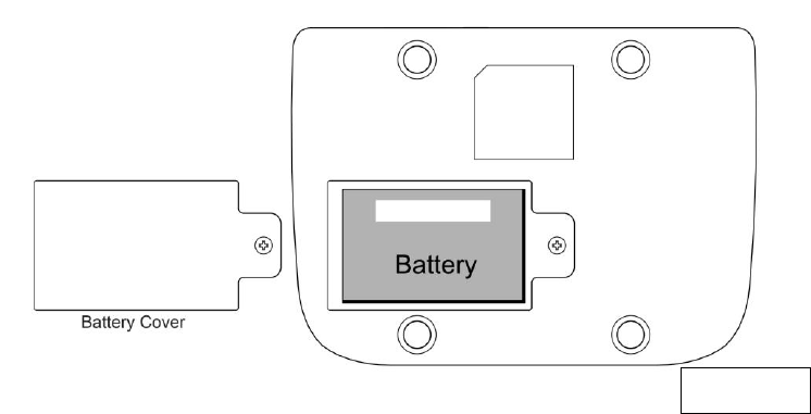
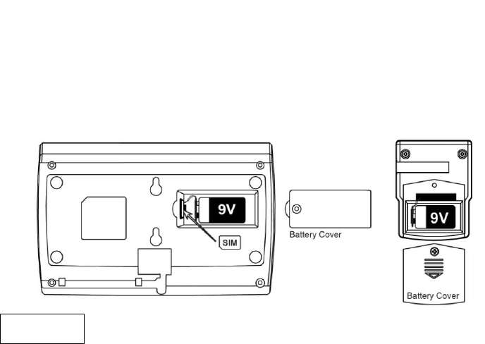
2.2 Battery Installation into Base Unit
Your AX240 base unit provides battery backup support with a 1600mAh rechargeable Li-
Ion battery. Please see figure3 below to install the battery.
Figure 3
24
2.3 Battery Installation into Alert Panel
Your AZ900 alert panel provides battery backup support. Please see figure 4 below to
install the 9V battery.
2.4 Battery Installation into Motion Sensor
To install the battery into the Motion Sensor please see figure4 below.
Figure 4
25
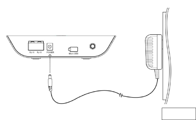
2.5 Connecting the Power Adaptorinto the Base Unit
To connect the power adaptor to the base unit,please see figure 5 below.
Figure 5
26
2.6 Connecting the Power Adaptorinto Alert Panel
To connect the power adaptor to the alert panel,please see figure 6 below.
Figure 6
27
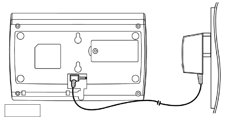
2.7 Setting Up the Base Unit
Connect the antenna by screwing it into the connector on the back of the AX240 base unit.
Connect a wired or cordless telephone to the base unit sing the supplied RJ-11 cord. Plug
the power adaptor cable into the base unit. Plug the power adaptor into an AC power wall
outlet. See figure 7 below.
Figure 7
28
Note: Use only wired or cordless telephones that conform to FCC part 68 requirements.
Non-compliant telephones may not work properly.
WARNING:Do not connect this device to your telephone wall outlet. This configuration is
not supported unless you have taken steps to disconnect existing landline wiring coming
into your home or office.
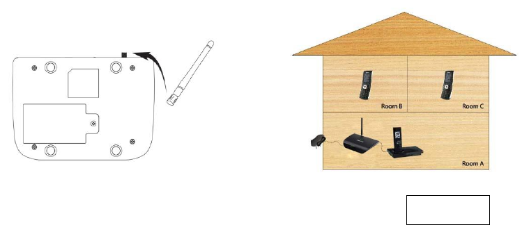
2.8 Placement of the Base Unit
The base unit should be placed on any convenient desktop or table top in the house.
2.9 Placement of Alert Panel
The keypad can be placed at any convenient access point in the house.
2.10 Placement of Motion Sensor
The motion sensor should be placed on shelves or walls and can detect motion within 12
meters, great for rooms with lots of windows.

29
3. Using your 200 Series as a Landline Replacement Phone
3.1 Power On/Off
The power button is located on the top of the AX240. Plug the power adapter into an AC
power wall outlet.Plug the power adapter into the power connector on the back of the
device.
Push the power button on top of the device for several seconds, then release. The green
light will illuminate. Turn the AX240 off by pushing the power button on top of device for
several seconds, then release. The green light will turn off.
3.2 Activation
To activate your AX240 using Over the Air Service Provisioning (if supported by your
carrier) turn on your device.The device will begin its initiation process and start to acquire
the network. Wait 2 minutes to complete. From your connected phone dial *228 and
follow the voice prompts to complete the activation.
NOTE:Check with your service provider before activation as your device may already be
activated.

30
3.3 Setting Up Your Voicemail
You should set up your voicemail and personal greeting as soon as your device is
activated. Always use a password to protect against unauthorized access. Please check
with your service provider for the voicemail access number. Your device automatically
transfers all unanswered calls to your voicemail, even if your device is in use or turned off.
Dial your voicemail number (the phone number assigned to your phone). Follow the
prompts to create your password, record your name announcement, and record your
greeting.
3.4 Making Calls
Check if the device is turned on.Lift the handset on any connected phone. You should
hear a dial tone.Dial a number as you usually would. Wait for about 3 seconds while your
device connects with the number you dialed.
NOTE:You can dial phone numbers with up to 32 digits including and
#

31
3.5 Answering Calls
When connected to your AX240, your phone will ring exactly as if it were connected to a
landline. Lift the handset on any connected phone to answer a call.
3.6 Default Reset
If you want to clear any changes you have made to your AX240’s settings and reset it to
the default settings lift the handset on any connected phone.
Press:
Enter the four-digit lock code (default is “1234”). Press to reset. You will hear two
short tones if successful or four short tones if the reset was unsuccessful.
3.7 Factory Reset
To reset your device to factory conditionlift the handset on any connected phone.
Press:
5
3
#
#
#
4
3
#
#

32
Enter the six-digit SPC default code (the default code is “000000”). You will hear two
short tones if successful and your device will reset or four short tones if the reset was
unsuccessful.
3.8 TTY/TDD Mode Setting
Configure your device for TTY use. The default setting is OFF. Lift the handset on any
connected TTY/TDD phone and choose one of the following options:
Press for TTY Full Mode.
Press for TTY Talk Mode.
Press for TTY Hear Mode.
Press to turn TTY off.
#
3
1
4
#
2
1
4
#
1
1
4
#
0
1
4

33
3.9 Caller ID
Caller ID allows people to identify a caller before answering the phone by displaying the
number of the incoming call. If you do not want your number displayed when you make a
call, follow these steps.
Press . Enter your phone number.
3.10 Setting Caller ID Mode
If the phone you have connected to your AX240 has an LCD display, the caller’s number
will appear by default. To change this setting lift the handset of any connected phone.
Press to disable the Caller ID feature.
Press to re-enable the Caller ID.
3.11 Call Waiting
When you’re on a call, Call Waiting alerts you to incoming calls. When you hear a beep
from the receiver on any connected phone during a call, it means a second caller is trying
#
2
1
2
#
0
1
2
7
6
34
to connect. To use call waiting press the hook or the flash button (if present) to answer
the second call. Press the hook or the flash button again to return to the first call.
3.12 Three-Way Calling
With Three-Way Calling you can talk to two people at the same time. When using this
feature, the normal airtime rates will be charged for each of the two calls. To use Three-
Way Calling call the first party, place a second call by pressing the hook or the flash
button (if present), enter the second party’s number, and press the hook or flash button
again to dial the number. When you are connected to the second party, press the hook or
flash button to start the three-way call.
3.13 E911 Information
Your device features an embedded Global Positioning System (GPS) chip necessary for
utilizing E911 emergency location services where available. During the emergency call,
all the LEDs on the AX240 will blink and your location can then be determined by the 911
operator.
IMPORTANT: Always report your location to the 911 operator when placing an
emergency call. Some designated emergency call takers, known as Public Safety

35
Answering Points (PSAPs) may not be equipped to receive GPS location information from
your device.
4. Using your 200 Series as an Alert System
Now that the battery is installed and the power adaptor is connected you are ready to use
some of the more advanced features of the Axesstel Home Alert. Your 100 Series device
has four operational modes. They are programming mode, armed mode, disarmed mode,
and alarmed mode. The following sections will describe the device’s functionality within
each of these four modes.
4.1 Programming Mode
The programming mode is used for setting the parameters of the Axesstel Home Alert
such as changing the password, adding/deleting SMS/Call numbers, setting entry/exit
delay, and adding/removing motion sensors and other accessories. The programming
mode is also used to restore the device to factory settings. To access the programming
mode please use your keypad and enter the following:
Func KeypasswordFunc Key

36
Please note: All functions listed in this section of the user’s guide require that you
be in the programming mode to perform them. When you are in the programming
mode the Power, Battery, Signal, and Setting/Register LEDs will all be solid green.
When in the programming mode and a sequencehas been initiated a 5 second timer
will be kept. After a key is pressed, if 5 seconds elapse before another key is
pressed all 4 Zone LEDs will blink red 3 times and the programming sequence will
need to begin anew. If 30 seconds elapse before another key is pressed, the
Axesstel Home Alert will exit the programming mode.
When programming is complete to exit the programming mode use your keypad and
enter the following or simply wait for 30 seconds to elapse. All LEDs should return to their
normal state.
Func KeyFunc Key
4.1.1 Changing the Password
To change the default password use your keypad to enter the following:
Func Key00Func Keynew passwordnew passwordFunc Key

37
Please note: It is advisable to change your password as soon as you connect the
Axesstel Home Alert.
*Example: The default password is 1234. If you want to change your password to 4897,
then you would enter the following:
to enter the programming mode, then
to change the password.
Func
7
9
8
4
7
9
8
4
Func
0
0
Func
Func
4
3
2
1
Func

38
4.1.2 Adding SMS Numbers
When a motion sensoror other accessory is triggered in any zone, you can choose to
send an SMS to up to 3 numbers. SMS numbers can be added into your Axesstel Home
Alertin two different manners.
A phone call from the desired number will register that number in the designated slot by
following these instructions. You must be in the programming mode to perform this
function.
Add SMS #1
Func Key31Func Key00Func Key
Then call from phone number
Add SMS #2
Func Key32Func Key00Func Key
Then call from phone number
Add SMS #3
Func Key33Func Key00Func Key
Then call from phone number
As an alternative the SMS numbers can be programmed entirely via the keypad. Once in
the programming mode please enter the following:
Add SMS #1
Func Key31Func KeySMS #1SMS #1Func Key
Add SMS #2
Func Key32Func KeySMS #2SMS #2Func Key
Add SMS #3
Func Key33Func KeySMS #3SMS #3Func Key

39
*Example: If you want to add phone number 123-456-7890 into the first SMS slot, then
you would enter the following:
to enter the programming mode, then
to program the phone number into SMS slot #1
Please note: You have to enter the desired number twice. The number that you entered
will need to match. If the numbers entereddo not match then there will be a long beep
and all 4 Zone LEDs will blink red 3 times. If the numbers match then you will hear 2
beeps and all 4 Zone LEDs will blink green 1 time.
Func
0
9
8
7
6
5
4
3
2
1
0
9
8
7
6
5
4
3
2
1
Func
1
3
Func
Func
4
3
2
1
Func

40
4.1.3 Removing SMS Numbers
To remove the SMS numbers please enter the keypad sequences below. You must be in
the programming mode to perform this function.
Delete All SMS #’s
Func Key40Func Key
Delete SMS #1
Func Key41Func Key
Delete SMS #2
Func Key42Func Key
Delete SMS #3
Func Key43Func Key
4.1.4 Adding Call Numbers
When a motion sensoror other accessory is triggered in any zone, you can choose to
make a phone call to up to 5 numbers. Call numberscan be added into your Axesstel
Home Alertin two different manners.

41
A phone call from the desired number will register that number in the designated slot by
following these instructions. You must be in the programming mode to perform this
function.
Add Call #1
Func Key51Func Key00Func Key
Then call from phone number
Add Call #2
Func Key52Func Key00Func Key
Then call from phone number
Add Call #3
Func Key53Func Key00Func Key
Then call from phone number
Add Call #4
Func Key54Func Key00Func Key
Then call from phone number
Add Call #5
Func Key55Func Key00Func Key
Then call from phone number
As an alternative the call numbers can be programmed entirely via the keypad. Once in
the programming mode please enter the following:
Add Call #1
Func Key51Func KeyCall#1Call#1Func Key
Add Call #2
Func Key52Func KeyCall #2Call #2Func Key
Add Call #3
Func Key53Func KeyCall #3Call #3Func Key
Add Call #4
Func Key54Func KeyCall #4Call #4Func Key
Add Call #5
Func Key55Func KeyCall #5Call #5Func Key

42
*Example: If you want to add phone number 123-456-7890 into the first Call slot, then you
would enter the following:
to enter the programming mode, then
to program the phone number into Call slot #1
Please note: You have to enter the desired number twice. The number that you entered
will need to match. If the numbers entereddo not match then there will be a long beep
and all 4 Zone LEDs will blink red 3 times. If the numbers match then you will hear 2
beeps and all 4 Zone LEDs will blink green 1 time.
Func
0
9
8
7
6
5
4
3
2
1
0
9
8
7
6
5
4
3
2
1
Func
1
5
Func
Func
4
3
2
1
Func

43
4.1.5 Removing Call Numbers
To remove the Call numbers please enter the keypad sequences below. You must be in
the programming mode to perform this function.
Delete All Call #’s
Func Key60Func Key
Delete Call #1
Func Key61Func Key
Delete Call #2
Func Key62Func Key
Delete Call #3
Func Key63Func Key
Delete Call #4
Func Key64Func Key
Delete Call #5
Func Key65Func Key
4.1.6 Adding Sensors
To add motion sensors (AZ100) to the Axesstel Home Alert please follow the instructions
below. Up to 200 Motion sensors and other accessories can be added across 4 zones. In
the rear housing of the motion sensor, there is a small push button switch which is used
for adding the sensor (inclusion) and removing (exclusion) the sensor. The following will
add the AZ100 sensors (inclusion/association) to the 100 Series Axesstel Home Alert
(see figure 4 below).

44
Please note: You will need to remove the motion sensor battery cover in order to register
your sensor. You must be in the programming mode to perform this function.
Add Sensor in Zone 1
Func Key11FuncKey
Zone 1 LED will light then
press the sensor button.
Add Sensor in Zone 2
Func Key12FuncKey
Zone 2 LED will light then
press the sensor button.
Add Sensor in Zone 3
Func Key13FuncKey
Zone 3 LED will light then
press the sensor button.
Add Sensor in Zone 4
Func Key14FuncKey
Zone 4 LED will light then
press the sensor button.
Please note:You need to press the button of the desired sensor within 30 seconds to
registerit correctly. If the sensor has not been registered properly there will be a long
beep and all 4 Zone LEDs will blink red 3 times. If the sensor has been registered
properly then you will hear 2 beeps and all 4 Zone LEDs will blink green 1 time.
To add additional sensors in your desired zone please repeat the above instructions.
45
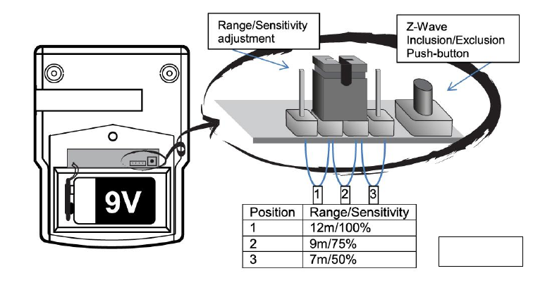
The location of the button in the AZ100 motion sensor is depicting in figure 8. All
approved Z-wave accessories will have an inclusion/exclusion button. Consult the
literature provided with those accessories to properly locate the button.
Figure 8

46
4.1.7 Pet Immunity
The AZ100 passive infrared (PIR) motion detector can be adjusted to provide pet
immunity.
Remove the back cover of the PIR motion sensor (see figure 6) to adjust the
range/sensitivity setting. Moving the jumper to the number 3 position will adjust for
minimum sensitivity. You can also adjust the angle of the sensor slightly upwards to
further minimize pet sensitivity. The sensitivity setting can be adjusted prior to or after the
sensor has been registered.
4.1.8 Removing Sensors
To remove/delete (exclusion) any motion sensors or other accessories please follow the
instructions below. You must be in the programming mode to perform this function.
Remove motion sensor or
other accessory
Func Key10Func Key
Press the sensor button
Please note: You need to press the button of the desired sensor within 30 seconds to
remove (exclude) it correctly. If the procedure has not been accomplished properly

47
therewill be a long beep and all 4 Zone LEDs will blink red 3 times. If the sensor has been
removed properly then you will hear 2 beeps and all 4 Zone LEDs will blink green 1 time.
4.1.9 Adding the Key Fob
To add the 4-Button Key Fob (AZ300) to the Axesstel Home Alert please follow the
instructions below. You must be in the programming mode to perform this function.
Func Key16FuncKey
Press the Arm and Panic Keys simultaneously for at
least 0.5 seconds
You need to press the Key Fob button within 30 seconds to registerit correctly. If the Key
Fob has not been registered properly there will be a long beep and all 4 Zone LEDs will
blink red 3 times. If the Key Fob has been registered properly then you will hear 2 beeps
and all 4 Zone LEDs will blink green 1 time.

48
4.1.10 Adding the Panic Key Fob
To add the 1-Button Panic Key Fob (AZ310) to the Axesstel Home Alert please follow the
instructions below. You must be in the programming mode to perform this function.
Func Key16FuncKey
Press and Release the Panic Key 3 times
You need to press the Panic Key Fob button within 30 seconds to registerit correctly. If
the Panic Key Fob has not been registered properly there will be a long beep and all 4
Zone LEDs will blink red 3 times. If the Panic Key Fob has been registered properly then
you will hear 2 beeps and all 4 Zone LEDs will blink green 1 time.
4.1.11 Set Entry Mode
You can modify the entry time delay to suit your needs. This will delay a sensor from
being triggered from between 0 and 45 seconds. The default entry delay is set to 30
seconds. To adjust the entry delay please follow the instructions below. You must be in
the programming mode to perform this function.
No Entry Delay
Func Key70Func Key
15 Second Delay
Func Key71Func Key
49
30 Second Delay
Func Key72Func Key
45 Second Delay
Func Key73Func Key
Example: If you want to set the entry delay to 15 seconds, then you would enter the
following:
4.1.12 Set Exit Mode
You can modify the exit time delay to suit your needs. This will delay a sensor from being
triggered from between 0 and 120 seconds. The default exit delay is set to 30 seconds.
To adjust the exit delay please follow the instructions below. You must be in the
programming mode to perform this function.
No Exit Delay
Func Key80Func Key
30 Second Delay
Func Key81Func Key
60 Second Delay
Func Key82Func Key
90 Second Delay
Func Key83Func Key
120 Second Delay
Func Key84Func Key
Func
1
7
Func

50
The setting of ‘No Exit Delay’ can only be enabled when the Axesstel Home Alert 100
Series device is armed remotely.
Example: If you want to set the exit delay to 60 seconds, then you would enter the
following:
4.1.13 Factory Reset
If your unit malfunctions or develops any form of software fault then it may be necessary
to perform a factory reset. To do so, please follow the instructions below. After a factory
reset is performed you will need to re-program your SMS/Call numbers and any other
parameters you have changed. You must be in the programming mode to perform this
function.
Func Key90Func Key
Func
2
8
Func

51
4.1.14 Test Mode 1 – Call
Test Mode 1 allows the Axesstel Home Alert to make a phone call to any phone
number.Please follow the instructions below. You must be in the programming mode to
perform this function.
Func Key92Func Keyphone numberFunc Key
4.1.15 Test Mode 2 – SMS
Test Mode 2 allows the Axesstel Home Alert to send an SMS to any phone number.
Please follow the instructions below. You must be in the programming mode to perform
this function.
Func Key93Func Keyphone numberFunc Key

52
4.2 Armed Mode
After the Axesstel Home Alert has been installed, motion sensors have been added, and
the SMS/Call numbers have been programmed it can be used as an alert system. Once
in armed mode any sensor that is triggered in an active zone will initiate the alerting
process. There are 4 different armed modes: Armed Away, Armed Away Silent, Armed
Stay, and Armed Stay Silent.
4.2.1 Armed Away
In the Armed Away mode, when a sensor is triggered, the 100 Series Axesstel Home
Alert will emit a high-pitched continuous siren for 4 minutes. All programmed SMS and
Call numbers will be sent an alert notifying them of the alarm.
To activate the ArmedAwaysimply press the Away/On Key.
Away/On Key
Activates Armed Away Mode
Away
/On
53
4.2.2 Armed Away Silent
The Armed Away Silent mode provides essentially the same functionality as the Armed
Away mode except when a sensor is triggered no high-pitched siren is audible.The
intruder will be unaware that the alarm has been triggered, although SMS/Calls will be
sent.
To activate the Armed AwaySilent simply press the #1 and Away/On Key.
1Away/On Key
Activates Armed Away Silent Mode
4.2.3 Armed Stay
Occasionally you may want to arm only a certain part of your house, and this can be
achieved by using the Armed Stay mode.
Please note:Zones one, two and three will be excluded when using the Armed Stay
mode.You can activate your alarm so that any motion in zonefour will trigger the alarm,
Away
/On
1

54
but if there is any movement in zones one, two or three then the alarm will not be
triggered.
In the Armed Stay mode, when a sensor is triggered, the 100 Series Axesstel Home Alert
will emit a high-pitched continuous siren for 4 minutes. All programmed SMS and Call
numbers will be sent an alert notifying them of the alarm.
To activate the Armed Staysimply press the Stay/On Key.
Stay/On Key
Activates Armed Stay Mode
Stay
/On

55
4.2.4 Armed Stay Silent
The Armed Stay Silent mode provides essentially the same functionality as the Armed
Away mode except when a sensor is triggered no high-pitched siren is audible.The
intruder will be unaware that the alarm has been triggered, although SMS/Calls will be
sent.
Please note:Zones one, two and three will be excluded when using the Armed Stay
Silent mode. You can activate your alarm so that any motion in zonefour will trigger the
alarm, but if there is any movement in zones one, two or three then the alarm will not be
triggered.
To activate the Armed StaySilent simply press the #1 and Stay/On Key.
1Stay/On Key
Activates Armed Stay Silent Mode
Stay
/On
1
56
4.2.5 Remote Arming via Key Fob
You can also arm the Axesstel Home Alert remotely via the Key Fob. Please refer to the
instructions included with your Key Fob.
4.2.6 Remote Arming via Smartphone App
You can also arm the Axesstel Home Alert remotely via the Smartphone (Android/iOS)
App. Please refer to App section in this user’s manual.
4.2.7 Continued Arming
If a sensor has been triggered and after 4 minutes the device has not been disarmed, it
will automatically re-arm. At this point another SMS will be sent to the programmed SMS
numbers (no Calls are made in this instance). This is the case in all 4 armed modes.
4.3 Disarmed Mode
When you return home or wherever you have your Axesstel Home Alert set up you will
want to place it in a disarmed state so no alert notifications are sent. The amount of time
you have to disarm your device is dependent on the entry time delay previously
programmed.There are multiple ways the Axesstel Home Alert can be placed in the
disarmed mode.

57
4.3.1 Disarm via Keypad
To disarm the Axesstel Home Alert using the keypad simply enter your password.
4.3.2 Remote Disarm via Key Fob
You can also arm the Axesstel Home Alert remotely via the Key Fob. Please refer to the
instructions included with your Key Fob.
4.3.3 Remote Disarm via Smartphone App
You can also disarm the Axesstel Home Alert remotely via the Smartphone (Android/iOS)
App. Please refer to App section in this user’s manual.
Password

58
4.4 Alarmed Mode
The alarmed mode isentered when a sensor is triggered and alerts have been sent.
When one of the disarm procedures above is followed the device will be in disarmed
mode, however, the alerts will have already been issued. If no disarm command is
received within 4 minutes the Axesstel Home Alert will re-arm as described in the
continued arming section above. Under this scenario the 100 Series will revert back to
whatever armed status was previously programmed into the device and an additional
SMS will be sent. The alarmed mode can also be initiated by pressing the panic button.
4.4.1 Panic Button
Your Axesstel Home Alert features a panic button, that when pressed, will immediately
activate the siren, as well as alerting your friends and neighbors via SMS and Calls. To
activate the panic button simply press the ‘PANIC’ button which is located on your main
unit.
Panic
Please note: Once the panic button has been activated it can be disabled by the keypad
only, not remotely by SMS application nor key fob.
59
4.5 Additional Functions&Features
This section lists some of the additional functionality and features included in your
Axesstel Home Alert
4.5.1 Audio Monitoring/2-Way Communication
You can dial in to your Axesstel Home Alert and the speaker in the 100 Series allows you
to monitor the surroundings. Using the speaker and microphone also allows you to call in
and have a 2-way conversation with your children or whoever is in the vicinity.
4.5.2 Tamper Prevention
The Axesstel Home Alert possesses tamper prevention functionality. When the base unit
is tampered with (in both Away and Stay modes) an alarm is triggered and alerts are sent.
If no disarmed SMS is received 30 seconds it is an indication that the system may be
smashed.
4.5.3 Audible Siren
The Axesstel Home Alert possesses a siren that will sound when a sensor is triggered.
The siren provides a sound equivalent to that of an omni-directional source with a
pressure level of over 80 decibels.
60
4.5.4 Axesstel Home Alert Accessories
The list of items below are accessories for the 100 Series Axesstel Home Alert available
through Axesstel’s distribution network. Contact your point of purchase for availability.
AZ100 - Motion Sensor
AZ112 - Window/Door Sensor
AZ300.-.4-Button Key Fob
AZ310.- Panic Key Fob

61
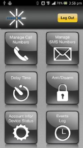
5. AX240 Smartphone Application
The below sections define the Smartphone Application for the Axesstel Home Alert 200
Series. When the device is set up, a phone number must be manually entered into the
main unit in order for it to be recognized from the app. Once in programming mode this
can be done by one of the two methods below:
Func Key31Func KeySMS #1SMS #1Func Key or
Func Key31Func Key00Func Key Then call from phone number
5.1 AX240 App for Android
The AX240 App for android is available from Google Play.
Preconditions
1. Phone is powered on and registered in the network andis
able to launch Google Play
Procedure
1. Open Google Play
2. Search for AX240 App
3. Download the application to the device

62
5.2 AX240 App for iPhone
The AX240 app for iPhone is available from the Apple App Store
Preconditions
1. Phone is powered on
2. Launch App Store
Procedure
1. Open App Store
2. Search for AX240 App
3. Download the application to the device
5.3 AX240 App creating user account (Android/iOS)
Preconditions
1. Phone is powered on
2. The AX240 application has been downloaded and open
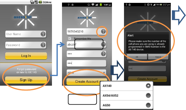
63
Done
Optional
Select Device
64
65
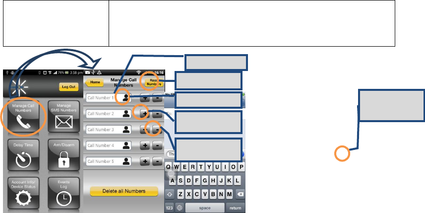
5.4 Manage Call Numbers (Android/iOS)
Preconditions
1. Phone is powered on
2. The AX240 application has been downloaded
3. The SMS number (of the phone using this App) has
already been added in the AX240
Add Call number
Read numbers
from AX140
Add from Phone
Book
Send number to
AX240
Delete number
from AX240
iPhone only; must
press Send.
66
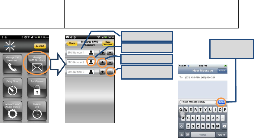
5.5 Manage SMS Numbers(Android/iOS)
Preconditions
1. Phone is powered on
2. The AX240 application has been downloaded
3. The SMS number (of the phone using this App) has
already been added in the AX240
Pre-entered SMS number
Add from Phone Book
Send number to AX240
Delete number from
AX240
iPhone only; must
press Send.
67
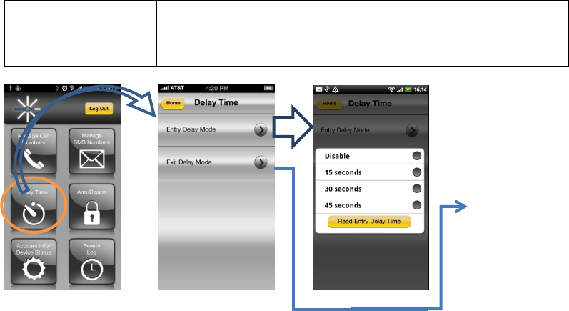
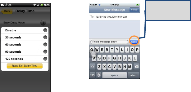
5.6 Delay Time (Entry/Exit )
Preconditions
1. Phone is powered on
2. The AX240 application has been downloaded
3. The SMS number (of the phone using this App) has
already been added in the AX240
68
iPhone only; must
press Send.
69
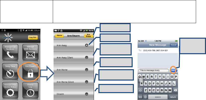
5.7 Remote Arming/Disarming
Preconditions
1. Phone is powered on
2. The AX240 application has been downloaded
3. The SMS number (of the phone using this App) has
already been added in the AX240
Read Status
Normal Arming
Normal Arming;
No Siren
Arm when at Home
Arm when at Home, no
Siren.
Disarm Alarm
iPhone only;
must press
Send.
70
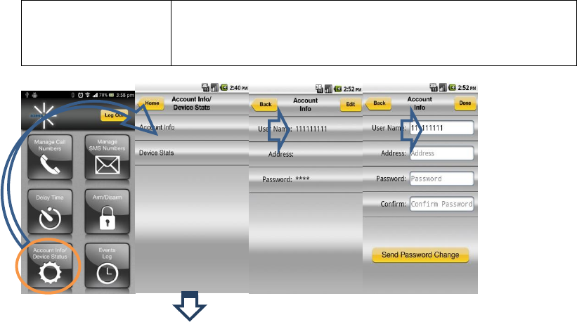
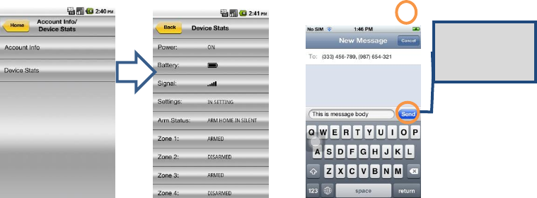
5.8 Account Info/Device Status (Android/iOS)
Preconditions
1. Phone is powered on
2. The AX240 application has been downloaded
3. The SMS number (of the phone using this App) has
already been added in the AX240
71
Android
iPhone only; must
press Send.
Status Displayed in
SMS Message box.
72
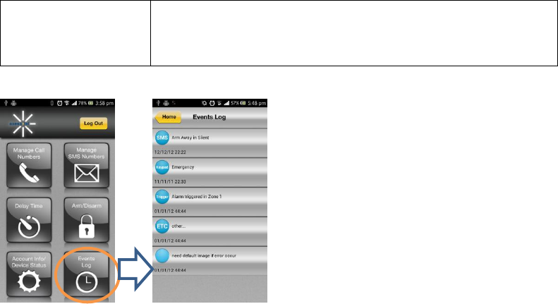
5.9 Event Log
Preconditions
1. Phone is powered on
2. The AX240 application has been downloaded
3. The SMS number (of the phone using this App) has
already been added in the AX240

73
Z-Wave
Interoperability with Z-Wave Devices:
Every Z-Wave certified device is designed to work with allother Z-Wave certified devices.
The Z-Wave network canintegrate devices of various classes, and these devices canbe
made by different manufacturers. The AX140 is a dedicated controller; since it uses the
Basic Command Class, it can provide limited control of other Z-Wave devices using this
command class.
Wireless range:
This device has an open air line of sight transmission distance of 100 feet which complies
with the Z-Wave standards. Performance can varydepending on the amount of objects
between Z-Wave devices suchas walls and furniture. Every installed Z-Wave device
willact as a signal repeater allowing devices to talk to each other and will findalternate
routes/paths, in the case of a reception dead spot.
Radio frequency limitations:
1. Each wall or object (i.e.: refrigerator, bookshelf, large TV, etc) canreduce the maximum
range of 65 feet by up to 25 to 30%.
74
2. Plasterboard and wooden walls block less of the radio signal thenconcrete, brick or tile
walls which will have more of an effect onsignal strength.
3. Wall mounted Z-Wave devices will also suffer a loss of range asthey are housed in
metal junction boxes which could reduce therange by up to 25 to 30%.
Z-Wave basic terminology:
Include /Exclude: Includeand exclude are the Z-Wave terms used to describe
adding,removing or deleting devices to or from the control network.
Replicate: This is the Z-Waveterm for copying or transferringthe Z-Wave network data (all
devices) to anew controller. This process isalso used to update secondarycontrollers after
changes havebeen made to the controlnetwork with the primarycontroller.
Functional Overview:
This device is based on the Z-Wave Controller Library and works with devices that
support the following Z-Wave Device/Command Classes:
Z-Wave device type:
Basic Device Class: BASIC_TYPE_CONTROLLER
Generic Device Class: GENERIC_TYPE_STATIC_CONTROLLER

75
Specific Device Class: SPECIFIC_TYPE_NOT_USED
Z-Wave Command Class
Controlled
Supported
COMMAND_CLASS_BASIC
NO
YES
COMMAND_CLASS_SENSOR_BINARY
YES
NO
COMMAND_CLASS_VERSION
YES
YES
COMMAND_CLASS_MANUFACTURER_SPECIFIC
YES
YES
COMMAND_CLASS_WAKE_UP
YES
NO
COMMAND_CLASS_ALARM
YES
NO
COMMAND_CLASS_CONTROLLER_REPLICATION
NO
YES
76
Compatible Devices:
Z-Wave devices may vary; follow the instructions in the User’s Guide for your specific
device when adding and deleting devicesinto the Z-Wave network. Not all features are
supported for off-the-shelf Z-Wave devices.
Basic Z-Wave Functions:
Adding 3rd party vendor Z-Wave device; please refer to the instructions for the Z-Wave
device that you are installing.
Inclusion: Add a Z-Wave enabled device
On AX140 enter the command [#password75 Func-Key]; on other Z-
Wave device [Press switch to enter inclusion mode (see manufactures
instructions for device)]
Exclusion: Remove a Z-Wave enabled device.
On AX140 enter the command [#password70Func-Key]; on other Z-
Wave device [Press switch to enter inclusion mode (see manufactures
instructions for device)]
77
Association: After inclusion, define the relationship between devices
(primary/secondary), by specifying one as primary to control the other secondary
device.
On AX140 enter the command [#password81Group IDFunc-Key]; on
the other Z-Wave sensor [Click the button in secondary sensor first then in the
primarysensor; this will add the primary sensor to secondary sensor association
group(see manufactures instructions for device)] If no Group ID is found, user can
specify (example “1”).
To Remove the Association (primary sensor from secondary sensor):
On AX140 enter the command [#password82Group IDFunc-Key].
Manual Association to the AX140 Controller:
On AX140 enter the command [#password83Group IDFunc-Key]; Click
the Z-Wave button on the primary sensor will add it to Controller Association
Group.
To Remove the primary sensor Association Group:
On AX140 enter the command [#password84Group IDFunc-Key]
78
Learn Mode: How to make the AX140 become a secondary controller. On AX140
enter the command [#password85Func-Key]. Click Z-Wave button on the
primary controller.
Controller Shift: How to go back/shift back to primary controller. On AX140 enter
the command [#password86Func-Key]. Click Z-Wave button on the
secondary controller.

79
Operating Specifications
1. Base Unit AX240
Item
Description
Air Interface
CDMA2000 1X-Advanced
RF Frequency
800MHz/1900MHz Dual Band
LED
5
Interface
2 RJ-11 Ports (bridged), Max 4 REN
DC Power Jack
Power On/Off Button
TNC Connector for CDMA antenna
Special Features
AGPS for E911 Service
Automatic Sending Caller ID
DTMF, Bellcore
Tone
Dial, No Service, Howler, Stutter, Menu OK, Menu NOK
Call Features
Hook Flash, Call Waiting, Call Forwarding, Three-Way
Calling
Battery
1600mAh Li-Ion rechargeable
Power adapter
5V/2A

80
Size
6.8*5.0*1.3 inches (174*128*34 mm)
Weight
9 ounces (255g) (without battery)
Operating Temperature
-13~140oF (-25~+60oC)
Operating Humidity
0% to 95%
2. Alert Panel AZ900
Item
Description
CDMA 2000/1XRTT
800/1900 MHz
Size
7.8*4.9*1.5 inches (198*126*38 mm)
Weight
12 ounces (340g)
Antenna
CDMA Dual Band antenna
Z-Wave 908.42MHz
Up to 100 feet line of sight
LED
10
Key
16
SMS numbers
3 phone numbers
CALL numbers
5 phone numbers
Zones
4 zones
Power adapter
5V/2A

81
3. Motion Sensor AZ100
Item
Description
Detection mode
Passive infrared signal (PIR)
Size
3.3*2.5*1.8 inches (85*65*45 mm)
Weight
2.8 ounces (80g)
Antenna
Build in Z-Wave antenna
Transmit distance
Up to 100 feet line of sight
Detection range
23-39.4 ft. (7-12 m)
LED
Red & Green
Motion sensitivity adjust
3 levels
Tamper switch
Support
Battery
9V
Z-Wave Band Frequency
908.42MHz
RSSI
-102dBm
Operating Temperature
14~122oF (-10~+50oC)
Storage Temperature
-4~158oF (-20~+70oC)
Humidity
0% to 95%

82
Battery
9V
Z-Wave Band Frequency
908.42MHz
RSSI
-102dBm
Working Temperature
32~122oF (0~+50oC)
Storage Temperature
14~176oF (-10~+80oC)
Humidity
0% to 95%
Safety Information
This device complies with Part 15 of the FCC Rules. Its operation is subject to the
following two conditions:
(1) This device may not cause harmful interference, and
(2) this device must accept any interference received, including interference that may
cause undesired operation.
Note: This product has been tested and found to comply with the limits for a Class B
digital device, pursuant to Part 15 of the FCC Rules. These limits are designed to provide
reasonable protection against harmful interference in a residential installation. This

83
product generates, uses, and can radiate radio frequency energy and, if not installed and
used in accordance with the instructions, may cause harmful interference to radio
communications. However, there is no guarantee that interference will not occur in a
particular installation. If this product does cause harmful interference to radio or television
reception, which can be determined by turning the equipment offand on, the user is
encouraged to try to correct the interference by one or more of the following measures:
—Reorient or relocate the receiving antenna.
—Increase the separation between the equipment and receiver.
—Connect the equipment into an outlet on a circuit different from that to which the receiver
is connected.
—Consult the dealer or an experienced radio/TV technician for help.
FCC Caution: Any changes or modifications not expressly approved by the party
responsible for compliance could void the user's authority to operate this equipment.
This transmitter must not be co-located or operating in conjunction with any other antenna
or transmitter.

84
Radiation Exposure Statement:
This device meets the government’s requirements for exposure to radio waves.
This device is designed and manufactured not to exceed the emission limits for exposure
to radio frequency (RF) energy set by the Federal Communications Commission of the
U.S. Government.
The exposure standard for wireless device employs a unit of measurement known as the
Specific Absorption Rate, or SAR. The SAR limit set by the FCC is 1.6W/kg. *Tests for
SAR are conducted using standard operating positions accepted by the FCC with the
device transmitting at its highest certified power level in all tested frequency bands.
AX240 Series v0.4 20130816 AXESSTEL INC.
6815 Flanders Drive Ste. 210
San Diego, CA 92121, USA
www.axesstel.com
85
© Axesstel Inc, All Rights Reserved