AzureWave Technologies UR500 Range Maximizer-515 User Manual Range Mzximizer 515 QG EN indd

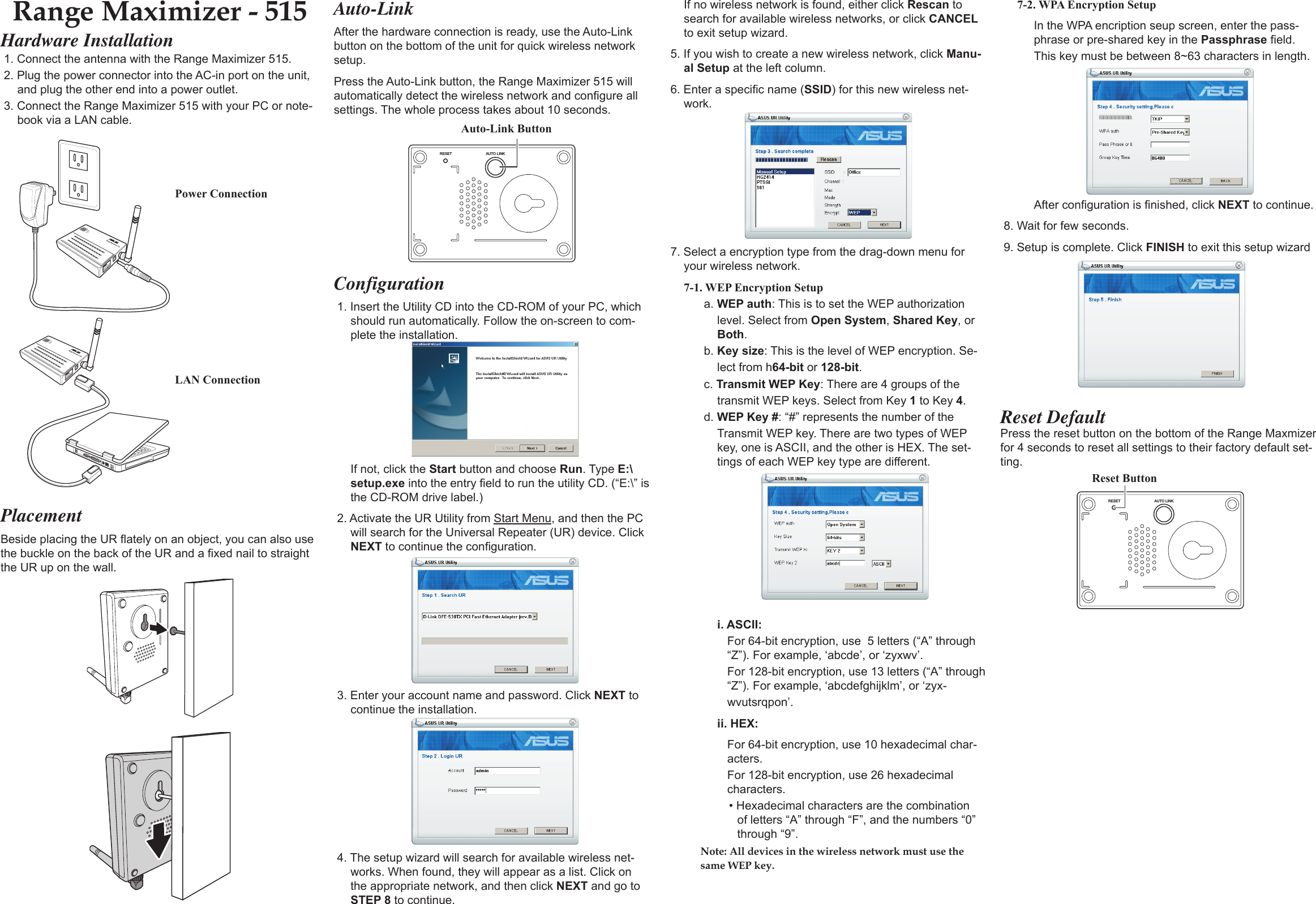
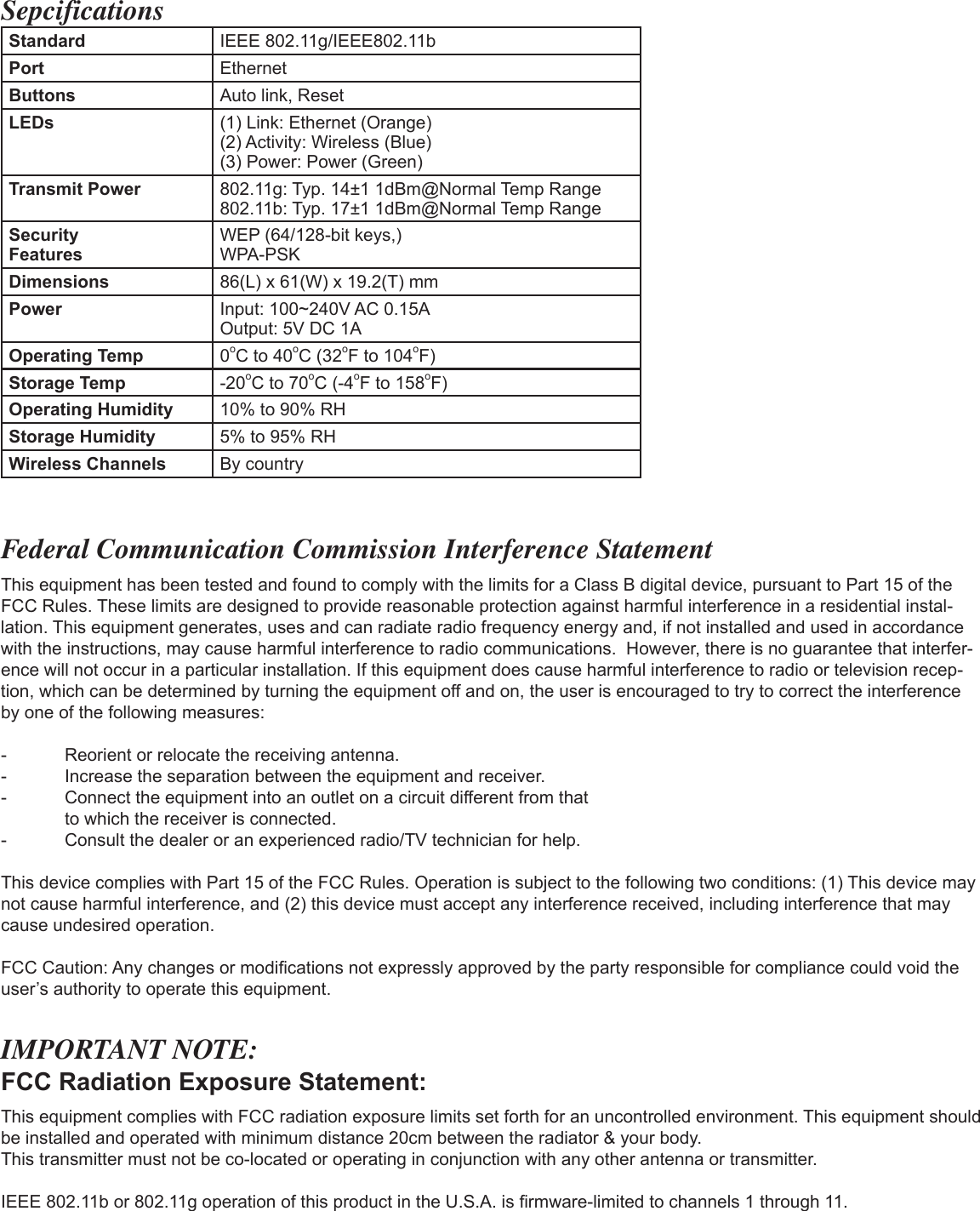
AzureWave Technologies, Inc. Range Maximizer-515 Range Mzximizer 515 QG EN indd

Manual

Hardware Installation1. Connect the antenna with the Range Maximizer 515.2. Plug the power connector into the AC-in port on the unit, and plug the other end into a power outlet.3. Connect the Range Maximizer 515 with your PC or note-book via a LAN cable.Configuration1. Insert the Utility CD into the CD-ROM of your PC, which should run automatically. Follow the on-screen to com-plete the installation. If not, click the Start button and choose Run. Type E:\setup.exe into the entry field to run the utility CD. (“E:\” is the CD-ROM drive label.)2. Activate the UR Utility from Start Menu, and then the PC will search for the Universal Repeater (UR) device. Click NEXT to continue the configuration.3. Enter your account name and password. Click NEXT to continue the installation.4. The setup wizard will search for available wireless net-works. When found, they will appear as a list. Click on the appropriate network, and then click NEXT and go to STEP 8 to continue.Auto-LinkAfter the hardware connection is ready, use the Auto-Link button on the bottom of the unit for quick wireless network setup.Press the Auto-Link button, the Range Maximizer 515 will automatically detect the wireless network and configure all settings. The whole process takes about 10 seconds.AUTO LINKRESETAuto-Link ButtonPower ConnectionLAN ConnectionReset DefaultPress the reset button on the bottom of the Range Maxmizer for 4 seconds to reset all settings to their factory default set-ting.AUTO LINKRESETReset ButtonIf no wireless network is found, either click Rescan to search for available wireless networks, or click CANCEL to exit setup wizard.5. If you wish to create a new wireless network, click Manu-al Setup at the left column.6. Enter a specific name (SSID) for this new wireless net-work.7. Select a encryption type from the drag-down menu for your wireless network.7-1. WEP Encryption Setupa. WEP auth: This is to set the WEP authorization level. Select from Open System, Shared Key, or Both.b. Key size: This is the level of WEP encryption. Se-lect from h64-bit or 128-bit. c. Transmit WEP Key: There are 4 groups of the transmit WEP keys. Select from Key 1 to Key 4.d. WEP Key #: “#” represents the number of the Transmit WEP key. There are two types of WEP key, one is ASCII, and the other is HEX. The set-tings of each WEP key type are different.i. ASCII:For 64-bit encryption, use  5 letters (“A” through “Z”). For example, ‘abcde’, or ‘zyxwv’.For 128-bit encryption, use 13 letters (“A” through “Z”). For example, ‘abcdefghijklm’, or ‘zyx-wvutsrqpon’.ii. HEX:For 64-bit encryption, use 10 hexadecimal char-acters. For 128-bit encryption, use 26 hexadecimal characters.• Hexadecimal characters are the combination of letters “A” through “F”, and the numbers “0” through “9”.Note: All devices in the wireless network must use the same WEP key.PlacementBeside placing the UR flately on an object, you can also use the buckle on the back of the UR and a fixed nail to straight the UR up on the wall.7-2. WPA Encryption SetupIn the WPA encription seup screen, enter the pass-phrase or pre-shared key in the Passphrase field. This key must be between 8~63 characters in length.After configuration is finished, click NEXT to continue.8. Wait for few seconds.9. Setup is complete. Click FINISH to exit this setup wizardRange Maximizer - 515
SepcificationsStandard IEEE 802.11g/IEEE802.11bPort EthernetButtons Auto link, ResetLEDs (1) Link: Ethernet (Orange)(2) Activity: Wireless (Blue)(3) Power: Power (Green)Transmit Power 802.11g: Typ. 14±1 1dBm@Normal Temp Range802.11b: Typ. 17±1 1dBm@Normal Temp RangeSecurity FeaturesWEP (64/128-bit keys,)WPA-PSKDimensions 86(L) x 61(W) x 19.2(T) mmPower Input: 100~240V AC 0.15AOutput: 5V DC 1AOperating Temp 0oC to 40oC (32oF to 104oF)Storage Temp -20oC to 70oC (-4oF to 158oF)Operating Humidity 10% to 90% RHStorage Humidity 5% to 95% RHWireless Channels By countryFederal Communication Commission Interference StatementThis equipment has been tested and found to comply with the limits for a Class B digital device, pursuant to Part 15 of the FCC Rules. These limits are designed to provide reasonable protection against harmful interference in a residential instal-lation. This equipment generates, uses and can radiate radio frequency energy and, if not installed and used in accordance with the instructions, may cause harmful interference to radio communications.  However, there is no guarantee that interfer-ence will not occur in a particular installation. If this equipment does cause harmful interference to radio or television recep-tion, which can be determined by turning the equipment off and on, the user is encouraged to try to correct the interference by one of the following measures:-  Reorient or relocate the receiving antenna.-  Increase the separation between the equipment and receiver.-  Connect the equipment into an outlet on a circuit different from that  to which the receiver is connected.-  Consult the dealer or an experienced radio/TV technician for help.This device complies with Part 15 of the FCC Rules. Operation is subject to the following two conditions: (1) This device may not cause harmful interference, and (2) this device must accept any interference received, including interference that may cause undesired operation.FCC Caution: Any changes or modifications not expressly approved by the party responsible for compliance could void the user’s authority to operate this equipment.IMPORTANT NOTE:FCC Radiation Exposure Statement:This equipment complies with FCC radiation exposure limits set forth for an uncontrolled environment. This equipment should be installed and operated with minimum distance 20cm between the radiator & your body.This transmitter must not be co-located or operating in conjunction with any other antenna or transmitter.IEEE 802.11b or 802.11g operation of this product in the U.S.A. is firmware-limited to channels 1 through 11.

Navigation menu