B plus B SmartWorx WLNG1 802.11 b/g module User Manual
B&B; Electronics 802.11 b/g module Users Manual
UserManual.wiki
>
B plus B SmartWorx
>
WLNG1 User Manual
>
Users Manual
Contents
1.
Users Manual
2.
User Manual
Users Manual
Navigation menu
Upload a User Manual
Namespaces
Wiki Guide
HTML
PDF
Info
Views
User Manual
Discussion / Help
Navigation


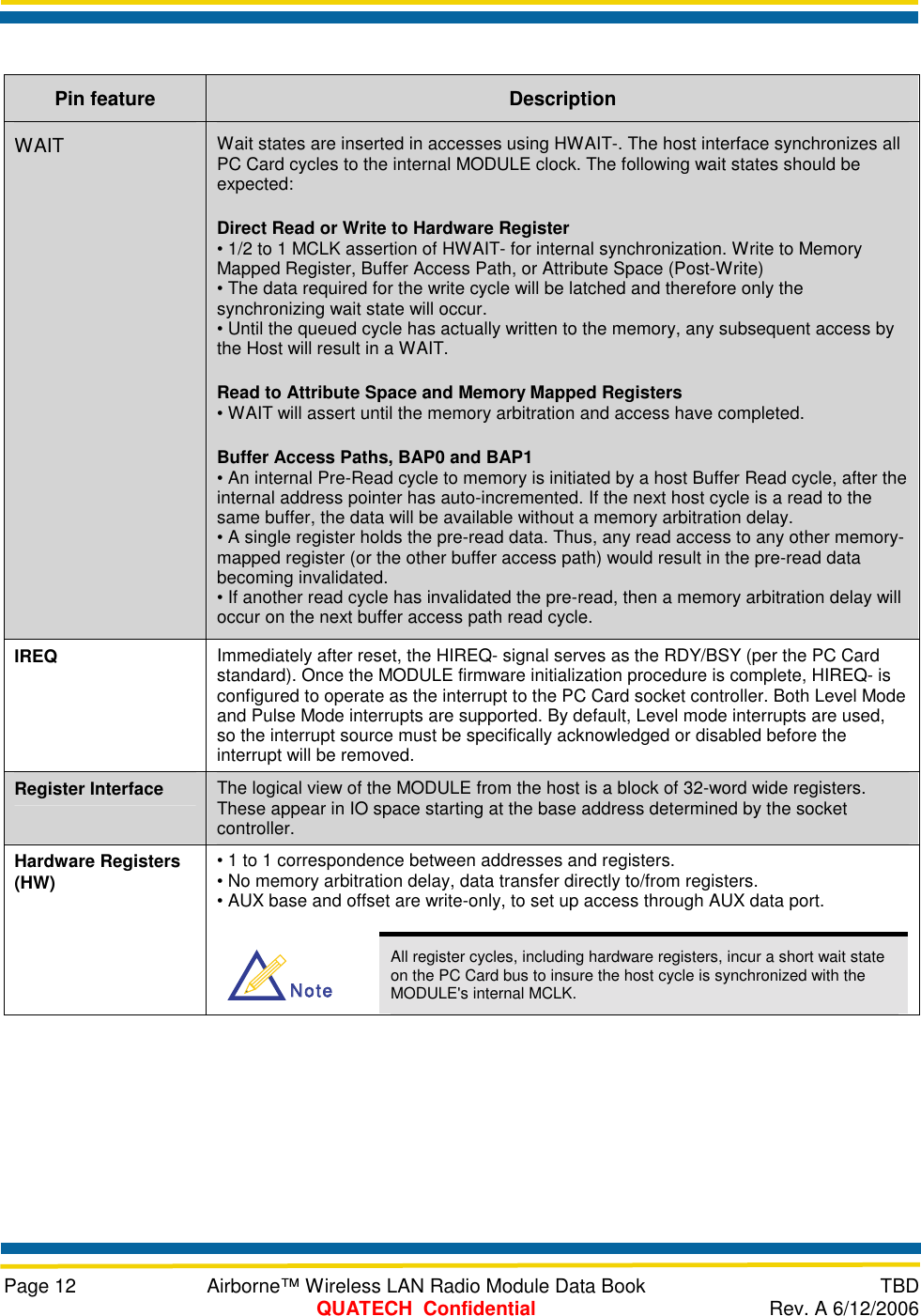
![Page 11 Airborne™ Wireless LAN Radio Module Data Book TBD QUATECH Confidential Rev. A 6/12/2006 Table 9 - Pin Definition and Descriptions Pin feature Description A[9:0] Decoding of the system address space is performed by the CEx-. During I/O accesses A[5:0] decode the register. A[9:6] are ignored when the internal HAMASK register is set to the defaults used by the standard firmware. During attribute memory accesses A[9:1] are used. D[15:0] The host interface is primarily designed for word accesses, although all byte access modes are fully supported. See CE1-, CE2- for a further description. Note that attribute memory is specified for and operates with even bytes accesses only. CE1-, CE2- The PC Card cycle type and width are controlled with the CE signals. Word and Byte wide accesses are supported, using the combinations of HCE1-, HCE2-, and HA0 as specified in the PC Card standard. WE-, OE HOE and HWE- are only used to access attribute memory. Common Memory, as specified in the PC Card standard, is not used in the MODULE. HOE- is the strobe that enables an attribute memory read cycle. HWE- is the corresponding strobe for the attribute memory write cycle. The attribute space contains the Card Information Structure (CIS) as well as the Function Configuration Registers (FCR). IORD-, IOWR IORD-and HIOWR- are the enabling strobes for register access cycles to the MODULE. These cycles can only be performed once the initialization procedure is complete and the MODULE has been put into IO mode. REG This signal must be asserted for I/O or attribute cycles. A cycle where HREG- is not asserted will be ignored as the MODULE does not support common memory. INPACK This signal is asserted by the MODULE whenever a valid I/O read cycle takes place. A valid cycle is when HCE1-, HCE2-,- HREG-, and HIORD- are asserted, once the initialization procedure is complete.](https://usermanual.wiki/B-plus-B-SmartWorx/WLNG1.Users-Manual/User-Guide-681988-Page-20.png)
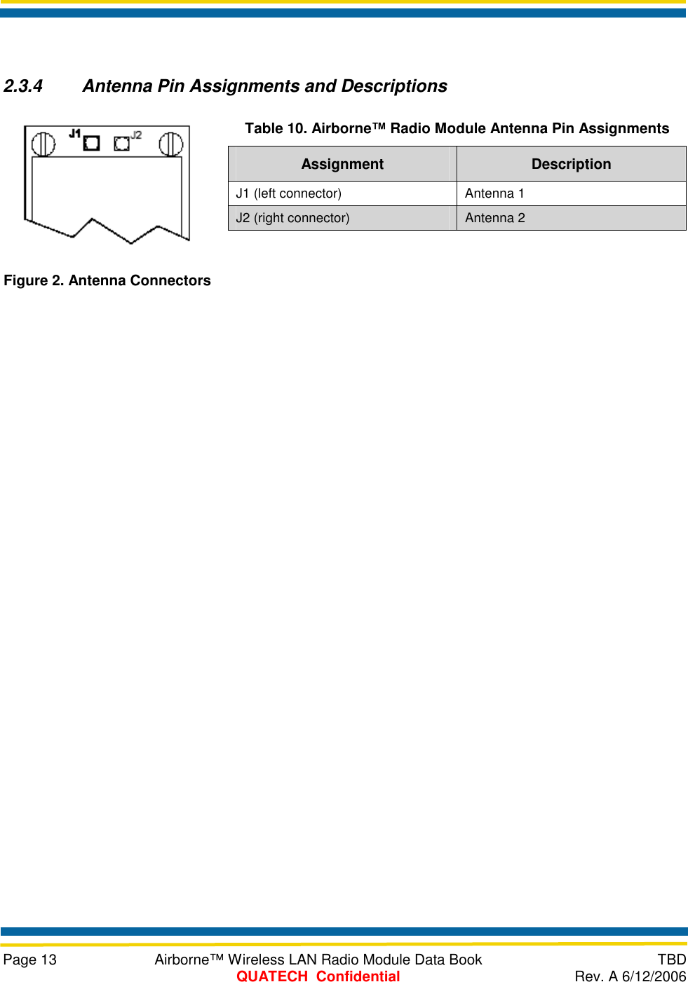


![Page 16 Airborne™ Wireless LAN Radio Module Data Book TBD QUATECH Confidential Rev. A 6/12/2006 inch [mm]1.17 [29.7]0.83 [21.1]1.60 [40.6]0.17 [4.3]1.26 [32.0]0.01[0.2]0.17 [4.3]0.41[10.5]3XØ0.09 [Ø2.2]THIS AREA CLEARFROM INTERCONNECTAND COMPONENTS250149 Figure 4. Guidelines for Mounting the Radio Module 3.4 MOUNTING GUIDELINES Special care must be observed when placing the Module. In particular: The antenna must not be mounted beneath any other printed circuit boards, components, or metallic housing. The proximity of the antenna to large metallic objects can affect the range and performance of the Module. Packaging and enclosure designers must carefully review the placement of the Module in the enclosure to minimize interference or blocking sources. For mechanical clearance, performance, and emissions reasons, there should be no components placed on the main printed circuit board facing the Module. This region should be clear of components. NoteNote Suggested mounting: Use three non conductive spacers with the following dimensions: O/D Diameter 0.187 x I/D Diameter 0.096 x Length 0.156](https://usermanual.wiki/B-plus-B-SmartWorx/WLNG1.Users-Manual/User-Guide-681988-Page-25.png)