B plus B SmartWorx WLNG1 802.11 b/g module User Manual
B&B; Electronics 802.11 b/g module Users Manual
Contents
- 1. Users Manual
- 2. User Manual
Users Manual
AirborneTM 802.11b/g Radio Module Data
Book
Quatech, Inc. Confidential

Page ii Airborne™ Wireless LAN Radio Module Data Book TBD
QUATECH Confidential Rev. A 6/12/2006
Copyright © 2004 QUATECH ® Inc.
ALL RIGHTS RESERVED. No part of this publication may be copied in any form, by photocopy,
microfilm, retrieval system, or by any other means now known or hereafter invented without the
prior written permission of QUATECH ® Inc.. This document may not be used as the basis for
manufacture or sale of any items without the prior written consent of QUATECH Inc..
QUATECH Inc. is a registered trademark of QUATECH Inc..
Airborne™ is a trademark of QUATECH Inc..
All other trademarks used in this document are the property of their respective owners.
Disclaimer
The information in the document is believed to be correct at the time of print. The reader
remains responsible for the system design and for ensuring that the overall system satisfies its
design objectives taking due account of the information presented herein, the specifications of
other associated equipment, and the test environment.
QUATECH ® Inc. has made commercially reasonable efforts to ensure that the information
contained in this document is accurate and reliable. However, the information is subject to
change without notice. No responsibility is assumed by QUATECH for the use of the
information, nor for infringements of patents or other rights of third parties. This document is the
property of QUATECH ® Inc.. and does not imply license under patents, copyrights, or trade
secrets.
Quatech, Inc. Headquarters
QUATECH ® Inc..
5675 Hudson Industrial Parkway
Hudson, OH 44236
USA
Telephone: 330-655-9000
Toll Free: 800-553-1170
Fax: 330-655-9010
Technical Support: 714-899-7543 / wirelesssupport@Dpactech.com
Web Site: www.quatech.com

Page iii Airborne™ Wireless LAN Radio Module Data Book TBD
QUATECH Confidential Rev. A 6/12/2006
CONTENTS
CHAPTER 1 INTRODUCTION.............................................................................................................1
1.1 OVERVIEW ....................................................................................................................................1
1.2 CONFIGURATIONS ..........................................................................................................................1
1.3 FEATURES.....................................................................................................................................1
1.3.1 General Features.................................................................................................................1
1.3.2 Radio Features ....................................................................................................................2
1.3.3 Medium Access Controller and Baseband Processor Features..........................................2
1.4 MODULE BLOCK DIAGRAM...............................................................................................................3
1.5 USING THIS DOCUMENT .................................................................................................................3
1.6 CONVENTIONS ...............................................................................................................................4
1.6.1 Terminology.........................................................................................................................4
1.6.2 Notes ...................................................................................................................................4
1.6.3 Cautions...............................................................................................................................4
1.7 RELATED DOCUMENTATION............................................................................................................4
1.8 FCC STATEMENT ..........................................................................................................................5
1.9 FCC RF EXPOSURE STATEMENT ...................................................................................................5
1.10 INFORMATION FOR CANADIAN USERS (IC NOTICE)..........................................................................5
CHAPTER 2 SPECIFICATIONS...........................................................................................................2
2.1 ELECTRICAL SPECIFICATIONS.........................................................................................................2
2.1.1 Absolute Maximum Ratings.................................................................................................5
2.1.2 Electrical Characteristics .....................................................................................................6
2.2 RADIO FREQUENCY SPECIFICATIONS..............................................................................................7
2.2.1 AC Electrical Characteristics – Transmitter .........................................................................7
2.2.2 Performance/Range.............................................................................................................7
2.3 INTERFACE SPECIFICATIONS...........................................................................................................8
2.3.1 Interface Specifications........................................................................................................8
2.3.2 Pin Assignments ..................................................................................................................8
2.3.3 Pin Features*.....................................................................................................................10
2.3.4 Antenna Pin Assignments and Descriptions......................................................................13
2.4 MECHANICAL SPECIFICATIONS......................................................................................................14
CHAPTER 3 APPLICATION...............................................................................................................15
3.1 DESIGN GUIDELINES ....................................................................................................................15
3.2 EMI/RFI GUIDELINES ..................................................................................................................15
3.3 CIRCUIT BOARD LAYOUT PRACTICES ............................................................................................15
3.4 MOUNTING GUIDELINES ...............................................................................................................16
APPENDIX A: RADIO FREQUENCY CHANNELS..................................................................................18
A.1. USING RADIO FREQUENCIES ........................................................................................................18
A.2. AUTHORIZED FREQUENCY CHANNELS BY REGION .........................................................................19
APPENDIX B: GLOSSARY......................................................................................................................20

Page iv Airborne™ Wireless LAN Radio Module Data Book TBD
QUATECH Confidential Rev. A 6/12/2006
LIST OF FIGURES
Figure 1. Airborne™ Radio Module Block Diagram.....................................................................................3
Figure 2. Antenna Connectors...................................................................................................................13
Figure 3. Mechanical Dimensions .............................................................................................................14
Figure 4. Guidelines for Mounting the Radio Module ................................................................................16
LIST OF TABLES
Table 1. Airborne™ Radio Module Configuration........................................................................................1
Table 2. Electrical Supply Specifications for Airborne™ Radio Module ......................................................2
Table 3. Electrical Specifications for Airborne™ Radio Module ..................................................................2
Table 4. Absolute Maximum Ratings and Operating Environment..............................................................5
Table 5. Electrical Characteristics ..............................................................................................................6
Table 6. Radio Frequency Specifications ....................................................................................................7
Table 7. Performance/Range*.....................................................................................................................8
Table 8. Pin Assignments............................................................................................................................8
Table 9 - Pin Definition and Descriptions ..................................................................................................11
Table 10. Airborne™ Radio Module Antenna Pin Assignments ................................................................13
Table 11. Radio Frequency Channels .......................................................................................................18
Table 12. IEEE 802.11 Channels ..............................................................................................................19

Page v Airborne™ Wireless LAN Radio Module Data Book TBD
QUATECH Confidential Rev. A 6/12/2006
This page intentionally left blank

Page 1 Airborne™ Wireless LAN Radio Module Data Book TBD
QUATECH Confidential Rev. A 6/12/2006
1.1 OVERVIEW
Airborne™ is a line of highly integrated 802.11b/g modules. The Airborne™ Radio Module delivers a
highly integrated solution for consumer and industrial wireless applications using the industry-standard
IEEE 802.11b/g platform. It delivers both a cost and space efficient solution using a small profile design
and direct down SMT high density header (Zero-IF) connection to the system board.
The two-chip design significantly reduces product cost and form factor. It is a complete high-speed
wireless solution that uses the latest 802.11b/g chipset from Marvell which is backward compatible with
the 802.11b DSSS standard and adds the new 802.11g OFDM (orthogonal Frequency Division
Multiplexing) standard support. This chip set includes integrated antenna connectors that provide a direct
connection from the radio to the antenna. This bypasses the system board, which simplifies the
integrator’s board design. The radio is a true upgrade option because no soldered connections are
required. It can be upgraded in the field or added to a managed product configuration.
1.2 CONFIGURATIONS
The Airborne™ Radio Module consists of an 802.11b/g radio transceiver and Media Access Controller
(MAC) with a Compact Flash (CF) interface.
Table 1. Airborne™ Radio Module Configuration
Configuration Description QUATECH Part
Number
Airborne™ Radio Module Supports 802.11b/g radio transceiver and MAC with CF
(Compact Flash) Card interface. WLRG-RA-DP101
1.3 FEATURES
1.3.1 General Features
Highly integrated IEEE 802.11b/g wireless module with radio and baseband processor
IEEE 802.11b/g support up to 54Mbps OFDM(G-Mode) as well as up to 11Mbps DSSS (B-
Mode) legacy rates
Seamless roaming within the IEEE 802.11b/g WLAN infrastructure
CHAPTER 1
INTRODUCTION

Page 2 Airborne™ Wireless LAN Radio Module Data Book TBD
QUATECH Confidential Rev. A 6/12/2006
IEEE 802.11b/g-compatible, allowing interoperation among vendors who also adhere to the
IEEE 802.11 specification
Auto fallback: 11 Mbps, 5.5 Mbps, 2 Mbps, and 1 Mbps data rates for 802.11b mode and
54Mbps, 48Mbps, 36Mbps, 24Mbps, 18Mbps, 12Mbps, 9Mbps, and 6Mbps
64-bit or 128-bit WEP encryption, set by ASCII and Hexadecimal modes
Small size: 38 x 27 x 4.2 mm
Supports site survey functions
Power Saving Mode to prolong battery life
Complies with Wi-Fi standards
1.3.2 Radio Features
IEEE 802.11b/g 54 Mbps/2.4 GHz optimized for consumer and industrial applications
Marvell chipset designed for increased battery life
Performance optimized for web pads, mobile MP3, and other Internet appliances
Wi-Fi Protected Access™ support
On-chip A/D and D/A converters for I/Q data, AGC, and adaptive power control
Designed to meet FCC Part 15 regulatory requirements for operation in 2.4GHz ISM band
Support for 802.11b mode 11, 5.5, 2 and 1 Megabit Per Second (Mbps) Data Rates as well as
802.11g mode 54Mbps, 48Mbps, 36Mbps, 24Mbps, 18Mbps, 12Mbps, 9Mbps, and 6Mbps
Data Rates
Supports the lEEE 802.11b Direct Sequence Specification as well as 802.11g OFDM
Specification
Supports Dual Diversity Antennas
Intelligent Power Control, Including Low Power Standby Mode
1.3.3 Medium Access Controller and Baseband Processor Features
Enhanced performance WEP engine
Debug mode supports tracing execution from on-chip memory
Complete DSSS baseband processor for B-Mode and OFDM baseband processor for G-
Mode
Processing gain is FCC compliant (B-Mode)
Programmable data rate is 1, 2, 5.5, and 11Mbps for B-Mode and 54Mbps, 48Mbps, 36Mbps,
24Mbps, 18Mbps, 12Mbps, 9Mbps, and 6Mbps for G-Mode
Modulation methods: DBPSK, DQPSK, and CCK for B-Mode and BPSK, QPSK, 16-QAM, and
64-QAM for G-Mode
Page 3 Airborne™ Wireless LAN Radio Module Data Book TBD
QUATECH Confidential Rev. A 6/12/2006
Supports half duplex operation
Supports short preamble (B-Mode) and antenna diversity (Rx only)
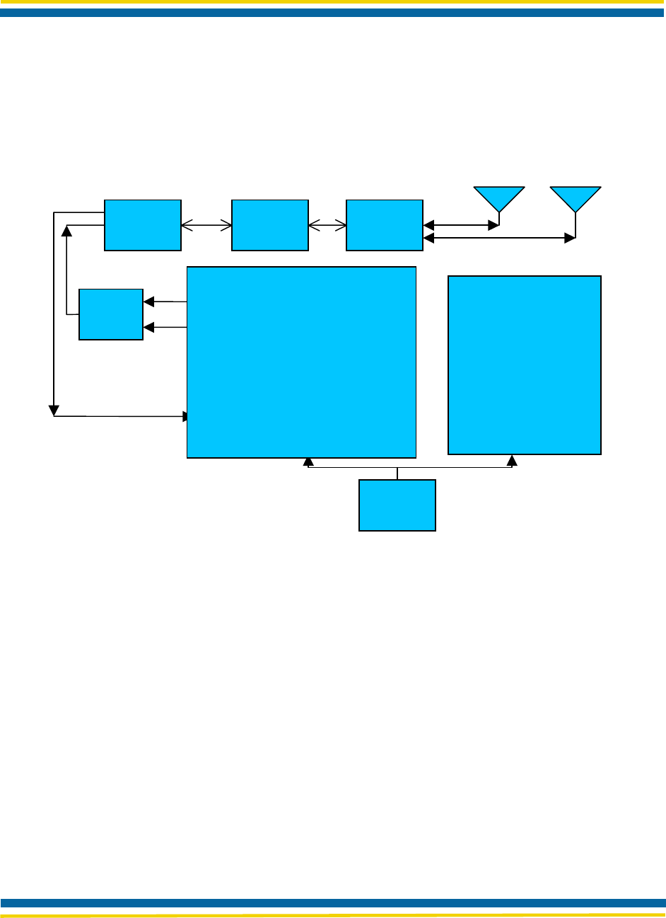
1.4 MODULE BLOCK DIAGRAM
Figure 1. Airborne™ Radio Module Block Diagram
1.5 USING THIS DOCUMENT
In addition to this chapter, this guide contains the following chapters and appendixes:
Chapter 2, Specifications
Chapter 3, Application
Appendix A, Radio Frequency Channels
Appendix B, Glossary
802.11 Baseband
Processor/Media
Access Controller
Balun
40MHz
clock
LNA
PA
Receiver
Frequency
S
y
nthesizer
Transmitter
VCO
Tx/Rx
Switch Bandpass
Filter Diversity
switch
88W8015 88W8385
Page 4 Airborne™ Wireless LAN Radio Module Data Book TBD
QUATECH Confidential Rev. A 6/12/2006
1.6 CONVENTIONS
1.6.1 Terminology
“Airborne(TM) Radio Module” identifies this Module the first time in a chapter. Thereafter, the term
“Module” is used.
1.6.2 Notes
A note is information that requires special attention. The following convention is used for notes.
Note
Note
A note contains information that deserves special attention.
1.6.3 Cautions
A caution contains information that, if not followed, can cause damage to the product or injury to the user.
The following convention is used for cautions.
Caution!
Caution!
A caution contains information that, if not followed, can cause damage to the product or
injury to the user.
1.7 RELATED DOCUMENTATION
The following related documentation is available on the Airborne™ Radio Evaluation Kit CD:
Airborne™ Radio Data Book TBD.
Airborne™ PCMCIA Adapter Reference Manual 39L3715-01
QUATECH Airborne Product briefs
The following related documentation is available from Marvell:
These documents are provided as Portable Document Format (PDF) files. To read them, you need Adobe
Acrobat Reader 4.0.5 or higher. For your convenience, Adobe Reader is provided on the Evaluation Kit
CD. For the latest version of Adobe Acrobat Reader, go to the Adobe Web site (www.adobe.com).
Please contact your local Marvell Sales Representative to locate referenced Marvell drawings and
documents or visit the Marvell website at www.marvell.com. Some of the referenced documents require

Page 5 Airborne™ Wireless LAN Radio Module Data Book TBD
QUATECH Confidential Rev. A 6/12/2006
Non-Disclosure Agreements and Developer Status with Marvell. QUATECH will not provide support for
any of the Marvell Reference documentation.
1.8 FCC STATEMENT
This equipment has been tested and found to comply with the limits for a Class B digital device, pursuant
to Part 15 of the FCC Rules. These limits are designed to provide reasonable protection against harmful
interference in a residential installation. This equipment generates uses and can radiate radio frequency
energy and if not installed and used in accordance with the instructions, may cause harmful interference to
radio communications. However, there is no guarantee that interference will not occur in a particular
installation. If this equipment does cause harmful interference to radio or television reception, which can
be determined by turning the equipment off and on, the user is encouraged to try to correct the
interference by one or more of the following measures:
Reorient or relocate the receiving antenna.
Increase the separation between the equipment and receiver.
Connect the equipment to an outlet on a circuit different from that to which the receiver is connected.
Consult the dealer or an experienced radio/TV technician for assistance.
Operation is subject to the following two conditions: (1) this device may not cause interference, and (2)
this device must accept any interference, including interference that may cause undesired operation of the
device
1.9 FCC RF EXPOSURE STATEMENT
To satisfy RF exposure requirements, this device and its antenna must operate with a separation distance
of a least 20 cm from all persons and must not be co-located or operating in conjunction with any other
antenna or transmitter.
1.10 INFORMATION FOR CANADIAN USERS (IC NOTICE)
This device has been designed to operate with an antenna having a maximum gain of 5dBi. An antenna
having a higher gain is strictly prohibited per regulations of Industry Canada. The required antenna
impedance is 50 ohms.
To reduce potential radio interference to other users, the antenna type and its gain should be so chosen
that the equivalent isotropically radiated power (EIRP) is not more than required for successful
communication.
Operation is subject to the following two conditions: (1) this device may not cause interference, and (2)
this device must accept any interference, including interference that may cause undesired operation of the
device
Airborne™ Wireless LAN Radio Module Data Book TBD
QUATECH Confidential Rev. A 6/12/2006
2.1 ELECTRICAL SPECIFICATIONS
Table 2. Electrical Supply Specifications for Airborne™ Radio Module
Specification Description
Supply 3.3 VDC
Power Up Inrush Current 3000 mA (max)
Clock Frequencies 802.11CPU reference clock 40 MHz
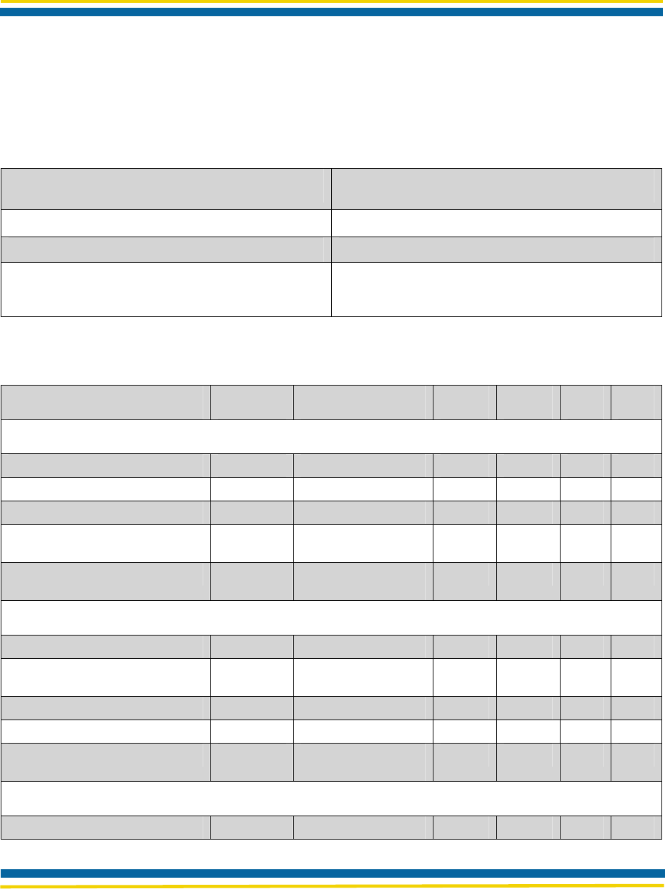
Table 3. Electrical Specifications for Airborne™ Radio Module
Parameter Symbol Test Conditions Min Typ Max Units
Current Consumption
Initialization Current ICC XX mA
Quiescent Current ICC XX mA
Continuous Transmit Mode ICC XX mA
Continuous Receive Mode ICC Receiving Valid
Packets XX mA
IEEE 802.11 Power Save Mode ICC RX On, 100 msec
Beacon Intervals XX mA
PCMCIA Logic Levels
Input HIGH Voltage VIH VCC=Max, Min 0.7VCC V
Input LOW Voltage VIL V
CC=Min, Max 0.3VC
C V
Output HIGH Voltage VOH IOL = 2mA, VCC=Min 2.6 V
Output LOW Voltage VOL I
OL = 2mA, VCC=Min 0.05 V
Input Leakage Current II VCC=Max, Input=0V
or VCC 0.1 1.0 µA
PCMCIA Loading Capacitance
Input Capacitance CIN 5 10 pF
CHAPTER 2
SPECIFICATIONS

Page 3 Airborne™ Wireless LAN Radio Module Data Book TBD
QUATECH Confidential Rev. A 6/12/2006
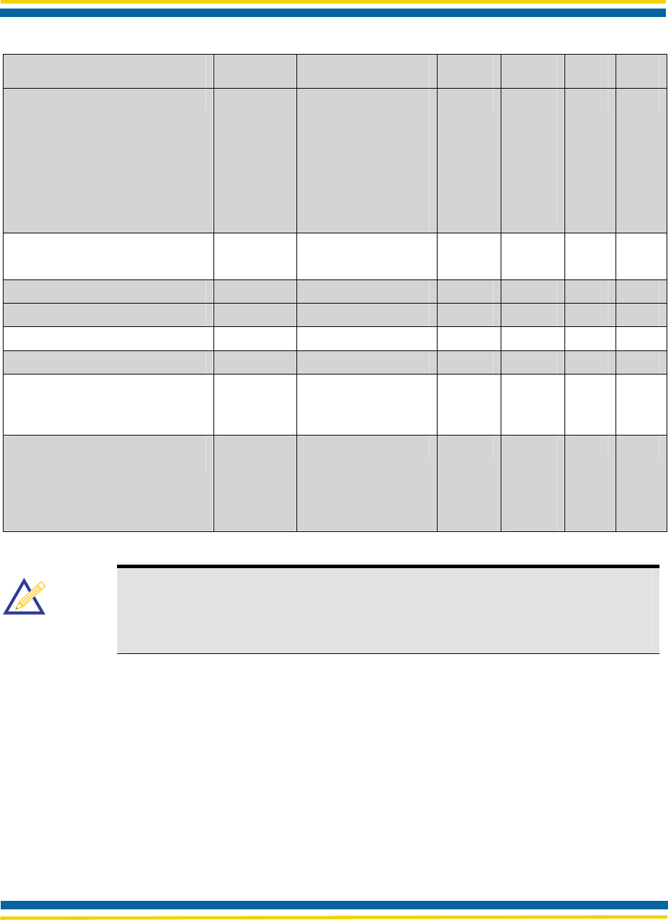
Parameter Symbol Test Conditions Min Typ Max Units
Output Capacitance COUT 5 10 pF
RF System Specifications
B-Mode Transmitter Power Output
G-Mode Transmitter Power Output
Pout 15
12
dBm
Receive Sensitivity RX_S 1 Mbps, 8% PER -87 dBm
2 Mbps, 8% PER -87 dBm
5.5 Mbps, 8% PER -86 dBm
11 Mbps, 8% PER
54Mbps, 10% PER
36Mbps, 10% PER
18Mbps, 10% Per
6Mbps, 10% PER
-85
XX
XX
XX
XX
dBm
Multipath Delay Spread Using TDELAY 1 Mbps, 8% PER >290 ns
IEEE 802.11 Naftali Model 2 Mbps, 8% PER >290 ns
5.5 Mbps, 8% PER 166 ns
11 Mbps, 8% PER
54Mbps, 10% PER
36Mbps, 10% PER
18Mbps, 10% Per
6Mbps, 10% PER
90
XX
XX
XX
XX
ns
Multipath Receive Sensitivity
Using JTC Models RX_SJTC 1 Mbps, 8% PER,
JTC
Commercial B (150
nsec)
-82 dBm
2 Mbps, 8% PER,
JTC Commercial B
(150 nsec)
-80 dBm
5.5 Mbps, 8% PER,
JTC Commercial B
(150 nsec)
-76 dBm
Page 4 Airborne™ Wireless LAN Radio Module Data Book TBD
QUATECH Confidential Rev. A 6/12/2006
Parameter Symbol Test Conditions Min Typ Max Units
11 Mbps, 8% PER,
JTC Office B
(100 nsec)
54Mbps, 10% PER
36Mbps, 10% PER
18Mbps, 10% Per
6Mbps, 10% PER
-67
XX
XX
XX
XX
dBm
Maximum Receive Level RX _MAX PER <8% (B-Mode)
PER <10% (G-Mode)
+3
-10
dBm
Third Order Intercept Point (Input) IIP3_90 -90 dBm input -3 dBm
IIP3_25 -25 dBm input 20 dBm
Carrier Suppression TX_sup Test Mode 42.5 dB
Image Rejection IR PER <8% 60 dB
Adjacent Channel Rejection ACR PER <8% B-
Mode(Note 2)
PER<10% G-Mode
46
XX
dB
Data Rate (Physical Layer) B-
Mode and G-Mode Rate 1, 2,
5.5, 11,
6, 9, 12,
18, 24,
36, 48,
54
Mbps
Note
Note
1. Test Conditions: Supply Voltage (VCC) = 3.3V, Ambient Temperature (TA) = 25oC,
unless otherwise specified.
2. The adjacent channel measurement is carried out on two channels separated by
25MHz (5 channels).
Page 5 Airborne™ Wireless LAN Radio Module Data Book TBD
QUATECH Confidential Rev. A 6/12/2006
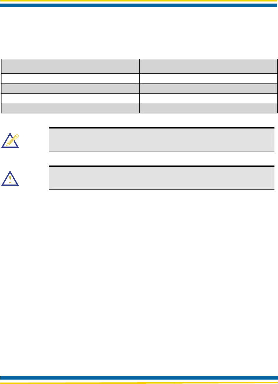
2.1.1 Absolute Maximum Ratings
Table 4. Absolute Maximum Ratings and Operating Environment
Specification Description
Supply Voltage Range 3.0V to 3.6V
Supply Voltage -0.3V to 4.0V (Max)
Temperature Range -40oC ~ TA ~ 85oC
Storage Temperature -55oC to 125oC
Note
Note
All temperature references refer to ambient conditions.
Caution!
Caution!
These are the absolute maximum ratings for the Airborne™ Radio Module.
Exceeding these limits could cause permanent damage to the card.
Page 6 Airborne™ Wireless LAN Radio Module Data Book TBD
QUATECH Confidential Rev. A 6/12/2006
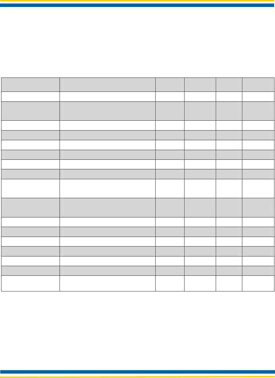
2.1.2 Electrical Characteristics
Table 5. Electrical Characteristics
Symbol Parameter Min Typ Max Unit
VDD Supply Voltage (3.3V ±5%) 3.135 3.3 3.465 V
IDDTX Transmit Mode Current (B-Mode)
G-Mode
450
475
500
525
mA
IDDRX Receive Mode Current 275 325 mA
IDDSLEEP Sleep Mode Current 100 200 mA
VIHGP GPIO Input High voltage 1.8 5.5 V
VILGP GPIO Input Low voltage 1.0 V
VOHGP GPIO Output High voltage 2.4 VDD V
VOLGP GPIO Output Low voltage 0.4 V
IOHGP GPIO Output High Current Port E5
and Port E6 only 24
60 mA
IOLGP GPIO Output Low Current Port E5
and Port E6 only 16
40 mA
VIHAn Analog Input High voltage 1.8 2.5 V
VILAN Analog Input Low voltage 1.0 V
VOHAn Analog Output High voltage 2.4 2.5 V
VOLAn Analog Output Low voltage 0.4 V
IOHAn Analog Output High Current 6 mA
IOLAn Analog Output Low Current 6 mA
SVDD D
VDD slew rate to ensure Power-On
reset 0.05 V/ms

Page 7 Airborne™ Wireless LAN Radio Module Data Book TBD
QUATECH Confidential Rev. A 6/12/2006
2.2 RADIO FREQUENCY SPECIFICATIONS
Table 6. Radio Frequency Specifications
Specification Description
RF Power +15 dBm (typical) Approx.32 mW for B-Mode and
+12dBm (typical) Approx 16mW for G-Mode
Sensitivity -82 dBm for 11 Mbps
-86 dBm for 5.5 Mbps
-88 dBm for 2 Mbps
-90 dBm for 1 Mbps
-71 dBm for 54Mbps
-77 dBm for 36Mbps
-83 dBm for 18Mbps
-xx dBm for 6Mbps
Frequency 2.4 – 2.4835 GHz (US/Canada/Japan/Europe)
2.471 – 2.497 GHz (Japan)
Modulation DQPSK, DBPSK, and CCK for B-Mode
BPSK, QPSK, 16-QAM, and 64-QAM for G-Mode
Channels USA/Canada: 11 channels (1 –11)
Europe: 13 channels (1 –13)
Japan: 14 channels (1 –14) for B-Mode and channels 1-
13 for G-Mode
France: 4 channels (10 –13)
2.2.1 AC Electrical Characteristics – Transmitter
Transmit power is automatically managed by the device for minimum power consumption. The transmit
power is typically +15 ± 2 dB for B-Mode and +12+/-2dB for G-Mode
2.2.2 Performance/Range
The following table illustrates the typical data rates, performance and range the device is capable of
providing using an omni directional antenna.
Page 8 Airborne™ Wireless LAN Radio Module Data Book TBD
QUATECH Confidential Rev. A 6/12/2006
Table 7. Performance/Range*
Data Rate Indoor Distance Outdoor Distance
(Max)
11.0 Mb/s 30 – 100 m 300 m
5.5 Mb/s 32 – 107 m 330 m
2.0 Mb/s 35 – 115 m 375 m
1.0 Mb/s 40 – 130 m 400 m
* Ranges are based on signal-to-noise ratio and performance estimates. Actual maximum throughput will
depend upon host performance.
Note
Note
Data Rate is the raw data rate provided over the wireless link.
Throughput is the data rate provided through the TCP/IP Stack.
Indoor Distance is “Office Environment”.
Outdoor Distance is “Open Field”.
2.3 INTERFACE SPECIFICATIONS
2.3.1 Interface Specifications
50 pin connector (PN: HRS DF12-50DS-0.5V)
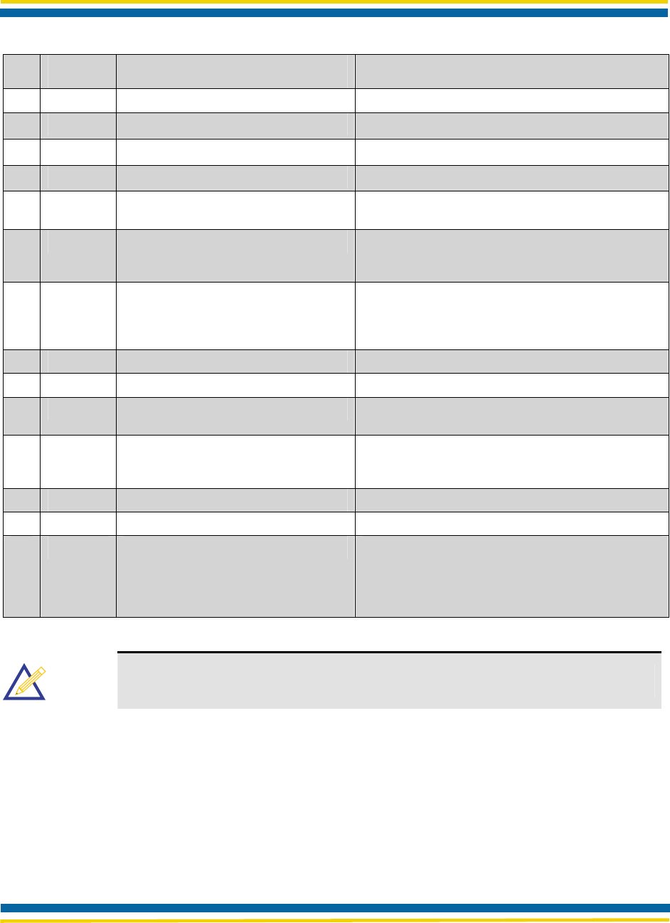
2.3.2 Pin Assignments
Table 8. Pin Assignments
Pin Signal Pin I/O Type Description
1 RF_VCC Power, 0.35A DC Power Supply 3.3V ±5%
2 RF_VCC Power, 0.35A DC Power Supply 3.3V ±5%
3 RF_VCC Power, 0.35A DC Power Supply 3.3V ±5%
4 RF_VCC Power, 0.35A DC Power Supply 3.3V ±5%
5 A00 5V tol, BiDir, 2mA, 50K Pull Down Host Address Input, Bits 0
6 D00 5V tol, BiDir, 2mA, 50K Pull Down Host Data Bus, Bits 0
7 A01 5V tol, BiDir, 2mA, 50K Pull Down Host Address Input, Bits 1

Page 9 Airborne™ Wireless LAN Radio Module Data Book TBD
QUATECH Confidential Rev. A 6/12/2006
Pin Signal Pin I/O Type Description
8 D01 5V tol, BiDir, 2mA, 50K Pull Down Host Data Bus, Bits 1
9 A02 5V tol, BiDir, 2mA, 50K Pull Down Host Address Input, Bits 2
10 D02 5V tol, BiDir, 2mA, 50K Pull Down Host Data Bus, Bits 2
11 A03 5V tol, BiDir, 2mA, 50K Pull Down Host Address Input, Bits 3
12 D03 5V tol, BiDir, 2mA, 50K Pull Down Host Data Bus, Bits 3
13 A04 5V tol, BiDir, 2mA, 50K Pull Down Host Address Input, Bits 4
14 D04 5V tol, BiDir, 2mA, 50K Pull Down Host Data Bus, Bits 4
15 A05 5V tol, BiDir, 2mA, 50K Pull Down Host Address Input, Bits 5
16 D05 5V tol, BiDir, 2mA, 50K Pull Down Host Data Bus, Bits 5
17 A06 5V tol, BiDir, 2mA, 50K Pull Down Host Address Input, Bits 6
18 D06 5V tol, BiDir, 2mA, 50K Pull Down Host Data Bus, Bits 6
19 A07 5V tol, BiDir, 2mA, 50K Pull Down Host Address Input, Bits 7
20 D07 5V tol, BiDir, 2mA, 50K Pull Down Host Data Bus, Bits 7
21 A08 5V tol, BiDir, 2mA, 50K Pull Down Host Address Input, Bits 8
22 GND Ground Digital Ground
23 A09 5V tol, BiDir, 2mA, 50K Pull Down Host Address Input, Bits 9
24 D08 5V tol, BiDir, 2mA, 50K Pull Down Host Data Bus, Bits 8
25 GND Ground Digital Ground
26 D09 5V tol, BiDir, 2mA, 50K Pull Down Host Data Bus, Bits 9
27 OE# 5V tol, BiDir, 2mA, 50K Pull Up Host Memory Attribute Space Output
Enable
28 D10 5V tol, BiDir, 2mA, 50K Pull Down Host Data Bus, Bits 10
29 WE# 5V tol, CMOS, Input, 50K Pull Up Host Memory Attribute Space Write Enable
30 D11 5V tol, BiDir, 2mA, 50K Pull Down Host Data Bus, Bits 11
31 IORD# 5V tol, BiDir, 2mA, 50K Pull Up Host I/O Space Read Strobe
32 D12 5V tol, BiDir, 2mA, 50K Pull Down Host Data Bus, Bits 12
33 IOWR# 5V tol, BiDir, 2mA, 50K Pull Up Host Space I/O Write Strobe
34 D13 5V tol, BiDir, 2mA, 50K Pull Down Host Data Bus, Bits 13
35 CE1# 5V tol, BiDir, 2mA, 50K Pull Up Host Select, Low Byte
36 D14 5V tol, BiDir, 2mA, 50K Pull Down Host Data Bus, Bits 14
Page 10 Airborne™ Wireless LAN Radio Module Data Book TBD
QUATECH Confidential Rev. A 6/12/2006
Pin Signal Pin I/O Type Description
37 CE2# 5V tol, BiDir, 2mA, 50K Pull Up Host Select, High Byte
38 D15 5V tol, BiDir, 2mA, 50K Pull Down Host Data Bus, Bits 15
39 GND Ground Digital Ground
40 GND Ground Digital Ground
41 RESET 5V tol, CMOS, ST (Schmitt Trigger)
Input, 50K Pull Up Hardware Reset
42 IREQ# 5V tol, BiDir, 2mA, 50K Pull Up Host interrupt Request (I/O Mode), also used as the
Module’s Ready (Memory Mode) output which is
asserted to indicate Module initialization is complete
43 REG# 5V tol, BiDir, 2mA, 50K Pull Up Host Attribute Space Select Memory mode: H for
common memory, L for attribute memory. The
signal must be low during I/O cycles when the I/O
address is on the bus.
44 WAIT# CMOS Output, 4mA, 10K Pull Up Host device must provide a 10K Pull Up
45 RF_LED# Input, 9mA LED cathode
46 IOIS16# Pull Low, Output 8 Bits or 16 Bits I/O Card selected
L: 16 bit or odd byte only operation
47 STSCHG# CMOS Output, 4mA 50K Pull Up Host Status Change
Shows the BVD1 (Battery Voltage Detect), BVD2,
WP (Write Protect), or Ready status changed.
48 CD1# Pull Low, Output Card Detect
49 GND Ground Digital Ground
50 INPACK# CMOS BiDir, 2mA, 50K Pull Up Host I/O Decode Confirmation. Asserted by the
Module when selected and responding to an I/O
read
cycle. Used to control the HBA (Host Bus Adaptor)
tri-state buffer on/off).
Note
Note
The interface is a subset of a PC Card interface.
2.3.3 Pin Features*
The following describes specific features of various pins:

Page 11 Airborne™ Wireless LAN Radio Module Data Book TBD
QUATECH Confidential Rev. A 6/12/2006
Table 9 - Pin Definition and Descriptions
Pin feature Description
A[9:0] Decoding of the system address space is performed by the CEx-. During I/O accesses
A[5:0] decode the register. A[9:6] are ignored when the internal HAMASK register is set
to the defaults used by the standard firmware. During attribute memory accesses A[9:1]
are used.
D[15:0] The host interface is primarily designed for word accesses, although all byte access
modes are fully supported. See CE1-, CE2- for a further description. Note that attribute
memory is specified for and operates with even bytes accesses only.
CE1-, CE2- The PC Card cycle type and width are controlled with the CE signals. Word and Byte
wide accesses are supported, using the combinations of HCE1-, HCE2-, and HA0 as
specified in the PC Card standard.
WE-, OE HOE and HWE- are only used to access attribute memory. Common Memory, as
specified in the PC Card standard, is not used in the MODULE. HOE- is the strobe that
enables an attribute memory read cycle. HWE- is the corresponding strobe for the
attribute memory write cycle. The attribute space contains the Card Information
Structure (CIS) as well as the Function Configuration Registers (FCR).
IORD-, IOWR IORD-and HIOWR- are the enabling strobes for register access cycles to the MODULE.
These cycles can only be performed once the initialization procedure is complete and
the MODULE has been put into IO mode.
REG This signal must be asserted for I/O or attribute cycles. A cycle where HREG- is not
asserted will be ignored as the MODULE does not support common memory.
INPACK This signal is asserted by the MODULE whenever a valid I/O read cycle takes place. A
valid cycle is when HCE1-, HCE2-,- HREG-, and HIORD- are asserted, once the
initialization procedure is complete.

Page 12 Airborne™ Wireless LAN Radio Module Data Book TBD
QUATECH Confidential Rev. A 6/12/2006
Pin feature Description
WAIT Wait states are inserted in accesses using HWAIT-. The host interface synchronizes all
PC Card cycles to the internal MODULE clock. The following wait states should be
expected:
Direct Read or Write to Hardware Register
• 1/2 to 1 MCLK assertion of HWAIT- for internal synchronization. Write to Memory
Mapped Register, Buffer Access Path, or Attribute Space (Post-Write)
• The data required for the write cycle will be latched and therefore only the
synchronizing wait state will occur.
• Until the queued cycle has actually written to the memory, any subsequent access by
the Host will result in a WAIT.
Read to Attribute Space and Memory Mapped Registers
• WAIT will assert until the memory arbitration and access have completed.
Buffer Access Paths, BAP0 and BAP1
• An internal Pre-Read cycle to memory is initiated by a host Buffer Read cycle, after the
internal address pointer has auto-incremented. If the next host cycle is a read to the
same buffer, the data will be available without a memory arbitration delay.
• A single register holds the pre-read data. Thus, any read access to any other memory-
mapped register (or the other buffer access path) would result in the pre-read data
becoming invalidated.
• If another read cycle has invalidated the pre-read, then a memory arbitration delay will
occur on the next buffer access path read cycle.
IREQ Immediately after reset, the HIREQ- signal serves as the RDY/BSY (per the PC Card
standard). Once the MODULE firmware initialization procedure is complete, HIREQ- is
configured to operate as the interrupt to the PC Card socket controller. Both Level Mode
and Pulse Mode interrupts are supported. By default, Level mode interrupts are used,
so the interrupt source must be specifically acknowledged or disabled before the
interrupt will be removed.
Register Interface The logical view of the MODULE from the host is a block of 32-word wide registers.
These appear in IO space starting at the base address determined by the socket
controller.
Hardware Registers
(HW) • 1 to 1 correspondence between addresses and registers.
• No memory arbitration delay, data transfer directly to/from registers.
• AUX base and offset are write-only, to set up access through AUX data port.
Note
Note
All register cycles, including hardware registers, incur a short wait state
on the PC Card bus to insure the host cycle is synchronized with the
MODULE's internal MCLK.

Page 13 Airborne™ Wireless LAN Radio Module Data Book TBD
QUATECH Confidential Rev. A 6/12/2006
2.3.4 Antenna Pin Assignments and Descriptions
Figure 2. Antenna Connectors
Table 10. Airborne™ Radio Module Antenna Pin Assignments
Assignment Description
J1 (left connector) Antenna 1
J2 (right connector) Antenna 2
Page 14 Airborne™ Wireless LAN Radio Module Data Book TBD
QUATECH Confidential Rev. A 6/12/2006
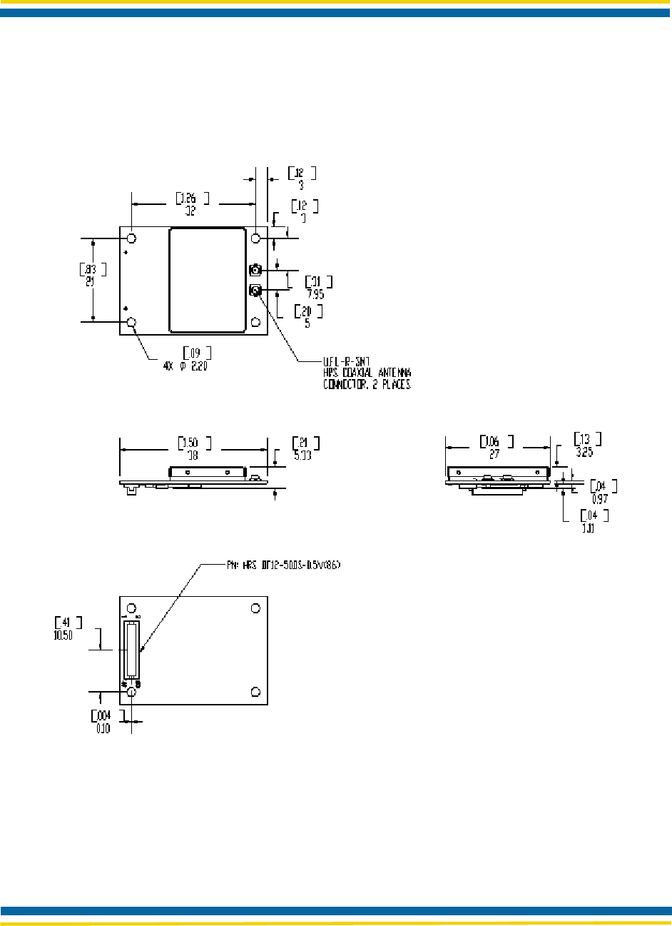
2.4 MECHANICAL SPECIFICATIONS
Figure 3. Mechanical Dimensions
Airborne™ Wireless LAN Radio Module Data Book TBD
QUATECH Confidential Rev. A 6/12/2006
3.1 DESIGN GUIDELINES
The Module can be implemented into various solutions. Any design must meet the following guidelines:
Provide 3.3 V to all Vdd power pins.
Provide ground connections to all Vss pins.
Provide a connection to a suitable antenna.
Caution!
Caution!
The 3.3 V power supply should be a low-noise design, with less than 150 mV ripple at the
maximum average transmit current. The power supply should also be designed to provide
sufficient power to handle the Module’s power-up inrush current.
3.2 EMI/RFI GUIDELINES
To minimize electromagnetic interference (EMI) and radio frequency interference (RFI), pay strict
attention to power and signal routing near the Module. As much as possible, the keep-clear area
below the Module should be a solid copper ground plane. It is anticipated that the Module will be
mounted on a board with a committed ground plane. Ensure the inter-connect has a designed
impedance of 50-75 Ohms.
To keep signal impedance as low as possible, connect the ground plane to internal ground planes
by several vias. Ground signals to the Module connector should connect directly to the ground
plane below the Module. Individual ground connections to the Module should have a solid ground
connection, preferably directly to the ground plane on the same surface side where the Module
resides. Do not connect ground pins directly to an inside layer ground plane using vias.
Keep interconnects from the Module connector as short as possible on the mounting layer. All
inboard signals–including pin numbers–must immediately transition to a different routing layer
using a via as close to the connector as possible. Outboard signals (odd pin numbers) should also
be kept to a minimum length.
3.3 CIRCUIT BOARD LAYOUT PRACTICES
When considering capacitance, calculations must consider all device loads and capacitances due
to printed circuit board traces. Capacitance due to the traces depend on a number of factors,
including the trace width, dielectric material from which the circuit board is made, and proximity to
ground and power planes.
CHAPTER 3
APPLICATION
Page 16 Airborne™ Wireless LAN Radio Module Data Book TBD
QUATECH Confidential Rev. A 6/12/2006
inch [mm]
1.17 [29.7]
0.83 [21.1]
1.60 [40.6]
0.17 [4.3]
1.26 [32.0]
0.01[0.2]
0.17 [4.3]
0.41[10.5]
3XØ0.09 [Ø2.2]
THIS AREA CLEAR
FROM INTERCONNECT
AND COMPONENTS
2
50
1
49
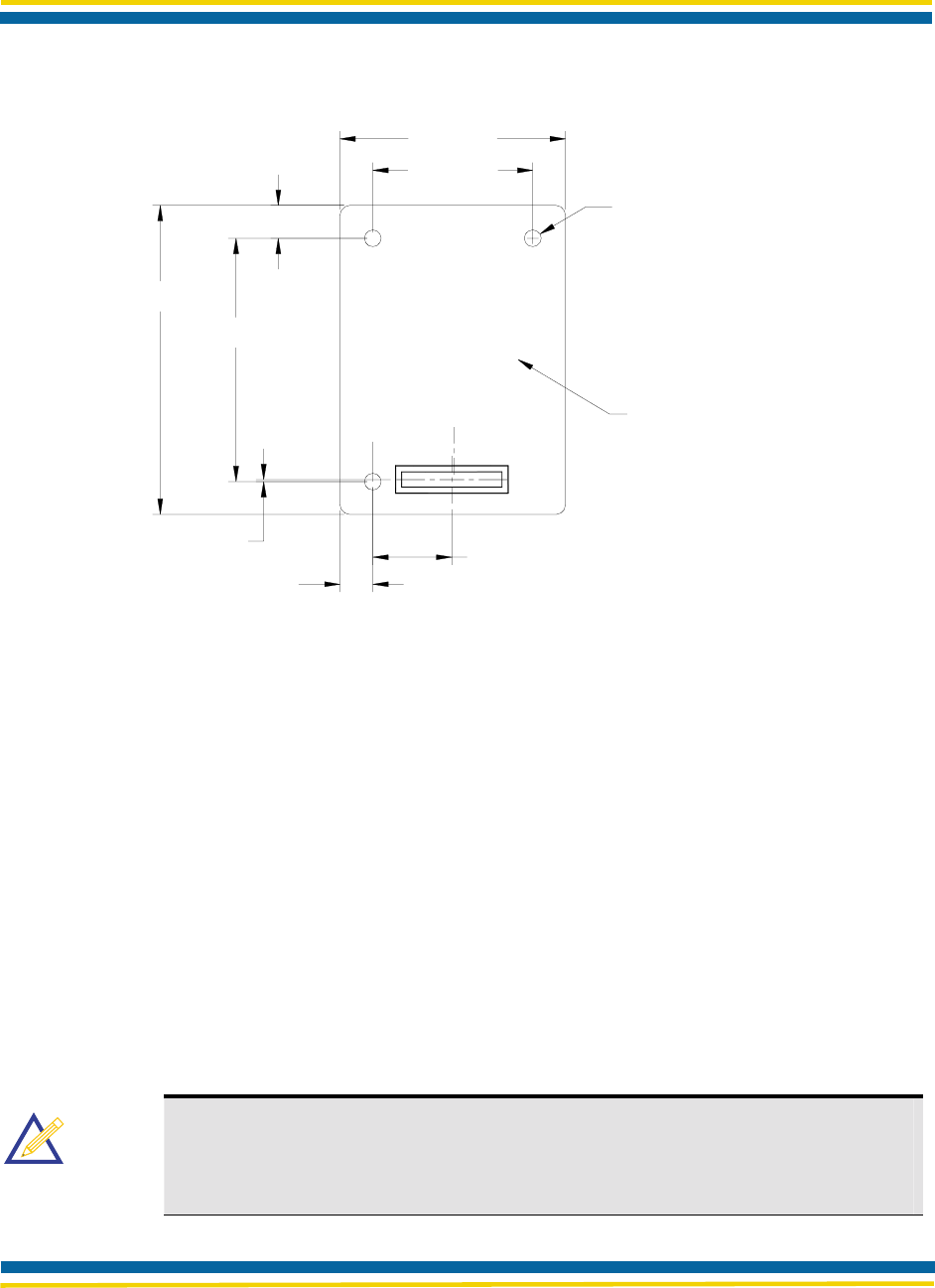
Figure 4. Guidelines for Mounting the Radio Module
3.4 MOUNTING GUIDELINES
Special care must be observed when placing the Module. In particular:
The antenna must not be mounted beneath any other printed circuit boards, components, or
metallic housing.
The proximity of the antenna to large metallic objects can affect the range and performance of
the Module.
Packaging and enclosure designers must carefully review the placement of the Module in the
enclosure to minimize interference or blocking sources.
For mechanical clearance, performance, and emissions reasons, there should be no components
placed on the main printed circuit board facing the Module. This region should be clear of
components.
Note
Note
Suggested mounting: Use three non conductive spacers with the following
dimensions:
O/D Diameter 0.187 x I/D Diameter 0.096 x Length 0.156

Page 17 Airborne™ Wireless LAN Radio Module Data Book TBD
QUATECH Confidential Rev. A 6/12/2006
Airborne™ Wireless LAN Radio Module Data Book TBD
QUATECH Confidential Rev. A 6/12/2006
A.1. USING RADIO FREQUENCIES
IEEE 802.11 devices such as the Airborne™ Radio Module use radio-frequency signals in the
Industrial, Scientific, and Medical (ISM) band between 2.4 GHz and 2.5 GHz to communicate with
each other.
Due to spread spectrum effect of the signals, a radio sending signals on a particular channel uses
the frequency spectrum 12.5 MHz above and below the center channel frequency. As a result, two
separate WLANs in the same general vicinity that use neighboring channels (channel 1 and
channel 2, for instance) can interfere with each other. Applying two channels that allow the
maximum channel separation decreases the amount of channel cross-talk and provides
performance gains over networks with minimal channel separation.
The preferred channel separation between the channels in neighboring wireless networks is 25
MHz (5 channels). Neighboring channels are 5 MHz apart. To minimize adjacent channel
interference, you can apply a maximum of three different channels within your WLAN. There are
11 usable wireless channels in the United States. It is recommended that you start using channel
1 and grow to use channel 6, and 11 when necessary, as these three channels do not overlap.
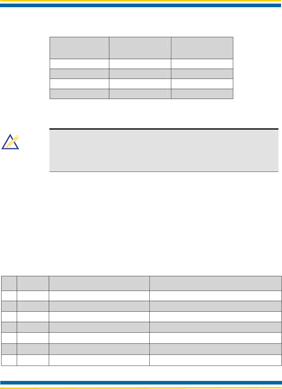
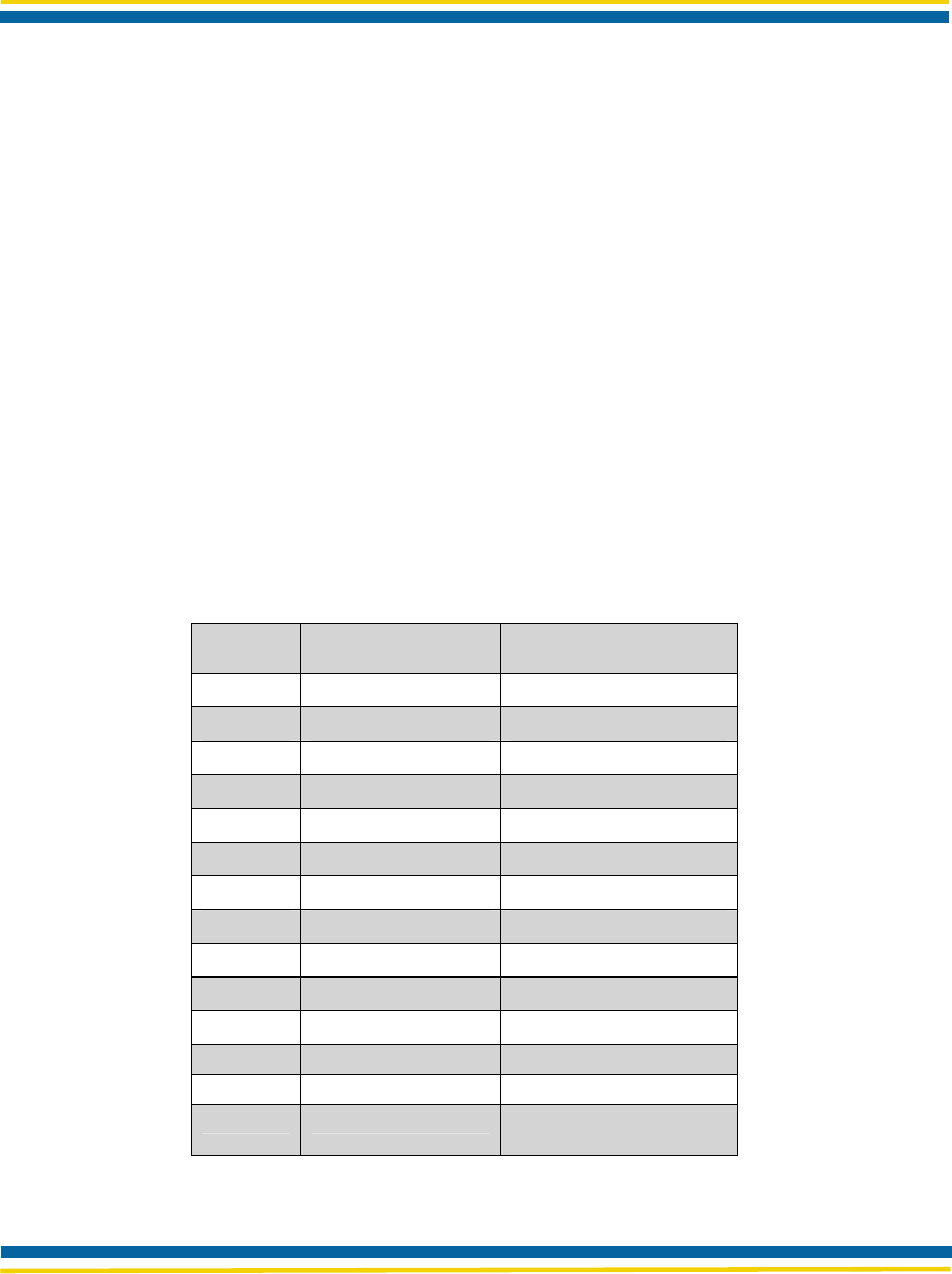
The following chart lists the 802.11 radio-frequency channels that are used.
Table 11. Radio Frequency Channels
Channel Center Frequency Frequency Spread
1 2412 MHz 2399.5 MHz - 2424.5 MHz
2 2417 MHz 2404.5 MHz - 2429.5 MHz
3 2422 MHz 2409.5 MHz - 2434.5 MHz
4 2427 MHz 2414.5 MHz - 2439.5 MHz
5 2432 MHz 2419.5 MHz - 2444.5 MHz
6 2437 MHz 2424.5 MHz - 2449.5 MHz
7 2442 MHz 2429.5 MHz - 2454.5 MHz
8 2447 MHz 2434.5 MHz - 2459.5 MHz
9 2452 MHz 2439.5 MHz - 2464.5 MHz
10 2457 MHz 2444.5 MHz - 2469.5 MHz
11 2462 MHz 2449.5 MHz - 2474.5 MHz
12 2467 MHz 2454.5 MHz - 2479.5 MHz
13 2472 MHz 2459.5 MHz - 2484.5 MHz
14 2484 MHz 2471.5 MHz – 2496.5
MHz
APPENDIX A:
RADIO FREQUENCY CHANNELS
Page 19 Airborne™ Wireless LAN Radio Module Data Book TBD
QUATECH Confidential Rev. A 6/12/2006
A.2. AUTHORIZED FREQUENCY CHANNELS BY REGION
International wireless frequency standards are a result of an IEEE 802.11WLAN committee
agreement. These standards enable the wireless data communication industry to develop
interoperable, low-cost, integrated equipment such as the Airborne™ Radio Module.
Authorized frequency channels vary by geographic region. The United States, Canada, Japan,
Spain, France, and the ETSI, or remaining European countries, each have their own authorized
frequencies.
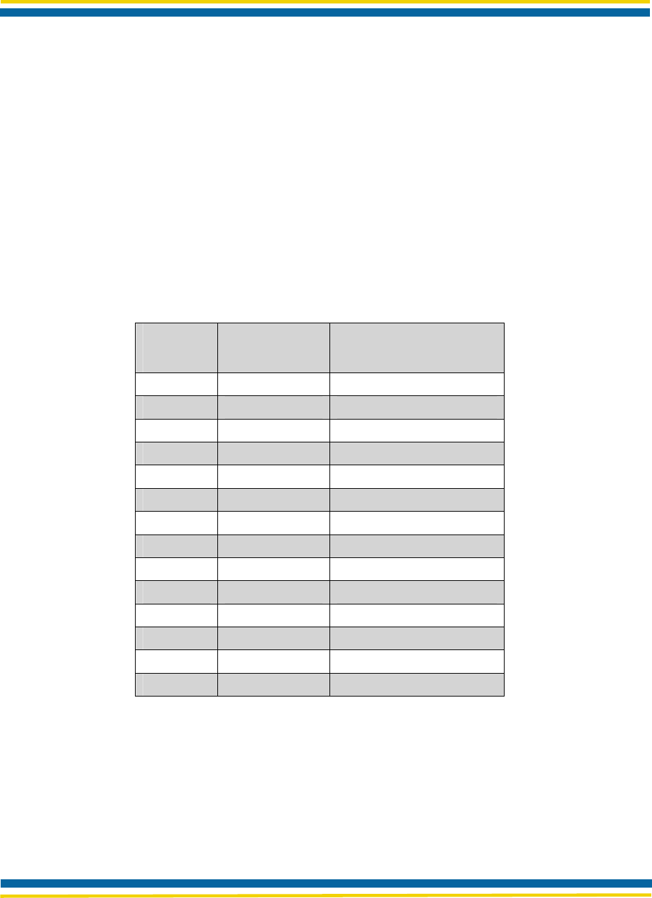
The following table illustrates authorized channels of operation according to geographic region.
Though this list is believed to be accurate at time of publication, consult local regulatory authorities
before using these channels of operation.
Table 12. IEEE 802.11 Channels
Channel
Number Channel
Frequency Geographic
Region
1 2412MHz US, CA, ETSI, MKK
2 2417MHz US, CA, ETSI, MKK
3 2422MHz US, CA, ETSI, MKK
4 2427MHz US, CA, ETSI, MKK
5 2432MHz US, CA, ETSI, MKK
6 2437MHz US, CA, ETSI, MKK
7 2442MHz US, CA, ETSI, MKK
8 2447MHz US, CA, ETSI, MKK
9 2452MHz US, CA, ETSI, MKK
10 2457MHz US, CA, ETSI, MKK, FR, SP
11 2462MHz US, CA, ETSI, MKK, FR, SP
12 2467MHz ETSI, FR, MKK
13 2472MHz ETSI, FR, MKK
14 2484MHz MKK
US = United States, CA = Canada, ETSI = European
countries (except France and Spain), FR = France,
SP = Spain, MKK = Japan
The Airborne™ Radio Module Firmware is FCC Compliant. You must use region-compliant
firmware that restricts channel access, such as ETSI-compliant firmware. Because the end user
does not have the ability to alter this firmware, regulatory compliance is ensured.

Page 20 Airborne™ Wireless LAN Radio Module Data Book TBD
QUATECH Confidential Rev. A 6/12/2006
This appendix provides a glossary of wireless terminology.
802.11 Wireless standards developed by the IEEE that
specify an "over-the-air" interface for wireless Local
Area Networks. 802.11 is composed of several
standards operating in different radio frequencies.
802.11a 802.11a is an IEEE specification for wireless
networking that operates in the 5 GHz frequency range
(5.725 GHz to 5.850 GHz) with a maximum 54 Mbps
data transfer rate. The 5 GHz frequency band is not as
crowded as the 2.4 GHz frequency, because the
802.11a specification offers more radio channels than
the 802.11b/g. These additional channels can help
avoid radio and microwave interference.
802.11b 802.11b is the international standard for wireless
networking that operates in the 2.4 GHz frequency
range (2.4 GHz to 2.4835 GHz) and provides a
throughput of up to 11 Mbps.
802.11g 802.11g is similar to 802.11b, but this forthcoming
standard provides a throughput of up to 54 Mbps. It
also operates in the 2.4 GHz frequency band but uses
OFDM radio technology in order to boost overall
bandwidth.
Access Point An interface between a wireless network and a wired
network Access Points can combine with a distribution
system such as Ethernet to create multiple radio cells
(BSSs) that enable roaming throughout a facility.
Ad-Hoc mode A wireless network composed of only stations and no
Access Point.
Association service An IEEE 802.11 service that an enables the mapping
of a wireless station to the distribution system via an
Access Point.
Asynchronous transmission Type of synchronization where there is no defined time
relationship between transmission of frames.
Authentication The process a station uses to announce its identify to
another station. IEEE 802.11 specifies two forms of
authentication: open system and shared key.
Bandwidth The amount of transmission capacity available on a
network at any point in time. Available bandwidth
depends on several variables such as the rate of data
transmission speed between networked devices,
network overhead, number of users, and the type of
device used to connect PCs to a network.
Basic Service Set (BSS) A set of 802.11-compliant stations that operate as a
connected wireless network.
APPENDIX B:
GLOSSARY

Page 21 Airborne™ Wireless LAN Radio Module Data Book TBD
QUATECH Confidential Rev. A 6/12/2006
Bits per second (bps) A measurement of data transmission speed over
communication lines based on the number of bits that
can be sent or received per second.
BSSID Basic Service Set Identifier. A 48-bit identifier used by
all stations in a BSS in frame headers. Usually MAC
address.
Clear channel assessment A function that determines the state of the wireless
medium in an IEEE 802.11 network.
Client Any computer connected to a network that requests
services (files, print capability) from another member
of the network.
Command Line Interface (CLI) A method of interacting with the Airborne WLN Module
by sending it typed commands.
Direct sequence spread spectrum (DSSS) Combines a data signal at the sending station with a
higher data rate bit sequence, which many refer to as
a chip sequence (also known as processing gain). A
high processing gain increases the signal’s resistance
to interference. The minimum processing gain that the
FCC allows is 10, and most products operate under
20.
Disassociation service An IEEE 802.11 term that defines the process a
station or Access Point uses to notify that it is
terminating an existing association.
Distribution service An IEEE 802.11 station uses the distribution service to
send MAC frames across a distribution system.
GPIO General Purpose Input/Output refers to the digital I/O
lines.
Host application The environment within which the Module is
embedded - typically includes a processor, which
forms part of an OEM’s product and application.
Hot spot Same as an Access Point, usually found in public
areas such as coffee shops and airports.
IEEE Institute of Electrical and Electronic Engineers, an
international organization that develops standards for
electrical . The organization uses a series of numbers,
like the Dewey Decimal system in libraries, to
differentiate between the various technology families.
Independent Basic Service Set Network
(IBSS Network) An IEEE 802.11-based wireless network that has no
backbone infrastructure and consists of at least two
wireless stations. This type of network is often referred
to as an Ad-Hoc network because it can be
constructed quickly without too much planning.

Page 22 Airborne™ Wireless LAN Radio Module Data Book TBD
QUATECH Confidential Rev. A 6/12/2006
Infrastructure mode A client setting providing connectivity to an Access
Point. As compared to Ad-Hoc mode, whereby PCs
communicate directly with each other, clients set in
Infrastructure mode all pass data through a central
Access Point. The Access Point not only mediates
wireless network traffic in the immediate
neighborhood, but also provides communication with
the wired network. See Ad-Hoc and AP.
LAN application A software application that runs on a computer, which
is attached to a LAN, Intranet or the Internet, and
using various protocols can communicate with the
Module.
Local Area Network A system of connecting PCs and other devices within
the same physical proximity for sharing resources
such as Internet connections, printers, files and drives.
When Wi-Fi is used to connect the devices, the
system is known as a wireless LAN or WLAN.
Medium Access Control Layer One of two sub-layers that make up the Data Link
Layer of the OSI reference model. The MAC layer is
responsible for moving data packets to and from one
network node to another across a shared channel.
MPDU MAC Protocol Data Unit, the unit of data exchanged
between two peer MAC entities using the services of
the physical layer (PHY).
MSDU MAC Service Data Unit, information that is delivered
as a unit between MAC service Access Points (SAPs).
Peer-to-peer network A wireless or wired computer network that has no
server or central hub or router. All the networked PCs
are equally able to act as a network server or client,
and each client computer can talk to all the other
wireless computers without having to go through an
Access Point or hub. However, since there is no
central base station to monitor traffic or provide
Internet access, the various signals can collide with
each other, reducing overall performance.
RS-232 An EIA standard that specifies up to 20 Kbps, 50 foot,
serial transmission between computers and peripheral
devices.
RTOS An operating system implementing components and
services that explicitly offer deterministic responses,
and therefore allow the creation of real-time systems.
An RTOS is characterized by the richness of the
services it provides, the performance characteristics of
those services, and the degree that those performance
characteristics can be controlled by the application
engineer ( to satisfy the requirements of the
application).

Page 23 Airborne™ Wireless LAN Radio Module Data Book TBD
QUATECH Confidential Rev. A 6/12/2006
Service Set Identifier (SSID) An identifier attached to packets sent over the wireless
LAN that functions as a "password" for joining a
particular radio network (BSS). All radios and Access
Points within the same BSS must use the same SSID,
or their packets will be ignored.
Telnet A virtual terminal protocol used in the Internet,
enabling users to log into a remote host.
Transceiver A device for transmitting and receiving packets
between the computer and the medium.
Transmission Control Protocol (TCP) A commonly used protocol for establishing and
maintaining communications between applications on
different computers. TCP provides full-duplex,
acknowledged, and flow-controlled service to upper-
layer protocols and applications.
Wide Area Network (WAN) A communication system of connected PCs and other
computing devices across a large local, regional,
national or international geographic area. Also used to
distinguish between phone-based data networks and
Wi-Fi. Phone networks are considered WANs and Wi-
Fi networks are considered wireless LANs.
Wi-Fi Wirekless-Fidelity: Wi-Fi is the common name used
for 802.11 wireless network technology.
Wi-Fi Alliance A non-profit international association formed in 1999
to certify interoperability of wireless LAN products
based on IEEE 802.11 specification.
Wired Equivalent Privacy (WEP) A security protocol for wireless LANs defined in the
IEEE 802.11 standard. WEP is designed to provide
the same level of security as a wired LAN.
WLAN Also referred to as a wireless LAN. A type of local-
area network that uses high-frequency radio waves
rather than wires to communicate between nodes and
provide network connectivity.

Airborne™ Wireless LAN Radio Module Data Book TBD
QUATECH Confidential Rev. A 6/12/2006
INDEX
A
AC electrical characteristics, transmitter, 11
Adobe Web site, 5
Airborne Radio Module
baseband processor features, 2
firmware, 23
medium access controller features, 2
overview, 1
radio features, 2
specifications, 18
Antenna pin assignments, 17
Authorized frequency channels, 23
B
Block diagram, 3
C
Capacitance, 19
Circuit board layout practices, 19
Compact Flash interface, 1
Conexant Web site, 5
Configurations, 1
Conventions, manual, 4
D
Design guidelines, 19
Documentation, 4
E
Electrical characteristics, 10
Electrical specifications, 7
Electromagnetic interference, 19
EMI/RFI guidelines, 19
F
FCC compliance, 23
Features
Airborne Radio Module, 1
baseband processor, 2
medium access controller, 2
pin, 14
Firmware, 23
Frequency channels, authorized, 23
G
Glossary, 24
Ground pins, 19
Guidelines
design, 19
EMI/RFI, 19
mounting, 20
I
Interface specifications, 12
Interference
electromagnetic, 19
radio frequency, 19
L
Layout practices, circuit board, 19
M
Media Access Controller, 1
Mounting guidelines, 20
P
Performance/range, 11
Pin
assignments, 12
features, 14
numbers, 19
Pin assignments, antenna, 17
Power supply, 12
Power-up, 19
R
Radio frequencies, using, 22
Radio frequency interference, 19
Radio frequency specifications, 11
S
Specifications, 7
interface, 12
mechanical, 18
performance/range, 11
radio frequency, 11

Airborne™ Wireless LAN Radio Module Data Book TBD
QUATECH Confidential Rev. A 6/12/2006
V
Vias, 19

Airborne™ Wireless LAN Radio Module Data Book TBD
QUATECH Confidential Rev. A 6/12/2006
QUATECH Confidential
5675 Hudson Industrial Parkway
Hudson, OH 44236
Tel: 330-655-9000
www.Quatech.com