B plus B SmartWorx WLNG1 WLRG-RA-DP101 User Manual
B&B; Electronics WLRG-RA-DP101
Contents
- 1. Users Manual
- 2. User Manual
User Manual

Product Databook
Airborne 802.11b/g Value Radio
WLRG-RA-DP101
Revision 1.0
December 2007
File name: 100-8026-100g 802.11bg value radio databook 1.0

Quatech, Inc. Company Confidential
Revision 1.0 100-8026-100G Airborne 802.11b/g Value Radio Databook 3
Quatech Confidential
Copyright © 2007 QUATECH ® Inc.
ALL RIGHTS RESERVED. No part of this publication may be copied in any form, by photocopy, microfilm, retrieval
system, or by any other means now known or hereafter invented without the prior written permission of QUATECH ® Inc..
This document may not be used as the basis for manufacture or sale of any items without the prior written consent of
QUATECH Inc..
QUATECH Inc. is a registered trademark of QUATECH Inc..
Airborne™ is a trademark of QUATECH Inc..
All other trademarks used in this document are the property of their respective owners.
Disclaimer
The information in the document is believed to be correct at the time of print. The reader remains responsible for the
system design and for ensuring that the overall system satisfies its design objectives taking due account of the information
presented herein, the specifications of other associated equipment, and the test environment.
QUATECH ® Inc. has made commercially reasonable efforts to ensure that the information contained in this document is
accurate and reliable. However, the information is subject to change without notice. No responsibility is assumed by
QUATECH for the use of the information or for infringements of patents or other rights of third parties. This document is
the property of QUATECH ® Inc. and does not imply license under patents, copyrights, or trade secrets.
Quatech, Inc. Headquarters
QUATECH ® Inc..
5675 Hudson Industrial Parkway
Hudson, OH 44236
USA
Telephone: 330-655-9000
Toll Free: 800-553-1170
Fax: 330-655-9010
Technical Support: 714-899-7543 / wirelesssupport@quatech.com
Web Site: www.quatech.com

Company Confidential Quatech, Inc.
4 100-8026-100G Airborne 802.11b/g Value Radio Databook Revision 1.0
Contents
Product Databook......................................................................................................................................... 2
1.0 Overview............................................................................................................................................ 6
2.0 Conventions....................................................................................................................................... 7
2.1 Terminology............................................................................................................................... 7
2.2 Notes .......................................................................................................................................... 7
2.3 Caution....................................................................................................................................... 7
2.4 File Format................................................................................................................................. 7
3.0 Product Description............................................................................................................................ 8
3.1 General Features...................................................................................................................... 8
3.2 Radio Features.......................................................................................................................... 8
3.3 Medium Access Controller and Baseband Processor Features........................................ 9
4.0 Block Diagrams.................................................................................................................................10
5.0 Model Numbers ................................................................................................................................11
6.0 Pin out and Connectors ....................................................................................................................12
7.0 Electrical & RF Specification.............................................................................................................15
7.1 AC Electrical Characteristics – Transmitter ........................................................................ 20
7.2 Performance/Range ............................................................................................................... 20
8.0 Antenna ............................................................................................................................................21
8.1 Antenna Selection................................................................................................................... 21
8.2 Host Board Mounted Antenna .............................................................................................. 21
8.3 Host Chassis Mounted Antenna........................................................................................... 22
8.4 Embedded Antenna................................................................................................................ 22
8.5 Antenna Location.................................................................................................................... 23
8.6 Performance............................................................................................................................ 24
9.0 Mechanical Outline ...........................................................................................................................26
10.0 Drivers and Software ........................................................................................................................27
11.0 Integration Guidelines.......................................................................................................................28
11.1 General Requirements........................................................................................................... 28
11.2 Power Supply Guidelines ...................................................................................................... 28
11.3 EMI/EMF Guidelines .............................................................................................................. 28
11.4 Circuit Board Layout Guidelines........................................................................................... 29
11.5 Mounting Guidelines............................................................................................................... 29
11.6 RESET Timer Guidelines ...................................................................................................... 30
12.0 Certification & Regulatory Approvals ................................................................................................31
12.1 FCC Statement ....................................................................................................................... 31
12.2 FCC RF Exposure Statement ............................................................................................... 31
12.3 Information for Canadian Users (IC Notice)........................................................................ 32
12.4 FCC/IOC Modular Approval .................................................................................................. 32
13.0 Physical & Environmental Approvals (Preliminary) ...........................................................................34
14.0 Glossary............................................................................................................................................35
15.0 Change Log ......................................................................................................................................38

Quatech, Inc. Company Confidential
Revision 1.0 100-8026-100G Airborne 802.11b/g Value Radio Databook 5
Figures
Figure 1- WLRG Radio ................................................................................................................................... 9
Figure 2 - Block Diagram for WLRG-RA-DP101 ............................................................................................10
Figure 3 – J1 - 50 pin Connector Layout (WLRG-RA-DP101) – Viewed from Bottom ...................................12
Figure 4 - WLRG-RA-DP101 Family Mechanical Outline...............................................................................26
Figure 5 - WLRG-RA-DP101 Mounting Footprint...........................................................................................29
Figure 6 - RESET Pulse Timing.....................................................................................................................30
Tables
Table 1 - Model Numbers...............................................................................................................................11
Table 2 – WLRG-RA-DP101 (PC16) Pin Definition........................................................................................13
Table 3- Absolute Maximum Values1.............................................................................................................15
Table 4 – Operating Conditions & DC Specification.......................................................................................16
Table 5 - PC16 (Compact Flash) Interface Specification ...............................................................................17
Table 6 - Supported Data Rates by Band ......................................................................................................17
Table 7 - Operating Channels........................................................................................................................18
Table 8 - RF Characteristics – 802.11b/g ......................................................................................................19
Table 9 - Radio Typical Performance Range .................................................................................................20
Table 10 - Embedded Antenna Options.........................................................................................................22
Table 11 - RESET Timing ..............................................................................................................................30
Table 12 - Regulatory Approvals....................................................................................................................31
Table 13 - Mechanical Approvals...................................................................................................................34

Company Confidential Quatech, Inc.
6 100-8026-100G Airborne 802.11b/g Value Radio Databook Revision 1.0
1.0 Overview
Airborne™ is a line of highly integrated 802.11 radios and modules. Airborne™ Radio
Modules deliver a high performance, integrated solution for consumer and industrial
wireless applications using the latest IEEE 802.11b/g platforms. They deliver both cost
and space efficient solutions using a small profile design and a direct down SMT high
density header connection to the system board.
The WLRG-RA-DP101 product family is a complete high-speed wireless solution that
uses a proven 802.11b/g chipset (8385/8015) from Marvell. It provides backward
compatibility with the 802.11b DSSS standard and adds the 802.11g OFDM (Orthogonal
Frequency Division Multiplexing) standard support. This chip set includes integrated
antenna connectors that provide a direct connection from the radio to the antenna. This
bypasses the system board, which simplifies the integrator’s board design. The radio is a
true upgrade option because no soldered connections are required. It can be upgraded in
the field or added to a managed product configuration.
The latest addition to the Airborne Value family provides a Compact Flash+ (PC16) host
interface and is directly, plug-in compatible with the Airborne WLRB-RA-DP101 802.11b
product.
Designed specifically with power, performance and flexibility in mind, the Airborne value
radio family provides the ability to match hardware configuration with device
performance, in a cost efficient solution.
Quatech supplies the highest performance M2M WiFi radio products available, these are
backed with industry leading support and product warranties. Please contact Quatech for
further details and connect with reliability and performance.

Quatech, Inc. Company Confidential
Revision 1.0 100-8026-100G Airborne 802.11b/g Value Radio Databook 7
2.0 Conventions
The following section outlines the conventions used within the document, where
convention is deviated from the deviation takes precedence and should be followed. If
you have any question related to the conventions used or clarification of indicated
deviation please contact Quatech Sales or Wireless Support.
2.1 Terminology
Airborne Performance Radio is used in the opening section to describe the
devices detailed in this document, after this section the term radio will be used to
describe the device.
2.2 Notes
A note contains information that requires special attention. The following
convention will be used. The area next to the indicator will identify the specific
information and make any references necessary.
# The area next to the indicator will identify the specific information and make
any references necessary.
2.3 Caution
A caution contains information that, if not followed, may cause damage to the
product or injury to the user. The shaded area next to the indicator will identify
the specific information and make any references necessary.
a The area next to the indicator will identify the specific information and make
any references necessary.
2.4 File Format
These documents are provided as Portable Document Format (PDF) files. To
read them, you need Adobe Acrobat Reader 4.0.5 or higher. For your
convenience, Adobe Acrobat Reader is provided on the Radio Evaluation Kit CD.
Should you not have the CD, for the latest version of Adobe Acrobat Reader, go
to the Adobe Web site (www.adobe.com).

Company Confidential Quatech, Inc.
8 100-8026-100G Airborne 802.11b/g Value Radio Databook Revision 1.0
3.0 Product Description
The product is a high performance 802.11b/g radio based upon the Marvell Libertas
chipset, designed by Quatech to be a high performance, embeddable, rugged WiFi
(802.11) radio solution.
3.1 General Features
Highly integrated IEEE 802.11a/b/g wireless radio with baseband
processor/MAC and RF Transceiver (Marvell 8385/8015).
Infrastructure and AdHoc
PC16 (Compact Flash+) Host Interface
High Density SMT Connector
− 50 pin Hirose digital interface (HRS DF12-50DS-0.5V) – PC16 (CF)
Two (2) Hirose U.FL RF connectors
Quatech standard PC16 (CF) radio form factor.
− Dimensions: 38mm x 27mm x 5.7mm
Industrial temp (-40°C to 85°C)
Storage temp (-50°C to 125°C)
Four (4) mounting holes
FCC and Industry of Canada modular approval
3.2 Radio Features
IEEE 802.11b/g 54 Mbps/2.4 GHz optimized for consumer and industrial
applications
Marvell chipset designed for increased battery life
Performance optimized for web pads, mobile MP3, and other Internet
appliances
On-chip A/D and D/A converters for I/Q data, AGC, and adaptive power
control
Purely digital interface (High speed serial interface or HSSI) between the
Radio Chip and the MAC/PHY chip
Designed to meet FCC Part 15 regulatory requirements for operation in
2.4GHz ISM band
Support for 802.11b mode 11, 5.5, 2 and 1 Megabit Per Second (Mbps) Data
Rates as well as 802.11g mode 54Mbps, 48Mbps, 36Mbps, 24Mbps,
18Mbps, 12Mbps, 9Mbps, and 6Mbps Data Rates
Supports the lEEE 802.11b Direct Sequence Specification as well as
802.11g OFDM Specification
Supports Antenna Diversity through radio firmware control (RX only)
Intelligent Power Control, Including Low Power Standby Mode
Quatech, Inc. Company Confidential
Revision 1.0 100-8026-100G Airborne 802.11b/g Value Radio Databook 9
Auto Transmitter power control
3.3 Medium Access Controller and Baseband Processor Features
Complete DSSS baseband processor for B-Mode and OFDM baseband
processor for G-Mode
Processing gain is FCC compliant (B-Mode)
Targeted for OFDM multi-path Delay Spread of up to 680ns for 11Mbps, and
150ns for 54Mbps
Programmable data rates 1, 2, 5.5, and 11Mbps for B-Mode and 6Mbps,
9Mbps, 12Mbps, 18Mbps, 24Mbps, 36Mbps, 48Mbps, and 54Mbps for G-
Mode
Supports auto-fallback of supported link rates.
Modulation methods: DBPSK, DQPSK, and CCK for B-Mode and BPSK,
QPSK, 16-QAM, and 64-QAM for A/G-Mode
WiFi Protected Access™ (WPA) and WiFi Protected Access 2™ (WPA2)
support
Enhanced performance WEP engine
AES Hardware acceleration (AES-CCMP) as part of 802.11i
Seamless roaming within IEEE 802.11b/g WLAN infrastructure.
Supports half duplex operation
Supports short preamble (B-Mode) and antenna diversity (Rx only)
Supports 802.11e (QoS)
Supports 802.11h (DFS and TPC)
Supports 802.11j channels (Japan)
Supports radio hosted firmware host downloaded radio firmware (WLRG-RA-
DP101)
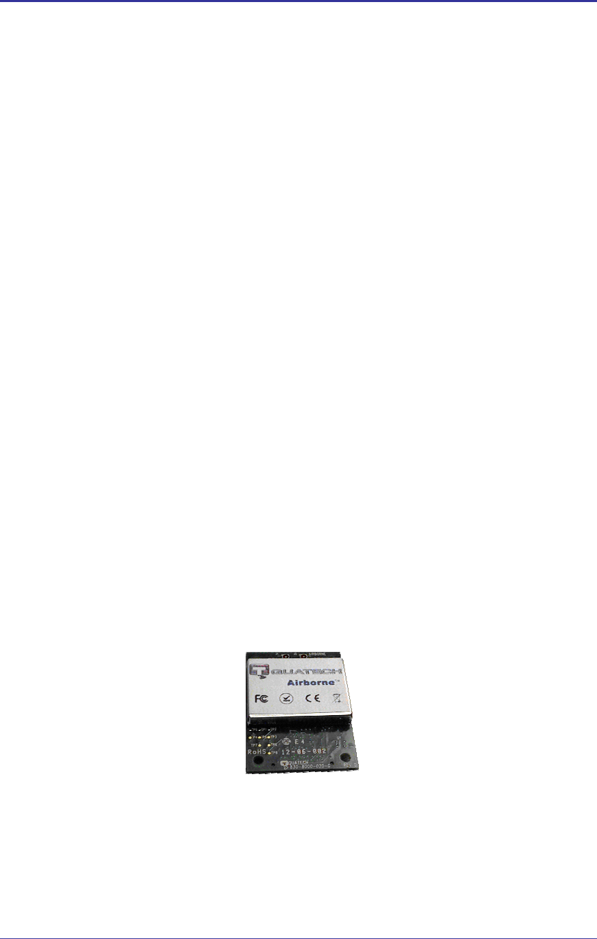
Figure 1- WLRG Radio
Company Confidential Quatech, Inc.
10 100-8026-100G Airborne 802.11b/g Value Radio Databook Revision 1.0
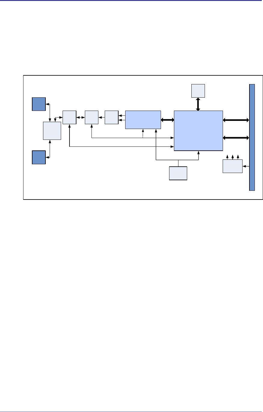
4.0 Block Diagrams
The following outlines the block diagram of the radio:
Figure 2 - Block Diagram for WLRG-RA-DP101
Marvell
Libertas 88W8385
IEEE 802.11 MAC & Baseband
Processor
CF Interface (50pin Hirose DF12)
Tx/Rx
Switch
Power
Management
Marvell
88W8015
RF Transceiver &
Integrated FEM
40 MHz
Xtal Oscillator
CEL SPDT
Antenna
Diversity
Switch
U.FL RF
Connector
U.FL RF
Connector
Host Interface (CF+)
Serial
EEPROM
1.2 VDC
1.8 VDC
2.8 VDC
Antenna select control
BALUN
Bandpass
Filter
Bluetooth
Coexistence

Quatech, Inc. Company Confidential
Revision 1.0 100-8026-100G Airborne 802.11b/g Value Radio Databook 11
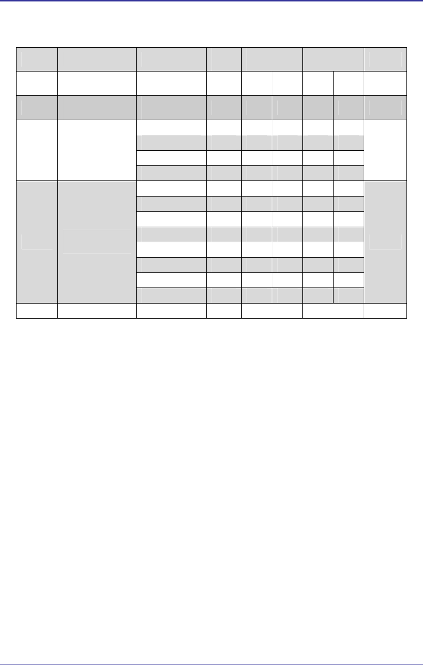
5.0 Model Numbers
The following table identifies the available model numbers for the radio family. Please
contact Quatech sales for details, quotes and availability.
Table 1 - Model Numbers
WiFi Interface Security
Model Number Description 11b/g PC16 WEP/WPA WPA2 RoHS
WLRG-RA-DP101 PC16 (CF+)
WLEG-RA-DP101
WLRG-RA-DP101 Evaluation Kit
WLRG-RA-DP1011 radio
PCMCIA Adapter Card
Tools/Documentation CD
Drivers (WinCE/WinXP/Linux)
Company Confidential Quatech, Inc.
12 100-8026-100G Airborne 802.11b/g Value Radio Databook Revision 1.0
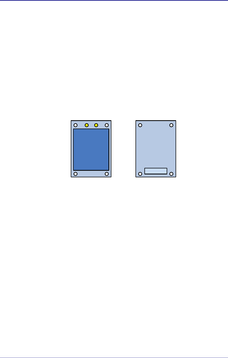
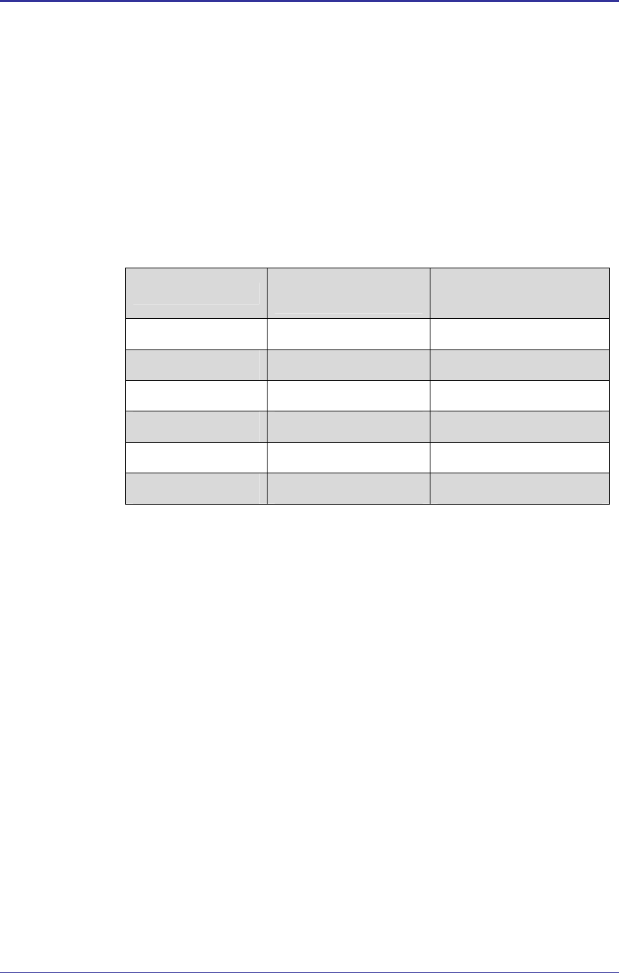
6.0 Pin out and Connectors
There are a total of three connectors to the radio:
J1: Digital Compact Flash interface to radio Baseband processor.
HRS DF12-50DS-0.5V (50pin Hirose)
J2, J3: RF connectors for antenna.
Hirose U.FL.
RF Shield
J2 J3
Top View Bottom
View
J1
Figure 3 – J1 - 50 pin Connector Layout (WLRG-RA-DP101) – Viewed from Bottom
Quatech, Inc. Company Confidential
Revision 1.0 100-8026-100G Airborne 802.11b/g Value Radio Databook 13
J1J1
1
2
49
50
Table 2 – WLRG-RA-DP101 (PC16) Pin Definition
Pin Signal Pin I/O Type Description
1 RF_VCC Power, 0.35A DC Power Supply 3.3V ±5%
2 RF_VCC Power, 0.35A DC Power Supply 3.3V ±5%
3 RF_VCC Power, 0.35A DC Power Supply 3.3V ±5%
4 RF_VCC Power, 0.35A DC Power Supply 3.3V ±5%
5 A00 5V tol, BiDir, 2mA, 50K Pull Down Host Address Input, Bits 0
6 D00 5V tol, BiDir, 2mA, 50K Pull Down Host Data Bus, Bits 0
7 A01 5V tol, BiDir, 2mA, 50K Pull Down Host Address Input, Bits 1
8 D01 5V tol, BiDir, 2mA, 50K Pull Down Host Data Bus, Bits 1
9 A02 5V tol, BiDir, 2mA, 50K Pull Down Host Address Input, Bits 2
10 D02 5V tol, BiDir, 2mA, 50K Pull Down Host Data Bus, Bits 2
11 A03 5V tol, BiDir, 2mA, 50K Pull Down Host Address Input, Bits 3
12 D03 5V tol, BiDir, 2mA, 50K Pull Down Host Data Bus, Bits 3
13 A04 5V tol, BiDir, 2mA, 50K Pull Down Host Address Input, Bits 4
14 D04 5V tol, BiDir, 2mA, 50K Pull Down Host Data Bus, Bits 4
15 A05 5V tol, BiDir, 2mA, 50K Pull Down Host Address Input, Bits 5
16 D05 5V tol, BiDir, 2mA, 50K Pull Down Host Data Bus, Bits 5
17 A06 5V tol, BiDir, 2mA, 50K Pull Down Host Address Input, Bits 6
18 D06 5V tol, BiDir, 2mA, 50K Pull Down Host Data Bus, Bits 6
19 A07 5V tol, BiDir, 2mA, 50K Pull Down Host Address Input, Bits 7
20 D07 5V tol, BiDir, 2mA, 50K Pull Down Host Data Bus, Bits 7
21 A08 5V tol, BiDir, 2mA, 50K Pull Down Host Address Input, Bits 8
22 GND Ground Digital Ground
23 A09 5V tol, BiDir, 2mA, 50K Pull Down Host Address Input, Bits 9
24 D08 5V tol, BiDir, 2mA, 50K Pull Down Host Data Bus, Bits 8
25 GND Ground Digital Ground
26 D09 5V tol, BiDir, 2mA, 50K Pull Down Host Data Bus, Bits 9
27 OE# 5V tol, BiDir, 2mA, 50K Pull Up Host Memory Attribute Space Output Enable

Company Confidential Quatech, Inc.
14 100-8026-100G Airborne 802.11b/g Value Radio Databook Revision 1.0
Pin Signal Pin I/O Type Description
28 D10 5V tol, BiDir, 2mA, 50K Pull Down Host Data Bus, Bits 10
29 WE# 5V tol, CMOS, Input, 50K Pull Up Host Memory Attribute Space Write Enable
30 D11 5V tol, BiDir, 2mA, 50K Pull Down Host Data Bus, Bits 11
31 IORD# 5V tol, BiDir, 2mA, 50K Pull Up Host I/O Space Read Strobe
32 D12 5V tol, BiDir, 2mA, 50K Pull Down Host Data Bus, Bits 12
33 IOWR# 5V tol, BiDir, 2mA, 50K Pull Up Host Space I/O Write Strobe
34 D13 5V tol, BiDir, 2mA, 50K Pull Down Host Data Bus, Bits 13
35 CE1# 5V tol, BiDir, 2mA, 50K Pull Up Host Select, Low Byte
36 D14 5V tol, BiDir, 2mA, 50K Pull Down Host Data Bus, Bits 14
37 CE2# 5V tol, BiDir, 2mA, 50K Pull Up Host Select, High Byte
38 D15 5V tol, BiDir, 2mA, 50K Pull Down Host Data Bus, Bits 15
39 GND Ground Digital Ground
40 GND Ground Digital Ground
41 RESET 5V tol, CMOS, ST (Schmitt Trigger)
Input, 50K Pull Up Hardware Reset
42 IREQ# 5V tol, BiDir, 2mA, 50K Pull Up Host interrupt Request (I/O Mode), also used as the
Module’s Ready (Memory Mode) output which is
asserted to indicate Module initialization is complete
43 REG# 5V tol, BiDir, 2mA, 50K Pull Up Host Attribute Space Select Memory mode: H for
common memory, L for attribute memory. The signal
must be low during I/O cycles when the I/O address is
on the bus.
44 WAIT# CMOS Output, 4mA, 10K Pull Up Host device must provide a 10K Pull Up
45 RF_LED# Input, 9mA LED cathode
46 IOIS16# Pull Low, Output 8 Bits or 16 Bits I/O Card selected
L: 16 bit or odd byte only operation
47 STSCHG# CMOS Output, 4mA 50K Pull Up Host Status Change
Shows the BVD1 (Battery Voltage Detect), BVD2, WP
(Write Protect), or Ready status changed.
48 CD1# Pull Low, Output Card Detect
49 GND Ground Digital Ground
50 INPACK# CMOS BiDir, 2mA, 50K Pull Up Host I/O Decode Confirmation. Asserted by the
Module when selected and responding to an I/O read
cycle. Used to control the HBA (Host Bus Adaptor) tri-
state buffer on/off).
Quatech, Inc. Company Confidential
Revision 1.0 100-8026-100G Airborne 802.11b/g Value Radio Databook 15
7.0 Electrical & RF Specification
Table 3- Absolute Maximum Values1
Parameter Min Max Unit
Supply Voltage Range 3.0 3.6 VDC
Supply Voltage -0.3 4.0 VDC
Operating Temperature Range -40 85 oC
Storage Temperature -55 125 oC
a These are absolute ratings; exceeding these values may cause
permanent damage to the device.
# All temperatures refer to ambient conditions.
Company Confidential Quatech, Inc.
16 100-8026-100G Airborne 802.11b/g Value Radio Databook Revision 1.0
Table 4 – Operating Conditions & DC Specification
Symbol Parameter Test Conditions Min Typ Max Units
VBUS Supply Voltage 3.135 3.3 3.465 V
ICCTXG Constant transmit current (802.11g) Transmitting @ 54Mb/s 475 485 mA
ICCRXG Constant receive current (802.11g) Receiving valid packets @
54MB/s 275 325 mA
ICCTXB Constant transmit current (802.11b) Transmitting @ 11Mb/s 450 500 mA
ICCRXB Constant receive current (802.11b)
Receiving valid packets @
11MB/s 275 325 mA
ISBIEEE IEEE Power Save Mode
Associated, Idle, Beacon
Interval = 100ms (DTIM=10) 8 20 mA
11Mbps, 8% PER 680 TDELAY Targeted Multipath Delay Spread
using IEEE 802.11 Naftali 54Mbps, 10% PER 150
ns
PER < 8% (11b mode) -10 RX_MAX IEEE Maximum Receive Level
PER < 10% (11g mode) -20
dBm
-90dBm Input -14 IIP3 3rd Order Intercept Point (Input)
-30dBm Input 4
dBm
IEEE 802.11g Carrier Leakage Per IEEE 802.11g 2 dB
TX_SUP IEEE 802.11b Carrier Suppression Per IEEE 802.11b 15 dB
PER < 8% (11b mode)1 36
PER < 10% (11g mode @
54Mbps) -1
ACR 802.11b/g Adjacent Channel
Rejection
PER < 10% (11g mode @
6Mbps) 16
dB
#
1. Adjacent channel measurement is carried out on two
channels separated by 25MHz (5 channels) for B/G-
modes.
2. Test Conditions: Supply Voltage (VCC) = 3.3VDC,
Ambient Temperature 258C, unless otherwise stated.
Quatech, Inc. Company Confidential
Revision 1.0 100-8026-100G Airborne 802.11b/g Value Radio Databook 17
Table 5 - PC16 (Compact Flash) Interface Specification
Symbol Parameter Min Typ Max Units
VIHPC16 Input HIGH Voltage VBUS=MAX, MIN 0.7 VBUS V
VILPC16 Input LOW voltage VBUS=MIN, MAX 0.3 VBUS V
VOHPC16 Output HIGH Voltage IOL = 2mA, VBUS=MIN 2.6 V
VOLPC16 Output LOW voltage IOL = 2mA, VBUS=MIN 0.05 V
ILPC16 Input Leakage Current VBUS=MAX,
Input = 0V or VCC -1 0.1 1 µA
CINPC16 Input Capacitance 5 10 pF
COUTPC16 Output Capacitance 5 10 pF
Table 6 - Supported Data Rates by Band
Band Supported Data Rates (Mbps)
802.11b 11, 5.5, 2, 1
802.11g 54, 48, 36, 24, 18, 12, 9, 6
Company Confidential Quatech, Inc.
18 100-8026-100G Airborne 802.11b/g Value Radio Databook Revision 1.0
Table 7 - Operating Channels
Band Region Freq Range
(GHz) No. of
Channels Channels
US/Canada 2.401 - 2.473 11 1 - 11
Europe 2.401 - 2.483 13 1 - 13
France 2.401 - 2.483 4 10 - 13
802.11b
Japan 2.401 - 2.495 14 1 - 14
US/Canada 2.401 - 2.473 11 1 - 11
Europe 2.401 - 2.483 13 1 - 13
France 2.446 - 2.483 4 10 - 13
802.11g
Japan 2.401 - 2.483 13 1 - 13
# 1. Only channels 1, 6 and 11 are non-overlapping.
Quatech, Inc. Company Confidential
Revision 1.0 100-8026-100G Airborne 802.11b/g Value Radio Databook 19
Table 8 - RF Characteristics – 802.11b/g
Symbol Parameter Rate (Mbps) Min
dBm Average
dBm / mW Peak
dBm / mW Units
POUTB Transmit Power
Output 802.11b 11, 5.5, 2, 1 13 15 31.6 19.3 85.1 dBm/mW
POUTG Transmit Power
Output 802.11g 6, 9,12,18, 24,
36, 48, 54 10 12 15.9 21.5 141.3 dBm/mW
11 -84
5.5 -85
2 -86
PRSENB Receive Sensitivity
802.11b
1 -86
dBm
54 -69
48 -70
36 -74
24 -78
18 -81
12 -83
9 -85
PRSENG Receive Sensitivity
802.11g
6 -86
dBm
FRANGEBG Frequency Range 2412 2484 MHz
Company Confidential Quatech, Inc.
20 100-8026-100G Airborne 802.11b/g Value Radio Databook Revision 1.0
7.1 AC Electrical Characteristics – Transmitter
Transmit power is automatically managed by the device for minimum power
consumption. The MAXIMUM transmit power at the RF connector is typically
+15dBm ± 2 dB for B-Mode (all rates) and +12dBm+/-2dB for G-Mode (all rates).
7.2 Performance/Range
The following table illustrates the typical data rates, performance and range the
device is capable of providing using an omni directional antenna.
Table 9 - Radio Typical Performance Range
Data Rate Typical Outdoor Distance
(Unity gain antenna)
Typical Outdoor Distance
(2dBi antenna gain on each end for B/G
mode)
1.0 Mb/s 240m 380m
11.0 Mb/s 135m 215m
6Mb/s 802.11g 135m 215m
6Mb/s 802.11a 49m 155m
54Mb/s 802.11g 12m 19m
54Mb/s 802.11a 4.5m 14m
Ranges are based on receiver sensitivity, Transmitter power, free-space path
loss estimates, antenna gain factors, and link margin estimates. Actual range will
vary from those stated. Non-line-of-site applications will result in typical values
less than shown above.
The Data Rate is the supported connection rate for the wireless link, the actual
data throughput for the link will be less than the stated data rates.

Quatech, Inc. Company Confidential
Revision 1.0 100-8026-100G Airborne 802.11b/g Value Radio Databook 21
8.0 Antenna
The unit supports antenna connection to two Hirose U.FL connectors, located on the top
surface of the radio next to the RF shielding. The radio supports Rx diversity.
Any antenna used with the system must be designed for operation within the 2.4GHz
ISM band and specifically must support the 2.412GHz to 2.482GHz for 802.11b/g
operation. They are required to have a VSWR of 2:1 maximum referenced to a 50ς
system impedance.
8.1 Antenna Selection
The Airborne radio supports a number of antenna options, all of which require
connection to the U.FL connectors on the radio. Ultimately the antenna option
selected will be determined by a number of factors, these include consideration
of the application, mechanical construction and desired performance. Since the
number of possible combinations is endless we will review some of the more
common solutions in this section. If your application is not covered during this
discussion please contact Technical Support for more specific answers.
The available antenna connections include:
Host board mounted antenna
Host Chassis mounted antenna
Embedded antenna
In addition to the above options, location and performance need to be
considered, the following sections discuss these items.
8.2 Host Board Mounted Antenna
Host board mounted requires that an antenna connection is physically mounted
to the host system board. It also requires that the host board include a U.FL
connector (two (2) if diversity is being used) to allow a U.FL to U.FL coaxial lead
to connect from the radio to the host board. It will then require 50ς matched PCB
traces to be routed from the U.FL connector to the antenna mount.
There are several sources for the U.FL to U.FL coaxial cable these include
Hirose, Sunridge and IPEX. Please contact Quatech for further part numbers and
supply assistance.
This approach can simplify assembly but does require that the host system
configuration can accommodate an antenna location that is determined by the
host PCB. There are also limitations on the ability to seal the enclosure when
using this approach.
This approach also restricts the selection of available antenna. When using this
approach antennas that screw or press fit to the PCB mount connector must be
used. There are many options for the antenna connector type, however if you
wish to utilize the FCC/IOC modular approval the connector choice must comply
with FCC regulations, these state a non-standard connector is required e.g.

Company Confidential Quatech, Inc.
22 100-8026-100G Airborne 802.11b/g Value Radio Databook Revision 1.0
TNC/SMA are not allowed (there are more that are not), RP-TNC/RP-SMA are
allowed.
8.3 Host Chassis Mounted Antenna
Host Chassis mounted antennas require no work on the host PCB. They utilize
an antenna type called ‘flying lead’. There are two types of flying leads; one
which provides a bulkhead mounted antenna connector and one which provides
a bulk head mounted antenna. The type you choose will be determined by the
application.
A flying lead system connects a U.FL coaxial lead to the radio’s U.FL connector,
the other end of the coax is attached to either a bulkhead mounted antenna
connector or directly to an antenna that has an integrated bulkhead mount.
In either of the two cases, the use of this approach significantly reduces the
antenna system development effort and provides for greater flexibility in the
available antenna types and placement in the host system chassis.
When using the flying lead antenna (integrated bulk head mounting), there are no
connector choice restrictions for use with the FCC/IOC modular certification.
However if the flying lead connector is used, the same restrictions as identified
for the Host Mounted Antenna apply.
There are many suppliers of flying lead antenna and connectors; Quatech’s
Airborne Antenna product line offers a range of antenna solutions.
8.4 Embedded Antenna
Use of Embedded antenna can be the most interesting approach for M2M,
industrial and medical applications. Their small form factor and absence of any
external mounting provides a very compelling argument for their use. There is a
downside to this antenna type and it comes with performance. Antenna
performance for all of the embedded options will, in most cases, be less that that
achievable with external antenna. This does not make them unusable; it will
impact choice of antenna type and requires more focus on placement.
The three main embedded antenna types are PCB embedded, chip (PCB
mounted) and flying lead; each has its advantages and disadvantages (See
Table 10).
Table 10 - Embedded Antenna Options
Features
Antenna Type Cost Size Availability Performance
PCB Embedded Lowest Largest Custom Poor
Chip Low Small Standard Poor
Flying Lead Low Small Standard Fair

Quatech, Inc. Company Confidential
Revision 1.0 100-8026-100G Airborne 802.11b/g Value Radio Databook 23
PCB Embedded – This approach embeds an antenna design into the host PCB.
This approach is very common with add-in WiFi card (CF, PCMCIA, SDIO, etc.)
as it requires no external connections and is the cheapest production approach.
The lower production cost requires significant development cost and lack of
performance and flexibility.
Chip – The integration of a chip antenna is simple and requires a relatively small
footprint on the host system, however, it does suffer from the same limitations of
flexibility and performance seen with the PCB embedded approach. There are
relatively large numbers of suppliers of this type of antenna; there is also a range
of configuration and performance options.
Flying Lead – This approach is similar to the flying lead solution for external
antennas, the difference is that the form factors are smaller and provide a range
of chassis and board mounting options, all for internal use. This approach suffers
less from the performance and flexibility limitations of the other approaches,
since the location of the antenna it not determined by the host PCB design. The
assembly of a system using this approach maybe slightly more complex since
the antenna is not necessarily mounted on the host PCBA.
8.5 Antenna Location
The importance of this design choice cannot be over stressed; it can in fact be
the determining factor between success and failure of the WiFi implementation.
There are several factors that need to be considered when determining location:
Distance of Antenna from radio
Location of host system
− Proximity to RF blocking or absorbing materials
− Proximity to potential noise or interference
− Position relative to infrastructure (Access Points or Laptops)
Orientation of host system relative to infrastructure
− Is it known
− Is it static
To minimize the impact of the factors above the following things need to be
considered during the development process:
Minimize the distance between the radio and the location of the antenna. The
coaxial cable between the two impacts the Transmit Power and Receive
Sensitivity negatively. Quatech recommends using 1.32-1.37mm outer
diameter U.FL coaxial cables.
Minimize the locations where metal surfaces come into contact or are close
to the location of the antenna.
Avoid locations where RF noise, close to or over lapping the ISM bands, may
occur. This would include microwave ovens and wireless telephone systems
in the 2.4GHz and 5.0GHz frequency range.
Try and mount the antenna as high on the equipment as possible.

Company Confidential Quatech, Inc.
24 100-8026-100G Airborne 802.11b/g Value Radio Databook Revision 1.0
Try to locate the antenna where there is a minimum of obstruction between
the antenna and the location of the Access Points. Typically Access Points
are located in the ceiling or high on walls.
Keep the main antenna’s polarization vertical, or in-line with the antenna of
the Access Points. 802.11 systems utilize vertical polarization and aligning
both transmit and receive antenna maximizes the link quality.
Utilize diversity where possible.
Utilize both spatial and polarization diversity where possible.
− Spatial diversity for the 2.4GHz band requires the antenna to be a
minimum 5” apart.
− Polarization diversity requires the antenna are not aligned, the angle
of separation should be determined by the possible range of
orientation of the host system.
Even addressing all of the above factors, does not guarantee a perfect
connection, however with experimentation an understanding of the best
combination will allow a preferred combination to be identified.
8.6 Performance
Performance is difficult to define as the appropriate metric changes with each
application or may indeed be a combination of parameters and application
requirements. The underlying characteristic that, in most cases, needs to be
observed is the link quality. This can be defined as the bandwidth available over
which communication, between the two devices, can be performed, the lower the
link quality the less likely the devices can communicate.
Measurement of link quality can be made in several ways; Bit Error rate (BER),
Signal to Noise (SNR) ratio, Signal Strength and may also include the addition of
distortion. The link quality is used by the radio to determine the link rate,
generally as the link quality for a given link rate drops below a predefined limit,
the radio will drop to the next lowest link rate and try to communicate using it.
The reciprocal is also true, if the radio observes good link quality at one rate it will
try to move up to the next rate to see if communication can be sustained using it.
It is important to note that for a given position the link quality improves as the link
rate is reduced. This is because as the link rate drops the radios Transmit power
and Receive sensitivity improve.
From this is can be seen the looking at the link rate is an indirect way of
assessing the quality of the link between the device and an Access Point. You
should strive to make the communication quality as good as possible in order to
support the best link rate. However be careful not to over specify the link rate.
Consider your applications bandwidth requirements and tailor your link rate to
optimize the link quality e.g. the link quality for a location at 6Mb/s is better than it
would be for 54Mb/s, if the application only needs 2Mb/s of data throughput, the
6Mb/s rate would provide a better link quality.
Aside from the radio performance, there are a number of other things that
contribute to the link quality; these include the items discussed earlier and
choices made when looking at the overall antenna gain. The antenna gain

Quatech, Inc. Company Confidential
Revision 1.0 100-8026-100G Airborne 802.11b/g Value Radio Databook 25
contributes to the Equivalent Isotropically Radiated Power (EIRP) of the system.
This is part of an overall measurement of the link quality called link margin.
Link Margin provides a measure of all the parts of the RF path that impact the
ability of two systems to communicate. The basic equation looks like this:
EIRP (dB) = TxP + TxA – TxC
Link Margin (dB) = EIRP – FPL + (RxS + RxA – RxC)
Where: TxP = Transmitter output power (dBm)
TxA = Transmitter antenna gain (dBi)
TxC = Transmitter to Antenna coax cable loss (dB)
FPL = Free Path Loss (dB)
RxS = Receiver receive sensitivity (dBm)
RxA = Receiver antenna gain (dBi)
RxC = Receiver to Antenna coax cable loss (dB)
This is a complex subject and requires more information that is presented here,
Quatech does recommend at least looking at the subject and evaluating any
system at a basic level.
It is then possible, with a combination of the above items and an understanding
of the application demands, to achieve a link quality optimized for the application
and host design. It is important to note that this is established with a combination
of hardware selection, design choices and configuration of the radio.
Company Confidential Quatech, Inc.
26 100-8026-100G Airborne 802.11b/g Value Radio Databook Revision 1.0
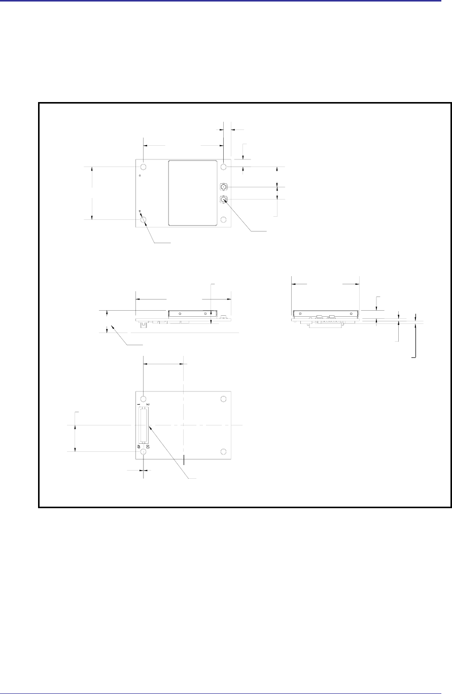
9.0 Mechanical Outline
Figure 4 - WLRG-RA-DP101 Family Mechanical Outline
Typical module profile off host PCB
7.48 [0.29]
16 [0.63]
DIMENSIONS: mm [inches]
TOLERANCE: ± 0.127mm
PN: HRS DF12-50DS-0.5V(86)
U.FL-R-SMT
HRS COAXIAL ANTENNA
CONECTOR, 2 PLACES
0.10 [0.004]
10.50 [0.41]
3 [0.12]
32 [1.26]
4X Ø2.20 [Ø0.09]
21 [0.83]
7.95 [0.31]
3 [0.1]
5 [0.2]
1.11 [0.04]
0.97 [0.04]
1.81 [0.07]
27 [1.06]
38 [1.50]
5.33 [0.21]

Quatech, Inc. Company Confidential
Revision 1.0 100-8026-100G Airborne 802.11b/g Value Radio Databook 27
10.0 Drivers and Software
Quatech supports its radios with a collection of drivers and tools. Driver supports OS’s
which include WinXP, WinCE and Linux 2.6. These drivers are supplied with the radio in
the development kit or can be obtained directly from Quatech Technical Support.
A range of engineering tools are also available to assist in the integration of the radio into
a system, evaluation of the radio for application suitability and regulatory testing. Please
contact Quatech Sales or Technical Support for more information and availability of these
tools.

Company Confidential Quatech, Inc.
28 100-8026-100G Airborne 802.11b/g Value Radio Databook Revision 1.0
11.0 Integration Guidelines
The Airborne Performance Radio is designed for integration in to a wide range of
advanced electronic systems and diverse applications, the success of the integration and
final performance of the integrated system depends upon the integration process and
hardware design, the following section provides a set of guidelines to optimize the
integration of the radio.
The following guidelines address hardware design requirements for the integration of the
radio under normal conditions, should your application not be able to support the listed
guidelines please contact Quatech.
11.1 General Requirements
3.3VDC65% on all VDD pins
Digital Ground on all VSS pins
Mechanical mounting method other than J1
11.2 Power Supply Guidelines
3.3VDC65%
500mA constant current
3000mA start-up current for 35ms
150mV ripple voltage (f<50Hz) at constant receive current
11.3 EMI/EMF Guidelines
To minimize electromagnetic interference (EMI) and radio frequency interference
(RFI), pay strict attention to power and signal routing near the Radio. As much as
possible, the keep-clear area below the Radio should be a solid copper ground
plane. It is anticipated that the Radio will be mounted on a board with a
committed ground plane. Ensure the PCB interconnect has a designed
impedance of 50-75 Ohms.
To keep signal impedance as low as possible, connect the ground plane to
internal ground planes by several vias. Ground signals to the Radio connector
should connect directly to the ground plane below the Radio. Individual ground
connections to the Radio should have a solid ground connection, preferably
directly to the ground plane on the same surface side where the Radio resides.
Do not connect ground pins directly to an inside layer ground plane using vias
only.
Keep interconnects from the Radio connector as short as possible on the
mounting layer. All inboard signals–including pin numbers–must immediately
transition to a different routing layer using a via as close to the connector as
possible. Outboard signals (odd pin numbers) should also be kept to a minimum
length.
Quatech, Inc. Company Confidential
Revision 1.0 100-8026-100G Airborne 802.11b/g Value Radio Databook 29
11.4 Circuit Board Layout Guidelines
When considering capacitance, calculations must consider all device loads and
capacitances due to printed circuit board traces. Capacitance due to the traces
depend on a number of factors, including the trace width, dielectric material from
which the circuit board is made, and proximity to ground and power planes.
The mating connector required on the host board is a DF12(4.0)-50DP-0.5, the
manufacturer is Hirose.
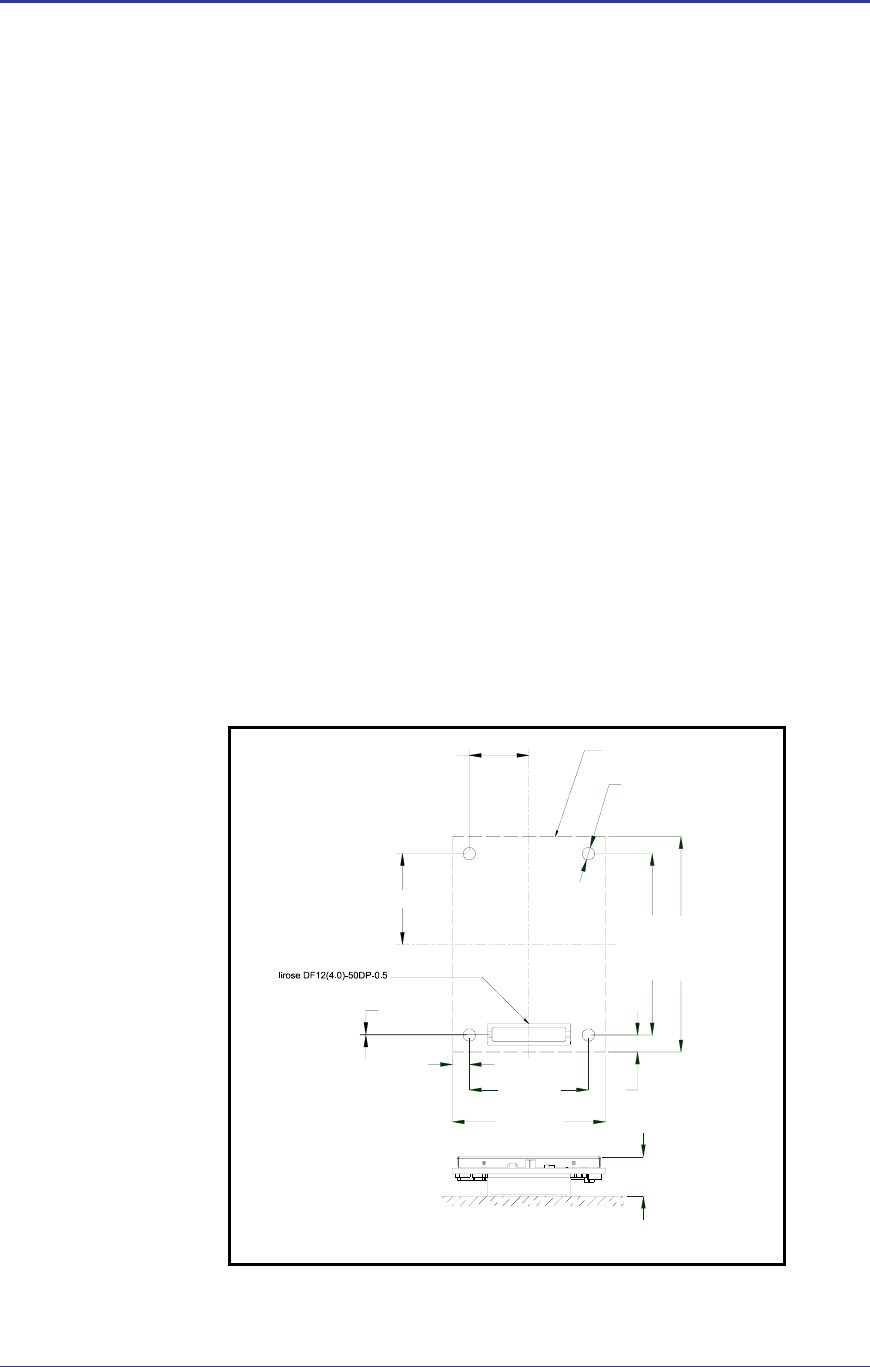
11.5 Mounting Guidelines
Special care must be observed when placing the Module. In particular:
The antenna must not be mounted beneath any other printed circuit boards,
components, or metallic housing.
The proximity of the antenna to large metallic objects can affect the range
and performance of the Module.
Packaging and enclosure designers must carefully review the placement of
the Module in the enclosure to minimize interference or blocking sources.
For mechanical clearance, performance, and emissions reasons, there should be
no components placed on the main printed circuit board facing the Module. This
area should be clear of any components. The recommended mounting footprint
for the radios can be seen in Figure 5.
Figure 5 - WLRG-RA-DP101 Mounting Footprint
Radio PCB Outline
0.630 [16.00]
0.413 [10.50]
0.004 [0.10]
Dimensions: inches [mm]
PC16 (CF) Header
1
250
49
.827 [21.00]
.118 [3.00]
1.063 [27.00]
Ø.086 [Ø2.18]
1.260 [32.00]
.118 [3.00]
1.496 [38.00]
.295 [7.48]
Company Confidential Quatech, Inc.
30 100-8026-100G Airborne 802.11b/g Value Radio Databook Revision 1.0
11.6 RESET Timer Guidelines
Figure 6 - RESET Pulse Timing
T
RESET
RESET
Table 11 - RESET Timing
Symbol Parameter Min Typ Max Units
TRESET RESET minimum pulse
width VCC=MAX, MIN 101 100 ns
# 1. This is the minimum value guaranteed for a valid
RESET. Smaller values may trigger the reset circuit.

Quatech, Inc. Company Confidential
Revision 1.0 100-8026-100G Airborne 802.11b/g Value Radio Databook 31
12.0 Certification & Regulatory Approvals
The unit complies with the following agency approvals:
Table 12 - Regulatory Approvals
Country Standard Status
North America
(US & Canada)
FCC Part 15
Sec. 15.107, 15.109, 15.207, 15.209, 15.247
Modular Approval
Granted
Europe
CISPR 16-1 :1993
ETSI EN 300 328 Part 1 V1.2.2 (2000-07)
ETSI EN 300 328 Part 2 V1.1.1 (2000-07)
Completed
Japan
ARIB STD-T71 v1.0, 14 (Dec 2000)
ARIB RCR STD-T33 (June 19, 1997)
ARIB STD-T66 v2.0 (March 28, 2002)
Pending
12.1 FCC Statement
This equipment has been tested and found to comply with the limits for a Class B
digital device, pursuant to Part 15 of the FCC Rules. These limits are designed
to provide reasonable protection against harmful interference in a residential
installation. This equipment generates uses and can radiate radio frequency
energy and if not installed and used in accordance with the instructions, may
cause harmful interference to radio communications. However, there is no
guarantee that interference will not occur in a particular installation. If this
equipment does cause harmful interference to radio or television reception, which
can be determined by turning the equipment off and on, the user is encouraged
to try to correct the interference by one or more of the following measures:
Reorient or relocate the receiving antenna.
Increase the separation between the equipment and receiver.
Connect the equipment to an outlet on a circuit different from that to which
the receiver is connected.
Consult the dealer or an experienced radio/TV technician for assistance.
Operation is subject to the following two conditions: (1) this device may not cause
interference, and (2) this device must accept any interference, including
interference that may cause undesired operation of the device.
12.2 FCC RF Exposure Statement
To satisfy RF exposure requirements, this device and its antenna must operate
with a separation distance of a least 20 cm from all persons and must not be co-
located or operating in conjunction with any other antenna or transmitter.
Company Confidential Quatech, Inc.
32 100-8026-100G Airborne 802.11b/g Value Radio Databook Revision 1.0
12.3 Information for Canadian Users (IC Notice)
This device has been designed to operate with an antenna having a maximum
gain of 5dBi for 802.11b/g band. An antenna having a higher gain is strictly
prohibited per regulations of Industry Canada. The required antenna impedance
is 50 ohms.
To reduce potential radio interference to other users, the antenna type and its
gain should be so chosen that the equivalent isotropically radiated power (EIRP)
is not more than required for successful communication.
Operation is subject to the following two conditions: (1) this device may not cause
interference, and (2) this device must accept any interference, including
interference that may cause undesired operation of the device.
12.4 FCC/IOC Modular Approval
This document describes the Airborne WLN FCC modular approval and the
guidelines for use as outlined in FCC Public Notice (DA-00-1407A1).
The WLRG-RA-DP101 is covered by the following modular grants:
Country Standard Grant
North America
(US)
FCC Part 15
Sec. 15.107, 15.109, 15.207, 15.209, 15.247
Modular Approval
F4AWLNG1
Canada RSS 210
Modular Approval 39139A-WLNG1
By providing FCC modular approval on the Airborne WLN modules, the
customers are relieved of any need to perform FCC part15 subpart C Intentional
Radiator testing and certification, except where they wish to use an antenna that
is not already certified.
Quatech supports a group of pre-approved antenna; use of one of these
antennas eliminates the need to do any further subpart C testing or certification.
If an antenna is not on the list, it is a simple process to add it to the pre-approved
list without having to complete a full set of emissions testing. Please contact
Quatech Technical support for details of our qualification processes.
Please note that as part of the FCC requirements for the use of the modular
approval, the installation of any antenna must require a professional installer.
This is to prevent any non-authorized antenna being used with the radio. There
are ways to support this requirement but the most popular is to utilize a non-
standard antenna connector, this designation includes the reverse polarity
versions of the most popular RF antenna types (SMA, TNC, etc.). For more
details please contact Quatech.
The user is advised that changes or modifications not expressly approved by the
party responsible for FCC compliance could void the user's authority to operate
the equipment.

Quatech, Inc. Company Confidential
Revision 1.0 100-8026-100G Airborne 802.11b/g Value Radio Databook 33
Antennas approved for use with this grant are:
Nearson S141AH-2450S
WiMo 17010.1
Nearson S151M2-L-2450S
Nearson S181TR-2450S
Nearson S151M2-L-2450S
Antenex TRA24003P
Laird MAF 94045
The following documents are associated with this applications note:
FCC Part 15 – Radio Frequency Devices
FCC Public Notice – DA-00-1407A1 (June 26th, 2000)
Quatech recommends that during the integration of the radio, into the customers
system, that the referenced design guidelines, outlined in section 11.0 of this
manual, be followed. Please contact Quatech Technical Support if you have any
concerns regarding the hardware integration.
Contact Quatech Technical support for a copy of the FCC and IOC grant
certificates, the test reports and updated approved antenna list.
Company Confidential Quatech, Inc.
34 100-8026-100G Airborne 802.11b/g Value Radio Databook Revision 1.0
13.0 Physical & Environmental Approvals (Preliminary)
The device has passed the following primary physical and environmental tests. The test
methods referenced are defined in SAE J1455 Aug1994.
Table 13 - Mechanical Approvals
Test Reference Conditions
Temperature Range
(Operational) -40°C to +85°C
Temperature Range (Non-
Operational) -50°C to +125°C
Humidity Sect 4.2 0-95%RH @ 38°C condensing
Salt Spray Sect 4.3 5%NaCl @ 35°C, 1000hrs
Altitude Sect 4.8
Operational: 0-15,000ft (+6.4 PSIA Internal
Non-operational: 0-40,000ft (+12 PSIA Internal)
Vibration Sect 4.9 Operational: 2.4 Grms, 10-1K Hz, 1hr per axis
Non-operational: 5.2 Grms, 10-1K Hz, 1hr per axis
Shock Sect 4.10 Operational: 20Gs MAX, 11ms half-sine pulse
Product Drop Sect 4.10.3.1 1m onto concrete, any face or corner, 1 drop
Packaging Drop Sect 4.10.2.1 32 inches onto concrete on each face and corner.
Packaged in ‘for transit’ configuration.

Quatech, Inc. Company Confidential
Revision 1.0 100-8026-100G Airborne 802.11b/g Value Radio Databook 35
14.0 Glossary
Term Description
802.11 Wireless standards developed by the IEEE that specify an "over-the-air" interface for wireless Local Area
Networks. 802.11 is composed of several standards operating in different radio frequencies.
802.11a 802.11a is an IEEE specification for wireless networking that operates in the 5 GHz frequency range
(5.150 GHz to 5.825 GHz) with a maximum 54 Mbps data transfer rate. The 5 GHz frequency band is not
as crowded as the 2.4 GHz frequency, because the 802.11a specification offers more radio channels
than the 802.11b/g. These additional channels can help avoid radio and microwave interference.
802.11b 802.11b is the international standard for wireless networking that operates in the 2.4 GHz frequency
range (2.4 GHz to 2.4835 GHz) and provides a throughput of up to 11 Mbps.
802.11g 802.11g is similar to 802.11b, but this standard provides a throughput of up to 54 Mbps. It also operates
in the 2.4 GHz frequency band but uses OFDM radio technology in order to boost overall bandwidth.
Access Point An interface between a wireless network and a wired network Access Points can combine with a
distribution system such as Ethernet to create multiple radio cells (BSSs) that enable roaming throughout
a facility.
Ad-Hoc mode A wireless network composed of only stations and no Access Point. Also referred to as “peer-to-peer”
networks
Association service An IEEE 802.11 service that an enables the mapping of a wireless station to the distribution system via
an Access Point.
Asynchronous transmission Type of synchronization where there is no defined time relationship between transmission of frames.
Authentication The process a station uses to announce its identify to another station. IEEE 802.11 specifies two forms
of authentication: open system and shared key.
Bandwidth The amount of transmission capacity available on a network at any point in time. Available bandwidth
depends on several variables such as the rate of data transmission speed between networked devices,
network overhead, number of users, and the type of device used to connect PCs to a network.
Basic Service Set (BSS) A set of 802.11-compliant stations that operate as a connected wireless network.
Bits per second (bps) A measurement of data transmission speed over communication lines based on the number of bits that
can be sent or received per second.
BSSID Basic Service Set Identifier. A 48-bit identifier used by all stations in a BSS in frame headers. Usually
MAC address.
Clear channel assessment A function that determines the state of the wireless medium in an IEEE 802.11 network.
Client Any computer connected to a network that requests services (files, print capability) from another member
of the network.
Command Line Interface (CLI) A method of interacting with the Airborne WLN Module by sending it typed commands.
Direct sequence spread spectrum
(DSSS) Combines a data signal at the sending station with a higher data rate bit sequence, which many refer to
as a chip sequence (also known as processing gain). A high processing gain increases the signal’s
resistance to interference. The minimum processing gain that the FCC allows is 10, and most products
operate under 20.
Disassociation service An IEEE 802.11 term that defines the process a station or Access Point uses to notify that it is
terminating an existing association.
Distribution service An IEEE 802.11 station uses the distribution service to send MAC frames across a distribution system.
GPIO General Purpose Input/Output refers to the digital I/O lines.
Host application The environment within which the Module is embedded - typically includes a processor, which forms part
of an OEM’s product and application.
Hot spot Same as an Access Point, usually found in public areas such as coffee shops and airports.
IEEE Institute of Electrical and Electronic Engineers, an international organization that develops standards for
electrical . The organization uses a series of numbers, like the Dewey Decimal system in libraries, to
differentiate between the various technology families.

Company Confidential Quatech, Inc.
36 100-8026-100G Airborne 802.11b/g Value Radio Databook Revision 1.0
Term Description
Independent Basic Service Set
Network (IBSS Network) An IEEE 802.11-based wireless network that has no backbone infrastructure and consists of at least two
wireless stations. This type of network is often referred to as an Ad-Hoc network because it can be
constructed quickly without too much planning.
Infrastructure mode A client setting providing connectivity to an Access Point. As compared to Ad-Hoc mode, whereby PCs
communicate directly with each other, clients set in Infrastructure mode all pass data through a central
Access Point. The Access Point not only mediates wireless network traffic in the immediate
neighborhood, but also provides communication with the wired network. See Ad-Hoc and AP.
LAN application A software application that runs on a computer, which is attached to a LAN, Intranet or the Internet, and
using various protocols can communicate with the Module.
Local Area Network A system of connecting PCs and other devices within the same physical proximity for sharing resources
such as Internet connections, printers, files and drives. When Wi-Fi is used to connect the devices, the
system is known as a wireless LAN or WLAN.
Medium Access Control Layer One of two sub-layers that make up the Data Link Layer of the OSI reference model. The MAC layer is
responsible for moving data packets to and from one network node to another across a shared channel.
MPDU MAC Protocol Data Unit, the unit of data exchanged between two peer MAC entities using the services
of the physical layer (PHY).
MSDU MAC Service Data Unit, information that is delivered as a unit between MAC service Access Points
(SAPs).
Peer-to-peer network A wireless or wired computer network that has no server or central hub or router. All the networked PCs
are equally able to act as a network server or client, and each client computer can talk to all the other
wireless computers without having to go through an Access Point or hub. However, since there is no
central base station to monitor traffic or provide Internet access, the various signals can collide with each
other, reducing overall performance. Also referred to as “ad-hoc” networks
RS-232 An EIA standard that specifies up to 20 Kbps, 50 foot, serial transmission between computers and
peripheral devices.
RSSI Relative Signal Strength Indicator or Receive Signal Strength Indicator, is a measure of the received
signal strength against the maximum internal receive signal strength (determined during the radios test
and calibration). Usually displayed as a percentage.
RTOS An operating system implementing components and services that explicitly offer deterministic responses,
and therefore allow the creation of real-time systems. An RTOS is characterized by the richness of the
services it provides, the performance characteristics of those services, and the degree that those
performance characteristics can be controlled by the application engineer ( to satisfy the requirements of
the application).
Service Set Identifier (SSID) An identifier attached to packets sent over the wireless LAN that functions as a "name" for joining a
particular radio network (BSS). All radios and Access Points within the same BSS must use the same
SSID, or their packets will be ignored.
Secure Digital Input Output (SDIO) Standards based high speed serial interface, maintained by the SD Card Association (www.sdcard.org).
Telnet A virtual terminal protocol used in the Internet, enabling users to log into a remote host.
Transceiver A device for transmitting and receiving packets between the computer and the medium.
Transmission Control Protocol
(TCP) A commonly used protocol for establishing and maintaining communications between applications on
different computers. TCP provides full-duplex, acknowledged, and flow-controlled service to upper-layer
protocols and applications.
Wide Area Network (WAN) A communication system of connected PCs and other computing devices across a large local, regional,
national or international geographic area. Also used to distinguish between phone-based data networks
and Wi-Fi. Phone networks are considered WANs and Wi-Fi networks are considered wireless LANs.
Wi-Fi Wireless-Fidelity: Wi-Fi is the common name used for 802.11 wireless network technology.
Wi-Fi Alliance A non-profit international association formed in 1999 to certify interoperability of wireless LAN products
based on IEEE 802.11 specification.
Wired Equivalent Privacy (WEP) A security protocol for wireless LANs defined in the IEEE 802.11 standard. WEP is designed to provide
the same level of security as a wired LAN.

Quatech, Inc. Company Confidential
Revision 1.0 100-8026-100G Airborne 802.11b/g Value Radio Databook 37
Term Description
WLAN Also referred to as a wireless LAN. A type of local-area network that uses high-frequency radio waves
rather than wires to communicate between nodes and provide network connectivity.

Company Confidential Quatech, Inc.
38 100-8026-100G Airborne 802.11b/g Value Radio Databook Revision 1.0
15.0 Change Log
The following table indicates all changes made to this document:
Version Date Section Change Description Author
1.0 12/1/2007 - Preliminary Release ACR

QUATECH ® Inc..
5675 Hudson Industrial Parkway
Hudson, OH 44236
USA
Telephone: 330-655-9000
Toll Free: 800-553-1170
Fax: 330-655-9010
Technical Support: 714-899-7543 / wirelesssupport@quatech.com
Web Site: www.quatech.com
Copyright © 2007 QUATECH ® Inc.
ALL RIGHTS RESERVED. No part of this publication may be copied in any form, by photocopy, microfilm, retrieval
system, or by any other means now known or hereafter invented without the prior written permission of QUATECH ® Inc..
This document may not be used as the basis for manufacture or sale of any items without the prior written consent of
QUATECH Inc..
QUATECH Inc. is a registered trademark of QUATECH Inc..
Airborne™ is a trademark of QUATECH Inc..