BARCO AMM215WTTP LCD Color Display User Manual
Advan Int'l Corp. LCD Color Display Users Manual
UserManual.wiki
>
BARCO
>
AMM215WTTP User Manual
Users Manual
Navigation menu
Upload a User Manual
Namespaces
Wiki Guide
HTML
PDF
Info
Views
User Manual
Discussion / Help
Navigation
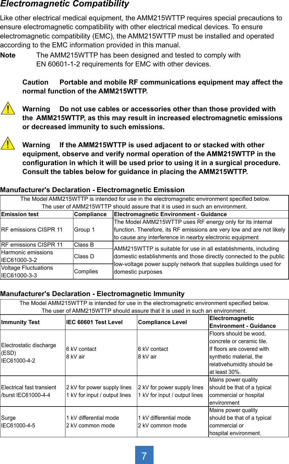
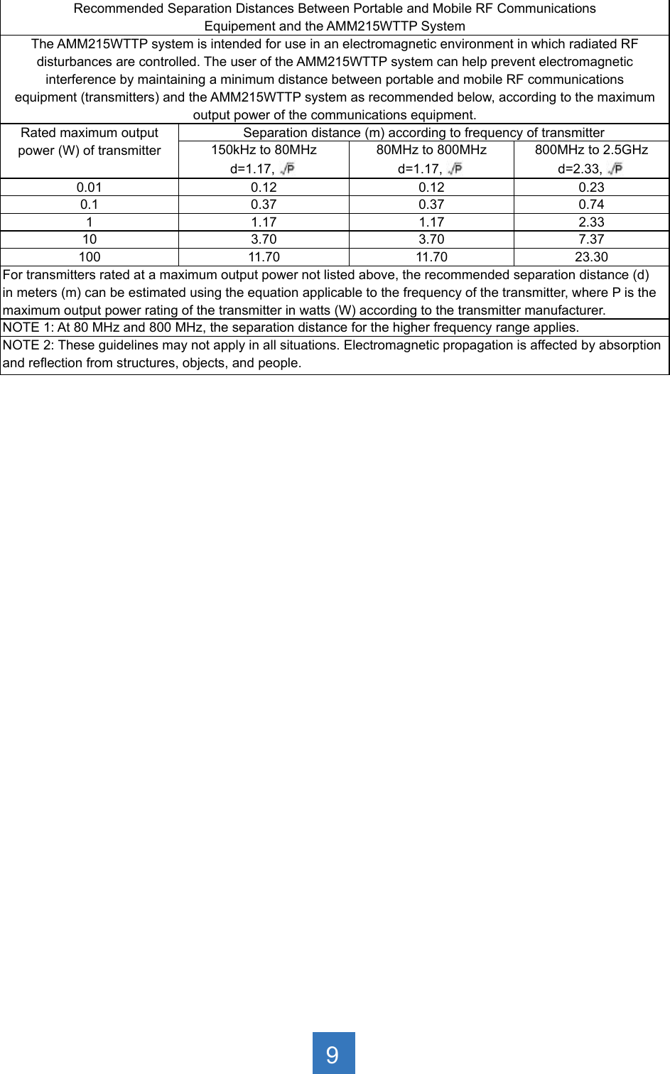
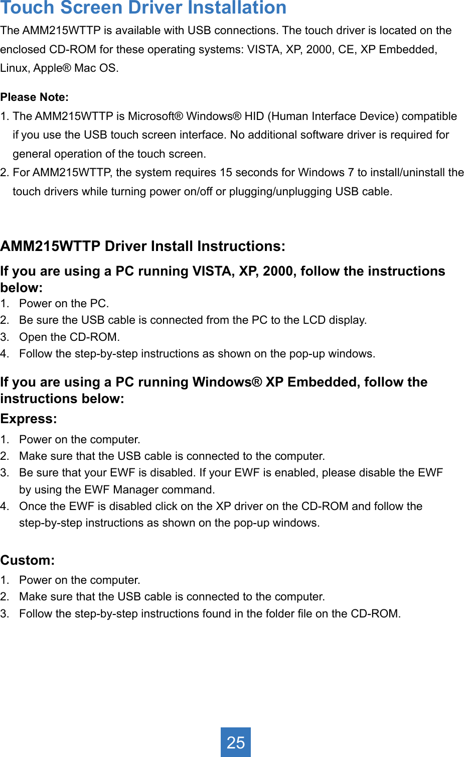
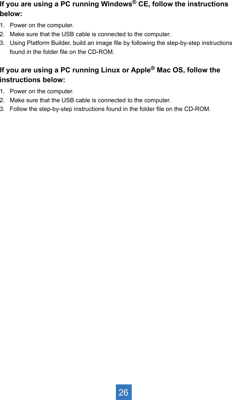
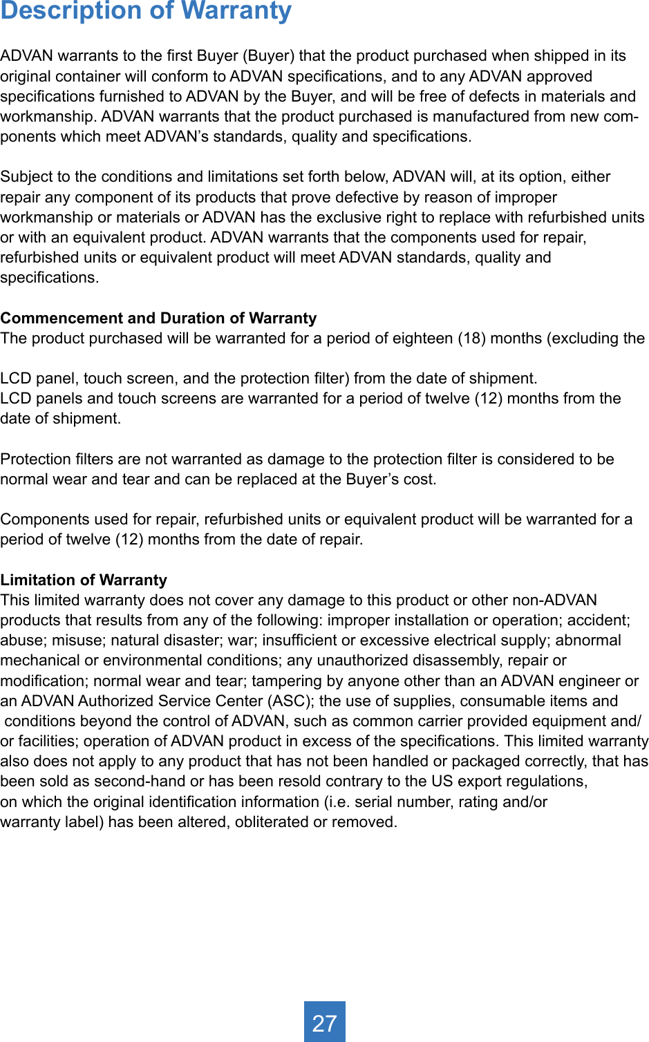
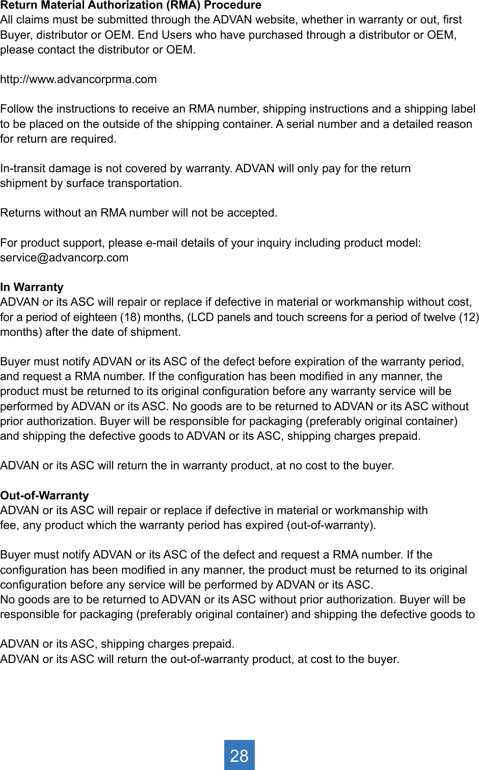
![Power frequency(50/60Hz) mag-netic eldIEC 61000-4-83.0 A/m 3.0 A/mPower frequency magnetic elds should be at levels characteristic of a typical location in a typical commercial orhospital environment. Voltage dips, short interruptions andvoltage variations onpower supply inputlines IEC61000-4-11<5% Ut (>95% dip in Ut)for 0.5 cycle 40% Ut (60% dip in Ut)for 5 cycles 70% Ut (30% dip in Ut)for 25 cycles <5% Ut (>95% dip in Ut)for 5 sec. <5% Ut (>95% dip in Ut)for 0.5 cycle 40% Ut (60% dip in Ut)for 5 cycles 70% Ut (30% dip in Ut)for 25 cycles <5% Ut (>95% dip in Ut)for 5 sec. Mains power quailityshould be that of a typicalcommercial or hospitalenvironment. If the user of the AMM215WTTP image intensier requirescontinued operation during power mains interruptions, it is commended that the AMM215WTTP image intensier bepowered from an uninterruptible power supply or a battery.Note: Ut is the A.C. mains voltage prior to application of the test level.Manufacturer's Declaration - Electromagnetic ImmunitThe Model AMM215WTTP is intended for use in the electromagnetic environment specied below. The customer or the user of AMM215WTTP should ensure that it is used in such an environment. Immunity Test IEC 60601 Test Level Compliance Level Electromagnetic Environment - Guidance Conducted RFIEC61000-4-6Radiated RFIEC 61000-4-33 Vrms 150 KHz to 80 MHz 3 Vrms 800 MHz to 2.5 GHz 3 Vrms 150 KHz to 80 MHz 3 Vrms 800 MHz to 2.5 GHz Portable and mobile RF communications equipment should be used no closer toany part of the AMM215WTTP, includingcables, than the recommended separationdistance calculated from the equationapplicable to the frequency of thetransmitter.Recommended Separation Distance0.15 MHz to 80 MHz 80 MHz to 800 MHz800 Mhz to 2.5GHzwhere P is the maximum output power rating of the transmitter in watts (W)according to the transmitter manufacturer and is the recommended separation distance in meters (m). Field strengths from xed RF transmitters,as determined by an electromagneticsite survey (a), should be less than the compliance level in each frequency range(b).Interferency may occur in the vicinity of equipment marked with the following symbol:NOTE 1: At 80MHz and 800MHz, the higher frequency range applies. NOTE 2: These guidelines may not apply in all situations. Electromagnetic propagation is affected by absorption and reection from structures, objects, and people. (a) Field strengths from xed transmitters, such as base stations for radio (cellular/cordless) telephones and land mobile radios, amateur radio, AM and FM radio broadcast and TV broadcast, connot be predicted theoretically with accuracy. To assess the electromagnetic environment due to xed RF transmitters, an electromagnetic site survey should be considered. If the measured eld strength in the location in which the AMM215WTTP is used exceeds the applicable RF compliance level above, the AMM215WTTP should be observed to verify normal operation. If abnormal performance is observed, additional measures may be necessary, such as reorienting or relocating the AMM215WTTP. (b) Over the frequency range 150kHz to 80MHz, eld strengths should be less than [V1] V/m. 8](https://usermanual.wiki/BARCO/AMM215WTTP/User-Guide-2645943-Page-11.png)