BARCO AMM215WTTP LCD Color Display User Manual
Advan Int'l Corp. LCD Color Display Users Manual
BARCO >
Users Manual

Rev.B
AMM215WTTP
LCD Color Display
USER’s GUIDE
Rev.A
Table of Contents
Warnings and Cautions 1
Warnings ..................................................................................................................... 2
Cautions ...................................................................................................................... 3
Symbol Definitions ....................................................................................................... 4
Usage Notice 9
Precautions ................................................................................................................. 9
Introduction 10
About AMM215WTTP Series ......................................................................................10
Touch Screen for AMM215WTTP ...............................................................................10
Package Overview .....................................................................................................11
Installation 13
Product Overview .......................................................................................................13
Front View ..............................................................................................................13
Bottom View (Without Stand) .................................................................................13
VESA Mount for Your Monitor .....................................................................................14
Start Your Installation .................................................................................................15
Connecting the Display ...............................................................................................16
Figure .....................................................................................................................17
User Controls 18
Side Panel Controls ....................................................................................................18
How to Use the OSD Menus .......................................................................................19
On-Screen Display Menus ..........................................................................................20
Appendix 21
Troubleshooting ..........................................................................................................21
Warning Signal ...........................................................................................................22
No Signal ................................................................................................................22
Going to Sleep............................................................................................................22
Out of Range ..........................................................................................................22
Product Dimensions ...................................................................................................23
Compatibility Modes ...................................................................................................24
Touch Screen Driver Installation .................................................................................25
AMM215WTTP Driver Install Instructions ................................................................25
Description of Warranty 27
The information contained in this document is subject to change without notice.
This document contains proprietary information that is protected by copyright. All rights
are reserved. No part of this document may be reproduced,translated to another language
or stored in a retrieval system, or transmitted by any means, electronic, mechanical,
photocopying, recording, or otherwise, without prior written permission. Windows is a registered
trademark of Microsoft, Inc. Other brand or product names are trademarks of their respective
holders.
Caution!
Any changes or modications not expressly approved by the party responsible for
compliance could void the user’s authority to operate the equipment.

Warnings and Cautions
Please read this manual and follow its instructions carefully. The words warning, caution, and
note carry special meanings and should be carefully reviewed:
Warning The personal safety of the patient or physician may be involved.
Disregarding this information could result in injury to the patient or
physician.
Caution Special service procedures or precautions must be followed to avoid
damaging the instrument.
Note Special information to make maintenance easier or important information
more clear.
A lightning bolt within a triangle is intended to warn of the presence of
hazardous voltage. Refer all service to authorized personnel.
Warranty is void if any of these warnings are disregarded.
ADVAN Int’l Corp accepts full responsibility for the effects on safety, reliability, and
performance of the equipment only if:
‧Re-adjustments, modications, and/or repairs are carried out exclusively by ADVAN Int’l
Corp.
‧The electrical installation of the relevant operating room complies with the applicable IEC
and CE requirements.
Warning Federal law (United States of America) restricts this device to use by,
or on order of a physician.
ADVAN Int’l Corp's AMM215WTTP monitor has been tested under ANSI/AAMI ES60601-1
standard for Medical application.
ADVAN Int’l Corp reserves the right to make improvements in the product(s) described
herein. Product(s), therefore, may not agree in detail to the published design or
specications. All specications are subject to change without notice.
Please use rear cover page with ADVAN contact points or phone your local ADVAN Int’l Corp
sales representative or agent for information on changes and new products.
1

Warnings
Warning TO AVOID POTENTIAL SERIOUS INJURY TO THE USER AND THE
PATIENT AND/OR DAMAGE TO THIS DEVICE, THE USER MUST :
1. Read the operating manual thoroughly and be familiar with its contents prior to using this
equipment.
2. Carefully unpack the unit and check if any damage occurred during shipment.
3. Should any solid object or liquid fall into the panel, unplug the unit and have it checked
by qualied personnel before operating it any further.
4. Uplug the unit if it is not to be used for an extended period of time. To disconnect the
cord, pull it out by the plug. Never pull the cord itself.
5. Be a qualied physician, having complete knowledge of the use of this equipment.
6. Test this equipment prior to a medical procedure. This monitor was fully tested at the
factory before shipment.
7. Avoid removing covers on control unit to avoid electric shock.
8. Attempt no internal repairs or adjustments not specically detailed in this operating
manual.
9. Pay close attention to the care, cleaning instructions in this manual. A deviation may
cause damage (refer to the Cleaning section).
10. DO NOT STERILIZE MONITOR.
11. Read the entire instruction manual before assembling or connecting the camera.
12. Do not place the monitor or any other heavy object on the power cord. Damage to the
cable can cause re or electirc shock.
13. Monitor with power supply is suitable for use in patient environment.
14. DO NOT stack more than "6" boxes high.
15. To avoid risk of electric shock, this equipment must only be connected to supply mains
with protective earth.
16. Do not modify this equipment without authorization of the manufacturer.
17. Power cord is used as a disconnection device. To de-energize equipment, disconnect the
power cord. ME Equipment should be placed easily powered off place.
This equipment has been tested and found to comply with the limits for medical devices in
IEC 60601-1-2. These limits are designed to provide reasonable protection against harmful
interference in a typical medical installation.
NOTICES TO USER
This device complies with Part 15 of the FCC Rules. Operation is subject to the following two
conditions:
(1) this device may not cause harmful interference, and (2) this device must accept any
interference received, including interference that may cause undesired operation.
2

Cautions
1. The AC Adapter must be plugged into a grounded power outlet.
2. Use only the proprietary AMM215WTTP power supply for the AMM215WTTP monitor.
3. Turn power off when unit is not in use. Disconnect the power plug from AC outlet if the
product is not going to be used for an extended period of time.
4. Never operate the unit right after having transported from a cold location directly to a
warm location.
5. Do not expose the monitor to moisture or directly apply liquid cleaners directly to the
screen. Spray the cleaning solution into a soft cloth and clean gently.
6. Handle the monitor with care. Do not strike or scratch the screen.
7. Do not block the monitor cooling vents. The monitor is cooled by natural convection and
has no fan.
8. Do not force the monitor past 28 degrees of vertical when adjusting the screen position.
(For monitors equipped with stands only.)
9. Remove the power module and connection when transporting the unit.
10. Save the original carton and associated packing material. They will be useful should you
have to transport or ship the unit.
11. Allow adequate air circulation to prevent internal heat buildup.
12. Do not place the unit on surfaces (rugs, blankets, etc.) or near materials (curtains,
draperies) that may block the ventilation slots.
13. Do not install the unit near sunlight, excessive dust, mechanical vibration or shock.
14. The unit is designed for operation in a horizontal position. Never operate the unit in a
vertical position.
15. Keep the unit away from equipment with strong magnets (i.e. a large loudspeaker.)
16. Equipment with SIP/SOP connectors should either comply with IEC 60601-1 and/or
IEC 60601-1-1 harmonized national standard or the combination should be evaluated.
Do not touch the patient with signal input or output connectors.
17. Use only a hospital grade power supply cord.
18. This equipment has been tested and found to comply with the limit for a Class B digital
device, pursuant to Part 15 of the FCC Rules. These limits are designed to provide
reasonable generate uses and can radiate radio frequency energy, if not installed
and used in accordance with the instructions, may cause harmful interference to radio
communications. However, there is no guarantee that interference will not occur in
a particular installation, which can be detemined by turning the equipment off and on, the
user is encourage to try to correct the interference by one or more of the following
measures:
‧
Reorient or relocate the receiving device.
‧
Increase the separation distance between the equipment.
‧
Connect the equipment to an outlet on a circuit different from that to which the
other device(s) are connected.
‧
Consult the manufacturer or eld service technican for help.
19. Grounding reliability can only be achieved when the equipment is connected to an
equipment receptacle labeled “Hospital Only” or “Hospital Grade.”
Caution To connect to an international power supply, use a an attachment plug
appropriate for the power outlet.
Caution Refer to the “Electromagnetic Compatibility” (EMC) section of this manual
to ensure EMC. The AMM215WTTP must be installed and operated
according to the EMC information provided in this manual.
3
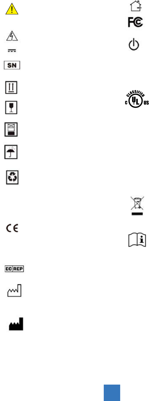
For indoor use only.
Tested to comply with FCC
Class B standards.
DC power control switch
Medical Equipment
With respect to electric shock,
re and mechanical hazards
only in accordance with
ANSI/
AAMI ES60601-1(2005/(R)2012
+ A1:2012, C1:2009/(R)2012 +
A2:2010/(R)2012), and CSA-C22.2
NO. 60601-1:14 Edition 3 -
Revision Date 2014.01.01
Tested to comply with IP
IPX1 (ingression protection) Rating
WEEE symbol for the
recyclable product. Please do
not throw the product with this
symbol in the bin.
Consult instructions for use
Symbol Denitions
General warning sign
of risk of danger
Dangerous: High Voltage
Direct Current
Serial Number
This way up
Fragile, handle with care
6 Stacking limit by number
Keep dry
Recyclable
Indicates proof of conformity
to applicable European
"Economic Community Council"
directives and to harmonized
standards published in the
ofcial journal of the European
Communities.
Authorized Representative in
Europe
Date of Manufacture
Manufacturer
51LJ
E472062
4

EU Declaration of Conformity for Medical Applications
A Declaration of Conformity has been led for this product. A sample of this document may
be found in the addendum which accompanied this manual. For a copy of the Declaration
of Conformity document, please contact ADVAN Int’l Corp. and request for AMM215WTTP
DOC.
Cleaning Your Monitor
Turn off the product before cleaning. No specic liquid or chemical is necessary when
cleaning this LCD monitor. However, it is suggested to use a soft cloth moistened with mild
detergent to clean the display housing.
To clean the screen, do not spray liquid cleaners directly on to the unit. Spray cleaning
solution onto a cloth, and without applying excessive pressure, clean the screen.
Caution: Do not use abrasive cleaners, waxes or solvents for your cleaning.
5

This monitor is intended for use in Health Care Facilities Model AMM215WTTP Equipment is
not suitable for use in the presence of ammable anesthetic mixture with air or with oxygen
or nitrous oxide.
No user serviceable parts inside, ask qualied personnel when accessing inside.
This product contains electrical waste or electronic equipment. It must not be disposed of as
unsorted municipal waste and must be collected separately.
Electrical input rating: 12V DC 3A
Classication
Type of protection against electric shock: Class I Equipment.
Degree of protection against the ingress of water: IPX1 compliance.
Mode of operation: Continuous
This monitor has been tested to comply with IEC/EN 60601-1, IEC/EN60601-1-2 and is
certied by UL to medical standard(UL/cUL Mark).
Because many medical ofces are located in residential areas, this monitor, in addition to the
medical requirements, has also been tested and found to comply with
the limits for FCC Class B computing devices in a typically congured system. It is the
system integrator or congurer’s responsibility to test and ensure that the entire
system complies with applicable EMC laws.
Environmental conditions for transport and storage:
- Temperature range within -4° to 140° F (-20° to 60°C)
- Relative humidity range within 10% to 90%
- Atmospheric pressure range within 500 to 1060 hPa.
- Operating within 0° to 40°C
Environmental conditions for operating:
- Operating temperature range within 32° to 104° F (0° to 40°C)
6
Electromagnetic Compatibility
Like other electrical medical equipment, the AMM215WTTP requires special precautions to
ensure electromagnetic compatibility with other electrical medical devices. To ensure
electromagnetic compatibility (EMC), the AMM215WTTP must be installed and operated
according to the EMC information provided in this manual.
Note The AMM215WTTP has been designed and tested to comply with
EN 60601-1-2 requirements for EMC with other devices.
Caution Portable and mobile RF communications equipment may affect the
normal function of the AMM215WTTP.
Warning Do not use cables or accessories other than those provided with
the AMM215WTTP, as this may result in increased electromagnetic emissions
or decreased immunity to such emissions.
Warning If the AMM215WTTP is used adjacent to or stacked with other
equipment, observe and verify normal operation of the AMM215WTTP in the
conguration in which it will be used prior to using it in a surgical procedure.
Consult the tables below for guidance in placing the AMM215WTTP.
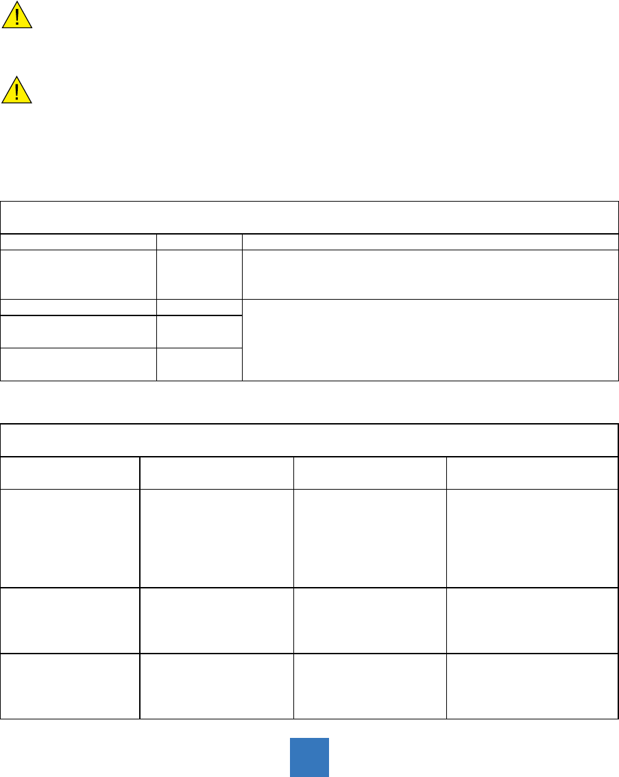
Manufacturer's Declaration - Electromagnetic Emission
The Model AMM215WTTP is intended for use in the electromagnetic environment specied below.
The user of AMM215WTTP should assure that it is used in such an environment.
Emission test Compliance Electromagnetic Environment - Guidance
RF emissions CISPR 11 Group 1
The Model AMM215WTTP uses RF energy only for its internal
function. Therefore, its RF emissions are very low and are not likely
to cause any interference in nearby electronic equipment
RF emissions CISPR 11 Class B AMM215WTTP is suitable for use in all establishments, including
domestic establishments and those directly connected to the public
low-voltage power supply network that supplies buildings used for
domestic purposes
Harmonic emissions
IEC61000-3-2 Class D
Voltage Fluctuations
IEC61000-3-3 Complies
Manufacturer's Declaration - Electromagnetic Immunity
The Model AMM215WTTP is intended for use in the electromagnetic environment specied below.
The user of AMM215WTTP should assure that it is used in such an environment.
Immunity Test IEC 60601 Test Level Compliance Level Electromagnetic
Environment - Guidance
Electrostatic discharge
(ESD)
IEC61000-4-2
6 kV contact
8 kV air
6 kV contact
8 kV air
Floors should be wood,
concrete or ceramic tile.
If oors are covered with
synthetic material, the
relativehumidity should be
at least 30%.
Electrical fast transient
/burst IEC61000-4-4
2 kV for power supply lines
1 kV for input / output lines
2 kV for power supply lines
1 kV for input / output lines
Mains power quality
should be that of a typical
commercial or hospital
environment
Surge
IEC61000-4-5
1 kV differential mode
2 kV common mode
1 kV differential mode
2 kV common mode
Mains power quality
should be that of a typical
commercial or
hospital environment.
7
Power frequency
(50/60Hz) mag-netic eld
IEC 61000-4-8
3.0 A/m 3.0 A/m
Power frequency magnetic
elds should be at levels
characteristic of a typical
location in a typical
commercial orhospital
environment.
Voltage dips, short
interruptions andvoltage
variations onpower supply
inputlines IEC61000-4-11
<5% Ut (>95% dip in Ut)
for 0.5 cycle
40% Ut (60% dip in Ut)for
5 cycles
70% Ut (30% dip in Ut)for
25 cycles
<5% Ut (>95% dip in Ut)
for 5 sec.
<5% Ut (>95% dip in Ut)
for 0.5 cycle
40% Ut (60% dip in Ut)
for 5 cycles
70% Ut (30% dip in Ut)
for 25 cycles
<5% Ut (>95% dip in Ut)
for 5 sec.
Mains power quailityshould
be that of a typicalcommercial
or hospitalenvironment. If the
user of the AMM215WTTP
image intensier
requirescontinued operation
during power mains
interruptions, it is commended
that the AMM215WTTP image
intensier bepowered from an
uninterruptible power supply
or a battery.
Note: Ut is the A.C. mains voltage prior to application of the test level.
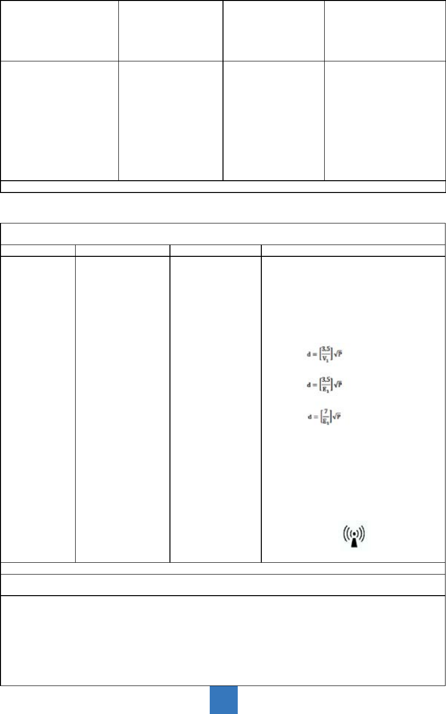
Manufacturer's Declaration - Electromagnetic Immunit
The Model AMM215WTTP is intended for use in the electromagnetic environment specied below. The customer
or the user of AMM215WTTP should ensure that it is used in such an environment.
Immunity Test IEC 60601 Test Level Compliance Level Electromagnetic Environment - Guidance
Conducted RF
IEC61000-4-6
Radiated RF
IEC 61000-4-3
3 Vrms
150 KHz to 80 MHz
3 Vrms
800 MHz to 2.5 GHz
3 Vrms
150 KHz to 80 MHz
3 Vrms
800 MHz to 2.5 GHz
Portable and mobile RF communications
equipment should be used no closer toany
part of the AMM215WTTP, includingcables,
than the recommended separationdistance
calculated from the equationapplicable to the
frequency of thetransmitter.
Recommended Separation Distance0.15 MHz
to 80 MHz
80 MHz to 800 MHz
800 Mhz to 2.5GHz
where P is the maximum output power
rating of the transmitter in watts (W)
according to the transmitter manufacturer
and is the recommended separation
distance in meters (m). Field strengths from
xed RF transmitters,as determined by an
electromagneticsite survey (a), should be less
than the compliance level in each frequency
range(b).Interferency may occur in the vicinity
of equipment marked with the following
symbol:
NOTE 1: At 80MHz and 800MHz, the higher frequency range applies.
NOTE 2: These guidelines may not apply in all situations. Electromagnetic propagation is affected by absorption
and reection from structures, objects, and people.
(a) Field strengths from xed transmitters, such as base stations for radio (cellular/cordless) telephones and land
mobile radios, amateur radio, AM and FM radio broadcast and TV broadcast, connot be predicted theoretically
with accuracy. To assess the electromagnetic environment due to xed RF transmitters, an electromagnetic site
survey should be considered. If the measured eld strength in the location in which the AMM215WTTP is used
exceeds the applicable RF compliance level above, the AMM215WTTP should be observed to verify normal
operation. If abnormal performance is observed, additional measures may be necessary, such as reorienting or
relocating the AMM215WTTP.
(b) Over the frequency range 150kHz to 80MHz, eld strengths should be less than [V1] V/m.
8

Recommended Separation Distances Between Portable and Mobile RF Communications
Equipement and the AMM215WTTP System
The AMM215WTTP system is intended for use in an electromagnetic environment in which radiated RF
disturbances are controlled. The user of the AMM215WTTP system can help prevent electromagnetic
interference by maintaining a minimum distance between portable and mobile RF communications
equipment (transmitters) and the AMM215WTTP system as recommended below, according to the maximum
output power of the communications equipment.
Rated maximum output
power (W) of transmitter
Separation distance (m) according to frequency of transmitter
150kHz to 80MHz
d=1.17,
80MHz to 800MHz
d=1.17,
800MHz to 2.5GHz
d=2.33,
0.01 0.12 0.12 0.23
0.1 0.37 0.37 0.74
1 1.17 1.17 2.33
10 3.70 3.70 7.37
100 11.70 11.70 23.30
For transmitters rated at a maximum output power not listed above, the recommended separation distance (d)
in meters (m) can be estimated using the equation applicable to the frequency of the transmitter, where P is the
maximum output power rating of the transmitter in watts (W) according to the transmitter manufacturer.
NOTE 1: At 80 MHz and 800 MHz, the separation distance for the higher frequency range applies.
NOTE 2: These guidelines may not apply in all situations. Electromagnetic propagation is affected by absorption
and reection from structures, objects, and people.
9

Introduction
About AMM215WTTP Series
The AMM215WTTP Touch screen LCD Monitor displays information from imaging systems and
devices.
Features include:
• Direct Analog signal input
• Direct Digital signal input
• Active matrix TFT LCD technology
• 1920 x 1080 resolution
• 21.5" viewable display area - 16:9 aspect ratio
• 31.47 ~ 82.3 KHz horizontal scan
• 56 ~ 75 Hz high refresh rate
• 0.24795mm x 0.24795mm pixel pitch
• Auto adjustment function
• Multilingual OSD user control
• 100 mm VESA mount
• Removable base for exible mounting solutions.
• Touch screen with USB controller
• Audio output(optional)
• USB HUB 2.0(optional)
Touch Screen for AMM215WTTP
• Projected Capacitive touch screen for nger input only
• Surface: Glare treatment
• Interface: USB controller
• Transmittance: 90%±5%
• HID: Windows® 7
• Driver: VISTA, XP, 2000, CE, XP Embedded, Linux, Apple® Mac OS
10

11
Package Overview
*Accessories might change depending on region.
LCD Display Power Cord VGA Signal Cable
USB Cable ( A to B) DVI-D Cable
Quick Start Guide Touch Driver CD
DC Power Supply
Audio Cable
(optional)

Unpacking the Monitor
Before you unpack your monitor, prepare a suitable workspace. You need a stable and level
surface near a grounded wall outlet in an area which is relatively free of glare from sunlight
or other sources of bright light. The monitor is cooled by natural convection (it has no fan).
For optimum performance, do not block the cooling vents.
While unpacking the monitor, inspect it and other package contents for shipping damage that
could cause a re or shock hazard. Immediately report any shipping damage to the carrier or
transportation company or contact customer service for returns.
After you unpack the monitor, make sure the following items are included:
‧
Monitor with video cable
‧
AC adapter with cable
CAUTION: AC Adapter must be plugged into grounded a power outlet
CAUTION : AC adapter
Manufacturer: BridgePower Corp.
Model No: BPM050S12F09
INPUT: 100-240Vac, 50-60 Hz, 1.5A
OUTPUT: 12Vdc, 4.2A
‧
This operations manual
Note: Your system provider may offer alternative cords or cables depending on
the installation requirement and local geography issues.
12
Installation
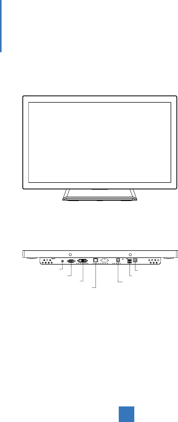
Product Overview
• Front View
• Bottom View (Without Stand)
VGA
DVI
USB B-Type
DC IN
RJ11
USB A-Type
AUDIO
13
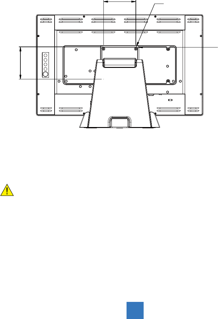
Flat Panel Mounting Physical Mounting Interface by
VESA
This monitor conforms to the VESA Flat Panel Mounting Physical Mounting Interface
standard which denes a physical mounting interface for at panel monitors, and
corresponding with the standards of at panel monitor mounting devices, such as wall and
table arms. The VESA mounting interface is located on the back of your monitor.
To mount the monitor on a UL certied swing arm or other mounting xture, follow the
instructions included with the mounting xture to be used.
Warning
Please select the proper screws!
The distance between the back cover surface and the bottom of the screw hole is 8
mm. Please use four M4 screws diameter with proper length to mount your monitor.
Please note: the mounting stand must be able to support at least 17.6 lbs (8Kg).
14
100.0 mm
100.0 mm
Slots(X6)
VESA
Mounting
Interface

Start Your Installation
Please follow these instructions so that you can hook up the cables to associated connectors.
1. Lay the LCD at on an even surface.
2. Move the stand into position as seen in the step 1 diagram.
3. Connect the cables to the appropriate connectors as seen in the step 2 diagram.
15
Step 2
VGA USB
DVI DC IN
Step 2
Step 1

16
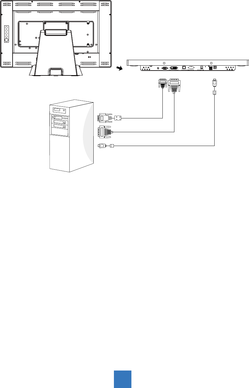
Connecting the Display
To setup this display, please refer to the following gure and procedures.
1. Be sure all equipment is turned off.
2. Connect the DC plug to the power connector on the monitor and the other end into an
electrical outlet (8.1).
3. Connect the D-SUB or DVI cable from the display’s D-SUB or DVI input connector to the
D-SUB or DVI connector of your host computer and tighten the screws (8.1).
4. Connect the USB cable from the USB port of your display to the USB port (8.1) of your
computer.
5. Congure the touch screen. Refer to the “Touch Screen Driver Installation” section on
page 16.
6. Once the touch screen is congured, the monitor is ready for use.
Note:
Avoid placing the monitor against a bright background or where sunlight or other light
sources may reect on the area of the monitor. Place the monitor just below eye level.
To ensure the LCD display works well with your computer, please congure the display mode
of your graphics card to make it less than or equal to 1920 x 1080 resolution and make sure
the timing of the display mode is compatible with the LCD display.
We have listed the compatible “Video Modes” of your LCD display in the appendix
(on page 24) for your reference.
External power supplies applicable: Bridgepower / BPM050S12F09
Recommendation to Use more than One Unit
As unforeseen situations can occasionally occur with the monitor, when the display is used
please use a safety control. It is strongly recommended the user uses more than one unit or
prepares a spare unit in case there is an emergency.
On Burn-in
Permanent burn-in may occur from the followings:
‧ Displaying color bar or static images repeatedly or for a long period of time.
‧ Using the unit repeatedly in a high temperature/ high humidity environment
‧ Displaying an image smaller than the monitor continuously.
17
Figure
18
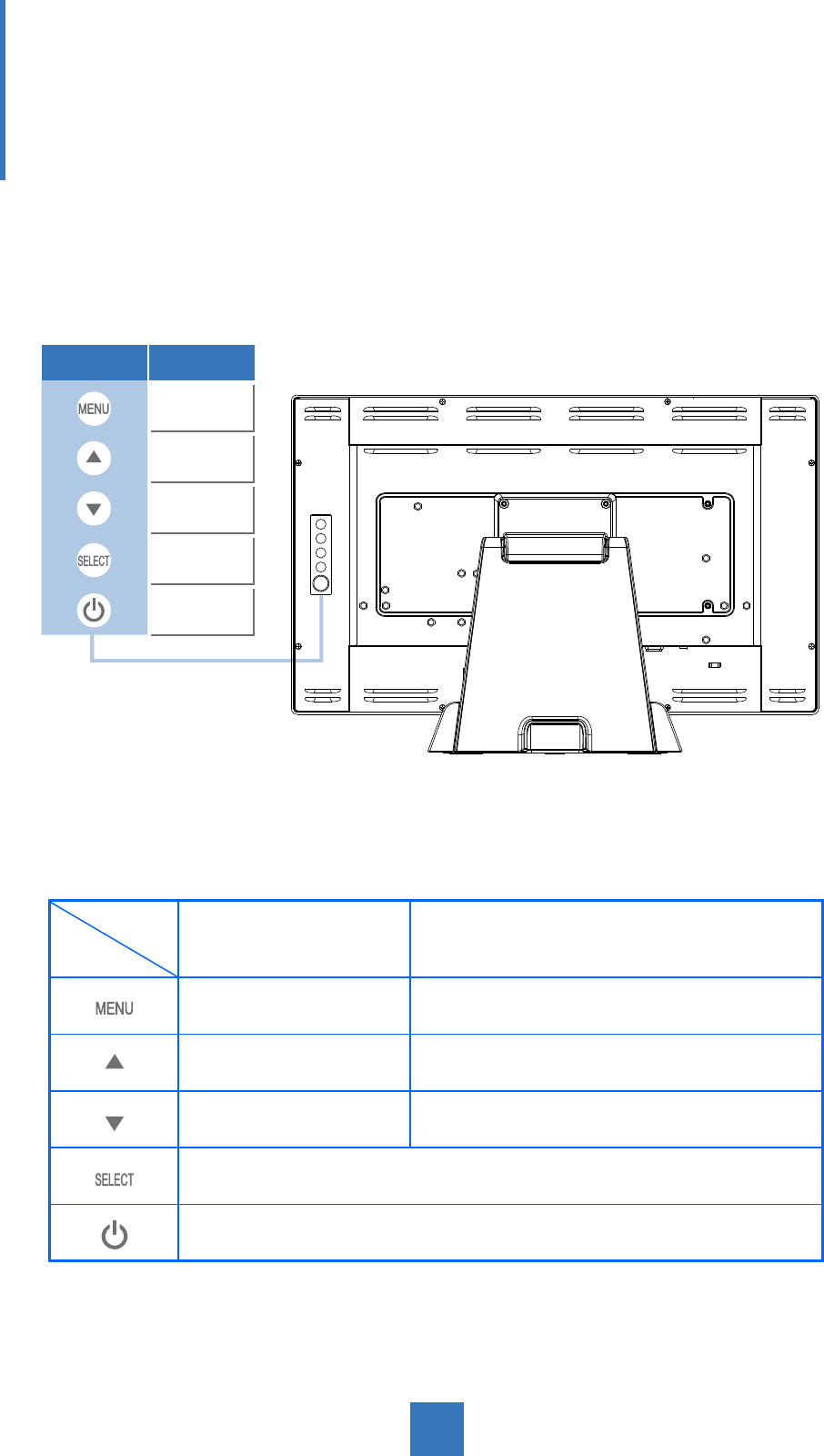
User Controls
Back Panel Controls
OSD
Key Menu off status Menu on status
Menu appear Menu disappear / return to main item
Brightness Main item select up / Adjust up
Mute Main item select down / Adjust down
Select sub-item function
Power On / Off
Icon Key Name
Menu
Up
Down
Select
Power

19
How to Use the OSD Menus
Icon Key Name
Menu
Up
Down
Select
Power
1. Press the “Menu” button to pop up the “on-screen menu” and press “Up” or “Down”
button to select among the ve functions in the main menu.
2. Choose the adjustment items by pressing the “Select” button.
3. Adjust the value of the adjustment items by pressing the “Up” or “Down” button.
4. With the OSD menu on the screen, press the “Menu” button to return to the main menu
or to exit OSD.
5. The OSD menu will automatically close, if you have left it idle for a pre-set time.
6. To Lock the OSD / Power menu buttons, please follow the instructions below.
(Please note: the monitor has to be turned ON with a valid signal pre-set)
(a.) Press the “Menu” key; the OSD menu will open.
(b.) Press and hold the “Menu” key again with the OSD menu on the screen; the OSD
menu will disappear. Then press the “Power” key 1 time while the menu key is still
being pressed. The “Lock/Unlock” menu will appear for 3 seconds.
(c.) Use the “Select” key to select OSD or Power setting then set at “Lock” by pushing the
“UP” or “Down” button.
(d.) When the “UP” or “Down” button is released, the previous setting will be saved and
exit the “Lock/Unlock” menu automatically.
7. To Unlock the OSD / Power menu buttons, please follow the instructions below.
(Please note: the monitor has to be turned ON with a valid signal pre-set)
(a.) Press and hold the “Menu” key then press the “Power” key simultaneously; the
“Lock/Unlock” menu will appear for 3 seconds.
(b.) Use the “Select” key to select OSD or Power setting then set at “Unlock” by pushing
the “UP” or “Down” button.
(c.) When the “Up” or “Down” button is released, the previous setting will be saved, and
the “Lock/Unlock” menu will close automatically.
Please note:
a. When the OSD Lock function is selected, this indicates that all the buttons except
the “power” button are now disabled.
b. When the Power Lock function is selected, the “Power” key is disabled. The user
cannot turn off the monitor with the “Power” key.

20
On-Screen Display Menus
Main OSD Menu:
ITEM CONTENT
Contrast The monitor luminance level control.
Brightness The monitor backlight level control.
Auto Adjust Fine-tune the image to full screen automatically.
Left/Right Moving screen image horizontal position to left or right.
Up/Down Moving screen image vertical position to up or down.
Horizontal size The screen image horizontal dot clock adjustment.
Fine The screen image pixel phase adjustment.
OSD Left/Right Moving OSD menu horizontal position to left or right.
OSD Up/Down Moving OSD menu vertical position to up or down.
OSD Time out OSD auto-disappear time selection.
OSD Language OSD menu language selection. ( English, French, Japanese, Deutsch,
Spanish, Italian, Traditional Chinese and Simplied Chinese)
Factory Reset Factory default value restored.
RGB Color temperature selection. (9300K, 6500K, 5500K, 7500K, User)
Volume Audio volume adjustment
Mute Audio ON/OFF control

21
Appendix
Troubleshooting
If you are experiencing trouble with the LCD display, refer to the following. If the problem
persists, please contact your local dealer or our service center.
Problem: No image appears on screen.
► Check that all the I/O and power connectors are correctly and well connected
as described in the “Installation” section.
► Make sure the pins of the connectors are not crooked or broken.
Problem: Partial Image or incorrectly displayed image.
► Check to see if the resolution of your computer is higher than that of the LCD
display.
► Recongure the resolution of your computer to make it less than or equal to
1920 x 1080.
Problem: Image has vertical ickering line bars.
► Use “Horizontal size” to make an adjustment.
► Check and recongure the display mode of the vertical refresh rate of your
graphic card to make it compatible with the LCD display.
Problem: Image is unstable and ickering
► Use “Fine” to make an adjustment.
Problem: Image is scrolling
► Check and make sure the VGA signal cable (or adapter) is securely connected.
► Check and recongure the display mode of the vertical refresh rate of your
graphics card to make it compatible with the LCD display.
Problem: Vague image (characters and graphics)
► Use “Horizontal size” to make an adjustment. If this problem still exists, use “Fine”
to make an adjustment.

Warning Signal
If you see warning messages on your LCD screen, this means that the LCD display cannot
receive a clean signal from the computer graphics card.
Below are the three kinds of Warning Signal. Please check the cable connections or contact
your local dealer or our service center for more information.
No Signal
This message means that the LCD display has been powered on but it cannot receive any
signal from the computer graphics card. Check all the power switches, power cables, and
VGA/DVI signal cable.
Going to Sleep
The LCD display is under the power saving mode. In addition, the LCD display will enter
power saving mode when experiencing a sudden signal disconnecting problem.
The monitor can be activated by pressing any keyboard, triggering the mouse or touching
the screen.
Out of Range
This message means that the signal of the computer graphic card is not compatible with the
LCD display. When the signal is not included in the “Video Modes” list we have listed in the
Appendix of this manual, the LCD monitor will display this message.
22
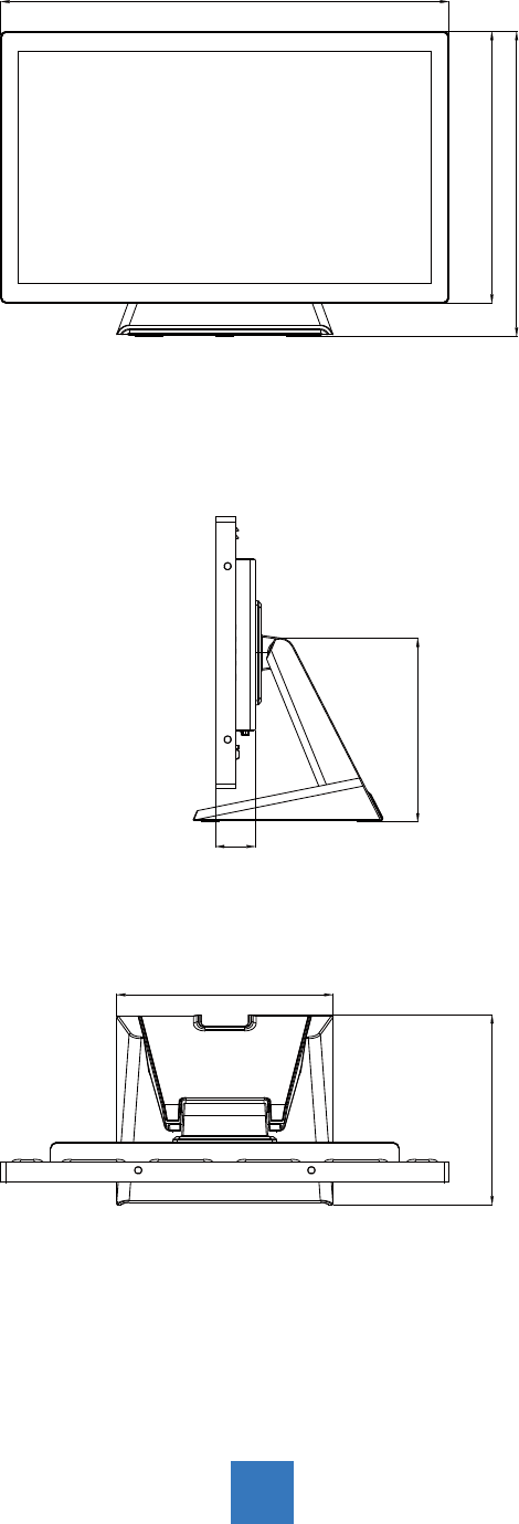
Product Dimensions
► Side View
► Front View
► Top View
351.7mm
212.0mm
46.0mm
219.0mm
517.4mm
313.3mm
249.6mm
23

Compatibility Modes
Mode Resolution H-Frequency(khz) V-Frequency(hz)
IBM VGA 720X400 31.47 70
IBM VGA 640X480 31.47 60
Apple MacII 640X480 35.00 66
VESA VGA 640X480 37.86 72
VESA VGA 640X480 37.50 75
VESA SVGA 800X600 35.16 56
VESA SVGA 800X600 37.88 60
VESA SVGA 800X600 48.08 72
VESA SVGA 800X600 46.88 75
Apple Mac 832X624 49.72 75
VESA XGA 1024X768 48.36 60
VESA XGA 1024X768 56.48 70
VESA XGA 1024X768 60.02 75
VESA SXGA 1280X1024 64.00 60
VESA SXGA 1280X1024 80.00 75
VESA SXGA 1152X864 67.50 75
VESA SXGA 1280X960 60.00 60
WXGA+ 1440X900 56.00 60
WXGA+ 1440X900 70.60 75
WSXGA+ 1680X1050 65.20 60
WSXGA+ 1680X1050 (VGA only) 82.30 75
VESA WXGA 1280X768 47.776 60
WSXGA+ 1920X1080 67.50 60
24

Touch Screen Driver Installation
The AMM215WTTP is available with USB connections. The touch driver is located on the
enclosed CD-ROM for these operating systems: VISTA, XP, 2000, CE, XP Embedded,
Linux, Apple® Mac OS.
Please Note:
1. The AMM215WTTP is Microsoft® Windows® HID (Human Interface Device) compatible
if you use the USB touch screen interface. No additional software driver is required for
general operation of the touch screen.
2. For AMM215WTTP, the system requires 15 seconds for Windows 7 to install/uninstall the
touch drivers while turning power on/off or plugging/unplugging USB cable.
AMM215WTTP Driver Install Instructions:
If you are using a PC running VISTA, XP, 2000, follow the instructions
below:
1. Power on the PC.
2. Be sure the USB cable is connected from the PC to the LCD display.
3. Open the CD-ROM.
4. Follow the step-by-step instructions as shown on the pop-up windows.
If you are using a PC running Windows® XP Embedded, follow the
instructions below:
Express:
1. Power on the computer.
2. Make sure that the USB cable is connected to the computer.
3. Be sure that your EWF is disabled. If your EWF is enabled, please disable the EWF
by using the EWF Manager command.
4. Once the EWF is disabled click on the XP driver on the CD-ROM and follow the
step-by-step instructions as shown on the pop-up windows.
Custom:
1. Power on the computer.
2. Make sure that the USB cable is connected to the computer.
3. Follow the step-by-step instructions found in the folder le on the CD-ROM.
25

If you are using a PC running Windows® CE, follow the instructions
below:
1. Power on the computer.
2. Make sure that the USB cable is connected to the computer.
3. Using Platform Builder, build an image le by following the step-by-step instructions
found in the folder le on the CD-ROM.
If you are using a PC running Linux or Apple® Mac OS, follow the
instructions below:
1. Power on the computer.
2. Make sure that the USB cable is connected to the computer.
3. Follow the step-by-step instructions found in the folder le on the CD-ROM.
26

Description of Warranty
ADVAN warrants to the rst Buyer (Buyer) that the product purchased when shipped in its
original container will conform to ADVAN specications, and to any ADVAN approved
specications furnished to ADVAN by the Buyer, and will be free of defects in materials and
workmanship. ADVAN warrants that the product purchased is manufactured from new com-
ponents which meet ADVAN’s standards, quality and specications.
Subject to the conditions and limitations set forth below, ADVAN will, at its option, either
repair any component of its products that prove defective by reason of improper
workmanship or materials or ADVAN has the exclusive right to replace with refurbished units
or with an equivalent product. ADVAN warrants that the components used for repair,
refurbished units or equivalent product will meet ADVAN standards, quality and
specications.
Commencement and Duration of Warranty
The product purchased will be warranted for a period of eighteen (18) months (excluding the
LCD panel, touch screen, and the protection lter) from the date of shipment.
LCD panels and touch screens are warranted for a period of twelve (12) months from the
date of shipment.
Protection lters are not warranted as damage to the protection lter is considered to be
normal wear and tear and can be replaced at the Buyer’s cost.
Components used for repair, refurbished units or equivalent product will be warranted for a
period of twelve (12) months from the date of repair.
Limitation of Warranty
This limited warranty does not cover any damage to this product or other non-ADVAN
products that results from any of the following: improper installation or operation; accident;
abuse; misuse; natural disaster; war; insufcient or excessive electrical supply; abnormal
mechanical or environmental conditions; any unauthorized disassembly, repair or
modication; normal wear and tear; tampering by anyone other than an ADVAN engineer or
an ADVAN Authorized Service Center (ASC); the use of supplies, consumable items and
conditions beyond the control of ADVAN, such as common carrier provided equipment and/
or facilities; operation of ADVAN product in excess of the specications. This limited warranty
also does not apply to any product that has not been handled or packaged correctly, that has
been sold as second-hand or has been resold contrary to the US export regulations,
on which the original identication information (i.e. serial number, rating and/or
warranty label) has been altered, obliterated or removed.
27

Return Material Authorization (RMA) Procedure
All claims must be submitted through the ADVAN website, whether in warranty or out, rst
Buyer, distributor or OEM. End Users who have purchased through a distributor or OEM,
please contact the distributor or OEM.
http://www.advancorprma.com
Follow the instructions to receive an RMA number, shipping instructions and a shipping label
to be placed on the outside of the shipping container. A serial number and a detailed reason
for return are required.
In-transit damage is not covered by warranty. ADVAN will only pay for the return
shipment by surface transportation.
Returns without an RMA number will not be accepted.
For product support, please e-mail details of your inquiry including product model:
service@advancorp.com
In Warranty
ADVAN or its ASC will repair or replace if defective in material or workmanship without cost,
for a period of eighteen (18) months, (LCD panels and touch screens for a period of twelve (12)
months) after the date of shipment.
Buyer must notify ADVAN or its ASC of the defect before expiration of the warranty period,
and request a RMA number. If the conguration has been modied in any manner, the
product must be returned to its original conguration before any warranty service will be
performed by ADVAN or its ASC. No goods are to be returned to ADVAN or its ASC without
prior authorization. Buyer will be responsible for packaging (preferably original container)
and shipping the defective goods to ADVAN or its ASC, shipping charges prepaid.
ADVAN or its ASC will return the in warranty product, at no cost to the buyer.
Out-of-Warranty
ADVAN or its ASC will repair or replace if defective in material or workmanship with
fee, any product which the warranty period has expired (out-of-warranty).
Buyer must notify ADVAN or its ASC of the defect and request a RMA number. If the
conguration has been modied in any manner, the product must be returned to its original
conguration before any service will be performed by ADVAN or its ASC.
No goods are to be returned to ADVAN or its ASC without prior authorization. Buyer will be
responsible for packaging (preferably original container) and shipping the defective goods to
ADVAN or its ASC, shipping charges prepaid.
ADVAN or its ASC will return the out-of-warranty product, at cost to the buyer.
28

Product End of Life (EOL)
In the event of a RMA of an EOL product(s), ADVAN will hold or store major components of
its products for a period of ve (5) years, after the EOL of its products. ADVAN shall continue
to perform the service of its products as long as ADVAN holds or stores said components of
the products, with reasonable charge.
The forgoing Warranty and Out-of-Warranty terms apply.
29

ADVAN Korea
#605, Kolon Science Valley 2-cha, 55, Digital-ro, 34-gil, Guro-gu, Seoul, 152-728
Korea
Tel : +82 2 783 5197
Fax : +82 2 868 0880
Web Page : http://www.advancorp.com
ADVAN INT’L CORP
47817 Fremont Blvd. Fremont, CA 94538, USA
Tel : 1 510 490 1005
Fax : 1 510 490 1151
Web Page : http://www.advancorp.com